Loading ...
Loading ...
Loading ...
7
L N
3. The wire which is coloured brown must be connected to the terminal marked “L”
(Live) or “A” (Active) or coloured Red.
■ A suitable isolating switch providing full disconnection from the mains power supply
(under overvoltage category III conditions) shall be incorporated in the permanent
wiring, mounted and positioned to comply with the local wiring rules and regulations.
The isolating switch must be of an approved type and provide a 3 mm air gap contact
separation in all poles (or in all active [phase] conductors if the local wiring rules allow
for this variation of the requirements).
■ The power supply cable must not touch the hot parts and must be positioned so that it
does not exceed 50°C above ambient.
■ Once the appliance has been installed, the switch or socket must always be accessible.
■ If the supply cord is damaged it must be replaced by the manufacturer or it’s Service
Agent or a similarly qualied person in order to avoid a hazard.
N.B. The connection of the appliance to earth is mandatory.
If the installation requires alterations to the domestic electrical system call a qualied
electrician.
He should also check that the socket cable section is suitable for the power drawn by the
appliance.
Replacing the power cord must be done by a qualied electrician in accordance
with the instructions supplied by the manufacturer and in compliance with
established electrical regulations.
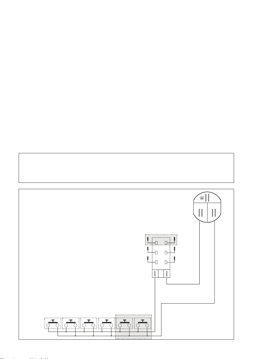
ELECTRIC DIAGRAM KEY
A Ignition coil
PA Ignition switches group (4÷6 depending on model)
CA Spark electrodes (4÷6 depending on model)
M Terminal block
DEGHBG70 model only:
If fitted with a 6-spark ignition coil,
the 6
th
outlet, not used, is earthed
by a ground strap in contact with
the basepan.
M
A
PA
CA
Figure 1
Loading ...
Loading ...
Loading ...