Loading ...
Loading ...
Loading ...
13
English
Before Operation
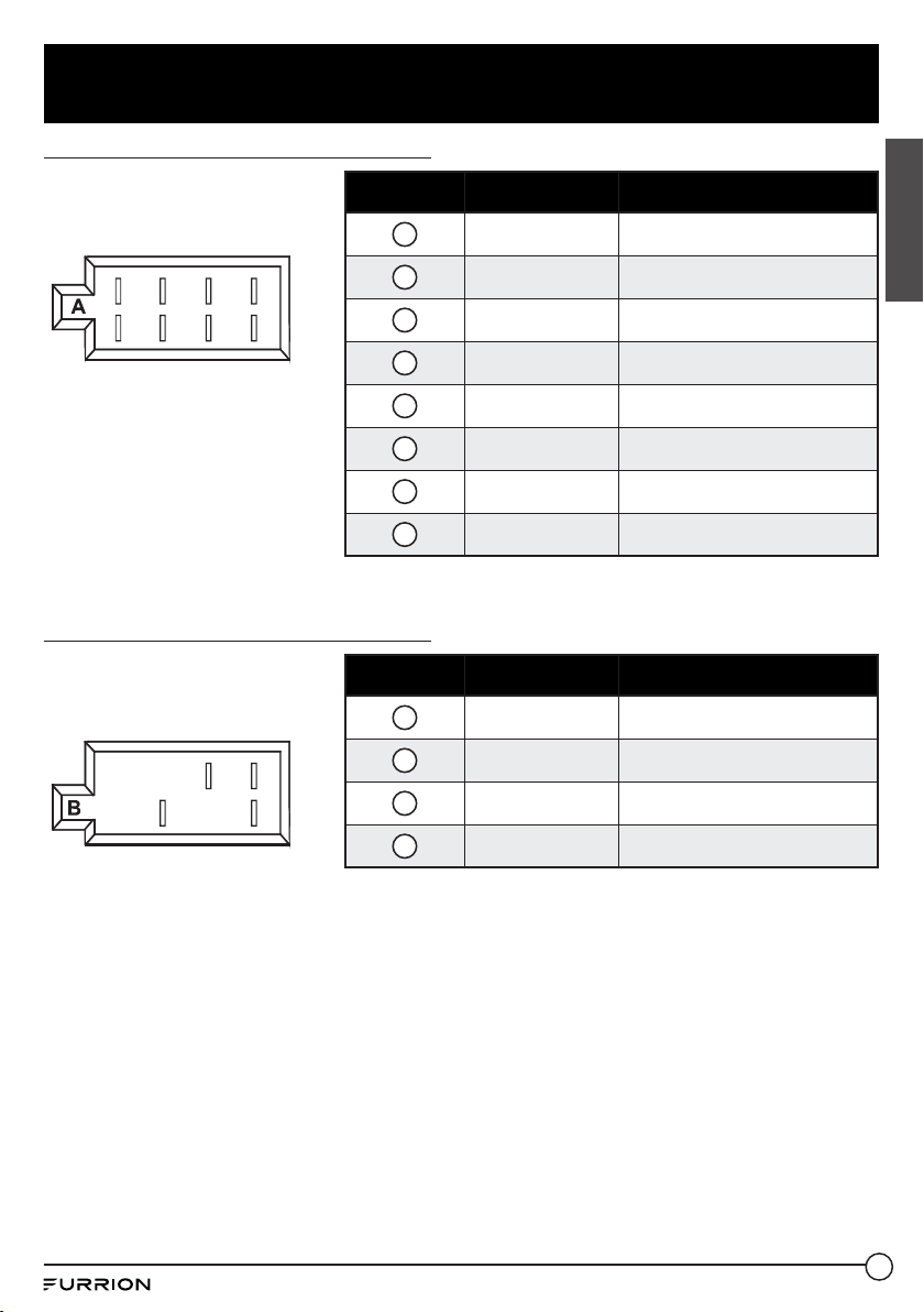
Wiring Connecting Socket A View
Pin No. Color Function
1
Purple Right (B) Speaker (+)
2
Purple/Black Right (B) Speaker (-)
3
Grey Right (A) Speaker (+)
4
Grey/Black Right (A) Speaker (-)
5
White Left (A) Speaker (+)
6
White/Black Left (A) Speaker (-)
7
Green Left (B) Speaker (+)
8
Green/Black Left (B) Speaker (-)
1 3 5 7
4 6 8
2
Wiring Connecting Socket B View
Pin No. Color Function
1
Yellow +12V DC Memory B+
2
Blue Auto Antenna
3
Red +12V DC Ignition Switch
4
Black Power Ground (-12 DC)
1
2 3
4
Loading ...
Loading ...
Loading ...