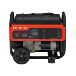
User Manual Generator
Features and Controls
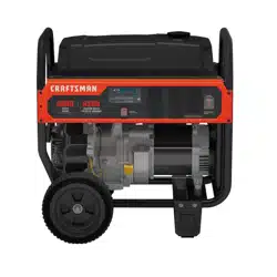
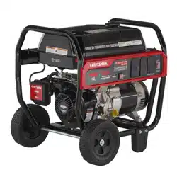
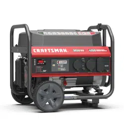
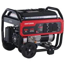
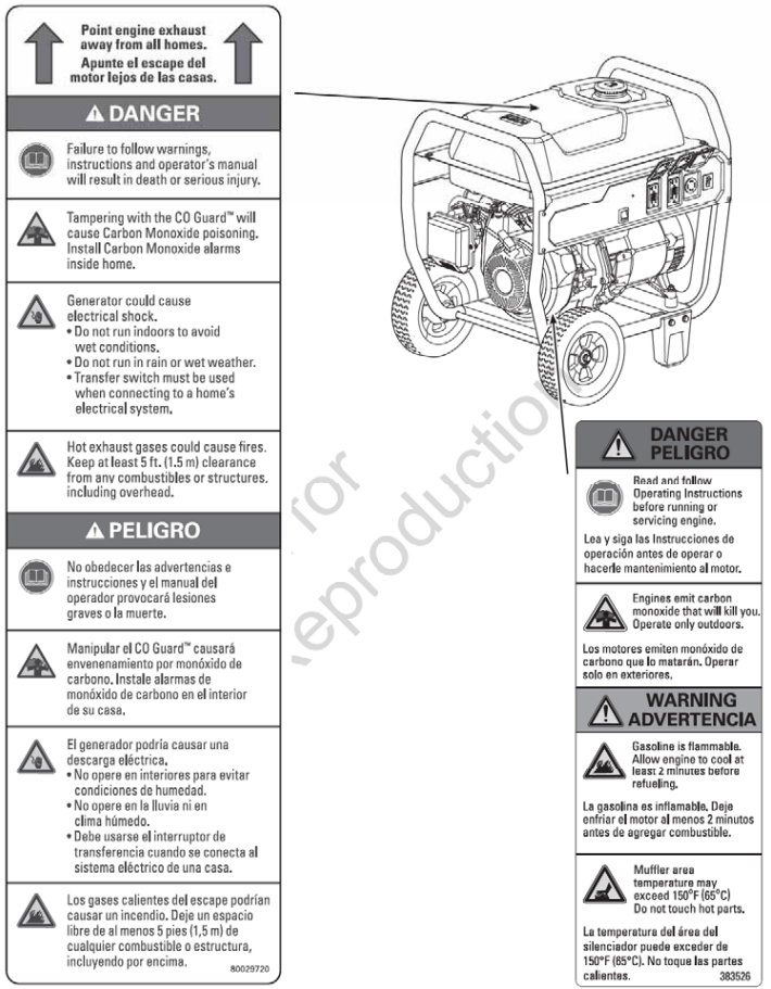
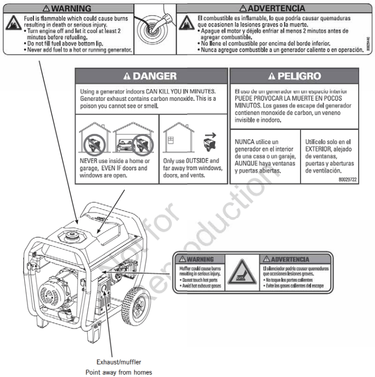
Compare the illustrations with your generator to familiarize yourself with the locations of various controls and product warnings.
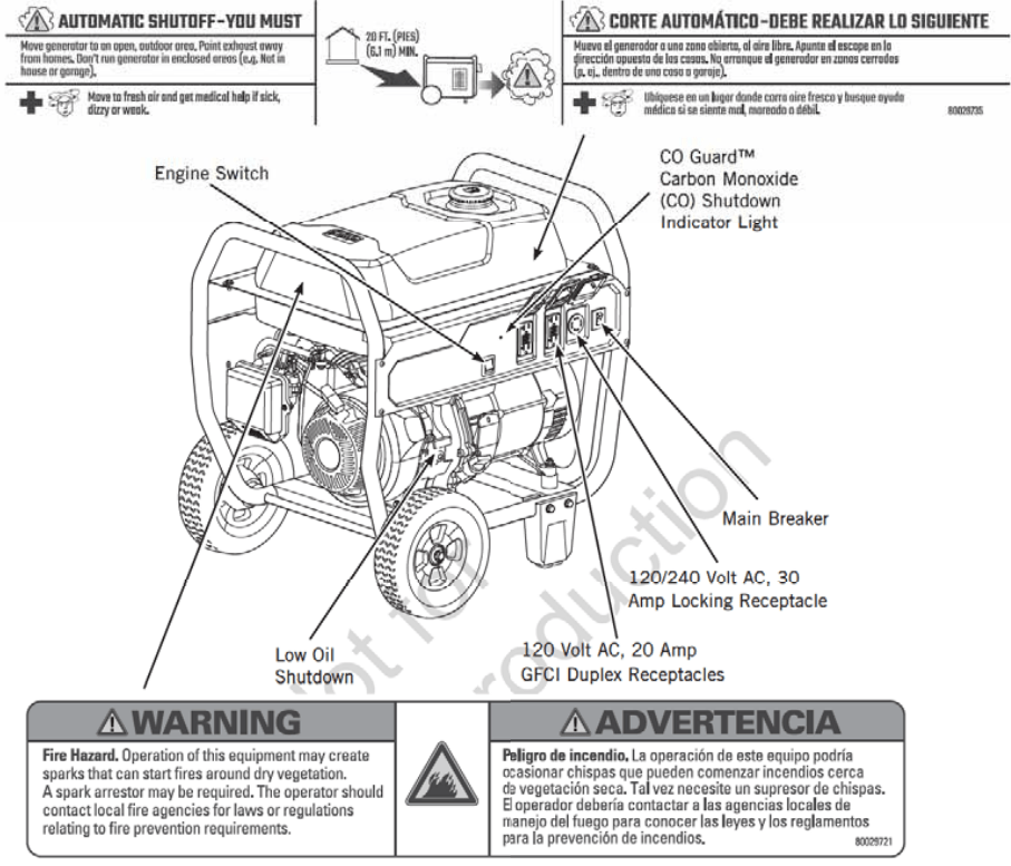
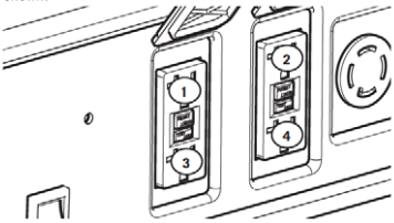
120 Volt AC, 20 Amp, GFCI Duplex Receptacles - Used to supply 120 Volt AC, single phase, 60 Hz power for electrical lighting, appliance, tool, and motor loads.
120/240 Volt AC, 30 Amp Locking Receptacle - Used to supply 120/240 Volt AC, single phase, 60 Hz power for electrical lighting, appliance, tool, and motor loads.
CO GuardTM Carbon Monoxide (CO) Shutdown Indicator Light - Indicates the engine shutdown due to carbon monoxide accumulation around the generator or a CO Guard system fault occurred.
Low Oil Shutdown - This unit is equipped with a low-oil protection device. Oil must be at the proper level for an engine to run. If the engine oil drops below a preset level, an oil switch will stop the engine. Check the oil level with the dipstick.
Main Breaker - Protects generator against electrical overload. If the breaker trips, it cuts power to all receptacles.
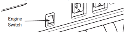
Engine Switch - Set this switch to ON (I) before starting the engine. Set the switch to OFF (0) to shut off the engine.
Operation
Step 1: Safe Location
Before starting the portable generator there are two equally essential safety concerns regarding carbon monoxide poisoning and fire that must be addressed.
Operation Location to Reduce the Risk of Carbon Monoxide Poisoning
The engine exhaust all fossil fuel-burning equipment. such as a portable generator. contains carbon monoxide. a poisonous gas that will kill you in minutes. You cannot smell it. see it. or taste it. Even if you do not smell exhaust fumes. you could still be exposed to carbon monoxide gas.
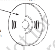
In many jurisdictions, it is required to have a carbon monoxide alarm in operating condition in your home. A carbon monoxide alarm is an electronic device that detects hazardous levels of carbon monoxide. When there is a buildup of carbon monoxide. the alarm will alert the occupants by flashing a visual indicator light and alarm. Smoke alarms cannot detect carbon monoxide gas.
Carbon Monoxide Alarm(s)
Install a carbon monoxide alarm inside your home. Without working carbon monoxide alarms. you will not realize you are getting sick and dying from carbon monoxide poisoning.
DANGER! Engine exhaust contains carbon monoxide, a poisonous gas that will kill you in minutes. You cannot smelt it. see it. or taste it. Even if you do not smell exhaust fumes. you could still be exposed to carbon monoxide gas.
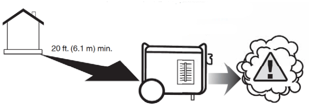
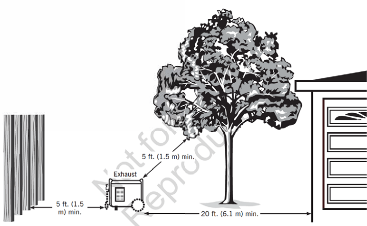
- Operate portable generator only outdoors. at least 20 ft. (6.1 m) from occupied spaces with exhaust pointed away to reduce the risk of carbon monoxide accumulation.
- Install battery-operated carbon monoxide alarms or plug-in carbon monoxide alarms with battery backup according to the manufacturer's instructions. Smoke alarms cannot detect carbon monoxide gas.
- Do not run a portable generator inside homes. garages. basements. crawlspaces. sheds. or other partially: enclosed spaces even if using fans or opening doors and windows for ventilation. Carbon monoxide can quickly build up in these spaces and can linger for hours. even after this product has shut off.
If you start to feel sick. dizzy. weak. or your home's carbon monoxide alarm sounds while using this product. get to fresh air right away. Call emergency services. You may have carbon monoxide poisoning.
Prevent carbon Monoxide (CO) Poisoning
- Use outdoors far away from any home.
- Point exhaust away from all homes and occupied spaces.
- Install CO alarms inside your home.
Operation Location to Reduce the Risk of Fire
WARNING! Exhaust heat/gases could ignite combustibles, and structures or damage the fuel tanks causing a fire. resulting in death or serious injury.
- A portable generator must be at least 5 ft. (1.5 m) from any structure. overhang. trees. shrubs. or vegetation over 12 in. (30.5 cm) in height.
- Do not place a portable generator under a deck or other type of structure that may confine airflow. Smoke alarm(s) must be installed and maintained indoors according to the manufacturer's instructions! recommendations.
- Carbon monoxide alarms cannot detect smoke.
- Do not place the portable generator in a manner other than shown.
Step 2: Oil and Fuel
The generator engine is shipped from the factory filled with 1030 oil. This allows for generator operation in a wide range of temperature and climate conditions. For checking to add or change oil see Maintenance.
Fuel must meet these requirements:
- Clean. fresh. unleaded fuel with a minimum of 87 octanes.
- Gasoline with an ethanol content of up to 10% is acceptable.

NOTICE Do not mix oil in fuel or modify the engine to run on alternate fuels. Use of unapproved fuels could damage the engine and will not be covered under warranty.
See High Altitude for 5. 00 ft. and above.
WARNING! Fuel and its vapors are extremely flammable which could cause burns or fire resulting in death or serious injury.
- Do not refuel! during operation.
- Do not smoke during refueling.
- Turn the engine off and let it cool for at least 2 minutes before removing the fuel cap.
- Fill the fuel tank outdoors. Keep fuel away from sparks. open flames. pilot lights. heat. and other ignition sources. Check fuel lines. tank. cap and fittings frequently for cracks or leaks. Replace if necessary.
- Slowly remove the fuel cap to relieve pressure in the tank.
- Slowly add unleaded fuel to the fuel tank. Be careful not to fill above the bottom lip. This allows adequate space for fuel expansion.
- Install the fuel cap and let any spilled fuel evaporate before starting the engine.
High Altitude
At altitudes over 5. 00 ft. (1524 m). a minimum of 85 octane fuel is acceptable. To remain emissions compliant. high altitude adjustment is required. Operation without this adjustment will cause decreased performance. increased fuel consumption. and increased emissions.
See an authorized Briggs & Stratton dealer for high altitude adjustment information. Operation of the engine at altitudes below 2. 00 ft. (762 m) with the high-altitude kilt is not recommended.
Transporting
When transporting equipment with a vehicle or trailer, turn the fuel shutoff valve to the off (0) position. Do not tip the engine or equipment at an angle that causes fuel to spill.
Step 3: Generator Start-Up
Disconnect all electrical loads from the generator. Use the following start instructions:
- Make sure the unit is outdoors on a level surface. NOTICE: Failure to operate the unit on a level surface may cause the unit to shut down.
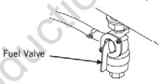
- Turn the fuel valve to the on (I) position.
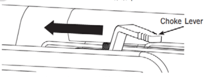
- Push the choke lever to the choke (|\|) position.
- Set the engine switch to the on (I) position.
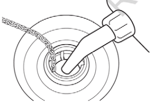
- Grasp the recoil handle and pull slowly until slight resistance is felt. Then pull rapidly to start the engine.
- Slowly move the choke lever to the run (I) position. If the engine falters. move the choke lever to the half-choke position until the engine runs smoothly. and then run the (I) position.
NOTICE If the engine starts but fails to run. see Low Oil Shutdown in Features and Controls.
Step 4: Connecting Electrical Loads
Using Extension Cords
Use only grounded extension cords marked for outdoor use and rated for your loads. Follow cord safety instructions.
WARNING! Damaged or overloaded extension ta cords could overheat. arc. and burn resulting in death or serious injury.
NOTICE For best results when plugging into the 120 Volt GFCI receptacles. plug items to be powered in sequence as shown.
NOTICE For generator output required see Generator Capacity. Connect electrical loads in the off position then turn them on for operation.
120 Volt AC. 20 Amp. GFCI Duplex Receptacles
Use each receptacle to operate 120 Volt AC, single-phase, 60 Hz electrical loads requiring up to 2. 00 Watts (2.4 kW) at 20 Amps of current.
Ground Fault Protection
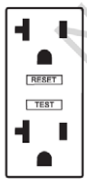
The duplex receptacles are equipped with Ground Fault Circuit Interrupter (GFC!) protection. The GFCI protects against electrical shock that may be caused if your body becomes a path in which electricity travels to reach the ground.
When protected by a GFCI. one may still feel a shock. but the GFCI is intended to cut current off quickly enough so that a person in normal health should not suffer any serious electrical injury
WARNING Generator voltage could cause electrical shock or burn to result in death or serious injury. Contact with the hot and neutral conductor at the same time could cause electrical shock or burn. even if the circuit is GFCI protected.
Testing the GFC!
With the engine running. test your GFC! outlet prior to. each use. as follows:
- Push the “Test” button. The “Reset” button should pop out. which should/allow no power to reach the outlet.
- Press the “Reset” button firmly until it is fully in place and locks in that position. If the GFCI outlet does not reset properly. do not use the outlet. Call or take your generator to a local service center.
- If the GFCI trips by itself at any time. reset and test the outlet.
120/240 Volt AC. 30 Amp. Locking Receptacle
Use a NEMA L14-30 plug with this receptacle. Connect a 4-wire cord set rated for 250 Volt AC loads at 30 Amps. The generator's locking receptacle is not protected by a GFCI.
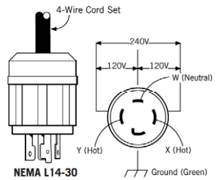
This receptacle powers 120/240 Volt AC. 60 Hz. single phase loads requiring up to 5. 00 Watts of power (5.0 kW) at 20.8 Amps for 240 Volts or two independent 120 Volt loads at 20.8 Amps each.
Generator Capacity
To make sure your generator can supply enough running. watts and starting watts for the items you will power at the same time. follow these three simple steps:
- Select the items you will power at the same time. See the following list for typical wattages.
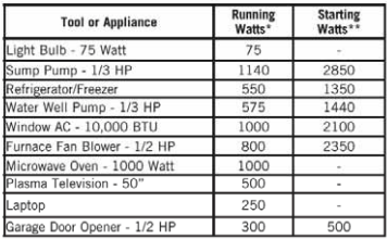 * Typical wattages listed are approximate only. Check the tool or appliance for actual wattage.
** The momentary electrical current the generator can provide to start electric motors. per Briggs & Stratton standard 628K. It does not represent the power required to continuously run electrical loads. It is the maximum current that can momentarily be supplied when starting a motor. multiplied by the generator's rated voltage.
- Total the running watts. This is the amount of power your generator must produce to keep: your items running. See the following example:
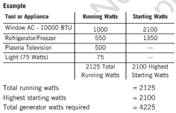
- Estimate the starting watts you will need. Because not all motors start at the same time. total starting wattage can be estimated by adding only the item with the highest additional starting watts requirements to the total running watts from step 2.
Power Management
To manage generator power. sequentially add loads as follows:
- With nothing connected to the generator. start the engine outdoors.
- Plug in and turn on the first load. preferably the largest load you have.
- Permit the generator output to stabilize (the engine runs smoothly and the attached device operates properly).
- Plug in and turn on the next load.
- Again. permit the generator to stabilize.
- Repeat steps 4 and 5 for each additional load.
Never add more loads than the generator capacity. Take special care to consider starting watts in generator capacity.
CO Guard
Carbon Monoxide (CO) Shutdown System
CO Guard automatically shuts down the engine when harmful levels of carbon monoxide accumulate around the generator or a CO Guard fault occurs. After shutdown. the CO Guard indicator light will blink for at least five minutes per the chart below.
CO Guard DOES NOT replace carbon monoxide alarms.
Install battery-powered carbon monoxide alarm(s) in your home. Don’t run the generator in enclosed areas.
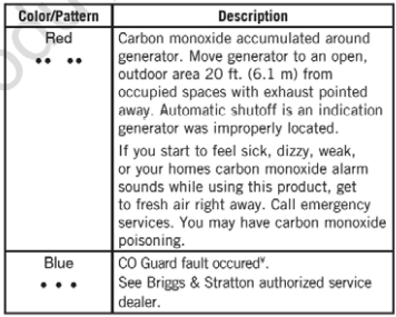
* Blue light will link for five seconds at the startup of the generator to show the CO Guard functioning properly.
Step 5: Generator Shutdown
- Turn off and unplug all electrical loads from the generator panel receptacles. Never stop the engine with electrical devices plugged in and turned on.
- Let the engine run at no-load for one minute to stabilize the internal temperatures of the engine and generator.
- Push the engine switch to the off (0) position.
- Move the fuel valve to the off (0) position.
Maintenance
Maintenance Schedule
Follow the hourly or calendar intervals. whichever occurs first. More frequent service is required when operating in adverse conditions noted below.
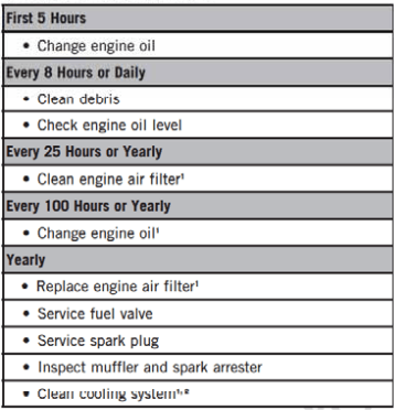
1 Service more often under dirty or dusty conditions.
2 See any authorized dealer for service.
General Recommendations
Regular maintenance will improve the performance and. extend the life of the generator. Servant authorized dealer for service.
The generator's warranty does not cover items that have been subjected to operator abuse or negligence To receive full value from the warranty. the operator must maintain the generator as instructed in this manual.
All service and adjustments should be made at least once each season. A new spark plug and clean air filter assure proper fuel-air mixture and help your engine run better and last longer. Follow the requirements in the Maintenance Schedule.
Emissions Control
Maintenance. replacement. or repair of the emissions control devices and systems may be performed by any non-road engine repair establishment or individual. However. to obtain a "no charge” emissions control service. the work must be performed by a factory-authorized dealer. See Emissions Warranty.
Cleaning
Daily or before use. look around and underneath the generator for signs of oil or fuel leaks. Clean any accumulated debris. Keep the area around the muffler free from any debris.
- Use a soft bristle brush to loosen caked-on dirt or
- Use 8 damp cloths to wipe exterior surfaces clean.
NOTICE Improper treatment of the generator could damage it and shorten its life. Do not expose the generator to excessive moisture. dust. dirt. or corrosive vapors. Do not insert any objects through cooling slots.
Fuel Valve Maintenance
The fuel valve is equipped with a fuel sediment cup. screen. and o-rings that need to be cleaned.
- Move the fuel valve to the off (0) position.
- Remove the sediment cup from the fuel valve. Remove the O-ring and screen from the fuel valve.
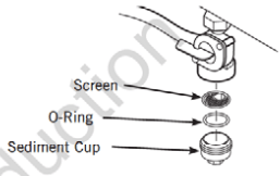
- Wash the sediment cup. o-ring. and screen in a nonflammable solvent. Dry them thoroughly.
- Place screen and o-ring into fuel valve. Install the sediment cup and tighten it securely.
- Move the fuel valve to on (1) position. and check for leaks. Replace the fuel valve if there is any leakage.
Engine Maintenance
Oil Recommendations
We recommend the use of Briggs & Stratton Warranty Certified oils for best performance. Other high-quality detergent oils are acceptable if classified for service SF or higher. Do not use special additives. See Common Service Parts.
Outdoor temperatures determine the proper oil viscosity for the engine. Use the chart to select the best viscosity for the outdoor temperature range expected.
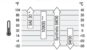
* Below 4°C (40°F) the use of SAE 30 will result in hard starting.
** Above 27°C (80°F) the use of 10930 may cause increased oil consumption. Check oil level more frequently
Checking/Adding Engine Oil
Oil level should be checked prior to each use or at least every 8 hours of operation. Keep oil level maintained.
- Make sure the generator is on a level surface.
- Clean the area around the oil fill. remove dipsitck and wipe with a clean cloth. Replace dipstick. Remove and check the oil level. NOTICE Do not screw in the dipstick when checking the oil level.
- Verify oil is at the full mark on the dipstick. Replace and tighten the dipstick.

- If needed. slowly pour oil into oil full mark on the dipstick. Do not overfill
NOTICE Overfilling with oil could cause the engine to not start. or hard starting.
- Do not overfill.
- If over the full mark on the dipstick. drain oil to reduce the oil level to full mark on the dipstick.
5. Replace and tighten the dipstick.
NOTICE Do not attempt to crank or start the engine before it has been properly serviced with recommended oil. This could result in engine failure.
CAUTION Avoid prolonged or repeated skin contact with used motor oil. Used motor oil has been shown to cause skin cancer in certain laboratory animals. Thoroughly wash exposed areas with soap and water.
KEEP OUT OF REACH OF CHILDREN. DON'T POLLUTE. CONSERVE RESOURCES. RETURN USED OIL TO COLLECTION CENTERS.
Changing Engine Oil
If you are using your generator under extremely dirty or dusty conditions. or in extremely hot weather. change the more often.
Change the oil while the engine is still warm from running. as follows:
- Make sure the unit is on a level surface.
- Remove the oil drain plug and drain the oil completely into a suitable container.
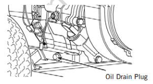
- Reinstall the oil drain plug and tighten it securely. Remove dipstick.
- Slowly pour recommended oil (about 36 o7. (1.0 1)) into the oil fill opening. Pause to permit oil to settle. Fill to Full mark on the dipstick.
- Wipe the dipstick clean each time the oil level is checked. Do not overfill.
- Reinstall dipstick. Tighten the cap securely.
- Wipe up any spilled oil.
Service Air Cleaner
Your engine will not run properly and may be damaged if you run it with a dirty air cleaner. Clean or replace more often if operating under dusty or dirty conditions.
- Loosen the screws and remove the air cleaner cover.
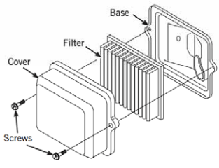
- Carefully remove the cartridge from the base.
- Install clean (or new) air cleaner assembly inside the cover. Dispose of the old filter properly. NOTICE If the filter is excessively dirty. replace with a new filter. See Common Service Parts.
- Assemble the air cleaner cover onto the base and tighten the screws.
Service Spark Plug
Changing the spark plug will help your engine to start easier and run better.
- Clean the area around the spark plug.
- Remove and inspect the spark plug.
- Replace the spark plug if the electrodes are pitted. buried or porcelain is cracked. Use the recommended. replacement spark plug. See Common Service Parts.
- Check the electrode gap with the wire feeler gauge and reset the spark plug gap to recommended gap.
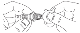
- Install the spark plug and tighten it firmly.
Inspect Muffler and Spark Arrester
The engine exhaust muffler has a spark arrester screen. Inspect the muffler for cracks. corrosion. or other damage. Inspect the spark arrester screen for damage or carbon blockage. Clean if carbon blockage is found using a brush and commercial solvent or replace it damaged.
WARNING! Contact with the muffler area could cause burns resulting in serious injury.
- Allow equipment to cool before servicing
- It is 2 violation of the California Public Resource Code. Section 4442. to use or operate the engine on any forest covered. brush-covered. or grass-covered land unless the exhaust system is equipped with a spark arrester. as defined in Section 4442. maintained in effective working order. Other states or federal jurisdictions may have similar laws. reference Federal Regulation 36 CFR Part 261.52.
Replace spark arrester as follows:
- Remove four screws that: connect the heat shield to the muffler.
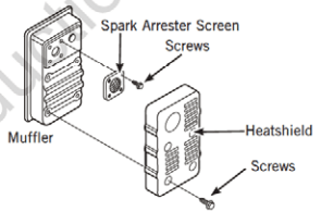
- Remove four screws that attach the spark arrester screen.
- Obtain a replacement screen.
- Reattach the screen and muffler guard.
Common Service Parts
Air Cleaner........................ 491588 or 5043
Spark Plug..................................... 795615
Engine Oil Bottle.............................100028
Synthetic Oil Bottle..........................100074
Fuel Stabilizer................ 100120 or 100117
Contact an authorized service dealer or BRIGGSandSTRATTON.COM for a full list of parts and diagrams.
Troubleshooting/Specifications
The engine is running, but no AC output is available.
- One of the circuit breakers is Open.
- Reset the circuit breaker.
- Poor connection or defective cord set.
- A connected device is bad.
- Connect another device that is in good condition.
- GFCI is tripped.
The engine runs well at no-load but “bogs down” when loads are connected.
- The generator is overloaded.
The engine will not start; starts and runs rough or shuts down when running.
- Engine switch set to off (0) position.
- Set the switch to the on (I) position.
- The fuel valve is in the off (0) position.
- Turn the fuel valve to the on (I) position.
- Low oil level.
- Fill the crankcase to the proper level or place the generator on a level surface.
- Dirty air cleaner.
- Clean or replace the air cleaner.
- Out of fuel.
- The spark plug wire is not connected to the spark plug.
- Connect a wire to the spark plug.
- Flooded with fuel.
- Wait 5 minutes and re-crank the engine.
The engine shut down and CO Guard LED blinks red
- The generator is improperly located.
- Move the generator to an open. outdoor area. See CO Guard Carbon Monoxide (CO) Shutdown System.
For all other issues. see a Briggs & Stratton authorized dealer.
Specifications
Rated Wattage*..................................................5.000 Watts
Starting Wattage**..............................................8.500 Watts
AC Current at 240 Volts........................................20.8 Amps
AC Current at 120 Volt....................................... 141.6 Amps
Frequency.................................................60 He at 3600 rpm
Phase................................................................Single Phase
Displacement....................................... 18.68 cu. in. (306 cc)
Spark Plug Gap...................................... 0.030 in. (0.76 mm)
Fuel Capacity.............................8.5 US. Gallons (32.2 Liters)
Oil Capacity ........................................36 Ounces (1.0 Liters)
Power Ratings: The gross power rating for individual gasoline engine models is labeled in accordance with SAE(Society of Automotive Engineers) code J1940 Small Engine Power & Torque Rating Procedure, and is rated in accordance with SAE J1995. Torque values are derived at 2600 RPM for those engines with “rpm” called out on the label and 3060 RPM for all others; horsepower values are derived at 3600 RPM. Net power values are taken with exhaust and air cleaner installed whereas gross power values are collected without these attachments. Actual gross engine power will be higher than net engine power and is affected by. among other things. ambient operating conditions and engine-to-engine variability. Given the wide array of products on which engines are placed. the gasoline engine may not develop the rated gross power when used in a given piece of power equipment. This difference is due to a variety of factors including. but not limited to. the variety of engine components (air cleaner. exhaust. charging. cooling. carburetor. fuel pump. et.) application limitations. ambient operating conditions (temperature. humidity. altitude). and engine-to-engine variability. Due to manufacturing and capacity limitations. Briggs & Stratton may substitute an engine of higher-rated power for this engine.
* Generator per PGMA (Portable Generator Manufacturers’ Association) standard ANSUIPGMA G300-2018, Safety, and Performance of Portable Generators
** Per Briggs & Stratton 628K