Loading ...
Loading ...
Loading ...
INSTALLATION
Check the appliance is electrically safe and gas sound when you have nished.
36
Reducer plates
Reversible conduit box cover
Conduit box
M4 screw
M5 screws
Reducer plates
M4 screw
ArtNo.132-0002 - 3 phase 240/415Vac 50Hz
3-phase 400 V
AC
50 Hz
Connection in New Zealand
Type of cord in accordance with IEC 60227 with a minimum
rating of 90°C.
Cord size recommended for this application is 3 x 10 mm²,
three-core cable (Power cables may be sized to take into
account the coincidence factor AS/NZS 60335.2.6:2014).
Rating of the plug is 32 Amp, in accordance with AS/NZS
3112. Based on the arithmetic mean value when measured
under full load stabilized conditions, Clause 10 IEC 60335-1.
If this cooking range is to be connected to a new or upgrade
electrical installation, then it must be connected to the
supply by a supply cord tted with:
• An appropriately rated plug that is compatible with the
socket – outlet fitted to the final sub –circuit in the fixed
wiring that supplies this cooking range
OR
• An appropriately rated installation male connector that
is compatible with the installation female connector
fitted to the final sub circuit in the fixed wiring that
supplies this cooking range.
Note: The marking for the rated current of the fuse protecting
a socket should be placed on or near the socket outlet.
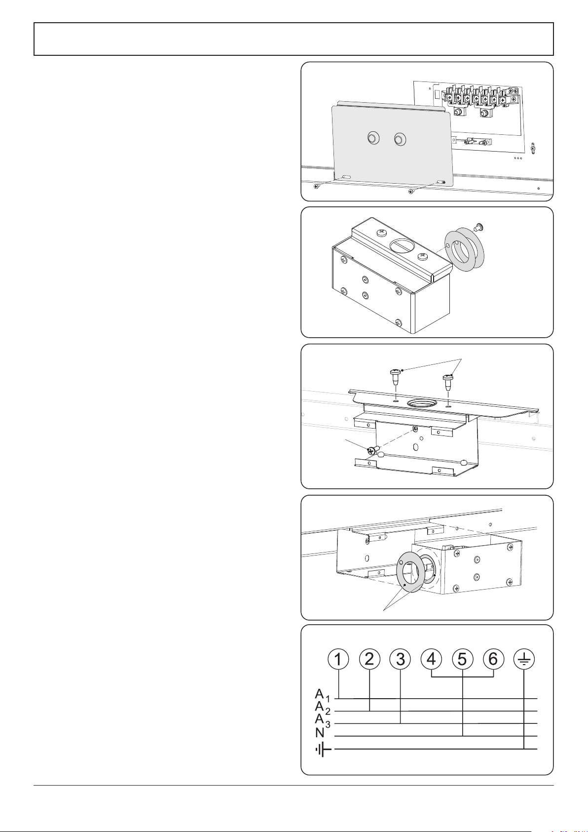
Fixed Wiring
n
Disconnect from the mains supply.
For connection to xed wiring, i.e. exible conduit, remove
the electrical terminal cover box on the back panel
(Fig. 10.14).
Remove the M4 screw securing the reducer plates to the
conduit box (Fig. 10.15).
Fit the conduit box to the cooker using the two M5 screw
ttings located at the top of the box. Remove the M4 screw
from the base, and x to the cooker, via the tting through
the back of the conduit box (Fig. 10.16).
The conduit box cover is reversible. Fit the reducer plate if
required (Fig. 10.17). Feed the cable through the conduit box
and secure in place with the cable clamp.
Connect the mains cable to the correct terminals for your
electrical supply type (Fig. 10.18). Check that the links are
correctly tted and that the terminal screws are tight.
Fit the cover to the conduit box.
Fig. 10.14
Fig. 10.15
Fig. 10.16
Fig. 10.17
Fig. 10.18
Loading ...
Loading ...
Loading ...