Loading ...
Loading ...
Loading ...
FRONT WHEEL TOE-IN ADJUSTMENT
Front wheel toe-in is required for proper steering operation,,
Toe-in was set at the factory and adjustment should not be
necessary,, if parts inthe front axle or steering mechanism
have been replaced or damaged, check toe-in and adjust
if necessary.,
TO CHECK TOE-IN (See Fig° 28) -
o Position front wheels straight ahead,,
o Measure distance between wheels at front and rear of
tires (dimensions "A" and "B").,
- Front dimension "A" should be 1/8" to 1/4" less than
rear dimension "B".,
TO ADJUST TOE-IN (See Figs. 28 and 29) -
. Loosen jam nuts at adjustment sleeves on tie rod_
: Adjusttieroduntitdimension"A"isl/8"tol/4"lessthan
dimension "B".,
° Tighten jam nuts securely.
WAS!
RETAINING
RING
AXLE
COVER
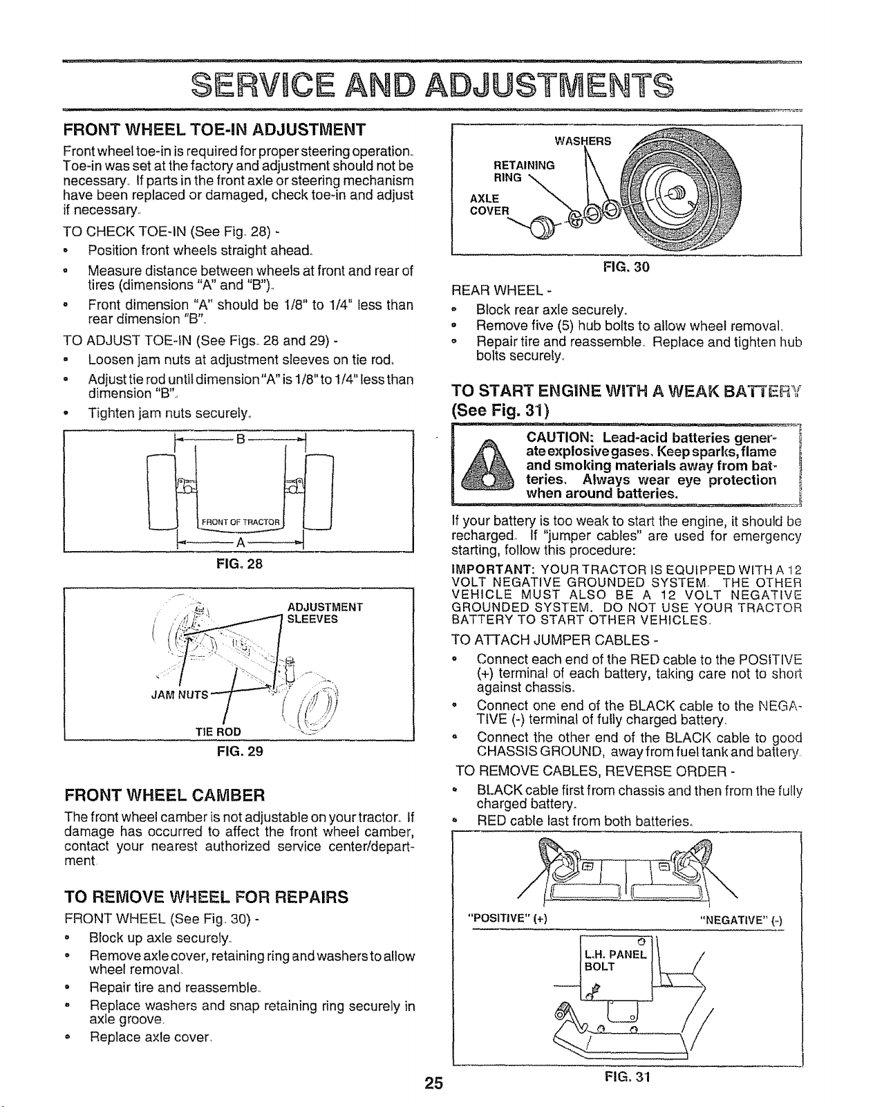
FIG. 30
REAR WHEEL -
° Block rear axle securely.
o Remove five (5) hub bolts to allow wheel removal,,
- Repair tire and reassemble, Replace and tighten hub
bolts securely_
TO START ENGINE WiTH A WEAK IBATTEFiY
(See Fig. 31)
__B
,,_A _
FIG. 28
, ADJUSTMENT
i SLEEVES
JAM
TIE ROD
FIG. 29
FRONT WHEEL CAMBER
The front wheel camber is not adjustable on your tractor,, If
damage has occurred to affect the front wheef camber,
contact your nearest authorized service centeddepart-
ment
TO REMOVE WHEEL FOR REPAIRS
FRONT WHEEL (See Fig., 30) -
o Block up axfe securely..
o Remove axle cover, retaining ring and washers to allow
wheel removal
• Repair tire and reassemble.,
° Replace washers and snap retaining ring securely in
axle groove.
. Replace axle cover,
If your battery is too weak to start the engine, it should be
recharged, if "jumper cables" are used for emergency
starting, follow this procedure:
IMPORTANT: YOUR TRACTOR IS EQUIPPED WITH A 12
VOLT NEGATIVE GROUNDED SYSTEM, THE OTHER
VEHICLE MUST ALSO BE A 12 VOLT NEGATIVE
GROUNDED SYSTEM. DO NOT USE YOUR TRACTOR
BATTERY TO START OTHER VEHICLES,,
TO ATTACH JUMPER CABLES -
o Connect each end of the RED cable to the POSITIVE
(+) terminal of each battery, taking care not to short
against chassis.
• Connect one end of the BLACK cable to the NEGA-
TIVE (-) terminal of fully charged battery,
• Connect the other end of the BLACK cable to good
CHASSIS GROUND, away from fuel tank and battery,
TO REMOVE CABLES, REVERSE ORDER -
° BLACK cable first from chassis and then from the fully
charged battery.
. RED cable last from both batteries°
"POSITIVE" (+)
"NEGATIVE" {-)
BOLT
r_
25 FIG, 31
Loading ...
Loading ...
Loading ...