
......, CI / I _
f_
®
MODEL NU 917.250560 OWNER'S MANUAL
° Assembly
o Operation
° Customer Responsibilities
o Service and Adjustments
o Repair Parts
CAUTION: Read and follow all safety rules and instructions before operating this equipment.
FOR CONSUMER ASSISTANCE HOT LINE, CALL THIS TOLL FREE NUMBER: 1-800-659-5917
_11111i ........... r,, ...............
SAFETY RULES
Safe Operation Practices for Ride-On Mowers
IMPORTANT: THIS CUTTING MACHINE IS CAPABLE OF AMPUTATING HANDS AND FEET AND THROWING OBJECTS..
FAILURE TO OBSERVE THE FOLLOWING SAFETY INSTRUCTIONS COULD RESULT IN SERIOUS INJURY OR DEATH.
I. GENERAL OPERATION
• Read, understand, and follow all instructions in the manual
and on the machine before starting.
• Only allow responsible adults, who are familiar with the
instructions, to operate the machine,
• Cleat the area of objects such as rocks, toys, wire, etc.,,
which could be picked up and thrown by the blade.
• Be sure the area isclear of other people before mowing Stop
machine if anyone enters the area°
• Never carry passengers._
• Do not mow in reverse unless absolutely necessary. Always
look down and behind before and while backing.
- Be aware of the mower discharge direction and do not point
it at anyone. Do not operate the mower without either the
entire grass catcher or the guard in place
• Slow down before turning,
° Never leave a running machine unattended. Always turn off
blades, set parking brake, stop engine, and remove keys
before dismounting.
° Turn off blades when not mowing,
° Stop engine before removing grass catcher or unclogging
chute.
° Mow only in daylight or good artificial light
• Do not operate the machine while under the influence of
alcohol or drugs.
° Watch for traffic when operating near or crossing roadways.
° Use extra care when loading or unloading the machine into
a trailer"or truck
Ii. SLOPE OPERATION
Slopes are a major factor related to loss-of-control and
tipover accidents, which can result in severe injury ordeatho
All slopes require extra caution. If you cannot back up the
slope or if you feel uneasy on it, do not mow it.
DO:
° Mow up and down slopes, not across.
° Remove obstacles such as rocks, tree limbs, etc..
• Watch for holes, ruts, or bumps. Uneven terrain could
overturn the machine. Tall grass can hide obstacles°
° Use slow speed. Choose a low gear so that you wilt not have
to stop or shift while on the slope_
° Follow the manufacturer's recommendations for wheel
weights or counterweights to improve stability.,
• Use extra care with grass catchers or other attachments
These can change the stability of the machine
° Keep al! movement on the slopes stowand gradual Do not
make sudden changes in speed or direction..
• Avoid starting ot stopping on a slope. If tires lose traction,
disengage the blades and proceed slowly straight down the
slope.
DO NOT:
• Do not turnon slopes unless necessary, and then, turn slowly
and gradually downhill, if possible,
° Do not mow near drop-offs, ditches, or embankments. The
mower could suddenly turn over ifa wheel is over the edge
of a cliff or ditch, or it an edge caves in.,
• Do not mow on wet grass. Reduced traction could cause
sliding.
• Do not try to stabilize the machine by putting your foot on the
ground.
° Do not use grass catcher on steep slopes,
2
!11. CHILDREN
Tragic accidents can occur if the operator is not alert to the
presence of children, Children are often attracted to the
machine and the mowing activity. Never assume that
children will remain where you last saw them.
= Keep children out of the mowing area and under the watchful
care of another responsible adult..
° Be alert and turn machine off if children enter the area
° Before and when backing, look behind and down for small
children.
° Never carry children. They may fall off and be seriously
injured or interfere with sate machine operation
- Never allow children to operate the machine.
• Use extra care when approaching blind corners, shrubs,
trees, or other"objects that may obscure vision.
IV. SERVICE
• Use extra care in handling gasoline and other fuels.. They are
flammable and vapors are explosive.
Use only an approved container,
Never remove gas cap or add fuel with the engine
running. Allow engine to cool before refueling.. Do not
smoke.
Never refuel the machine indoors.
Never store the machine or fuel container inside where
there is an open flame, such as a water heater'..
• Never run a machine inside a closed area.
° Keep nuts and bolts, especially blade attachment bolts, tight
and keep equipment in good condition
° Never tamper' with safety devices. Check their proper
operation regularly.
° Keep machine free of grass, leaves, or other debris build-up,
Clean oil or fuel spil_age.. Allow machine to cool before
storing.
° Stop and inspect the equipment if you strike an object
Repair, if necessary, before restarting.
• Never make adjustments or repairs with the engine running
• Grass catcher components are subject towear', damage, and
deterioration, which could expose moving parts or allow
objects to be thrown. Frequently check components and
replace with manufacturer's recommended parts, when nec-
essary_
• Mower blades are sharp and can cut. Wrap the blade(s) or
wear gloves, and use extra caution when servicing them
• Check brake operation frequently. Adiust and service as
required.
Look for this symbol to point out impor-
tant safety precautions. It means
CAUTIONH! BECOME ALERT]If YOUR
SAFETY IS INVOLVED.
,,, , , i, ,!!,iiiI , ,,,,,,.... !
CAUTION: Always disconnect spark plug
_ wire and place wire where it cannot contact
spark plug in order to prevent accidental
starting when setting up, transporting,
adjusting or making repairs.
_i _ _i ii " '
WARNING A
The engine exhaust from this product con-
tains chemicals known to the State of Califor-
nia to cause cancer, birth defects, or other
reproductive harm.

CONGRATULATIONS on your purchase of a Sears
Tractor It has been designed, engineered and manufac-
tured to give you the best possibfe dependability and
performance_
Should you experience any problem you cannot easily
remedy, please contact your nearest Sears Authorized
Service Center/Department Department. We have com-
petent, well-trained technicians and the proper tools to
service or repair this tractor°
Please read and retain this manual, The instructions wilt
enable you to assemble and maintain your tractor properly°
Always observe the "SAFETY RULES",
MODEL
NUMBER 917 250560
SERIAL
NUMBER
DATEOFPURCHASE
THE MODEL AND SERIAL NUMBERS WiLL BE FOUND
ON A PLATE UNDER THE SEAT°
YOU SHOULD RECORD BOTH SERIAL NUMBER AND
DATE OF PURCHASE AND KEEP IN A SAFE PLACE
FOR FUTURE REFERENCE.
MAINTENANCE AGREEMENT
A Sears Maintenance Agreement is available on this prod-
uct Contact your nearest Sears store for details
CUSTOMER RESPONSIBILITIES
= Read and observe the safety rules.
= Follow a regular schedule in maintaining, caring for and
using your tractor.
= Follow the instructions under "Customer Responsibili-
ties" and "Storage" sections of this owner's manual°
PRODUCT SPECIIFIICATmONS
HORSEPOWER: 22_5
GASOLINE CAPACITY 3..5 GALLONS
AND TYPE: UNLEADED REGULAR
OIL TYPE (APFSF/SG): SAE 10W30 (above 32°F)
SAE 5W-30 (below 32°F)
OIL CAPACITY: W/FILTER: 4..2 PINTS
W/O FILTER: 37 PINTS
SPARK PLUG: CHAMPION RC12YC
(GAP: 040")
VALVE CLEARANCE: NOT ADJUSTABLE
GROUND SPEED {MPH): FORWARD: 0 - 56
REVERSE: O- 2.5
TIRE PRESSURE: FRONT: 14 PSi
REAR: t0 PSi
CHARGING SYSTEM: 15 AMPS @ 3600 RPM
BLADE BOLT TORQUE: 30-35 F'T. LBS
WARNING: This tractor is equipped with an internal
combustion engine and should not be used on or near any
unimproved foresFcovered, brush-covered or grass-cov-
ered land unless the engine's exhaust system is equipped
with a spark arrester meeting applicable local or state laws
(if any)_ If a spark arrester is used, it should be maintained
in effective working order by the operator..
In the state of California the above is required by law
(Section 4442 of the California Public Resources Code)
Other states may have similar laws. Federal laws apply on
federal lands. A spark arrester for the muffler is available
through your nearest Sears Authorized Service Center/
Department (See REPAIR PARTS section of this manual).
Lit,tilTED TWO YEAR WARRANTY ON CRAFTSMAN RIDWNG EQURPMENT
For two (2) years from the date of purchase, if this Craftsman Riding Equipment is maintained, lubricated and tuned up according
to the instructions in the owner's manual, Sears will repair or replace, free of charge, any parts found to be defective in material
or workmanship..
This Warranty does not cover:
• Expendable items which become worn during normal use, such as blades, spark plugs, air cleaners, belts, etc.
° Tire replacement or repair caused by punctures from outside objects, such as nails, thorns, stumps, or glass..
o Repairs necessary because of operator abuse, negligence, improper storage or accident or the failure to maintain the
equipment according to the instructions contained in the owner's manual
o Riding equipment used for commercial or rental purposes°
UMITED 90 DAY WARRANTY ON BATTERY
For ninety (90) days from date of purchase, if any battery included with this riding equipment proves defective in material or
workmanship and our testing determines the battery will not hold a charge, Sears wifl replace the battery at no charge
IN-HOME WARRANTY SERVICE ON YOUR CRAFTSMAN RIDING EQUIPMENT 1S AVAILABLE AT NO-CHARGE FOR 30
DAYS FROM THE DATE OF PURCHASE PLEASE CONTACT YOUR NEAREST SERVICE CENTER AFTER 30 DAYS
FROM THE DATE OF PURCHASE, WARRANTY SERVICE IS AVAILABLE BY TAKING YOUR CRAFTSMAN RIDING EQUIP-
MENT TO YOUR NEAREST SEARS SERVICE CENTER. (IN-HOME WARRANTY SERVICE WILL STILL BE AVAILABLE
AFTER 30 DAYS FROM THE DATE OF PURCHASE BUT A STANDARD TRIP CHARGE WILL APPLY ) THIS WARRANTY
APPLIES ONLY WHILE TH1S PRODUCT tS 1NTHE UNITED STATES.
This Warranty gives you specific legal rights, and you may also have other rights which may vary from state to state.
SEARS, ROEBUCK AND CO. D/817 WA, HOFFMAN ESTATES, IL 60179
3
SAFETY RULES ............................................................ 2
PRODUCT SPECIFICATIONS ...................................... 3
CUSTOMER RESPONSIBILITIES ..................... 3, 16-19
WARRANTY .................................................................. 3
TRACTOR ACCESSORIES ..................................... 5,15
ASSEMBLY ............................................................. 7-10
OPERATION .......................................................... 12-16
MAINTENANCE SCHEDULE ..................................... 17
SERVICE AND ADJUSTMENTS ........................... 21-27
STORAGE ................................................................... 28
TROUBLESHOOTING ........................................... 29-30
REPAIR PARTS -TRACTOR ................................ 32-50
REPAIR PARTS - ENGINE .................................... 51-58
PARTS ORDERINGtSERVICE ............... BACK COVER
INDEX
A
Accessories ............................................................5
Adjustments:
Brake ................................................................23
Carburetor .......................................................27
Clutch Pulley .................................................23
Gauge Wheels ........................................14
Mower
Front-To-Back ..................................22
Side-To-Side ........................................ 21
Throttle Control Cable .........................27
Air Filter, Engine ....................................................20
Air Screen, Engine .........................................19
Assembly ..........................................................7-10
B
Battery:
Charging .......................................................8
Cleaning ............................................. 20
Starting with Weak Battery ...............25
Storage ...........................................................28
Terminals ..............................................................19
Belt:
Motion Drive
Remova!/Replacement ............. 24
Mower Drive
Removal/Replacement ....................22
Mower Blade Drive
Removal/Replacement ...............23
Blade:
Sharpening ..................................................18
Replacement ............................................18
Brake Adjustment ..............................................23
C
Carburetor Adjustment .........................................27
Clutch Pulley ..........................................................23
Controls, Tractor ...................................................12
Customer Responsibilities ........................17-20
Engine:
Air Filter .....................................................20
Air Screen ......................................................19
Cooling Fins ......................................20
Engine Oil .........................................15,19
Fuel Filter ..................................................20
Spark Plug(s) .......................................20
Tractor:
Battery ....................................................t8
Blade ........................................................18
Lubrication Chart .................................17
Maintenance Schedule .............. 17
Tire Care ......................................8,18,25
Transaxle .................................................19
Cutting Height, Mower .....................................13
E
Electrical:
Interlocks and Relays ...............................26
Schematic ...................................................31
Wiring Diagram ................................................32
Engine:
Air Biter ....................................................20
Air Screen .....................................................19
Cooling Fins ...............................................20
Oil Change .....................................................I9
Oil Level ..........................................................15
Oil Type .....................................................15,!9
Preparation ..................................................15
Repair Parts ......................................51 +58
Starling .........................................................15+16
Storage ..................................................28
F
Filter:
Air Filter .....................................................20
Fuel ..............................................................20
Oil ..................................................................20
Fuel:
Storage ............................................................28
Type ...............................................................15
Fuse .........................................................................26
H
Headlights ..............................................................26
Hood Removalflnsta!lation ..............................26
Leveling Mower Deck ......................................... 22
Lubrication:
Chart ..................................................................17
Engine .............................................................. 19
M
Maintenance Schedule .....................................17
Mower:
Adjustment, Front-to-Back ..................22
Adjustment, Side-to-Side ...................21
Blade Replacement .................................18
Blade Sharpening ................................18
Cutting Height ...........................................13
Installation ...................................................21
Operation .....................................................14
Removal .................................................... 21
Mowing Tips ..............................................................16
Muffler ...................................................................20
Spark Arrester ..................................3,40
Oil:
O
Cold Weather Conditions ...........15,19
Engine .............................................................19
Storage .........................................................28
4
Operation .......................................................12-16
Operating Mower' ..................................................14
Options:
Accessories ..............................................5
Spark Arrester .................................................3,40
P
Parking Brake ........................................................13
Parts Bag ......................................................................6
Parts, Replacement/Repair ................32-50
Product Specifications .........................................3
R
Repair Parts .....................................................32-50
S
Safety Rules ................................................................2
Seat ..................................................................................8
Service and Adjustments ......................2!-27
Carburetor _..................................................27
Clutch Pulley ..................................................23
Fuse .......................................................26
Hood Removal/Installation ................26
Motion Drive Belt
Removal/Replacement ................22
Mower Ddve Belt
Remova!!Replacement ................22
Mower Blade Drive Belt
RemovaltReplacement ...................23
Mower Adjustment
Front-to-Back ...................................22
Side4o-Side ..........................................21
Mower Removal/Installation .......... 2t
Tire Care ...........................................8,!6,25
Slope Guide Sheet ..............................................59
Spark Plug(s) ....................................................20
Specifications ......................................................3
Starting the Engine .................................15-16
Steering Wheel .....................................................7,24
Stopping the Tractor ...................................13
Storage ..........................................................................28
T
Throttle Control Cable Adjustment ...........27
Tires .....................................................................8,18,25
Troubleshooting Chart .............................29-30
Transaxle ................................................................19
W
Warranty ....................................................................3
Widng Diagram ..................................................32
Wiring Schematic .....................................................3t
AOOESSO tIESAND ATTACH ENTS
These accessories and attachments were available through most Sears retail outlets and service centers when the tractor was purchased.
Most Sears stores can order these items for you when you provide the model number of your tractor..
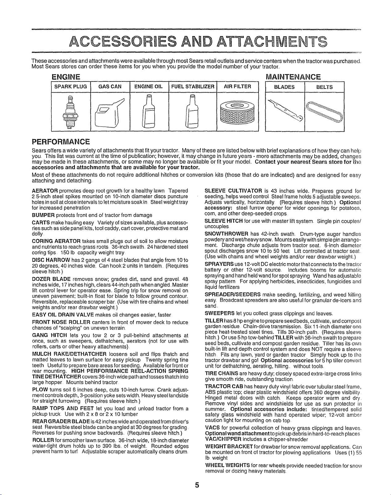
ENGINE MAINTENANCE
SPARK PLUG GAS CAN ENGINE OIL FUEL STABILIZER AIR FILTER
BLADES BELTS
PERFORMANCE
Sears offers a wide variety of attachments that fit your tractor. Many of these are listed below with brief explanations of how they can hell_
you. This list was current at the time of publication; however, it may change in future years - more attachments may be added, change°
may be made in these attachments, or some may no longer be available or fit your model.. Contact your nearest Sears store for the
accessories and attachments that are available for your tractor.
Most of these attachments do not require additional hitches or conversion kits (those that do are indicated) and are designed for easy
attaching and detaching.
AERATOR promotes deep root growth for a healthy lawn Tapered
2 54nch steel spikes mounted on 10-inch diameter discs puncture
holes in soil at close intervals to let moisture soak in Steel weight tray
for increased penetration
BUMPER protects front end of tractor from damage
CARTS make hauling easy Variety of sizes available, plus accesso-
ries such as side panel kits, tool caddy, cart cover, protective mat and
dolly.
CORING AERATOR takes small plugs out of soil to allow moisture
and nutrients to reach grass roots 36-inch swath.. 24 hardened steel
coring tips. t50 Ib capacity weight tray
DISC HARROW has 2 gangs of 4 steel blades that angle from 10 to
20 degrees, 40 incheswide.. Can hook 2 units in tandem. (Requires
sleeve hitch.)
DOZER BLADE removes snow; grades dirt, sand and gravel. 48
inches wide, 17inches high, clears 44-inch path when angled. Master
lift control lever for operator ease.. Spring trip for snow removal on
uneven pavement; built-in float for blade to follow ground contour,
Reversible, replaceable scraper bar (Use with tire chains and wheel
weights and/or rear drawbar weight,)
EASY OIL DRAIN VALVE makes oil changes easier, faster.
FRONT NOSE ROLLER canters in front of mower deck to reduce
chances of "scalping" on uneven terrain.
GANG HITCH lets you tow 2 or 3 pull-behind attachments at
once, such as sweepers, dethatchers, aerators (not for use with
rollers, carts or other heavy attachments)
MULCH RAKFJDETHATCHER loosens soil and flips thatch and
matted leaves to lawn surface for easy pickup Twenty spring line
teeth Useful to prepare bare areas for seeding. Available for front or
rear mounting, HIGH PERFORMANCE REEL-ACTION SPRING
TINE DETHATCHER covers 36-inch wide path and tosses thatch into
large hopper Mounts behind tractor
PLOW turns soil 6 inches deep, cuts lO-inch furrow.. Crank adjust-
ment controls depth, 3-position yoke sets width, Heavy steel landside
for straight furrowing (Requires sleeve hitch)
RAMP TOPS AND FEET let you load and unload tractor from a
pickup truck Use with 2 x 8 or 2 x I0 lumber
REAR GRADER BLADE is42 incheswide and operated from driver's
seat Reversible steel blade can be angled at 30 degrees for grading
Reverses for pushing snow backwards. (Requires sleeve hitch)
ROLLER for smoother lawn surface, 36-inch wide, 18-inch diameter
water4ight drum holds up to 390 Ibs, of weight. Rounded edges
prevent harm to turf Adjustable scraper automatically cleans drum
SLEEVE CULTIVATOR is 43 inches wide. Prepares ground for
seeding, helps weed control, Steel frame holds 5 adjustable sweeps.
Adjusts vertically, horizontally (Requires sleeve hitch.) Optional
accessory; steel furrow opener for wider openings for potatoes,
corn, and other deep-seeded crops
SLEEVE HITCH for use with master lift system, Single pin couples/
uncouples
SNOWTHROWER has 42qnch swath. Drum4ype auger handles
powdery and wet/heavy snow., Mounts easily with simple pin arrange-
ment.. Discharge chute adjusts from tractor seat.. 6-inch diameter
spout discharges snow 10 to 50 feet Lift controlled at tractor seat.
(Use with chains and wheel weights and!or rear drawbar weight.)
SPRAYERS use 12-volt DC electric motor that connects to the tractor
battery or other 12-volt source, Includes booms for automatic
spraying and hand held wand for spot spraying Wand has adjustable
spray pattern For applying herbicides, inseclicides, fungicides and
liquid fertilizers
SPREADER/SEEDERS make seeding, fertilizing, and weed killing
easy. Broadcast spreaders are also useful for granular de-icers and
sand.
SWEEPERS let you collect grass clippings and leaves..
TILLER has 8 hp engine to prepare seed beds, cultivate, and cornpost
garden residue Chain-drive transmission.. Six 11-inch diameterone
piece heat-treated steel tines, Tills 30-inch path (Requires sleeve
hitch) Or use 5 hp tow-behind TtLLER with 36-inch swath to prepare
seed beds, cultivate and compost garden residue. Tiller has its own
built4n lift and depth control system and does NOT require a sleeve
hitch Fits any lawn, yard or garden tractor Simply hook up to the
tractor drawbar and go! Optional accessories for 5 hp tillerconverl
unit for dethatching, aerating, hilling., without tools.
TIRE CHAINS are heavy duty; closely spaced extra-large cross links
give smooth ride, outstanding traction.
TRACTOR CAB has heavy duty vinyl fabdc over tubularsteel frame,
ABS plastic top; clear plastic windshield offers 360 degree visibility
Hinged metal doors with catch. Keeps operator warm and dry.
Remove vinyl sides and windshields for use as sun protector in
summer, Optional accessories include: tinted/tempered solid
safety glass windshie[d with hand operated wiper; 12-volt amb£r
caution light for mounting on cab top.
VAOS for powerful collection of heavy grass clippings and leaves.
Optional wand attachmentto pick up debris in hard-to-reach places
VAC/CHIPPER includes a chipper-shredder
WEIGHT BRACKET for drawbar for snow removal applications, Can
be mounted on front of tractor for plowing applications Uses (1) 55
lb weight
WHEEL WEIGHTS for rear wheels provide needed traction for snow
removal or dozing heavy materials
5
......... .. .......... .. . ........ ..... ................ . ...............,,,,,,
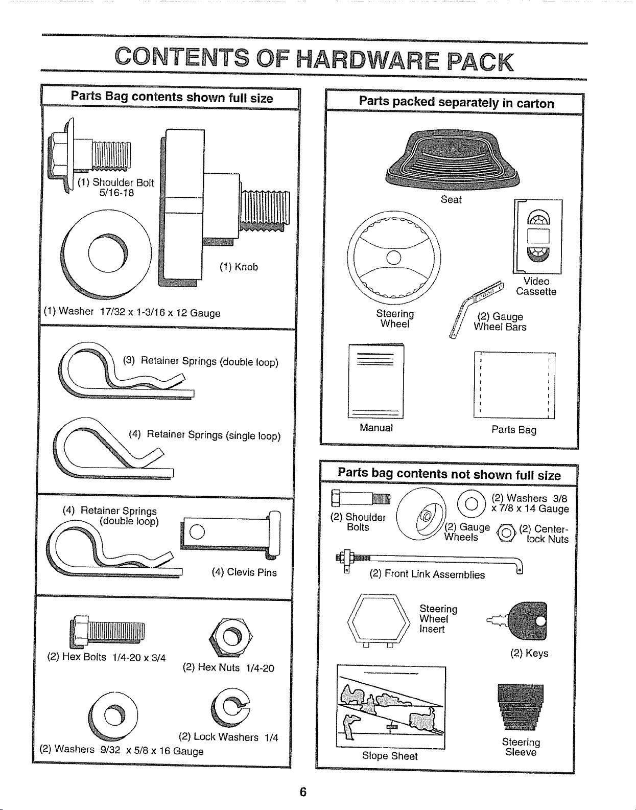
Parts Bag contents shown full size
_J
p____
(1) Shoulder Bolt
5/16-18
(1) Knob
(1) Washer 17/32 x 1-3/16 x 12 Gauge
(4) Clevis Pins
(2) Hex Bolts 1/4-20 x 3/4
(2) Hex Nuts 1/4-20
(2) Lock Washers 1/4
(2) Washers 9/32 x 5/8 x 16 Gauge
Parts packed separately in carton
Steering
Wheel
Manual
Seat
.._,_) Video
_ Cassette
_/ (2) Gauge
Wheel Bars
i ........................ I
Parts Bag
Parts bag contents not shown full size
,,, '........... _1 ......i_ ,,,
/_ f/_ (2)Washers 3t8
(2) Shou{der (_')) ___ xZ/gx14 Gauge
Bolts '\ _i!J(2) Gauge _(2) Center_
_ Wheels _r lock Nuts
_(2) Front Link Assemblies
Steering
Wheel
Insert
(2) Keys
Steering
Sleeve
Slope Sheet
6
LY
Your new tractor has been assembled at the factorywith the exception of those parts left unassembled for shipping purposes.
To ensure safe and proper operation of your tractor all parts and hardware you assemble must be tightened securely. Use
the correct tools as necessary to insure proper tightness°
TOOLS REQUIRED FOR ASSEMBLY
A socket wrench set will make assembly easier.. Standard
wrench sizes are listed.
(2) 7/16" wrenches Tire pressure gauge
(1) 1/2" wrench Utility knife
(1) 9/16" wrench
(1) 3/4" socket with drive ratchet
When right or left hand is mentioned in this manual, it
means when you are in the operating position (seated
behind the steering wheel)_
TO REMOVE TRACTOR FROM CARTON
UNPACK CARTON
o Remove all accessible loose parts and parts cartons
from carton (See page 6).
= Cut, from top to bottom, along lines on all four corners
of carton, and lay panels flat.
= Check for any additional loose parts or cartons and
remove.
BEFORE ROLLING TRACTOR OFF SKID
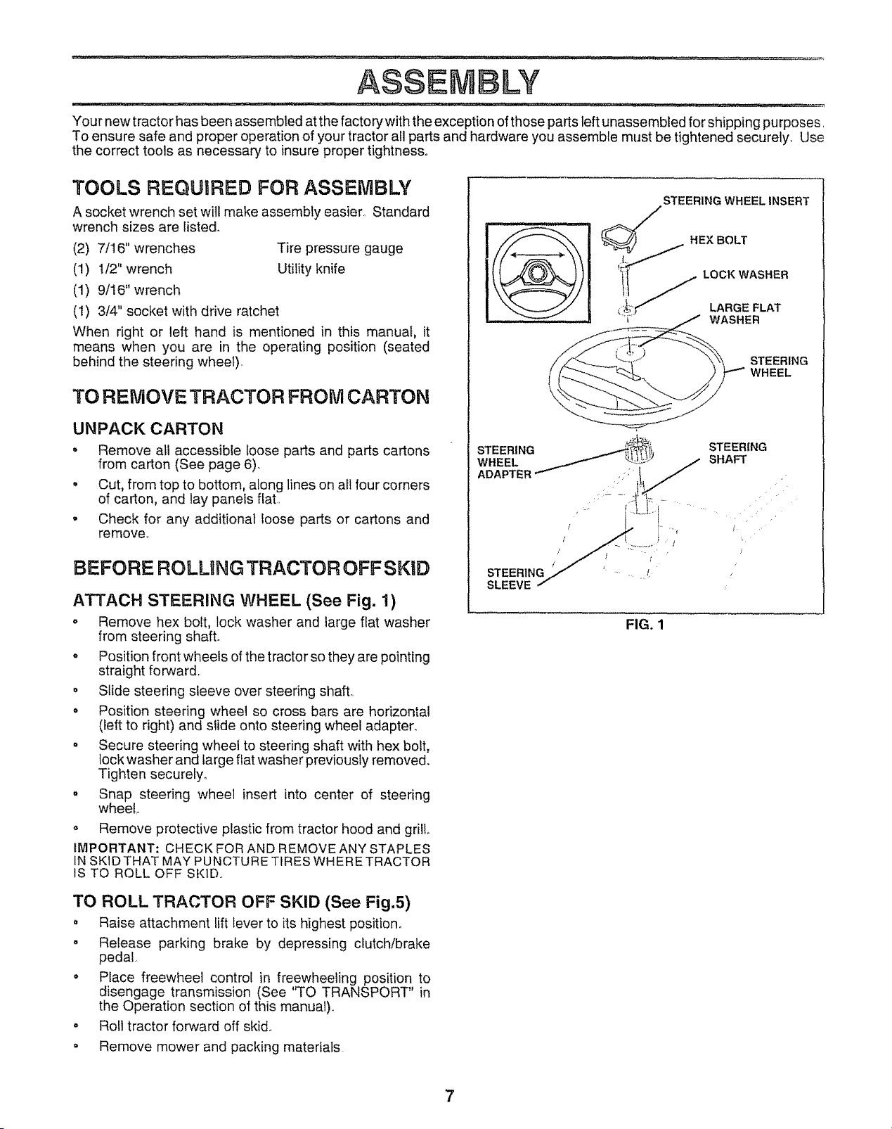
ATTACH STEERING WHEEL (See Fig. 1)
° Remove hex bolt, lock washer and large flat washer
from steering shaft.
Position front wheels of the tractor so they are pointing
straight forward,.
o Slide steering sleeve over steering shafL
o Position steering wheel so cross bars are horizontal
(left to right) and siide onto steering wheel adapter°
o Secure steering wheel to steering shaft with hex bolt,
lock washer and large fiat washer previously removed.
Tighten securely°
. Snap steering wheel insert into center of steering
wheel
o Remove protective plastic from tractor hood and grill,.
IMPORTANT: CHECK FOR AND REMOVE ANY STAPLES
IN SK1DTHAT MAY PUNCTURETIRES WHERE TRACTOR
IS TO ROLL OFF SKID..
STEERING WHEEL INSERT
WASHER
STEERING
WHEEL
STEERING
WHEEL
ADAPTER
STEERING
SLEEVE
/
STEERING
SHAFT
/
FIG. 1
TO ROLL TRACTOR OFF SKID (See Fig.5)
= Raise attachment lift lever to its highest position.
o Release parking brake by depressing clutch/brake
pedaL.
° Place freewheel control in freewheeling position to
disengage transmission (See 'H'O TRANSPORT" in
the Operation section of this manual).
o Ro!l tractor forward off skid.
° Remove mower and packing materials
7
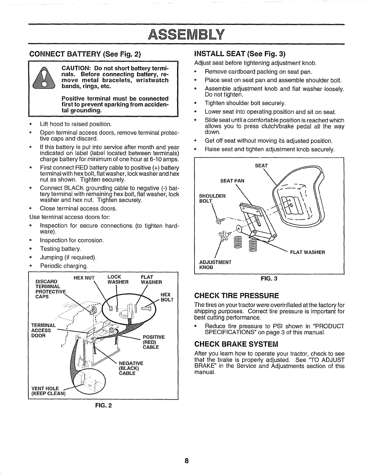
CONNECT BATI'ERY (See Fig. 2)
r,ll i , ill ,,_,,_H ,_/ ii
CAUTION: Do not short battery termi-
nals. Before connecting battery, re-
move metal bracelets, wristwatch
bands, rings, etc.
Positive terminal must be connected
first to prevent sparking from acciden-
tal grounding.
,,,.,, ,,, ,,,
• Lift hood to raised position..
o Open terminal access doors, remove termina] protec-
tive caps and discard.
. If this battery is put into service after month and year
indicated on label (label located between terminals)
charge battery for' minimum of one hour at 6-10 amps.
° First connect RED battery cable to positive (+) battery
terminal with hex bolt, flat washer, lockwasher and hex
nut as shown.. Tighten securely.,
° Connect BLACK grounding cable to negative (-) bat°
tery terminai with remaining hex bolt, flat washer, lock
washer and hex nuL Tighten securely.
° Close terminal access doors.
Use terminal access doors for:
= Inspection for secure connections (to tighten hard-
ware).
° Inspection for corrosion..
° Testing battery.
° Jumping (if required)..
° Periodic charging.,
HEX NUT LOCK
DISCARD WASHER
TERMINAL
PROTECTIVE
CAPS ::_._,_
TERMINAL ,"'" _l
ACCESS
DOOR
FLAT
WASHER
HEX
POSITIVE
(RED)
CABLE
NEGATIVE
(BLACK)
CABLE
VENT HOLE
(KEEP CLEAN)
FIG. 2
INSTALL SEAT (See Fig. 3)
Adjust seat before tightening adjustment knob_
° Remove cardboard packing on seat pan_
o Place seat on seat pan and assemble shoulder bolt.
° Assemble adjustment knob and flat washer toosely.
Do not tighten.
. Tighten shoulder bolt securely.,
° Lower seat into operating position and sit on seal
° Slide seat until a comfortable position is reached which
allows you to press dutch/brake pedal all the way
down,,
° Get off seat without moving its adjusted position.
- Raise seat and tighten adjustment knob securely.
SEAT PAN
SHOULDER
BOLT
SEAT
ADJUSTMENT
KNOB
FIG. 3
FLAT WASHER
CHECK TIRE PRESSURE
The tires on your' tractor were overinflated at the factory for
shipping purposes_ Correct tire pressure is important for
best cutting performance.
° Reduce tire pressure to PSI shown in "PRODUCT
SPECIFICATIONS" on page 3 of this manual
CHECK BRAKE SYSTEM
After you learn how to operate your tractor, check to see
that the brake is properly adjusted., See "TO ADJUST
BRAKE" in the Service and Adjustments section of this
manual.,
8
ASSEM LY
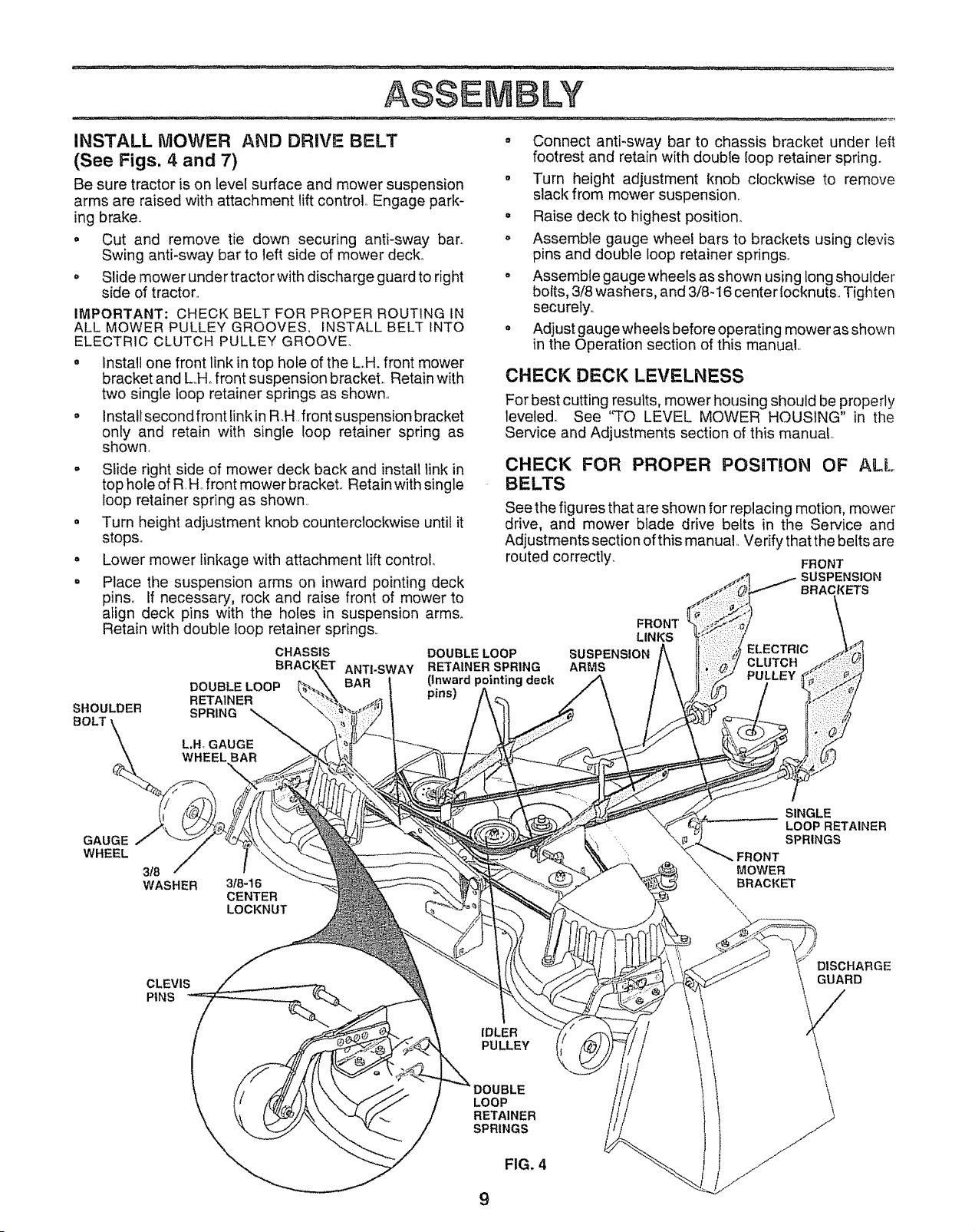
INSTALL MOWER AND DRIVE BELT • Connect anti-sway bar to chassis bracket under left
(See Figs. 4 and 7) footrest and retain with double {oop retainer spring.
Be sure tractor is on level surface and mower suspension • Turn height adjustment knob clockwise to remove
arms are raised with attachment lift control_ Engage park- slack from mower suspension,
ing brake., ° Raise deck to highest position.
. Cut and remove tie down securing anti-sway barn o Assemble gauge wheel bars to brackets using clevis
Swing anti-sway bar to left side of mower deck. pins and double loop retainer springs,
o Slide mower under tractorwith discharge guard to right o Assemble gauge wheels as shown using long shoulder
side of tractor., bolts, 3/8 washers, and 3/8-16 center iocknuts., Tighten
securely,,
. Adjust gauge wheels before operating mower as shown
in the Operation section of this manual,,
IMPORTANT: CHECK BELT FOR PROPER ROUTING IN
ALL MOWER PULLEY GROOVES, INSTALL BELT INTO
ELECTRIC CLUTCH PULLEY GROOVE_
° Install one front link in top hole of the L.H. front mower
bracket and L.,Hofront suspension bracket.. Retain with
two single loop retainer springs as shown.,
° Install second front linkin R,,H,front suspension bracket
only and retain with single Ioop retainer spring as
shown.
o Slide right side of mower deck back and install link in
top hole of R,H.,front mower bracket Retain with single
loop retainer spring as shown..
• Turn height adjustment knob counterclockwise until it
stops.
. Lower mower linkage with attachment lift control.
• Place the suspension arms on inward pointing deck
pins,, If necessary, rock and raise front of mower to
align deck pins with the holes in suspension arms°
Retain with double loop retainer springs.,
SHOULDER
CHASSIS
BRACl ET ANTI-SWAY
DOUBLE LOOP
RETAINER
SPRING
CHECK DECK LEVELNESS
For best cutting results, mower housing should be properly
leveled_ See 'q'O LEVEL MOWER HOUSING" in the
Service and Adjustments section of this manual,.
CHECK FOR PROPER POSUT!ON OF ALL
BELTS
See the figures that are shown for replacing motion, mower
drive, and mower blade drive belts in the Service and
Adjustments section of this manual, Verify that the belts are
routed correctly,. FRONT
SUSPENSION
BRACKETS
DOUBLE LOOP
RETAINER SPRING
(inward pointing deck
pins)
ARMS
FRONT
LINKS
ELECTRIC
CLUTCH
PULLEY
L,H, GAUGE
WHEEL BAR
GAUGE
WHEEL
3f8
WASHER
318-16
CENTER
LOCKNUT
SINGLE
LOOP RETAINER
SPRINGS
FRONT
MOWER
BRACKET
CLEVIS
PINS
IDLER
PULLEY
DISCHARGE
GUARD
LOOP
RETAINER
SPRINGS
FIG. 4
9
,/CHECKLIST
BEFORE YOU OPERATE AND ENJOY YOUR NEW
TRACTOR, WE WISH TO ASSURE THAT YOU RECEIVE
THE BES T PERFORMANCE AND SA TISFA CTION FROM
THIS QUALITY PRODUCT,
PLEASE REVIEW THE FOLLOWING CHECKLIST:
,/ All assembly instructions have been completed.
,! No remaining loose parts in carton..
,/ Battery is properly prepared and chmged. (Minimum
1 hour at 6 amps)..
,/ Seat is adjusted comfortably and tightened securely.
v" All tires are properly inflated. (Forshipping purposes,
the tires were overinflated at the factory)°
,/ Be sure mower deck is properly leveled side-to-side/
front-to-rear for best cutting results. (Tires must be
properly inflated for teveling)_
J' Check mower and drive belts_ Be sure they are routed
properly around pulleys and inside all belt keepers..
J Check wiring.. See that all connections are still secure
and wires are properly clamped..
WHILE LEARNING HOW TO USE YOUR TRACTOR,
PA Y EXTRA A TTENTION TO THE FOLL OWING IMPOR-
TANT ITEMS.:
,I Engine oil is at proper level..
,/ Fuel tank is filled with fresh, clean, regular unleaded
gasoline.
,/ Become familiar with all controls - their location and
function_ Operate them before you start the engine.
,/ Be sure brake system is in safe operating condition..
10

........ - - ......... -- --_....................... i,,,,ii i.., Ill :,,i ........................ , _*_--._._:_
OPERATHO
These symbols may appear on your tractor or in literature supplied with the producL Learn and understand their meaniny.
BATTERY CAUTION OR REVERSE FORWARD FAST SLOW
WARNING
ENGINE ON ENGINE OFF OIL PRESSURE CLUTCH LIGHTS ON LIGHTS OFF
CHOKE MOWER HEIGHT DIFFERENTIALFU EL UNLOCKED
PARKING BRAKE
LOCKEDLOCK
REVERSE NEUTRAL HIGH LOW
PARKING BRAKE
MOWER LIFT
ATTACHMENT
CLUTCH ENGAGED
ATTACHMENT
CLUTCH DISENGAGED
IGNITION
DANGER, KEEP HANDS AND FEET AWAY
HYDROSTATIC FREE WHEEL
(Hydro Models only)
'I '1
OffERATION
:. ill ¸ ........ i, ................................ /: .....................
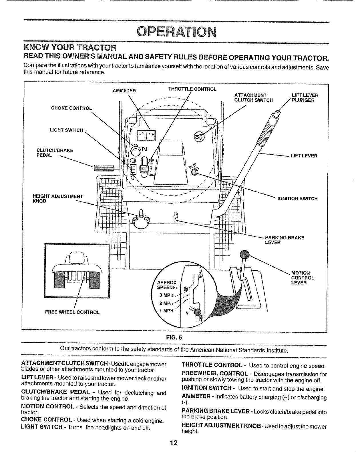
KNOW YOUR TRACTOR
READ THIS OWNER'S MANUAL AND SAFETY RULES BEFORE OPERATING YOUR TRACTOR.
Compare the illustrationswith your tractor to familiarize yourself with the location of various controls and adjustments. Save
this manual for future reference°
CHOKE CONTROL
LIGHT SWITCH
CLUTCH/BRAKE
PEDAL
HEIGHT ADJUSTMENT
KNOB
AMMETER
THROTTLE CONTROL
ATTACHMENT
..... CLUTCH SWITCH
LIFT LEVER
LIFT LEVER
IGNITION SWITCH
PARKING BRAKE
LEVER
FREE WHEEL CONTROL
APPROX.
SPEEDS:
3
2
\
MOTION
CONTROL
LEVER
FIG. 5
Our tractors conform to the safety standards of the American National Standards Institute.
ATTACHMENT CLUTCH SWITCH- Used to engage mower
blades or other' attachments mounted to your tractor°
LIFT LEVER - Used to raise and lower mowerdeck orother
attachments mounted to your tractor,,
CLUTCHtBRAKE PEDAL - Used for declutching and
braking the tractor and starting the engine,
MOTION CONTROL - Selects the speed and direction of
tractor_,
CHOKE CONTROL - Used when starting a cold engine,
LIGHT SWITCH - Turns the headlights on and off,
THROTTLE CONTROL - Used to control engine speed.
FREEWHEEL CONTROL - Disengages transmission for
pushing or slowly towing the tractor with the engine off.
IGNITION SWITCH - Used to start and stop the engine,
AMMETER - Indicates battery charging (+) or discharging
(-).
PARKING BRAKE LEVER - Locks clutch/brake pedal into
the brake position,
HEIGHT ADJUSTMENT KNOB- Used to adjust the mower
height,.
12
OPERATI ON
HOW TO USE YOUR TRACTOR
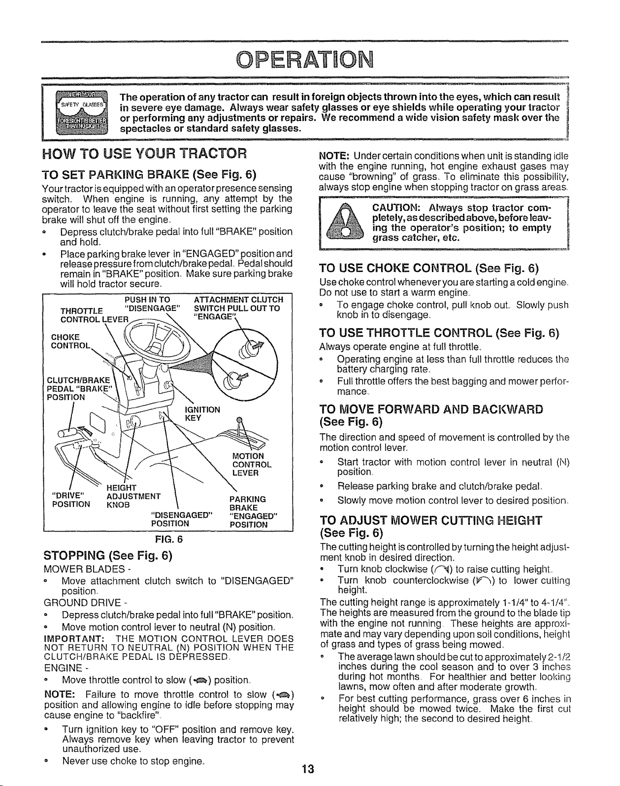
TO SET PARKING BRAKE (See Fig. 6)
Your tractor is equipped with an operator presence sensing
switch., When engine is running, any attempt by the
operator to leave the seat without first setting the parking
brake will shut off the engine_
= Depress clutch/brake pedal into full "BRAKE" position
and hold..
• Place parking brake lever in "ENGAGED" position and
release pressu re from clutch/brake pedal.. Pedal should
remain in "BRAKE" position., Make sure parking brake
will hold tractor secure.
PUSH IN TO ATTACHMENT CLUTCH
THROTTLE "DISENGAGE" SWITCH PULL OUT TO
CONTROL LEVER
CHOKE
CONTROL
CLUTCHIBRAKE
PEDAL "BRAKE"
POSITION
IGNITION
MOTION
CONTROL
LEVER
HEIGHT
"DRIVE" ADJUSTMENT PARKING
POSITION KNOB BRAKE
"DISENGAGED .... ENGAGED"
POSITION POSITION
FIG. 6
STOPPING (See Fig. 6)
MOWER BLADES -
o Move attachment clutch switch to "DISENGAGED"
position_
GROUND DRIVE-
° Depress clutch/brake pedal into full "BRAKE" position_
° Move motion control lever to neutral (N) position_
IMPORTANT: THE MOTION CONTROL LEVER DOES
NOT RETURN TO NEUTRAL (N) POSITION WHEN THE
CLUTCH/BRAKE PEDAL fS DEPRESSED..
ENGINE -
o Move throttle control to slow (,_,) position.
NOTE: Failure to move throttle control to slow (,,_)
position and allowing engine to idle before stopping may
cause engine to "backfire",
= Turn ignition key to "OFF" position and remove key.
Always remove key when leaving tractor to prevent
unauthorized use.
o Never use choke to stop engine,.
13
NOTE: Under certain conditions when unit is standing idle
with the engine running, hot engine exhaust gases may
cause "browning" of grass. To eliminate this possibility,
always stop engine when stopping tractor on grass areas.
TO USE CHOKE CONTROL (See Fig. 6)
Use choke control whenever you are starting a cold engine.
Do not use to start a warm engine..
= To engage choke control, pull knob out.. Slowly push
knob in to disengage,
TO USE THROTTLE CONTROL (See Fig. 6)
Always operate engine at full throttle.,
• Operating engine at less than futt throttle reduces tlne
battery charging rate.
= Full throttle offers the best bagging and mower perfor-
mance..
TO MOVE FORWARD AND BACKWARD
(See Fig, 6)
The direction and speed of movement is controlled by the
motion control lever.
° Start tractor with motion control lever in neutral (N)
position.
° Release parking brake and clutch!brake pedal.,
o Slowly move motion control lever to desired position.
TO ADJUST IVIOWER CUTTING HEIGHT
(See Fig. 6)
The cutting height is controlled by turning the height adjust-
ment knob in desired direction_
o Turn knob clockwise (F_) to raise cutting height..
= Turn knob counterclockwise (_)to lower cutting
heighL
The cutting height range is approximately 1-1/4" to 4-1/4'L
The heights are measured from the ground to the blade tip
with the engine not running. These heights are approxi-
mate and may vary depending upon soil conditions, height
of grass and types of grass being mowed,
o The average lawn should be cut to approximatefy 2-1/2
inches during the cool season and to over 3 inctles
during hot months. For healthier and better looking
lawns, mow often and after moderate growth.
o For best cutting performance, grass over 6 inches in
height should be mowed twice.. Make the first cut
relatively high; the second to desired height°
OPERAT Of
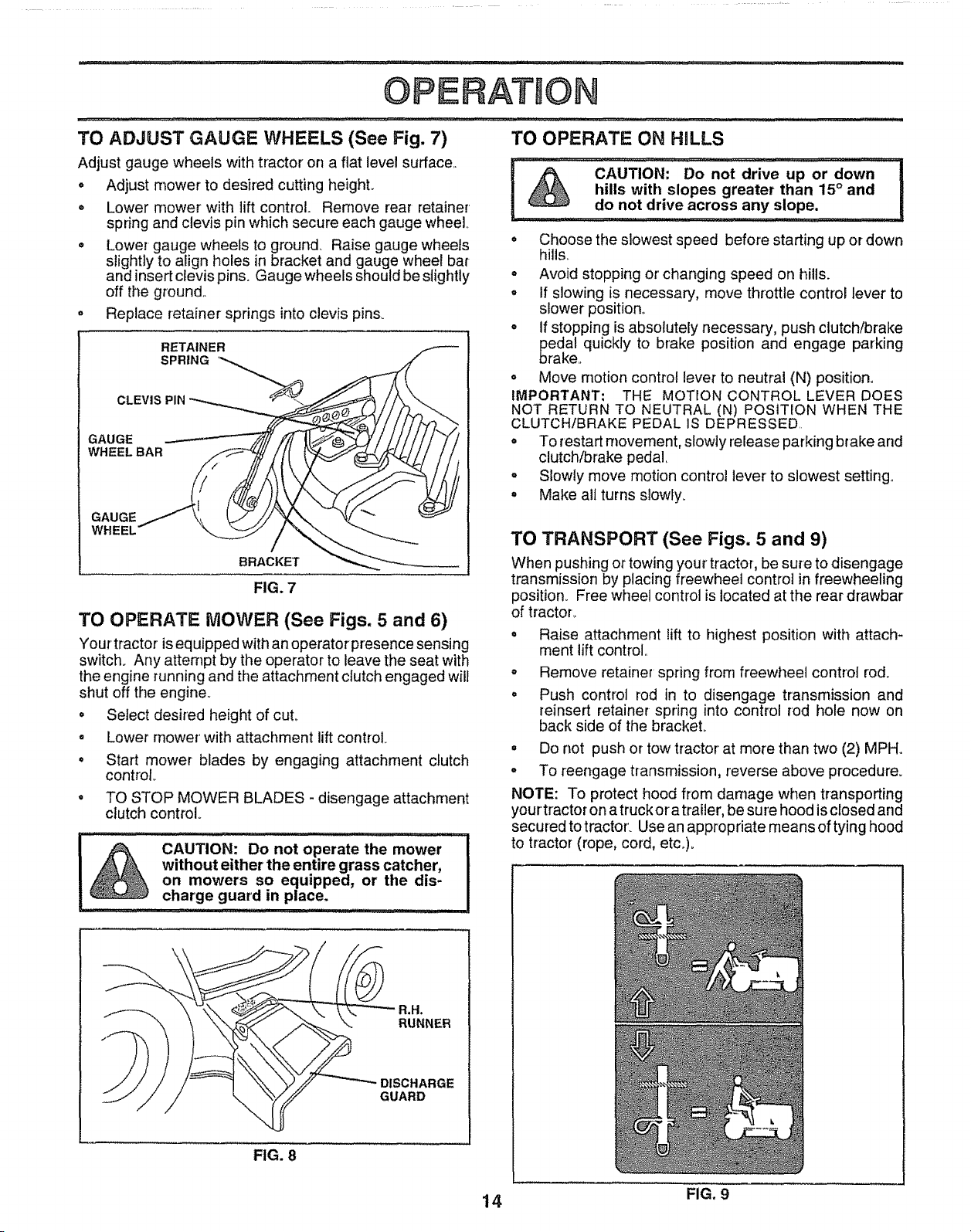
TO ADJUST GAUGE WHEELS (See Fig. 7)
Adjust gauge wheels with tractor on a flat level surface..
o
o
Adjust mower to desired cutting height..
Lower mower with lift control. Remove rear retainer
spring and clevis pin which secure each gauge wheel..
o Lower gauge wheels to ground. Raise gauge wheels
slightly to align holes in bracket and gauge wheel bar
and insert clevis pins° Gauge wheels should be slightly
off the ground..
o Replace retainer springs into clevis pins_
RETAINER
SPRING '_
CLEVI. _
GAUGE
WHEELBAR
GAUGE
WHEEL
BRACKET
FIG. 7
TO OPERATE MOWER (See Figs. 5 and 6)
Your tractor is equipped with an operator presence sensing
switch. Any attempt by the operator to leave the seat with
the engine running and the attachment clutch engaged will
shut off the engine..
o Select desired height of cut.
Lower mower' with attachment lift control
°
o
Start mower blades by engaging attachment clutch
control
TO STOP MOWER BLADES - disengage attachment
clutch control.
-/ ............................ i /i i/ . ii, i,illll , ,i, IH' IIIIIHlll
CAUTION: Do not operate the mower
without either the entire grass catcher,
on mowers so equipped, or tile dis-
charge guard in place.
i,,i, i/r,,: , _ ......... ii ill i,,
TO OPERATE ON HnLLS
,u ,- i ,ll,,ll,,,i ll,,, ii ............ i,, ,, i ii,l,i
CAUTION: Do not drive up or down !
hills with slopes greater than 15 ° and
' do not drive across any slope, i
, Choose the slowest speed before starting up or down
hills..
o Avoid stopping or' changing speed on hills.
° If slowing is necessary, move throttle control lever to
slower position°
• If stopping is absolutely necessary, push clutch/brake
edal quickly to brake position and engage parking
rake..
° Move motion control lever to neutral (N) position.
IMPORTANT; THE MOTION CONTROL LEVER DOES
NOT RETURN TO NEUTRAL (N) POStTION WHEN THE
CLUTCH/BRAKE PEDAL IS DEPRESSED.
° To restart movement, stowlyrelease parking brake and
clutch/brake pedal,
° SIowty move motion control lever to slowest setting..
° Make sit turns slowly_
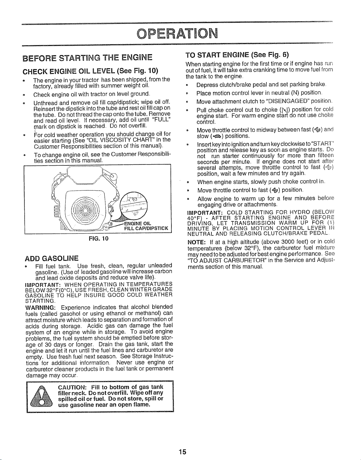
TO TRANSPORT (See Figs. 5 and 9)
When pushing or towing your tractor, be sure to disengage
transmission by placing freewheel contro] in freewheeling
position_ Free wheel control is located at the rear drawbar
of tractoL
o Raise attachment tift to highest position with attach-
ment lift control..
o
o
Remove retainer spring from freewheel control rod.
Push control rod in to disengage transmission and
reinsert retainer spring into control rod hole now on
back side of the brackeL
° Do not push or tow tractor at more than two (2) MPHo
= To reengage transmission, reverse above procedure.
NOTE: To protect hood from damage when transporting
yourtractor on a truckor a trailer, be sure hood is closed and
secured to tractor. Use an appropriate means of tying hood
to tractor (rope, cord, etc.,).
\
\
DISCHARGE
GUARD
FIG. 8
t4 FIG. 9
OPERATaO
BEFORE STAIRTRNG THE ENGINE
CHECK IENGgNE OIL LEVEL (See Fig. 10)
° The engine in yourtractor has been shipped, from the
factory, already filled with summer weight oil.
o Check engine oil with tractor on level ground.
• Unthread and remove oil fit! cap/dipstick; wipe oil off.
Reinsert the dipstick into the tube and rest oil fill cap on
the tube. Do not thread the cap onto the tube. Remove
and read oil level, If necessary, add oil until "FULL"
mark on dipstick is reached., Do not overfill
° For cold weather operation you should change oil for
easier starting (See "OIL VISCOSITY CHART in the
Customer Responsibilities section of this manual),.
° To change engine oil, see the Customer Responsibili-
ties section in this manual,,
ADD GASOLINE
- Fill fuel tank,, Use fresh, clean, regular unleaded
gasoline. (Use of leaded gasoline will increase carbon
and lead oxide deposits and reduce valve life)_
IMPORTANT: WHEN OPERATING IN TEMPERATURES
BELOW 32°F(0°C), USE FRESH, CLEAN WINTER GRADE
GASOLINE TO HELP INSURE GOOD COLD WEATHER
STARTING,,
WARNING: Experience indicates that alcohol blended
fuels (called gasohol or using ethanol or methanol) can
attract moisture which leads to separation and formation of
acids during storage,, Acidic gas can damage the fuel
system of an engine while in storage. To avoid engine
problems, the fuel system should be emptied before stor-
age of 30 days or longer.. Drain the gas tank, start the
engine and let it run until the fuel lines and carburetor are
empty. Use fresh fuel next season. See Storage Instruc-
tions for additional information., Never use engine or
carburetor cleaner products in the fuel tank or permanent
damage may occur.
TO START ENGINE (See Fig. 6)
When starting engine for the first time or if engine has run
out of fuel, it will take extra cranking time to move fuel from
the tank to the engine,.
= Depress clutch/brake pedal and set parking brake
. Place motion control lever in neutra! (N) position.
° Move attachment clutch to "DISENGAGED" position.
° Pull choke control out to choke (t\{) position for cold
engine start,, For warm engine start do not use choke
control.
o Move throttle control to midway between fast (,¢_) and
slow (,e_.) positions.
o Insert key into ignition and turn key clockwise to"START"
position and release key as soon as engine starts. Do
not run starter continuously for more than fifteen
seconds per minute. If engine does not start after
several attempts, move throttle control to fast (,_:._)
position, wait a few minutes and try again_
° When engine starts, slowly push choke control in..
° Move throttle control to fast (@) position..
• Allow engine to warm up for a few minutes before
engaging drive or attachments..
IMPORTANT: COLD STARTING FOR HYDRO (BELOW
40°1=) - AFTER STARTING ENGINE AND BEFORE
DRIVING, LET TRANSMISSION WARM UP FOR (t)
MINUTE BY PLACING MOTION CONTROL LEVER IN
NEUTRAL AND RELEASING CLUTCH/BRAKE PEDAL.
NOTE: If at a high altitude (above 3000 feet) or in cold
temperatures (below 32°F), the carburetor fuel mixture
may need to be adjusted for best engine performance., See
'q-O ADJUST CARBURETOR" in the Service and Adjus_-
merits section of this manual,,
15
OPEF ATUON
PURGE TRANSMISSION
CAUTION: Neverengage or disengage
freewheel lever while the engine is run-
ning_
To ensure proper operation and performance, it is recom-
mended that the transmission be purged before operating
tractor for the first time,. This procedure will remove any
trapped air inside the transmission which may have devel-
oped during shipping of your tractor,
IMPORTANT: SHOULD YOUR TRANSMISSION REQUIRE
REMOVAL FOR SERVICE OR REPLACEMENT, tT
SHOULD BE PURGED AFTER REINSTALLATtON
BEFORE OPERATING THE TRACTOR,.
o Place tractor safely on level surface with engine off and
parking brake set,,
o Disengage transmission by placing freewheel cen!rol
in freewheeling position (See 'TO TRANSPORT' in
this section of manuat).
. Sitting in the tractor seat, start engine,, After the engine
is running, move throttle control to slow (,_) position,.
With motion control lever' in neutral (N) position, slowly
disengage clutch/brake pedal
o Move motion control lever to full forward position and
hold for five (5) seconds,, Move lever to full reverse
position and hold for five (5) seconds, Repeat this
procedure three (3) times.
NOTE: During this procedure there will be no movement of
drive wheels,. The air-is being removed from hydraulic drive
system°
. Move motion control leverto neutral (N) position,, Shut-
off engine and set parking brake..
° Engage transmission by placing freewheel control in
driving position (See "TO TRANSPORT" in this section
of manual)..
. Sitting inthetractor seat, start engine. Aftertheengine
is running, move throttle control to half (1/2) speed.
With motion control lever in neutral (N) position, slowly
disengage clutch/brake pedal.
. Slowly move motion control lever forward, after the
tractor moves approximately five (5) feet, slowly move
motion control lever to reverse position,, After the
tractor moves approximately five (5) feet return the
motion control lever to the neutral (N) position. Repeat
this procedure with the motion control lever three (3)
times,,
o Your tractor is now purged and now ready for normal
operation,,
iVlOWING TiPS
o Tire chains cannot be used when the mower housing is
attached to tractor.
• Mower should be properly leveled for best mowing
performance_ See "TO LEVEL MOWER HOUSING" in
the Service and Adjustments section of this manual,.
o Use the runner on the right hand side of mower as a
guide,, The blade cuts approximately an inch outside
the runner (See Fig. 8).
° The left hand side of mower should be used for trirn-
ming_
" Drive so that clippings are discharged onto the area
that has been cuL Have the cut area to the right of the
tractor_ This will result in a rnore even distribution of
clippings and more uniform cutting,,
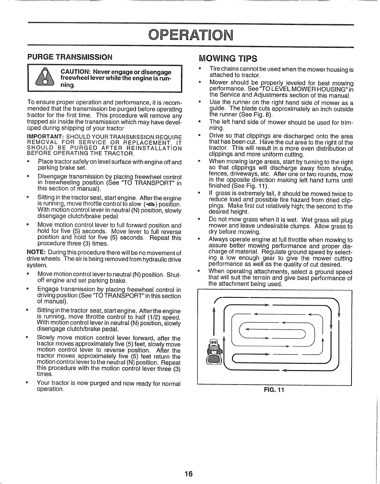
o When mowing large areas, start by turning to the right
so that clippings will discharge away from shrubs,
fences, driveways, etc,, After one or two rounds, mow
in the opposite direction making left hand turns until
finished (See Fig. 11)_
° If grass is extremely tall, it should be mowed twice to
reduce load and possible fire hazard from dried clip-
pings,. Make first cut relatively high; the second to the
desired heighL
" Do not mow grass when it is weL Wet grass will plug
mower and leave undesirable clumps Allow grass to
dry before mowing.
o Always operate engine at full throttle when mowing to
assure better' mowing performance and proper dis-
charge of material. Regulate ground speed by select-
mg a low enough gear to give the mower cutting
performance as well as the quality of cut desired.
° When operating attachments, select a ground speed
that will suit the terrain and give best performance of
the attachment being used.
f
FIG. 11
16
Check Brake Operation
Check Tire Pressure
"[ Check for Loose Fasteners
sharpen/'Replace Mower Blades
C Lubrication Chart ............
T Check Battery Leve.i{aechar.ge
0 C{ean Battery and Terminals
R CheckTransaxle Cooling
Adjust Blade Belt(s) Tension
Adjust Motion Drive Belt(s) Tension
...............
j .............
Check Engine Oil Level _' 6#4
CHangeEngine Oi!.................. _#' LI _2,3[ ..... 6#4
Clean Air Filter
E ...................................... ..............
a cleanAir Screen..................... ............. ...............
G Inspect Muffler/Spark Arrester .........
I ReplaceOil Filter (If equipped) .........
N Clean.Engine .....
Fins
Replace Spark Plug .........
Replace Air Filter Paper Cartridge .......
Replace Fuei FiIter
: . ......... ,..
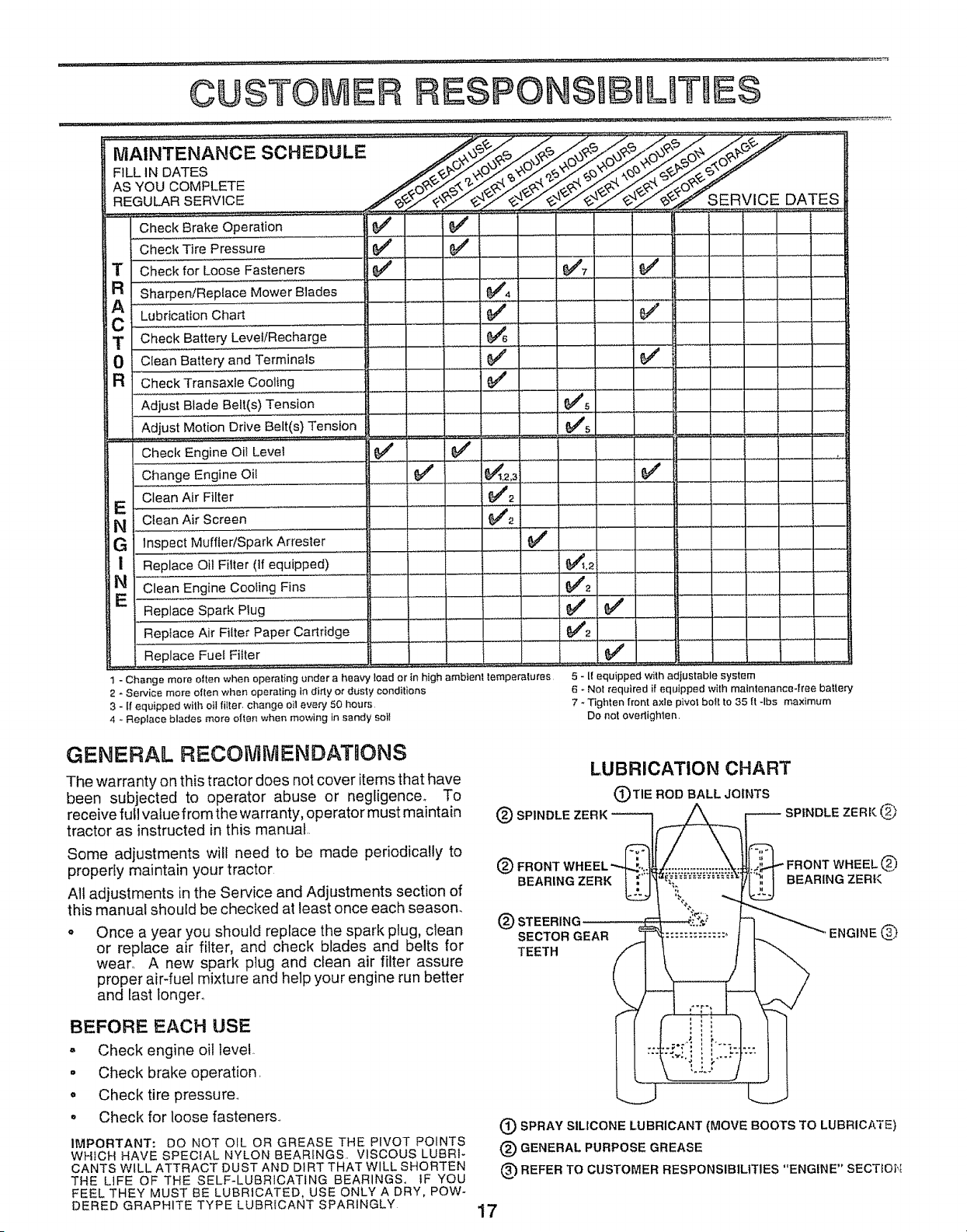
1 - Change more otten when operating under a heavy teed or in high ambient _emperetures
2 - Service more otten when operating in dirty or dusty conditions
3 - If equipped wilh oil fitter, change oil every 50 hours
4 - Replace blades more often when mowing in sandy soil
5 - 11equipped with adiustable system
6 - Not required if equipped with maintenance4ree battery
7 - Tighten front axte pivot bo_t to 35 ft -Ibs maximum
Do not overtighten,
GENERAL RECOtVtMENDATQONS
The warranty on this tractor does not cover items that have
been subjected to operator abuse or negligence. To
receive full value from the warranty, operator must maintain
tractor as instructed in this manual
Some adjustments will need to be made periodically to
properly maintain your tractor
All adjustments in the Service and Adjustments section of
this manual should be checked at least once each season_
o Once a year you should replace the spark plug, clean
or replace air filter, and check blades and belts for
wear. A new spark plug and clean air filter assure
proper air-fuel mixture and help your engine run better
and last longer..
BEFORE EACH USE
- Check engine oil level
• Check brake operation.
o Check tire pressure..
° Check for loose fasteners..
IMPORTANT: DO NOT OIL OR GREASE THE PIVOT POINTS
WHfCH HAVE SPEC{AL NYLON BEARINGS.. VISCOUS LUBRI-
CANTS WILL ATTRACT DUST AND D_RT THAT WILL SHORTEN
THE LiFE OF THE SELF-LUBRICATING BEARINGS. tF YOU
FEEL THEY MUST BE LUBRICATED, USE ONLY A DRY, POW-
DERED GRAPHITE TYPE LUBRICANT SPARINGLY
(_ SPRAY SILICONE LUBRICANT (MOVE BOOTS TO LUBRICATE)
(_) GENERAL PURPOSE GREASE
_') REFER TO CUSTOMER RESPONSIBIUT1ES "ENGINE" SECTEON
17
CUSTOMER
TRACTOR
Always observe safety rules when performing any mainte-
nance.
BRAKE OPERATION
If tractor requires more than six (6) feet stopping distance
at high speed in highest gear, then brake must be adjusted_
(See "TO ADJUST BRAKE" in the Service and Adjust-
n'lents section of this manua!),
TIRES
o Maintain proper air pressure in all tires (See "PROD-
UCT SPECIFICATIONS" on page 3 of this manual).
o Keep tires free of gasoline, oil, or' insect control chemi-
cals which can harm rubber.
Avoid stumps, stones, deep ruts, sharp objects and
other hazards that may cause tire damage.
BLADE CARE
For best results mower blades must be kept sharF Re-
place bent or damaged blades.
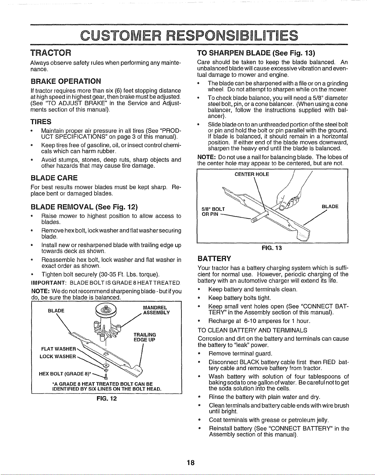
BLADE REMOVAL (See Fig. 12)
o Raise mower to highest position to allow access to
blade&
Remove hex bolt, lock washer and flat washer secu ring
btade_
Install new or resharpened blade with trailing edge up
towards deck as shown°
Reassemble hex belt, lock washer and flat washer in
exact order as shown.
• Tighten bolt securely (30-35 FL Lbs,. torque),,
IMPORTANT: BLADE BOLT IS GRADE 8 HEATTREATED,
NOTE: We do not recommend sharpening blade - but if you
do, be sure the blade is balanced.
*A GRADE 8 HEAT TREATED BOLT CAN BE
IDENTIFIED BY SIX LINES ON THE BOLT HEAD.
FIG, 12
TO SHARPEN BLADE (See Fig. 13)
Care should be taken to keep the blade ba/anced_ An
unbalanced blade will cause excessive vibration and even-
tual damage to mower' and engine_
. The blade can be sharpened with a file or on a grinding
wheel. Do not attempt to sharpen while on the mower..
. To check blade balance, you wil! need a 5/8" diameter
steel bolt, pin, or a cone balancer, (When using a cone
balancer, follow the instructions supplied with bal-
ancer),.
• Slide blade on to an unth readed portion of the steel bolt
or pin and hold the bolt or pin parallel with the ground.
If blade is balanced, it should remain in a horizontal
position_ If either end of the blade moves downward,
sharpen the heavy end until the blade is balance&
NOTE: Do not use a nail for balancing blade° The lobes of
the center hole may appear' to be centered, but are noL
CENTER HOLE
518"BOLT
OR PIN
BLADE
FIG. 13
BATTERY
Your tractor has a battery charging system which is suffi-
cient for normal use. However, periodic charging of the
battery with an automotive charger will extend its life,.
° Keep battery and terminals clean°
° Keep battery bolts tighL
o Keep small vent holes open (See "CONNECT BAT-
TERY" in the Assembly section of this rnanual).
° Recharge at 6-10 amperes for' 1 hour_
TO CLEAN BATTERY AND TERMINALS
Corrosion and dirt on the battery and terminals can cause
the battery to "leak" power'.
• Remove terminal guard.
o Disconnect BLACK battery cable first then RED bat-
tery cable and remove battery from tractor',,
° Wash battery, with solution of four tablespoons of
baking soda to one gallon of water° Be careful not to get
the soda solution into the cell&
° Rinse the battery with plain water and dry,,
o Clean terminals and battery, cable ends with wire brush
until bright.
. Coat terminals with grease or petroleum jelly.
° Reinstall battery" (See "CONNECT BATTERY" in the
Assembly section of this manual),
18
CUSTOME
L ES
TRANSAXLE COOLING
The fan and cooling fins of transmission should be kept
clean to assure proper cooling..
Do not attempt to clean fan or transmission while engine is
running or while the transmission is hot.. To prevent
possible damage to seals, no not use high pressure water
or steam to clean transaxle.
o Inspect cooling fan to be su re fan blades are intact and
clean..
o Inspect cooling fins for dirt, grass clippings and other
materials. To prevent damage to seals, do not use
compressed air or high pressure sprayer..
TRANSAXLE PUMP FLUID
The transaxle was sealed at the factory and fluid mainte-
nance is not required for the life of the transaxle. Should
the transaxle ever teak or require servicing, contact your
nearest authorized service center/department,
V-BELTS
Check V-belts for deterioration and wear after 100 hours of
operation and replace if necessaP/. The belts are not
adjustable_ Replace belts if they begin to slip from wear,,
ENGINE
LUBRICATION
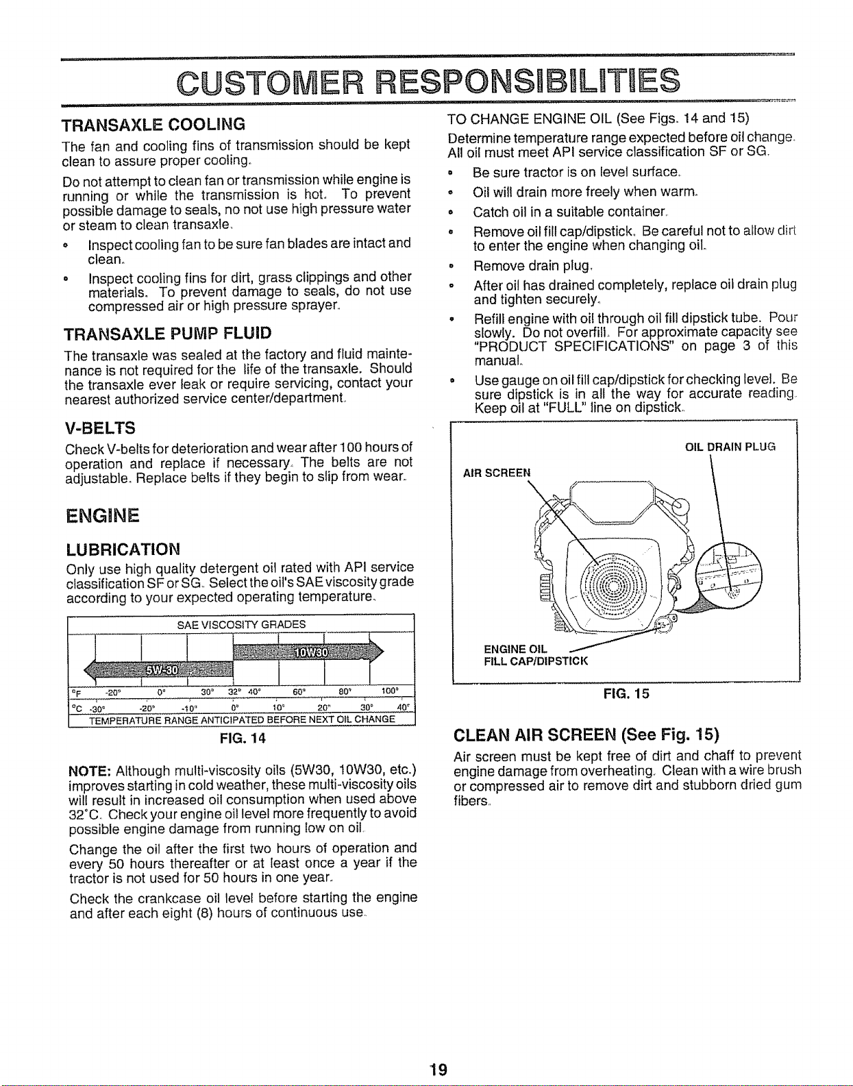
Only use high quality detergent oil rated with API service
classification SF or SG.. Select the oil's SAE viscosity grade
according to your expected operating temperature.
SAE ViSCOSiTY GRADES
I
aF .20 _ 0 _ 30 ° 32 _ 40 ° 60 ° 80 _ 100 °
TEMPERATURE RANGE ANTICIPATED BEFORE NEXT OIL CHANGE
FIG. 14
NOTE: Although multi-viscosity oils (5W30, 10W30, etc.)
improves starting in cold weather, these multi-viscosity oits
wil! result in increased oil consumption when used above
32°C_ Check your engine oil level more frequently to avoid
possible engine damage from running low on oil.
Change the oil after the first two hours of operation and
every 50 hours thereafter or at least once a year if the
tractor is not used for 50 hours in one year_
Check the crankcase oil level before starting the engine
and after each eight (8) hours of continuous use.
TO CHANGE ENGINE OIL (See Figs. 14 and 15)
Determine temperature range expected before oil change.
All oil must meet API service classification SF or SG,
• Be sure tractor is on level surface,.
° Oil will drain more freely when warm°
. Catch oil in a suitable container.
° Remove oil fill cap/dipstick. Be careful not to allow dirt
to enter the engine when changing oil,.
° Remove drain plug,
- After oil has drained completely, replace oit drain plug
and tighten securely.
• Refill engine with oi! through oil fill dipstick tube. Pour
slowly. Do not overfill, For approximate capacity see
"PRODUCT SPECIFICATIONS" on page 3 of this
manual,.
• Use gauge on oil fill cap/dipstick for checking level. Be
sure dipstick is in all the way for accurate reading
"FULL"
Keep oil at line on dipstick..
AIR SCREEN
ENGINE OIL
FILL CAP/DIPSTICK
OIL DRAIN PLUG
FIG. 15
CLEAN AIR SCREEN (See Fig. 15)
Air screen must be kept free of dirt and chaff to prevent
engine damage from overheating, Clean with a wire brush
or compressed air to remove dirt and stubborn dried gum
fibers..
19
¢USTO
CLEAN AIR INTAKE/COOLING AREAS
To insure proper cooling, make sure the grass screen,
cootJng fins, and other external surfaces of the engine are
kept clean at all times,
Every 100 hours of operation (more often under extremely
dusty, dirty conditions), remove the blower housing and
other cooling shrouds_ Clean the cooling fins and external
surfaces as necessary,, Make sure the cooling shrouds are
reinstalled.
NOTE: Operating the engine with a blocked grass screen,
dirty or plugged cooling fins, and!or cooling shrouds re-
moved will cause engine damage due to overheating.
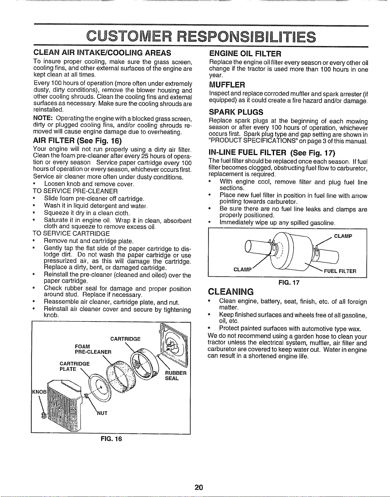
AIR FILTER (See Fig. 16)
Your engine will not run properly using a dirty air filter°
Clean the foam pre-cleaner after every 25 hours of opera-
tion or every season Service paper' cartridge every 100
hours of operation or every season, whichever occurs first..
Service air cleaner more often under dusty conditions.
• Loosen knob and remove cover,.
TO SERVICE PRE-CLEANER
• Slide foam pre-cleaner off cartridge,,
. Wash it in liquid detergent and water,,
. Squeeze it dr.,,/in a clean cloth.
- Saturate it in engine oil,, Wrap it in clean, absorbent
cloth and squeeze to remove excess oil
TO SERVICE CARTRIDGE
• Remove nut and cartridge plate,.
o Gently tap the flat side of the paper cartridge to dis-
lodge dirt,. Do not wash the paper cartridge or use
pressurized air-, as this will damage the cartridge,,
Replace a dirty, bent, or damaged cartridge,,
= Reinstall the pre-cleaner (cleaned and oiled) over the
paper cartridge_
o Check rubber' seal for damage and proper position
around stud. Replace if necessary,,
• Reassemble air cleaner, cartridge plate, and nut.
= Reinstall air cleaner cover and secure by tightening
knob.
CARTRIDGE
FOAM
PRE-CLEANER
CARTRIDGE
PLATE
RUBBER
SEAL
ESPONSmtBILmTJE$
II llll
ENGINE OIL FILTER
Replace the engine oil filter every season or'every other oil
change if the tractor is used more than 100 hours in one
year_
MUFFLER
Inspect and replace corroded muffler and spark arrester (if
equipped) as it could create a fire hazard and/or damage.
SPARK PLUGS
Replace spark plugs at the beginning of each mowing
season or after every t00 hours of operation, whichever
occurs first. Spark plug type arid gap setting are shown in
"PRODUCT SPECIFICATIONS" on page 3 of this manual_
IN-LINE FUEL FILTER (See Fig. 17)
The fuel filter' should be replaced once each season, if fuel
filter becomes clogged, obstructing fuel flow to carburetor,
replacement is required°
o With engine cool, remove filter and plug fuel line
sections_
. Place new fuel filter in position in fuel line with arrow
pointing towards carburetor,,
• Be sure there are no fuel line leaks and clamps are
properly positioned°
= immediately wipe up any spilled gasoline_
CLAMP
CLAMP
FUEL. FILTER
FIG. 17
CLEANING
° Clean engine, battery, seat, finish, etc. of all foreign
rnatter_
= Keep finished surfaces and wheels free of all gasoline,
oil, etc,
= Protect painted surfaces with automotive type wax.
We do not recommend using a garden hose to clean your
tractor unless the electrical system, muffler, air' filter and
carburetor are covered to keep water' out. Water in engine
can result in a shortened engine life.
FIG. 16
20
SSRVtCE AND ADJUSTMENTS
.......... ........ r, ............................
CAUTION: BEFORE PERFORMING ANY SERVICE OR ADJUSTMENTS:
o Depress clutch/brake pedal fully and set parking brake.
° Place motion control lever in neutral (N) position.
. Place attachment clutch in "DISENGAGED" position.
. Turn ignition key "OFF" and remove key.
° Make sure the blades and all moving parts have completely stopped.
o
Disconnect spark plug wire from spark plug and place wire where it cannot come in contact with
J
t
TRACTOR
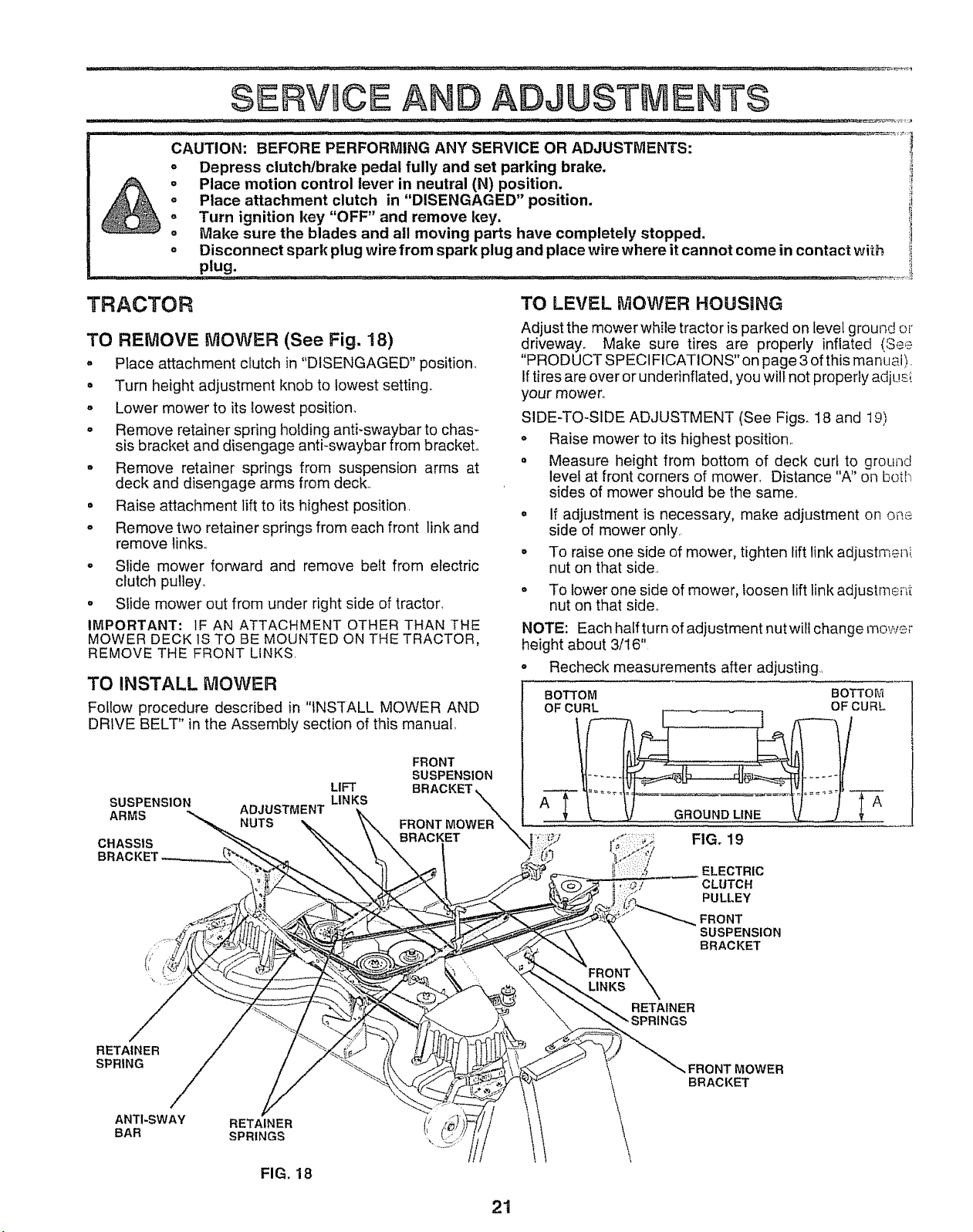
TO REMOVE MOWER (See Fig. 18)
° Place attachment clutch in "DISENGAGED" position.,
= Turn height adjustment knob to lowest setting.
° Lower mower to its lowest position.
o Remove retainer spring holding anti-swaybar to chas-
sis bracket and disengage anti-swaybar from bracket.,
= decRkemOVaendretainedirsengag earmSsprings l_Im dSUcSpensionarms at
• Raise attachment lift to its highest position.
. Remove two retainer springs from each front link and
remove links.,
o Slide mower forward and remove belt from electric
clutch puley.
° Slide mower out from under right side of tractor,,
IMPORTANT: IF AN ATTACHMENT OTHER THAN THE
MOWER DECK 1STO BE MOUNTED ON THE TRACTOR,
REMOVE THE FRONT LINKS.
TO INSTALL MOWER
Follow procedure described in "INSTALL MOWER AND
TO LEVEL MOWER HOUSING
Adjust the mower while tractor is parked on level g round or
driveway. Make sure tires are properly inflated {See
"PRODUCT SPECIFICATIONS"on page 3 of this manual).
If tires are over or underinflated, you will not properly adjust
your mower.,
SIDE-TO-SIDE ADJUSTMENT (See Figs. 18 and t9)
o Raise mower to its highest position.
• Measure height from bottom of deck curt to ground
level at front corners of mower, Distance "A" on botl-_
sides of mower should be the same.
= If adjustment is necessary, make adjustment on one
side of mower only.,
o To raise one side of mower, tighten lift link adjustmeni
nut on that side,
To lower one side of mower, loosen lift link adjustment
nut on that side,
NOTE: Each half turn of adjustment nutwill change mower
height about 3/16"
• Recheck measurements after adjusting_
BOTTOM BOTTOM
OF CURL OF CURL
21
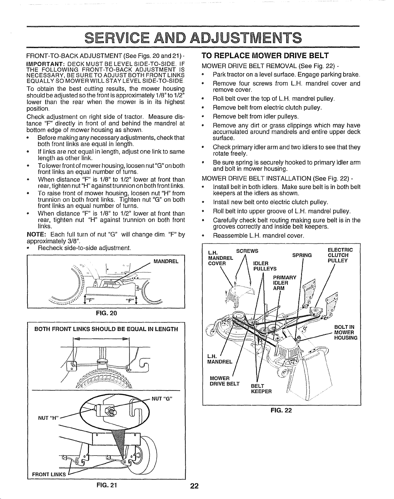
FRONT-TO-BACK ADJUSTMENT (See Figs. 20 and 21) -
IMPORTANT: DECK MUST BE LEVEL SIDE-TO-SIDE. IF
THE FOLLOWING FRONT-TO-BACK ADJUSTMENT IS
NECESSARY, BE SURE TO ADJUST BOTH FRONT LINKS
EQUALLY SO MOWER WILL STAY LEVEL SIDE-TO-SIDE
To obtain the best cutting results, the mower housing
should be adjusted so the front is approximately 1/8" to 1/2"
lower than the rear when the mower is in its highest
position.
Check adjustment on right side of tractor. Measure dis-
tance "F' directly in front of and behind the mandrel at
bottom edge of mower housing as shown
o Before making any necessary adjustments, check that
both front links are equal in length.
° If links are not equal in length, adjust one link to same
length as other link.
° To lower front of mower housing, loosen nut"G"on both
front links an equal number of turns
• When distance "F" is 1/8" to 1/2" lower at front than
{ear, tighten nut "H" against tru nnion on both front links.
• To raise front of mower housing, loosen nut "H" from
trunnion on both front links° Tighten nut "G" on both
front links an equal number of turns.
, When distance "F" is 1/8" to 1/2" lower at front than
rear, tighten nut "H" against trunnion on both front
links.
NOTE: Each full turn of nut "G" will change dim "F" by
approximately 3/8"
o Recheck side-to-side adjustment_
_ MANDREL
FIG, 20
BOTH FRONT LINKS SHOULD BE EQUAL IN LENGTH
NUT"H
FRONT LINKS
MOWER DRIVE BELT REMOVAL (See Fig° 22) -
= Park tractor on a level surface. Engage parking brake.
• Remove four screws from LH mandrel cover and
remove cover°
° Roil belt over the top of L_Homandrel pulley.
= Remove belt from electric clutch pulley.
° Remove belt from idler pulleys_
° Remove any dirt or grass clippings which may have
accumulated around mandrels and entire upper deck
surface_
° Check primary idler arm and two idlers to see that they
rotate freely.
° Be sure spring is securely hooked to primary idler arm
and bolt in mower' housing.
MOWER DRIVE BELT INSTALLATION (See Fig. 22) -
- Install belt in both idlers. Make sure belt is in both belt
keepers at the idlers as shown.
- Install new belt onto electric clutch pulley°
° Roll belt into upper groove of L.H_ mandrel pulley.
= Carefully check belt routing making sure belt is in the
grooves correctly and inside belt keepers.
° Reassemble L_H. rnand{el cover..
LH. SCREWS ELECTRIC
MANDREL SPRING CLUTCH
COVER IDLER PULLEY
PULLEYS
PRIMARY
IDLER
ARM
BOLT IN
MOWER
HOUSING
MANDREL
MOWER
DRIVE BELT
BELT
KEEPER
FIG. 22
FIG. 21 22
SERVnOE AND
o
o
8
o
o
o
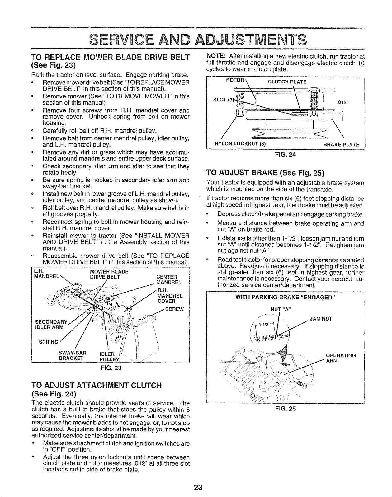
TO REPLACE MOWER BLADE DRIVE BELT
(See Fig, 23)
Park the tractor on level surface.. Engage parking brake_
= Remove mower drive belt (See"TO REPLACE MOWER
DRIVE BELT" ill this section of this manual).
o Remove mower (See "TO REMOVE MOWER" in this
section of this manual).
, Remove four screws from R.H.. mandrel cover and
remove cover.. Unhook spring from bolt on mower
housing..
Carefully roll belt off RH.. mandrel pulley.
Remove belt from center mandrel pulley, idler pulley,
and LH. mandrel pulley.,
Remove any dirt or grass which may have accumu-
lated around mandrels and entire upper deck surface..
Check secondary idler arm and idler to see that they
rotate freely..
Be sure spring is hooked in secondary idler arm and
sway-bar bracket,.
Install new bert in lower groove of LH, mandrel pulley,
idler pulley, and center mandrel pulley as showm
Roll belt over RH. mandrel pulley. Make sure belt is in
ADJUSTMENTS
NOTE: After installing a new electric clutch, run tractor at
full throttle and engage and disengage electric clutch I0
cycles to wear in clutch plate.
ROTO_ :::::::::,,CLUTCH PLATE ..............
SLOT (3) _ .... ........ : ,012 ,,
NYLON LOCKNUT (3) BRAKE PLATE
FIG, 24
TO ADJUST BRAKE (See Fig. 25)
Your tractor is equipped with an adjustable brake system
which is mounted on the side of the transaxle..
If tractor requires more than six (6) feet stopping distance
at high speed in highest gear, then brake must be adjusted.
al! grooves property..
Reconnect spring to bolt in mower housing and reim
stall R.H,. mandrel cover_
Reinstall mower to tractor (See "INSTALL MOWER
AND DRWE BELT" in the Assembly section of this
manual).,
Reassembfe mower drive belt (See '%O REPLACE
MOWER DRIVE BELT" in this section of this manual)..
MOWER BLADE
DRIVE BELT CENTER
MANDREL
MANDREL
COVER
SECONDARY
IDLER ARM
SPRING
SWAY-BAR
BRACKET
IDLER
PULLEY
FIG. 23
\
\
\
TO ADJUST ATTACHMENT CLUTCH
(See Fig. 24)
The electric clutch should provide years of service,, The
clutch has a built-in brake that stops the pulley witMn 5
seconds,, Eventually, tfte internal brake will wear which
may cause the mower blades to not engage, or, to not stop
as require& Adjustments should be made by your nearest
authorized service center/department,.
', Make sure attachment clutch and ignition switches are
in "OFF" position..
° Adjust the tllree nylon locknuts until space between
clutch plate and rotor measures .012" at all three slot
locations cut in side of brake plate..
• Depress clutch/brake pedal and engage parking brake.
• Measure distance between brake operating arm and
nut "A" on brake rod..
If distance is other than 1-1/2", loosen jam nut and turn
nut "A" until distance becomes 1-1/2", Retighten jam
nut against nut "A",,
Road test tractor for proper stopping distance as stated
above,, Readjust if necessary, if stopping distance is
still greater than six (6) feet in highest gear, furtiter
maintenance is necessary,, Contact your nearest aLI-
thorized service center!department,,
WITH PARKING BRAKE"ENGAGED"
NUT "A"
JAM NUT
FIG, 25
23
SERVtICE AND ADJUSTMENTS
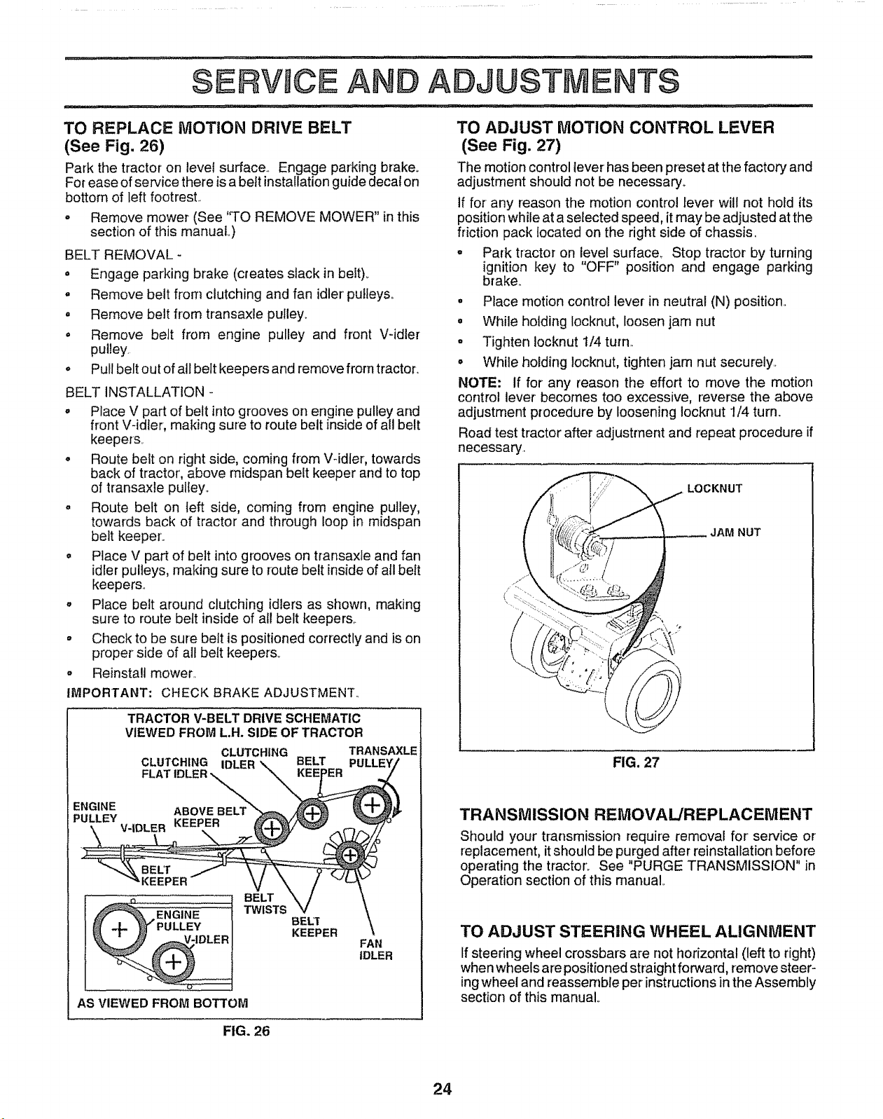
TO REPLACE MOTION DRIVE BELT
(See Fig. 26)
Park the tractor on level surface.. Engage parking brake°
For ease of service there is a belt installation guide decal on
bottom of left footrest..
o Remove mower (See 'q-O REMOVE MOWER" in this
section of this manual°)
BELT REMOVAL -
• Engage parking brake (creates slack in belt)..
= Remove belt from clutching and fan idler pulleys..
= Remove belt from transaxle pulley_
° Remove belt from engine pulley and front V-idler
pulley.
o Pull belt out of all belt keepers and remove from tractor.
BELT INSTALLATION -
= Place V part of belt into grooves on engine pulley and
front V-idler, making sure to route belt inside of all belt
keepers..
• Route belt on right side, coming from V-idler, towards
back of tractor', above midspan belt keeper and to top
of transaxle pulley..
= Route belt on left side, coming from engine pulley,
towards back of tractor and through loop in midspan
belt keeper..
o Place V part of belt into grooves on transaxle and fan
idler pulleys, making sure to route belt inside of all belt
keepers..
o Place belt around clutching idlers as shown, making
sure to route belt inside of all belt keepers,.
o Check to be sure belt is positioned correctly and is on
proper side of all belt keepers_
Reinstall mower..
°
IMPORTANT: CHECK BRAKE ADJUSTMENT.,
TRACTOR V-BELT DRIVE SCHEMATIC
VIEWED FROM L.H. SIDE OF TRACTOR
CLUTCHING TRANSAXLE
CLUTCHING IDLER BELT
FLAT IDLER _ER
ENGINE ABOVE BELT
PULLEY
V-IDLER KEEPER
BELT
TWISTS
BEL"f
KEEPER
FAN
IDLER
AS VIEWED FROM BOTTOM
TO ADJUST MOTION CONTROL LEVER
(See Fig. 27)
The motion control iever has been preset at the factory and
adjustment should not be necessary.
if for any reason the motion control lever will not hold its
position while at a selected speed, it may be adjusted at the
friction pack located on the right side of chassis.
° Park tractor on level surface_ Stop tractor by turning
ignition key to "OFF" position and engage parking
brake.
° Place motion control lever in neutral (N) position..
o While holding Iocknut, loosen jam nut
, Tighten Iocknut 1/4 turn..
o While holding locknut, tighten jam nut securely..
NOTE: If for any reason the effort to move the motion
control lever becomes too excessive, reverse the above
adjustment procedure by loosening locknut 1/4 turn.
Road test tractor after adjustment and repeat procedure if
necessary.
LOCKNUT
JAM NUT
FIG. 27
TRANSMISSION REMOVAL/REPLACEMENT
Should your transmission require removal for service or
replacement, it should be purged after reinstallation before
operating the tractor. See "PURGE TRANSMISSION" in
Operation section of this manual
TO ADJUST STEERING WHEEL ALIGNMENT
If steering wheel crossbars are not horizontal (left to right)
when wheels are positioned straight forward, remove steer-
ing wheel and reassemble per instructions in the Assembly
section of this manual
FIG. 26
24
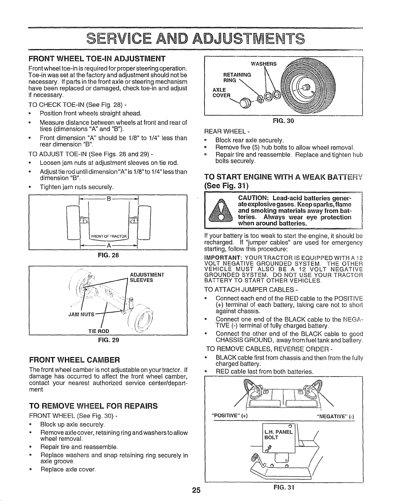
FRONT WHEEL TOE-IN ADJUSTMENT
Front wheel toe-in is required for proper steering operation,,
Toe-in was set at the factory and adjustment should not be
necessary,, if parts inthe front axle or steering mechanism
have been replaced or damaged, check toe-in and adjust
if necessary.,
TO CHECK TOE-IN (See Fig° 28) -
o Position front wheels straight ahead,,
o Measure distance between wheels at front and rear of
tires (dimensions "A" and "B").,
- Front dimension "A" should be 1/8" to 1/4" less than
rear dimension "B".,
TO ADJUST TOE-IN (See Figs. 28 and 29) -
. Loosen jam nuts at adjustment sleeves on tie rod_
: Adjusttieroduntitdimension"A"isl/8"tol/4"lessthan
dimension "B".,
° Tighten jam nuts securely.
WAS!
RETAINING
RING
AXLE
COVER
FIG. 30
REAR WHEEL -
° Block rear axle securely.
o Remove five (5) hub bolts to allow wheel removal,,
- Repair tire and reassemble, Replace and tighten hub
bolts securely_
TO START ENGINE WiTH A WEAK IBATTEFiY
(See Fig. 31)
__B
,,_A _
FIG. 28
, ADJUSTMENT
i SLEEVES
JAM
TIE ROD
FIG. 29
FRONT WHEEL CAMBER
The front wheel camber is not adjustable on your tractor,, If
damage has occurred to affect the front wheef camber,
contact your nearest authorized service centeddepart-
ment
TO REMOVE WHEEL FOR REPAIRS
FRONT WHEEL (See Fig., 30) -
o Block up axfe securely..
o Remove axle cover, retaining ring and washers to allow
wheel removal
• Repair tire and reassemble.,
° Replace washers and snap retaining ring securely in
axle groove.
. Replace axle cover,
If your battery is too weak to start the engine, it should be
recharged, if "jumper cables" are used for emergency
starting, follow this procedure:
IMPORTANT: YOUR TRACTOR IS EQUIPPED WITH A 12
VOLT NEGATIVE GROUNDED SYSTEM, THE OTHER
VEHICLE MUST ALSO BE A 12 VOLT NEGATIVE
GROUNDED SYSTEM. DO NOT USE YOUR TRACTOR
BATTERY TO START OTHER VEHICLES,,
TO ATTACH JUMPER CABLES -
o Connect each end of the RED cable to the POSITIVE
(+) terminal of each battery, taking care not to short
against chassis.
• Connect one end of the BLACK cable to the NEGA-
TIVE (-) terminal of fully charged battery,
• Connect the other end of the BLACK cable to good
CHASSIS GROUND, away from fuel tank and battery,
TO REMOVE CABLES, REVERSE ORDER -
° BLACK cable first from chassis and then from the fully
charged battery.
. RED cable last from both batteries°
"POSITIVE" (+)
"NEGATIVE" {-)
BOLT
r_
25 FIG, 31
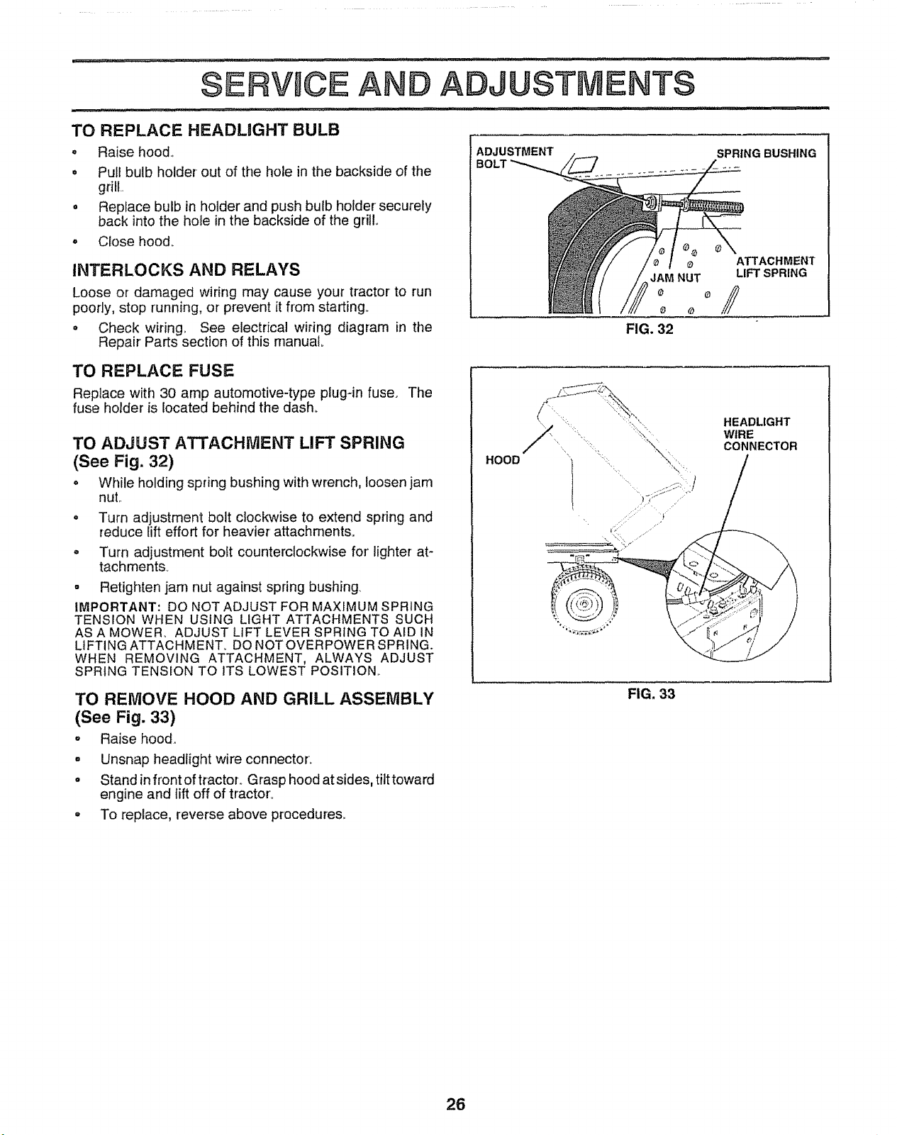
$ERV CE A D ADJUSTMENTS
..... i, / J illl,,
TO REPLACE HEADUGHT BULB
° Raise hood.,
. Pull bulb holder- out of the hole in the backside of the
grill..
° Replace bulb in holder and push bulb holder securely
back into the hole in the backside of the grill,
o Close hood_
INTERLOCKS AND RELAYS
Loose or damaged wiring may cause your tractor to run
poorly, stop running, or prevent it from starting..
° Check wiring. See electrical wiring diagram in the
Repair' Parts section of this manual.
ADJUSTMENT
SPRING BUSHING
o ATTACHMENT
JAM NUT LIFT SPRING
FIG. 32
TO REPLACE FUSE
Replace with 30 amp automotive-type plug-in fuse. The
fuse holder is located behind the dash°
TO ADJUST ATTACHMENT LIFT SPRING
(See Fig. 32)
o While holding spring bushing with wrench, loosen jam
nut..
Turn adjustment bolt clockwise to extend spring and
reduce lift effort for heavier' attachments°
Turn adjustment bolt counterclockwise for' lighter at-
tachments_
- Retighten jam nut against spring bushing,
IMPORTANT: DO NOT ADJUST FOR MAXIMUM SPRING
TENSION WHEN USING LIGHT ATTACHMENTS SUCH
AS A MOWER,, ADJUST LIFT LEVER SPRING TO AID IN
LIFTING ATTACHMENT_ DO NOT OVERPOWER SPRING.
WHEN REMOVING ATTACHMENT, ALWAYS ADJUST
SPRING TENSION TO ITS LOWEST POSITION,•
TO REMOVE HOOD AND GRILL ASSEMBLY
(See Fig. 33)
o Raise hood,
. Unsnap headlight wire connector.
= Stand in front of tractoL Grasp hood at sides, tilttoward
engine and lift off of tractor°
° To replace, reverse above procedures°
HOOD
HEADLIGHT
WIRE
CONNECTOR
FIG. 33
26
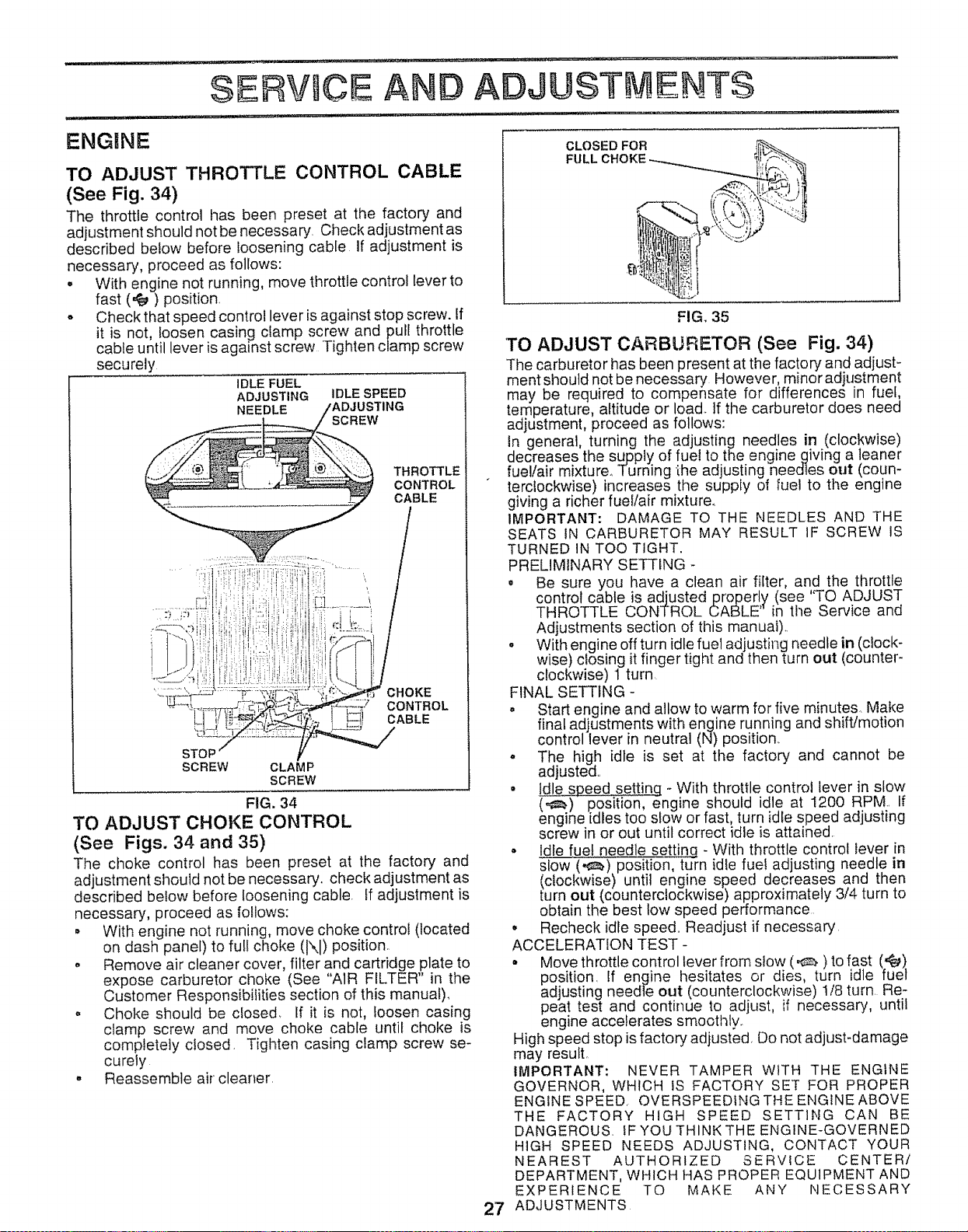
SERVUCE A
ADJUSTMENTS
ENGINE
TO ADJUST THROTTLE CONTROL CABLE
(See Fig. 34)
The throttle control has been preset at the factory and
adjustment should not be necessary. Check adjustment as
described below before loosening cable If adjustment is
necessary, proceed as follows:
• With engine not running, move throttle control lever to
fast (,€_) position,
o Check that speed control lever is against stop screw. If
it is not, loosen casing clamp screw and pull throttle
cable until lever is against screw Tighten clamp screw
securely
IDLE FUEL
ADJUSTING IDLE SPEED
NEEDLE
THROTTLE
CONTROL
CABLE
CHOKE
CONTROL
CABLE
STOP
SCREW CLAMP
SCREW
FIG. 34
TO ADJUST CHOKE CONTROL
(See Figs. 34 and 35)
The choke control has been preset at the factory and
adjustment should not be necessary, check adjustment as
described below before loosening cable. If adjustment is
necessary, proceed as follows:
• With engine not running, move choke control (located
on dash panel) to full choke (IXI) position..
• Remove air cleaner cover, filter and cartridge plate to
expose carburetor choke (See "AIR FILTER" in the
Customer Responsibilities section of this manual).
o Choke should be closed. If it is not, loosen casing
clamp screw and move choke cable until choke is
completely closed, Tighten casing clamp screw se-
curely
° Reassemble air cleaner,
CLOSED FOR
FULL
FIG. 35
TO ADJUST CARBURETOR (See Fig. 34)
The carburetor has been present at the factory and adjust-
ment should not be necessary However, minoradjustment
may be required to compensate for differences in fuel,
temperature, altitude or load. tf the carburetor does need
adjustment, proceed as follows:
In general, turning the adjusting needles in (clockwise)
decreases the supply of fue! to the enginegiving a leaner
fuel!air mixture_ Turning the adjusting needles out (coun-
terclockwise) increases ttne supply of fuel to the engine
giving a richer fuel/air mixture,
IMPORTANT: DAMAGE TO THE NEEDLES AND THE
SEATS IN CARBURETOR MAY RESULT tF SCREW IS
TURNED IN TOO TIGHT.
PRELIMINARY SETTING -
. Be sure you have a clean air filter, and the throttle
control cable is adjusted properly (see "TO ADJUST
THROTTLE CONTROL CABLE" in the Service and
Adjustments section of this manual)_,
• With engine off turn idle fuel adjusting needle in (clock-
wise) closing it finger tight and then turn out (counter-
clockwise) 1 turn.
FINAL SETTING -
• Start engine and allow to warm for five minutes. Make
final adjustments with engine running and shift/motion
control lever in neutral (N) position,
o The high idle is set at the factory and cannot be
adjusted,,
• Idle speed setting _With throttle control lever in stow
(,_.) position, engine should idle at 1200 RPM., If
engine idles too slow or fast, turn idle speed adjusting
screw in or out until correct idle is attained.
• Idle fue! needle setting - With throttle control lever in
s-qow(_) position, turn idle fuel adjusting needle in
(clockwise) until engine speed decreases and then
turn out (counterclockwise) approximately 3/4 turn to
obtain the best low speed performance
• Recheck idle speed.. Readjust if necessary
ACCELERATION TEST -
• Move throttle control lever from slow (_ ) to fast ('_e_)
position. If engine hesitates or dies, turn idle fuel
adjusting needle out (counterclockwise) 1/8 turn Re-
peat test and continue to adjust, if necessary, until
engine accelerates smoothly_
High speed stop is factory adjusted, Do not adjust-damage
may result.
IMPORTANT: NEVER TAMPER WITH THE ENGINE
GOVERNOR, WHICH IS FACTORY SET FOR PROPER
ENGINE SPEED. OVERSPEEDING THE ENGINE ABOVE
THE FACTORY HIGH SPEED SETTING CAN BE
DANGEROUS. IF YOU THINKTHE ENGINE-GOVERNED
HiGH SPEED NEEDS ADJUSTING, CONTACT YOUR
NEAREST AUTHORIZED SERVICE CENTER/
DEPARTMENT, WHICH HAS PROPER EQUIPMENT AND
EXPERIENCE TO MAKE ANY NECESSARY
ADJUSTMENTS
27
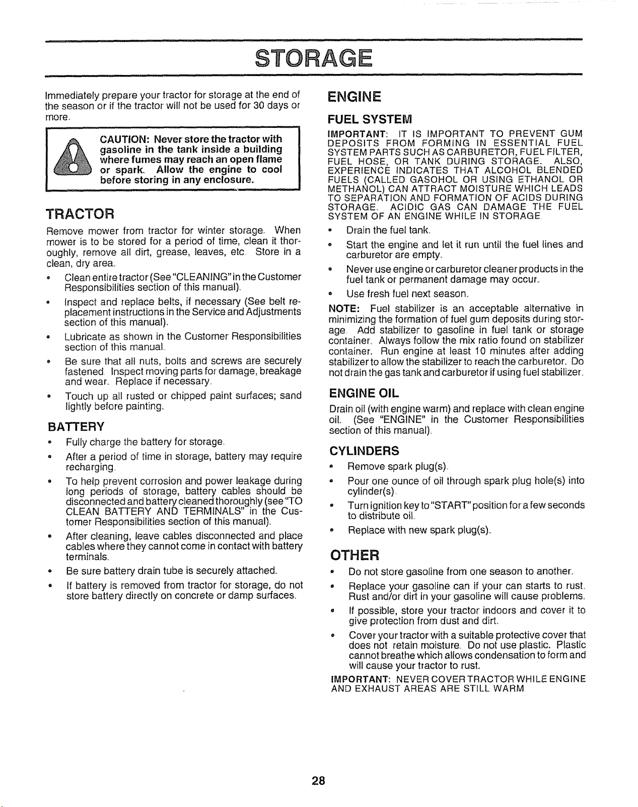
Immediately prepare your tractor for storage at the end of
the season or if the tractor will not be used for 30 days or
more.
,! .................... : ............ ......... :::::::
J CAUTION: Never store the tractor with
gasoline in the tank inside a building |
where fumes may reach an open flame J
or spark. Allow the engine to cool I
..............befo!e storing! n any enclosure. !
i
TRACTOR
Remove mower from tractor for winter storage. When
mower is to be stored for a period of time, clean it thor-
oughly, remove all dirt, grease, leaves, etc. Store in a
clean, dry area..
• Clean entire tractor (See "CLEANING" in the Customer
Responsibilities section of this manual).
° Inspect and replace belts, if necessary (See belt re,-
placement instructions in the Service and Adjustments
section of this manual)°
• Lubricate as shown in the Customer Responsibilities
section of this manual.
° Be sure that all nuts, bolts and screws are securely
fastened inspect moving parts for damage, breakage
and wear.. Replace if necessary.
° Touch up alt rusted or chipped paint surfaces; sand
lightly before painting°
BATTERY
° Fully charge the battery for storage.
o After a period of time in storage, battery may require
recharging,
° To help prevent corrosion and power leakage during
tong periods of storage, battery cables should be
disconnected and battery cleaned thoroughly (see "TO
CLEAN BATTERY AND TERMINALS" in the Cus-
tomer Responsibilities section of this manual).
° After cleaning, leave cables disconnected and place
cables where they cannot come in contact with battery
terminals,
o Be sure battery drain tube is securely attached.
° tf battery is removed from tractor for storage, do not
store battery directly on concrete or damp surfaces.
ENGINE
FUEL SYSTEM
IMPORTANT: IT IS IMPORTANT TO PREVENT GUM
DEPOSITS FROM FORMING IN ESSENTIAL FUEL
SYSTEM PARTS SUCH AS CARBURETOR, FUEL FfLTER,
FUEL HOSE, OR TANK DURING STORAGE. ALSO,
EXPERIENCE INDICATES THAT ALCOHOL BLENDED
FUELS (CALLED GASOHOL OR USING ETHANOL OR
METHANOL) CAN ATTRACT MOISTURE WHICH LEADS
TO SEPARATION AND FORMATION OF ACIDS DURING
STORAGE, ACIDIC GAS CAN DAMAGE THE FUEL
SYSTEM OF AN ENGINE WHILE IN STORAGE
o
o
Drain the fuel tank,
Start the engine and let it run until the fuel lines and
carburetor are empty_
Never use engine or carburetor cleaner products in the
fuel tank or-permanent damage may occur..
Use fresh fuel next season..
NOTE: Fuel stabilizer is an acceptable alternative in
minimizing the formation of fuel gum deposits during stor-
age Add stabilizer to gasoline in fuel tank or storage
container, Always follow the mix ratio found on stabilizer'
container. Run engine at least I0 minutes after' adding
stabilizer to allow the stabilizer to reach the carburetor. Do
not drain the gas tank and carburetor if using fuel stabilizer.
ENGINE OIL
Drain oil (with engine warm) and replace with clean engine
oil.. (See "ENGINE" in the Customer' Responsibilities
section of this manual).
CYLINDERS
° Remove spark plug(s)
° Pour' one ounce of oil through spark plug hole(s) into
cylinder(s),
° Turn ignition key to"START" position for a few seconds
to distribute oi!,
° Replace with new spark plug(s),.
OTHER
° Do not store gasoline from one season to another..
• Replace your gasoline can if your can starts to rust.
Rust and/or dirt in your gasoline will cause problems.
, If possible, store your tractor' indoors and cover it to
give protection from dust and dirt..
° Cover your tractor with a suitable protective cover that
does not retain moisture.. Do not use plastic. Plastic
cannot breathe which allows condensation to form and
wilt cause your tractor to rust.
IMPORTANT: NEVER COVER TRACTOR WHILE ENGINE
AND EXHAUST AREAS ARE STILL WARM
28

TROLl LESHOOTING POll,ITS
PROBLEM
Will not start
Hard to start
CAUSE
t. Out of fuel
2 Engine not "CHOKED" properly.
3 Engine flooded
4 Bad spark plug
5 Dirty air filter
6, Dirty fuel filter.
7, Water in fuel
8 Loose or damaged wiring
9 Carburetor out of adjustment..
10, Engine valves out of adjustment..
I.. Dirty air filter
2, Bad spark plug
3 Weak ordead battery
4 Dirty fuel filter
5 Stale ordirty fuel,
6 Loose or damaged widng
7., Carburetor out of adjustment
8. Engine valves out of adjustment
CORRECTION
1 Fill fuel tank
2, See "TO START ENGINE" in Operation section
3 Wait several minutes before attempting to start
4 Replace spark plug
5. Clean/replace air filter
6, Replace fue! filter
7.. Drain fuel tank and carburetor, refi[I tank with fresh
gasoline and replace fuel filter
8 Check allwiring
9 Contact an authorized service centeddepartment
10. Contact an authorized service center/depadmenI.
1,, Clean/replace air filter
2., Replace sparkplug
3 Recharge or replace battery
4, Replace fuel lilter,.
5 Drain fuel tank and refill with fresh gasoline
6 Check all wiring
7 Contact an authorized service center/department,
8 Contact an authorized service center/depadment,
iu_l,,l,l,,_,,,J
Engine will not turn over
1 Clutch/brake pedal not depressed
2 Attachment clutch is engaged
3, Weak or dead battery
4. Blown fuse
5 Corroded batter] terminals.
6 Loose or damaged wiring
7 Faulty ignition switch,
8 Faulty solenoid or starter
9, Faulty operator presence switch(es),
Engine clicks but will not
start
Loss of power
Excessive vibration
1 Weakordead battery
2 Corroded battery terminals
3 Loose or damaged wiring,
4.. FauItysolenoid or starter.
1 Cutting too much grass/too fast.
2, Throttle in "CHOKE" position.
3, Build-up of grass, leaves and trash under mower.
4. Dirty air filter
5 Low oil level/dirty oil
6 Faulty spark plug
7 Dirty fuel fitter
8. Stale or dirty fuel,
9. Water in fuel
I0, Spark plug wireloose,
1t. Dirty engine air screen/fins
12 Dirty/clogged muffler
13 Loose or damaged wiring,
I4. Carburetor out of adjustment
15,, Engine valves out of adjustment
1 Worn, bent or loose blade.
2 Bent blade mandrel
3, Loose/damaged part(s)
t.. Depress clutch/brake pedal
2, Disengage attachment clutch
3, Recharge or replace battery,,
4 Replace fuse
5 Clean battery terminals,
6, Check all wiring..
7 Checidreplace ignition switch,
8. Checldreplace solenoid or starter.
9, Contact an authorized service center/deparlment
1 Rechargeor replace battery,,
2, Clean battery terminals
3. Check all wiring
4 Chec_'Jreplace solenoid or starter
t, Set in "Higher Cut" position!reduce speed,
2. Adjustthrottie control
3 Clean underside of mower housing,
4 Clean/replace air filter
5 Check oil level/change oil
6 Clean and regap or change spark plug
7, Replace fuel filter
8., Drain fueltank and relill with fresh gasoline.
9 Drain fuel tank and carburetor, refill tank with fresh
gasoline and replace fuel filter
t0 Connect and tighten spark plug wire
11 Clean engine air screen!fins,
12, Clean/replace muffler
t3., Check all wiring
t4, Contact an authorized service center/department
15 Contact an authorized service centerldepartmenl
1 Replace blade Tighten blade bolt,
2 Replace blade mandrel
3 Tighten Ioose part(s) Replace damaged pads
29

OOTJNG POaNT$
PROBLEM
Engine continues to run
when operator leaves seat
with attachment clutch
engaged
Poorcut-uneven
Mower blades will not
rotate
Poor grass discharge
Headlight(s) not working
(if so equipped)
Battery wilt not charge
Loss of drive
Engine "backfires"
when turning engine
"OFF"
CAUSE
1 Faulty operator-safety presence control system
1 Worn, bent or loose blade
2 Mower deck not level.
3, Buildup of grass, leaves, and trash under mower
4 Bent blade mandrel
5 Clogged mower deck vent holes from buildup of
grass, leaves, and trash around mandrels
2
Obstruction in clutch mechanism
Worn/damaged mower drive belt.
3 Frozen idler puliey.
4 Frozen blade mandret
t Engine speed too slow
2 Travel speed too fast.
3 Wet grass..
4 Mower deck not level
5 Low/uneven tire air pressure
6. Worn, bent or loose btade
7. Buildup of grass, _eaves and trash under mower
8. Mower drive belt worn
9. Blades improperly installed
10. Improper blades used.
11 Clogged mower deck vent ho_es from buildup of
grass, leaves, and trash around mandrels.
1 Switch is "OFF
2 Bulb(s) burnedout
3. Faufty light switch.
4.. Loose or damaged wiring.
5, Blown fuse..
1 Bad battery cell(s)..
2 Poor cable connections..
3 Faulty regulator (if so equipped)
4 Faulty alternator.
1, Freewheel control in "disengaged" position
2. Motion drive belt worn, damaged or broken.
3, Air trapped in transmission during shpment
or servicing,
t, Engine throttle control not set at "SLOW"
position for 30 seconds before stopping engine
CORRECTION
,, ,=,=l,i=,=lll=,lllL =
Check wiring, switches and connections If not
corrected, contact an authorized service center/
department
,/,J,,, ,, ,ll i ill ,
1. Replace blade.. Tighten blade bolt,.
2. Level mower deck
3, Clean underside of mower housing
4. Replace bfade mandrel
5.. Clean around mandrels to open vent ho_es.
1 Remove obstruction
2 Replace mower dr_ve belt.
3 Replace idler pulley,.
4 Replace blade mandrel.
t Place throttle control in "FAST" position.,
2 Shift to slower speed,
3 Allow grass to dry before mowing.,
4 Levet mower deck
5 Check tires for proper air pressure,
6 Replace/sharpen blade Tighten blade bolt..
7 Clean underside of mower housing
8 Replace mower drive belt
9 Reinstall blades sharp edge down.
10 Replace with blades listed in this manuaE
tl Clean around mandrels to open vent holes.
1., Turn switch "ON",.
2. Replace bulb(s)
3., Check/replace tight switch
4,. Check wiring and connections,.
5 Replace fuse..
1 Replace battery.
2. Check/clean alFconnections.
3 Replace regulator.
4. Replace alternator
t Ptace freewheel control in "engaged" position.
2 Replace motion drive belt..
3. Purge transmission
1,_ Move throttle control to "SLOW" position and atlow
to idle for 30 seconds before stopping engine
3O
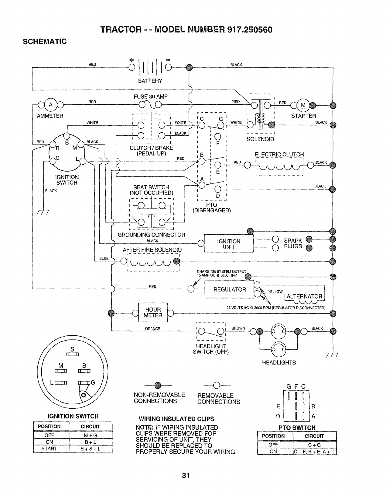
SCHEMATIC
TRACTOR - - MODEL NUMBER 917.250560
RED
,p
0
BATTERY
BLACK
AMMETER
RED
WHITE
S BLACK
L(
IGNITION
SWITCH
BLACK
FUSE30 AMP.
I 0 ' 0 I WHITE
1 I I
i
[ J
CLUTCHI BRAKE
(PEDALUP)
RED
SEATSWITCH
(NOTOCCUPIED)
L -I
GROUNDINGCONNECTOR
BLACK
AFTER FIRE SOLENOID
f 1
HOUR
METER
ORANGE
RED
E
I
A
I
!
L ..... J
PTO
(DISENGAGED)
ELECTRICCLUTCH
t I
L J
SLACK
t IGNITION
UNIT
O.A_O,.GSYSTEMOUTP,_
_J_ REGULATOR _ YELLOW 1
2B VOLTS AC @ 3600 RPM (REGULATOR DISCONNECTED}
t I
HEADLIGHT
SWITCH(OFF) F
HEADLIGHTS
-7
IGNITION SWITCH
I POSITION CIRCUIT
OFF M+ G
ON B+ L
t START B + S + L
®
NON-REMOVABLE
CONNECTIONS
O
REMOVABLE
CONNECTIONS
WIRING INSULATED CLIPS
NOTE: IF WIRING INSULATED
CLIPS WERE REMOVED FOR
SERVICING OF UNIT, THEY
SHOULD BE REPLACED TO
PROPERLY SECURE YOUR WIRING
GFC
nDO
E I_B
D H_A
PTO SWITCH
I POSITION 1 CIRCUIT [
OFF C + G
ON C+F,B+E,A+D]
31
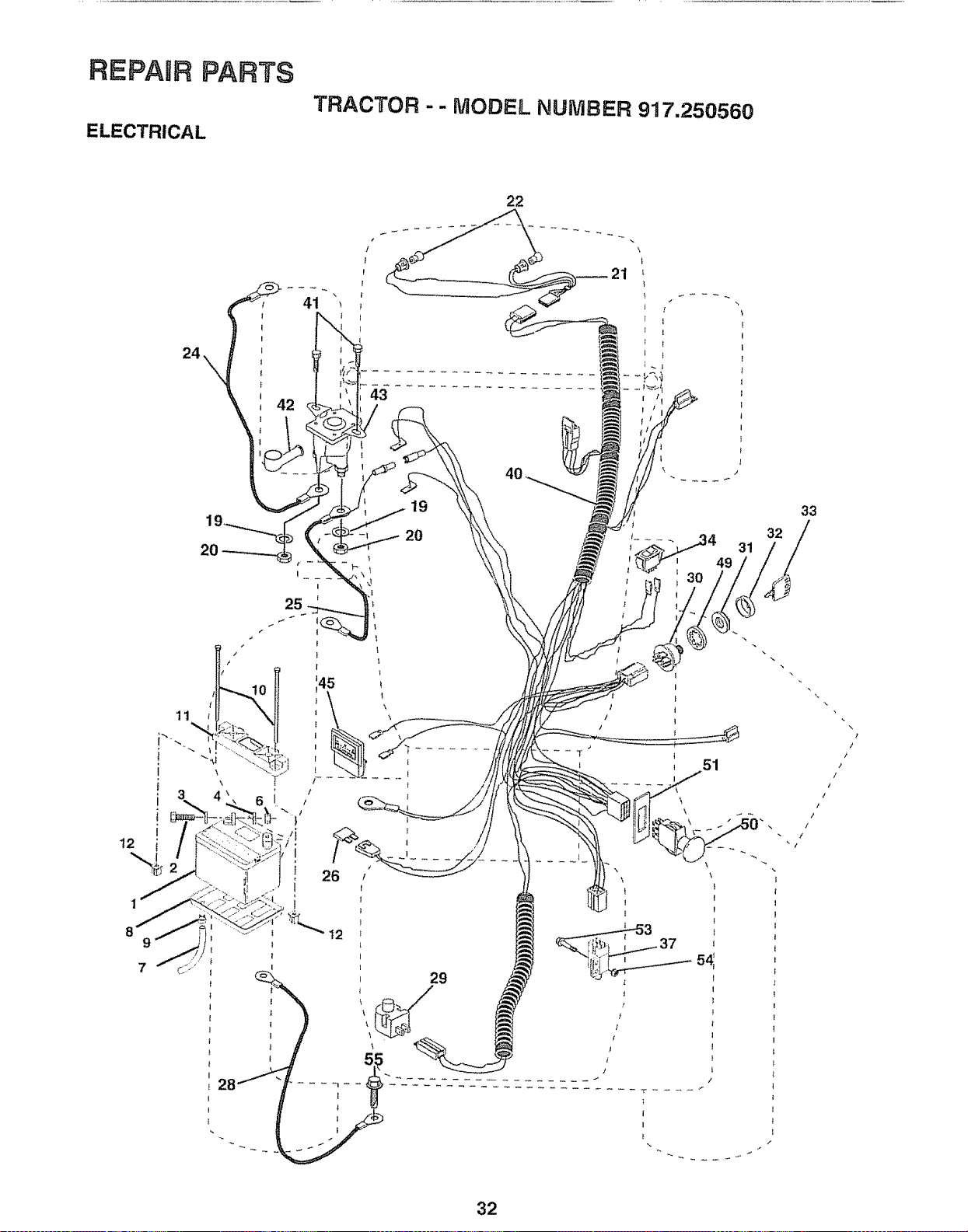
REPAIR PARTS
ELECTRICAL
TRACTOR -- MODEL NUMBER 917.250560
20
9
7
t
19
20
32
31
51
\
f
I
33
32
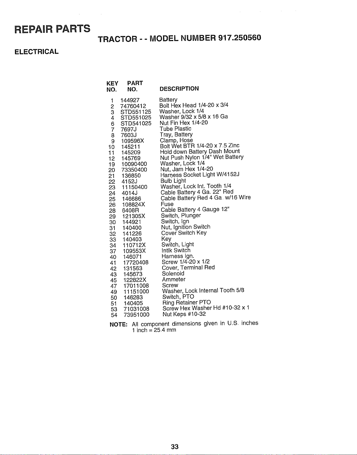
REPAnR PARTS
ELECTRICAL
TRACTOR - - MODEL NUMBER 917.250560
KEY PART
NOo NO. DESCRIPTION
1 144927 Battery
2 74760412 Bolt Hex Head 1/4-20 x 3/4
3 STD551125 Washer, Lock 1/4
4 STD551025 Washer 9/32 x 5/8 x 16 Ga
6 STD541025 Nut Fin Hex 1/4-20
7 7697J Tube Plastic
8 7603J Tray, Battery
9 109596X Clamp, Hose
10 145211 Bolt Wet BTR 1/4-20 x 75 Zinc
11 145209 Hotd down Battery Dash Mount
12 145769 Nut Push Nylon 1/4" Wet Battery
19 10090400 Washer, Lock 1/4
20 73350400 Nut, Jam Hex 1/4_20
2'1 136850 Har0ess Socket Light W/4152J
22 4152J Bulb Light
23 11150400 Washer, Lock Int. Tooth 1/4
24 4014J Cable Battery 4 Gao22" Red
25 146686 Cable Battery Red 4 Ga. w/16 Wire
26 108824X Fuse
28 6408R Cable Battery 4 Gauge 12"
29 121305X Switch, Plunger
30 144921 Switch, Ign
31 140400 Nut, Ignition Switch
32 14'1226 Cover Switch Key
33 140403 Key
34 110712X Switch, Light
37 109553X lntfk Switch
40 146071 Harness lgn.
41 17720408 Screw 1/4-20 x 1/2
42 131563 Cover, Terminal Red
43 145673 Solenoid
45 122822X Ammeter
47 17011008 Screw
49 t 1151000 Washer, Lock Internal Tooth 5/8
50 146283 Switch, PTO
51 140405 Ring Retainer PTO
53 71031008 Screw Hex Washer Hd #10-32 x 1
54 73951000 Nut Keps #10-32
NOTE:
Al! component dimensions given in U_S. inches
1 inch = 25.4 mm
33
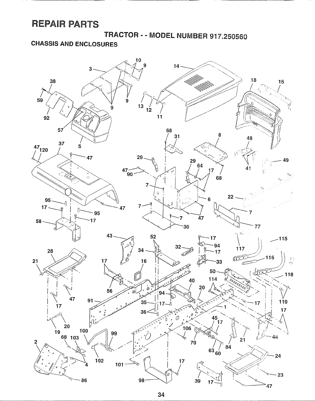
REPAnR PARTS
TRACTOR -- MODEL NUMBER 917.250560
CHASSIS AND ENCLOSURES
10
9
59
92
9
13
11
18
/
34
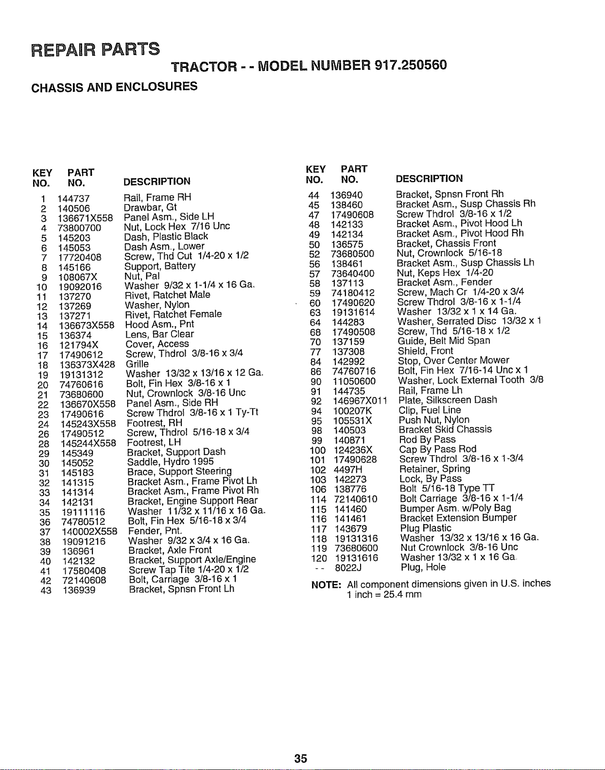
REPAIR PARTS
TRACTOR - - MODEL NUMBER 917.250560
CHASSIS AND ENCLOSURES
KEY PART KEY PART
NO. NO. DESCRIPTION NO. NO. DESCRIPTION
1 144737 Rail, Frame RH 44 136940
2 140506 Drawbar, Gt 45 !38460
3 136671X558 Panel Asmo, Side LH 47 17490608
4 73800700 Nut, Lock Hex 7/16 Unc 48 142133
5 145203 Dash, Plastic Black 49 142134
6 145053 Dash Asm,., Lower 50 136575
7 17720408 Screw, Thd Cut 1/4-20 x 1/2 52 73680500
8 145166 Support, Battery 56 138461
9 108067X Nut, Pal 57 73640400
10 19092016 Washer 9/32 x 1-1/4 x 16 Ga,. 58 137113
11 137270 Rivet, Ratchet Male 59 74180412
12 137269 Washer, Nylon 60 17490620
13 137271 Rivet, Ratchet Female 63 19131614
14 136673X558 Hood Asm. Pnt 64 144283
15 136374 Lens, Bar Clear 68 17490508
16 121794X Cover, Access 70 137159
17 17490612 Screw, Thdrol 3/8-16 x 3/4 77 137308
t8 136373X428 Grille 84 142992
19 19131312 Washer 13/32 x 13/16 x 12 Ga. 86 74760716
20 74760616 Bolt, Fin Hex 3/8-16 x t 90 11050600
21 73680600 Nut, Crowntock 3/8-16 Unc 91 144735
22 136670X558 PanelAsm. Side RH 92 146967X011
23 17490616 ScrewThdrol 3/8-16 x 1 Ty-Tt 94 100207K
24 145243X558 Footrest, RH 95 105531X
26 17490512 Screw, Thdrol 5/16-18 x 3/4 98 140503
28 145244X558 Footrest, LH 99 140871
29 145349 Bracket, Support Dash 100 124236X
30 145052 Saddle, Hydro 1995 101 17490628
31 145183 Brace, Support Steering 102 4497H
32 'I41315 Bracket Asm., Frame Pivot Lh 103 142273
33 141314 Bracket Asm.0 Frame Pivot Rh 106 138776
34 142131 Bracket, Engine Support Rear 114 72140610
35 19111116 Washer 11/32xlli16x16Ga. 115 141460
36 74780512 Bolt, Fin Hex 5/16-18 x 3/4 I16 141461
37 140002X558 Fender, PnL 117 143679
38 19091216 Washer 9/32x3i4x16Ga,. 118 19131316
39 136961 Bracket, Axle Front 119 73680600
40 142132 Bracket, Support Axle/Engine 120 19131616
41 17580408 Screw Tap Tite 1/4-20 x 1/2 - - 8022J
42 72140608 Bolt, Carnage 3/8-16 x 1
43 136939 Bracket, Spnsn Front Lh
Bracket, Spnsn Front Rh
Bracket Asm., Susp Chassis Rh
Screw Thdrol 3/8-16 x 1/2
Bracket Asmo, Pivot Hood Lh
Bracket Asm., Pivot Hood Rh
Bracket, Chassis Front
Nut, Crownlock 5/16-I8
Bracket Asm,., Susp Chassis Lh
Nut, Keps Hex 1/4-20
Bracket Asm,., Fender
Screw, Mach Cr 1/4-20 x 3/4
Screw Thdro! 3/8-16 x 1-1/4
Washer 13/32 x I x 14 Ga.
Washer, Serrated Disc 13/32 x 1
Screw, Thd 5/16-18 x 1/2
Guide, Belt Mid Span
Shield, Front
Stop, Over Center Mower
Bolt, Fin Hex 7/16-14 Unc x 1
Washer, Lock Extemat Tooth 3/8
Rail, Frame Lh
Plate, Sitkscreen Dash
Clip, Fuel Line
Push Nut, Nylon
Bracket Skid Chassis
Rod By Pass
Cap By Pass Rod
Screw Thdrol 3/8-16 x I-3/4
Retainer, Spring
Lock, By Pass
Bolt 5/16-t8 Type TT
Bolt Carriage 3/8-16 x lq/4
Bumper Asm w/Poly Bag
Bracket Extension Bumper
Plug Plastic
Washer t3/32 x 13/16 x 16 Ga.
Nut Crowntock 3/8-16 Unc
Washer 13/32 x 1 x 16 Ga.
Plug, Hole
NOTE: All component dimensions given in U.& inches
1 inch = 2&4 mm
35
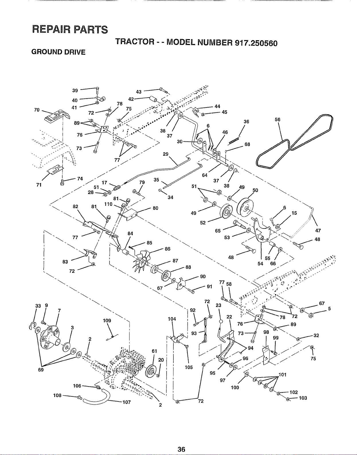
REPAIR PARTS
GROUND DRIVE
TRACTOR -- MODEL NUMBER 917.250560
72
95
97
100
103
36
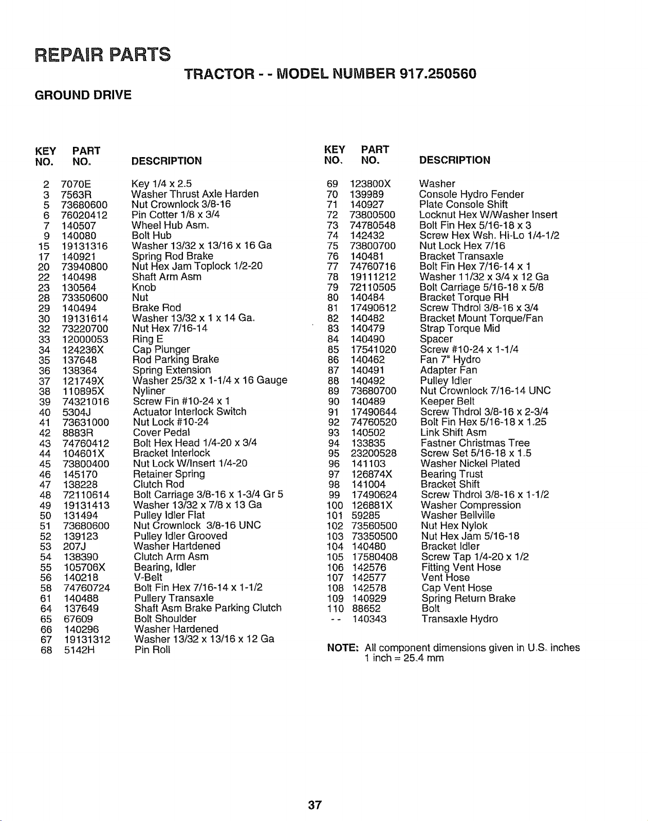
REPAIR PARTS
GROUND DRIVE
TRACTOR - - MODEL NUMBER 917.250560
KEY PART
NO. NO°
2 7070E
3 7563R
5 73680600
6 76020412
7 140507
9 140080
15 19!31316
17 140921
20 73940800
22 140498
23 130564
28 73350600
29 140494
30 19131614
32 73220700
33 12000053
34 124236X
35 137648
36 138364
37 12!749X
38 110895X
39 74321016
40 5304J
4'1 73631000
42 8883R
43 74760412
44 104601X
45 73800400
46 145170
47 138228
48 72110614
49 19131413
50 131494
51 73680600
52 139123
53 207J
54 138390
55 105706X
56 140218
58 74760724
61 140488
64 137649
65 67609
66 140296
67 19131312
68 5142H
DESCRIPTION
Key 1/4 x 2.5
Washer Thrust Axle Harden
Nut Crownlock 3/8-16
Pin Cotter 1/8 x 3/4
Wheel Hub Asmo
Bolt Hub
Washer 13/32 x 13/16 x 16 Ga
Spring Rod Brake
Nut Hex Jam Toplock I/2-20
Shaft Arm Asm
Knob
Nut
Brake Rod
Washer 13/32 x t x 14 Ga,,
Nut Hex 7116-14
Ring E
Cap Plunger
Rod Parking Brake
Spring Extension
Washer 25/32 x 1-t/4 x 16 Gauge
Nyliner
Screw Fin #10-24 x I
Actuator Interlock Switch
Nut Lock #10-24
Cover Pedal
Bolt Hex Head 1/4-20 x 3/4
Bracket Interlock
Nut Lock Wllnsert '1/4-20
Retainer Spring
Clutch Rod
Bolt Carriage 3/8-16 x 1-3/4 Gr 5
Washer 13/32 x 7/8 x ! 3 Ga
Pulley Idler Flat
Nut Crownlock 3/8-i6 UNC
Pulley Idler Grooved
Washer Hartdened
Clutch Arm Asm
Bearing, idler
V-Belt
Bolt Fin Hex 7/16-14 x 1-1/2
Pullery Transaxle
Shaft Asm Brake Parking Clutch
Bolt Shoulder
Washer Hardened
Washer 13/32 x 13/16 x 12 Ga
Pin Roll
KEY PART
NO, NO. DESCRIPTION
69 123800X
70 139989
71 140927
72 73800500
73 74780548
74 142432
75 73800700
76 140481
77 74760716
78 19'111212
79 72110505
80 140484
81 174906'12
82 140482
83 140479
84 140490
85 17541020
86 140462
87 140491
88 140492
89 73680700
90 140489
91 17490644
92 74760520
93 140502
94 133835
95 23200528
96 141103
97 126874X
98 141004
99 17490624
100 126881X
101 59285
102 73560500
103 73350500
104 140480
105 17580408
106 142576
107 142577
108 142578
109 140929
110 88652
-- 140343
Washer
Console Hydro Fender
Plate Console Shift
Locknut Hex W/Washer Insert
Bolt Fin Hex 5/16-18 x 3
Screw Hex Wsho HFLo 1/4-1/2
Nut Lock Hex 7/16
Bracket Transaxle
Bolt Fin Hex 7/16-t4 x 1
Washer 11/32 x 3/4 x 12 Ga
Bolt Carriage 5/16-18 x 5/8
Bracket Torque RH
Screw Thdrol 3/8-I6 x 3/4
Bracket Mount Torque/Fan
Strap Torque Mid
Spacer
Screw #10-24 x 1-1/4
Fan 7" Hydro
Adapter Fan
Pulley Idler
Nut Crownlock 7/16-14 UNC
Keeper Belt
Screw Thdrol 3/8-16 x 2-3/4
Bolt Fin Hex 5/16-18 x 1,25
Link Shift Asm
Fastner Christmas Tree
Screw Set 5/16-18 x 1.5
Washer Nickel Plated
Bearing Trust
Bracket Shift
Screw Thdrot 3/8-16 x t4/2
Washer Compression
Washer Bellvifte
Nut Hex Nytok
Nut Hex Jam 5/16-18
Bracket Idler
Screw Tap 1/4-20 x 1/2
Fitting Vent Hose
Vent Hose
Cap Vent Hose
Spring Return Brake
Bolt
Transaxle Hydro
NOTE," All component dimensions given in U,S, inches
! inch = 25.,4 mm
37
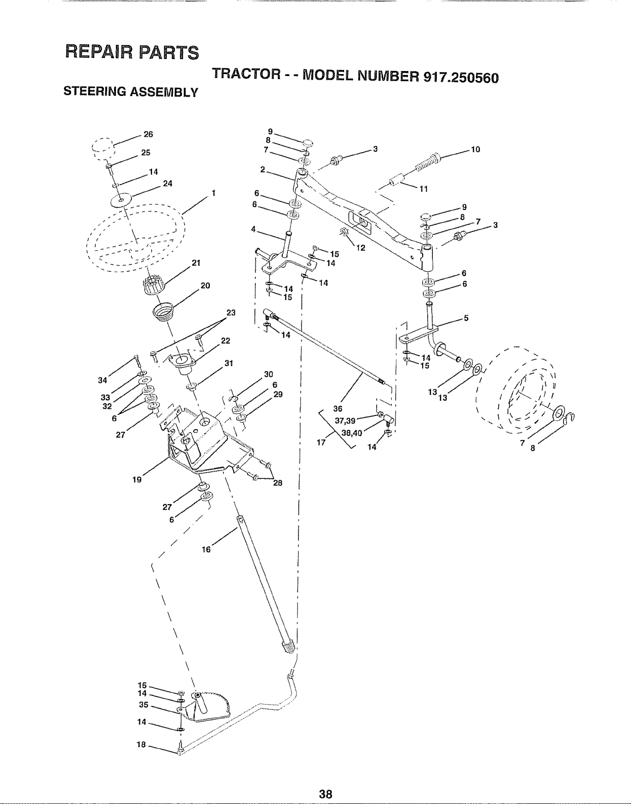
REPAIR PARTS
STEERING ASSEMBLY
TRACTOR - - MODEL NUMBER 917.250560
27
15
t4
19
27
6
/
\
\
/
\
\
\
/
/
16
8 =t_ij
38
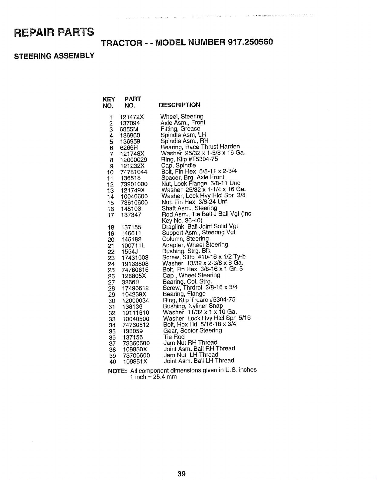
REPARR PARTS
STEERING ASSEMBLY
TRACTOR - - MODEL NUMBER 917.250560
KEY PART
NO. NO. DESCRIPTION
1 121472X
2 137094
3 6855M
4 136960
5 136959
6 6266H
7 121748X
8 12000029
9 121232X
10 74781044
11 136518
12 73901000
13 121749X
14 10040600
15 73610600
16 145103
17 137347
18 137155
19 '146611
2O 145182
21 1007ilL
22 1554J
23 17431008
24 19133808
25 74780616
26 126805X
27 3366R
28 17490612
29 104239X
3O 12000034
31 138136
32 19111610
33 10040500
34 74760512
35 138059
36 137156
37 73360600
38 109850X
39 73700600
4O 109851X
NOTE:
Wheel, Steering
Axle Asm. Front
Fitting, Grease
Spindle Asm, LH
Spindle Asm,, RH
Bearing, Race Thrust Harden
Washer 25/32 x 1-5/8 x 16 Ga.
Ring, Klip #T5304q5
Cap, Spindle
Bolt, Fin Hex 5/8-11 x 2-3/4
Spacer, Brg. Axle Front
Nut, Lock Flange 5/8-11 Unc
Washer 25/32 x 1-1/4 x 16 Ga.
Washer, Lock Hvy Hlcl Spr 3/8
Nut, Fin Hex 3/8-24 Unf
Shaft Asmo, Steering
Rod Asm., Tie Ball J Ball Vgt (Inc.
Key Noo 36-40)
Dragtink, Ball Joint Solid Vgt
Support Asm. Steering Vgt
Column, Steering
Adapter, Wheel Steering
Bushing, Strg, BIk
Screw, SIftp #t0-16 x 1/2 Ty-b
Washer 13/32 x 2-3/8 x 8 Ga.
Bolt, Fin Hex 3/8-16 x I Gr,. 5
Cap, Wheel Steering
Bearing, Col,, Strg,
Screw, Thrdrol 3/8-16 x 3/4
Bearing, Flange
Ring, Klip Truarc #5304-75
Bushing, Nyliner Snap
Washer 11/32 x I x 10 Ga,
Washer, Lock Hvy Hlcl Spr 5/16
Bolt, Hex Hd 5/16-18 x 3/4
Gear, Sector Steering
Tie Rod
Jam Nut RH Thread
Joint Asmo Ball RH Thread
Jam Nut LH Thread
Joint Asm,, Ball LH Thread
All component dimensions given in UoS_inches
1 inch = 25,,4 mm
39
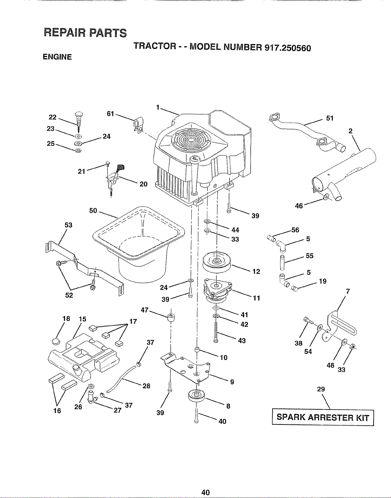
REPAIR PARTS
ENGINE
TRACTOR - - MODEL NUMBER 917.250560
22 c_ 61 ,_
<v
23 "_/_
_ 24
21 "J_J_.._._ 20
53
52
18 15
17
@ @
16
26
37
27
28
/
39
44
33
t
12
11
41
42
43
10
8
4O
2
46
,_®@_ 5
j _s
5 19
7
38
54
48
33
29
\
I SPARK ARRESTER KIT J
40
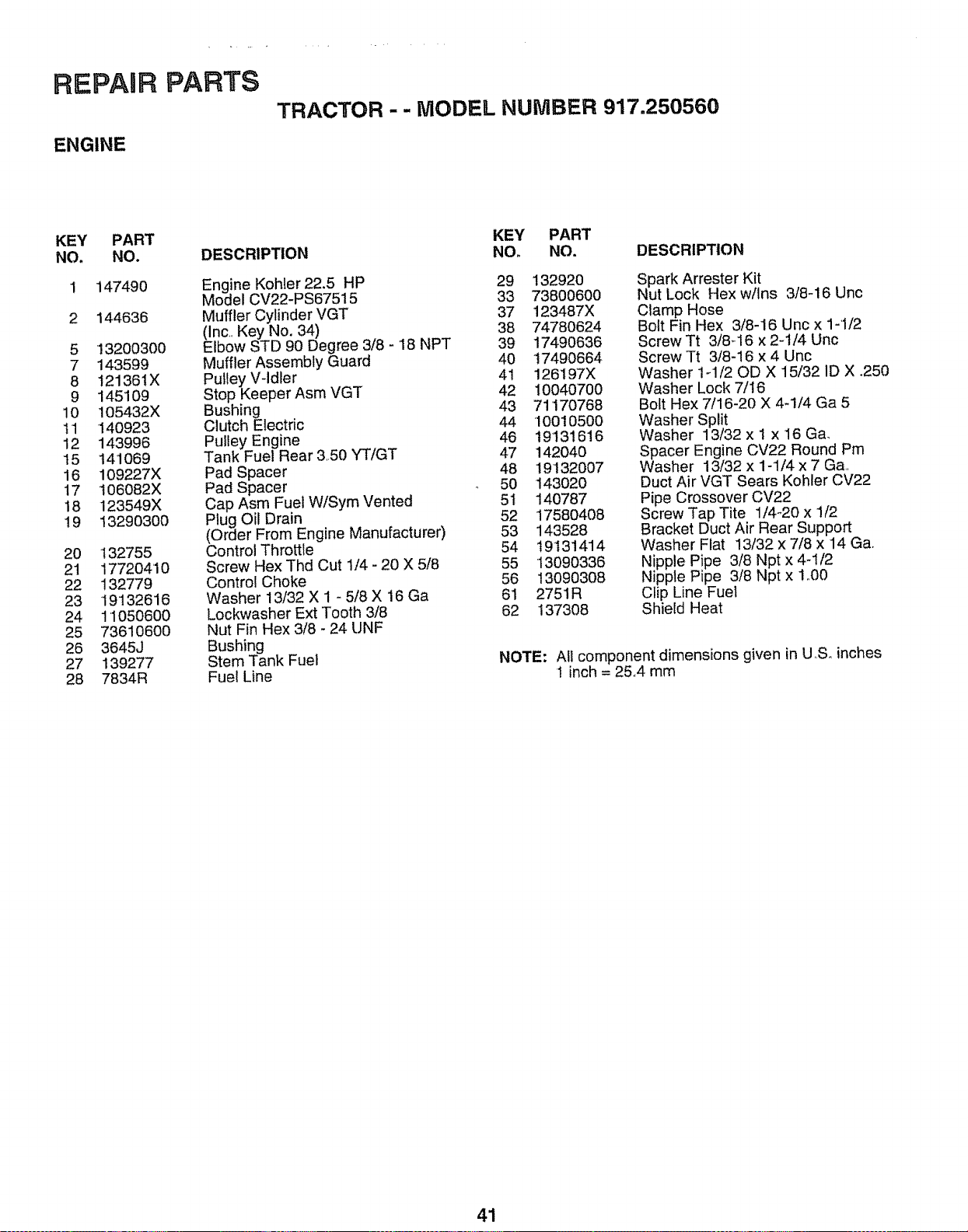
REPAIR
ENGINE
PARTS
TRACTOR - - MODEL NUMBER 917.250560
KEY
NO.
PART
NO.
147490
2 144636
5
7
8
9
10
I1
12
t5
16
17
18
19
20
21
22
23
24
25
26
27
28
13200300
143599
t21361X
145109
105432X
140923
143996
141069
109227X
t06082X
123549X
13290300
132755
177204'10
132779
19132616
1'1050600
73610600
3645J
139277
7834R
DESCRIPTION
Engine Kohler 22,5 HP
Model CV22-PS67515
Muffler Cylinder VGT
(Inc. Key No. 34)
Elbow STD 90 Degree 3/8 - 18 NPT
Muffler Assembly Guard
Pulley V-ldter
Stop Keeper Asm VGT
Bushing
Clutch Electric
Pulley Engine
Tank Fuel Rear 3,,50 "-fTiGT
Pad Spacer
Pad Spacer
Cap Asm Fuel WlSym Vented
Plug Oil Drain
(Order From Engine Manufacturer)
Control Throttle
Screw Hex Thd Cut 1/4 - 20 X 5/8
Control Choke
Washer 13/32 X 1 - 5/8 X 16 Ga
Lockwasher Ext Tooth 3/8
Nut Fin Hex 3/8 - 24 UNF
Bushing
Stem Tank Fuel
Fuel Line
KEY PART
NO. NO. DESCRIPTION
29 132920
33 7380060O
37 123487X
38 74780624
39 17490636
40 17490664
41 126197X
42 10040700
43 71170768
44 10010500
46 19131616
47 142040
48 t9"132007
50 143020
51 140787
52 17580408
53 143528
54 19131414
55 '13090336
56 13090308
61 2751R
62 137308
Spark Arrester Kit
Nut Lock Hex w/Ins 3/8-16 Unc
Clamp Hose
Bolt Fin Hex 3/8-16 Unc x 1-'1/2
Screw Tt 3/8q6 x 2-1/4 Unc
Screw Tt 3/8-16 x 4 Unc
Washer 1-1/20D X 15/32 1D X .250
Washer Lock 7/16
Bolt Hex 7/16-20 X 4_1/4 Ga 5
Washer Split
Washer 13/32 x t x 16 Ga.
Spacer Engine CV22 Round Pm
Washer 13/32 x 1-1/4 x 7 Ga..
Duct Air VGT Sears Kohler CV22
Pipe Crossover CV22
Screw Tap Tite 1/4-20 x 1/2
Bracket Duct Air Rear Support
Washer Flat 13/32 x 7/8 x 14 Ga.
Nipple Pipe 3/8 Npt x 4-1/2
Nipple Pipe 3/8 Npt x 1..00
Clip Line Fuel
Shield Heat
NOTE: All component dimensions given in U,,S. inches
1 inch = 25,,4 mm
41
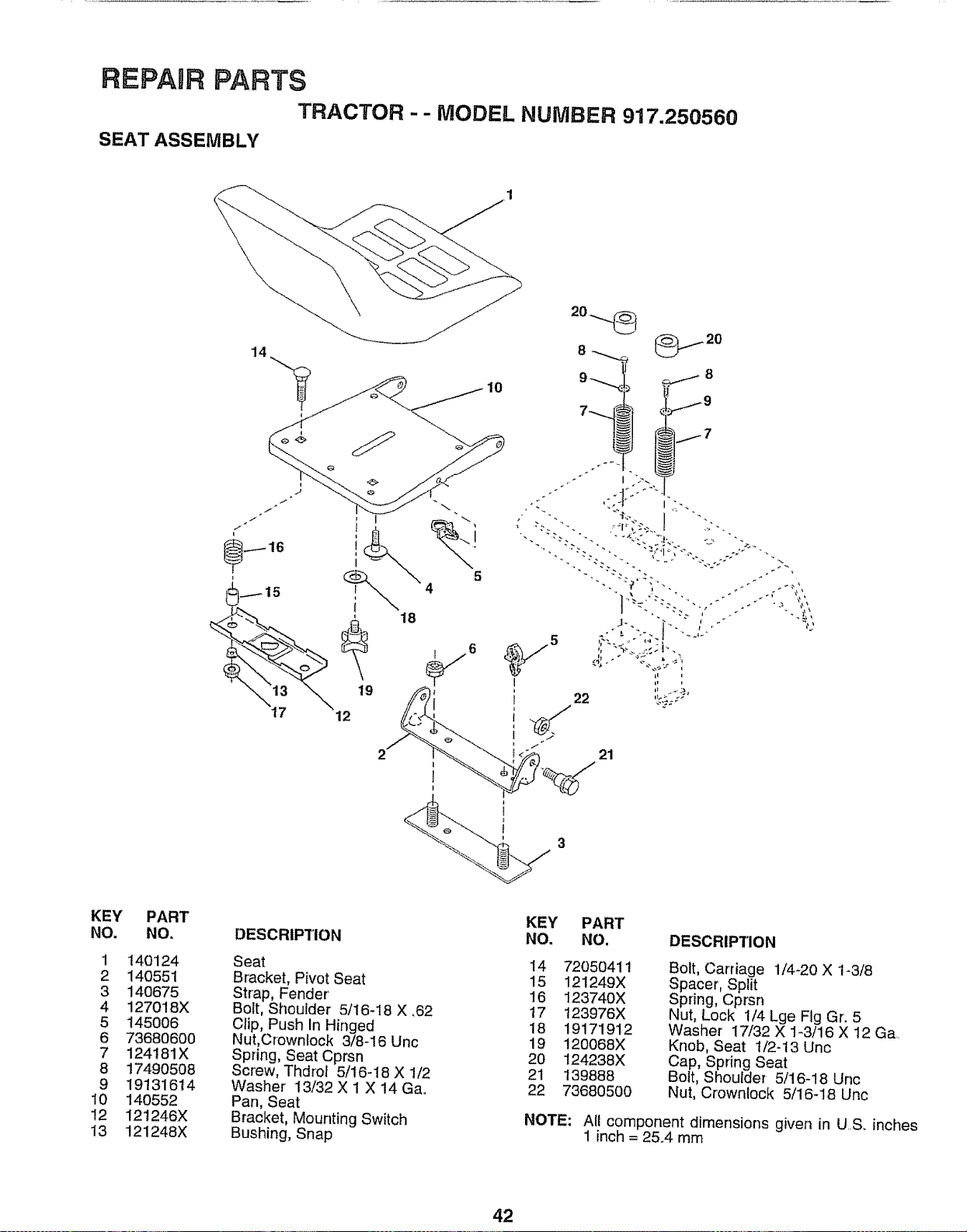
REPAURPARTS
TRACTOR - - MODEL NUMBER 917,250560
SEAT ASSEMBLY
18
19
12
10
5
21
KEY
NO.
1
2
3
4
5
6
7
8
9
10
12
13
PART
NO.
140124
140551
140675
127018X
145006
7368O600
124181X
17490508
19131614
140552
12t246X
121248X
DESCRIPTION
Seat
Bracket, Pivot Seat
Strap, Fender'
Bolt, Shoulder 5/16-18 X ,62
Clip, Push In Hinged
Nut,Crownlock 3/8-16 Unc
Spring, Seat Cprsn
Screw, Thdrol 5/16-i8 X 1/2
Washer' 13/32 X 1 X 14 Ga..
Pan, Seat
Bracket, Mounting Switch
Bushing, Snap
KEY PART
NO. NO.
14 72O50411
15 121249X
16 123740X
t7 123976X
18 19171912
19 120068X
20 124238X
21 139888
22 73680500
DESCRIPTION
Bolt, Carriage 1/4-20 X 1-3/8
Spacer, Split
Spring, Cprsn
Nut, Lock 1/4 Lge Fig Gr. 5
Washer 17/32 X 1-3/16 X 12 Ga..
Knob, Seat 1/2-13 Unc
Cap, Spring Seat
Bolt, Shoulder 5/16-18 Unc
Nut, Crownlock 5/16-18 Unc
NOTE: AU component dimensions given in U.S. inches
1 inch = 25.4 mm
42
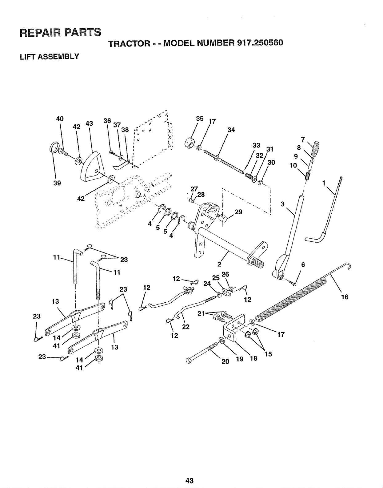
REPAIR PARTS
LIFT ASSEMBLY
TRACTOR - - MODEL NUMBER 917.250560
39
4O
23
12
22
12
15
20 19 18
43
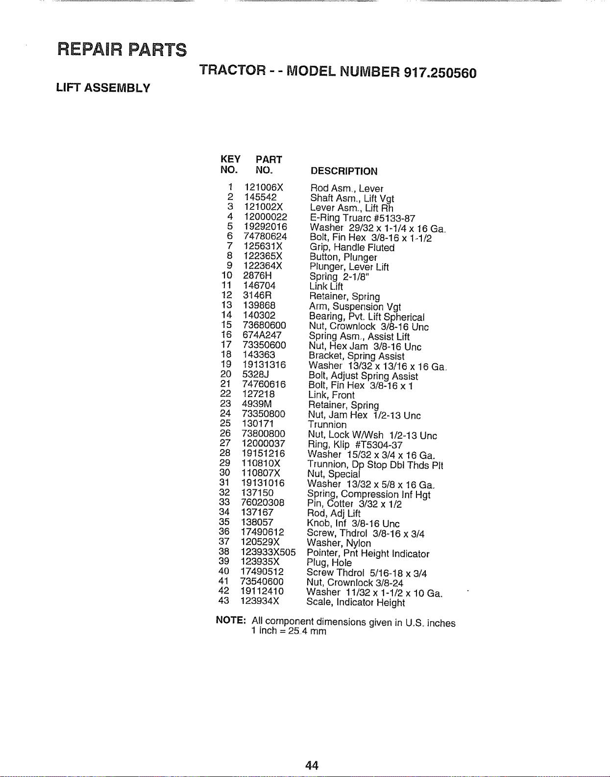
REPAIR PARTS
LIFT ASSEMBLY
TRACTOR - - MODEL NUMBER 917.250560
KEY PART
NO, NO. DESCRIPTION
1 121006X
2 145542
3 121002X
4 12000022
5 19292016
6 74780624
7 125631X
8 122365X
9 122364X
10 2876H
11 1467O4
t2 3146R
13 139868
14 140302
15 73680600
16 674A247
17 73350600
18 143363
19 19131316
20 5328J
2t 74760616
22 127218
23 4939M
24 73350800
25 130171
26 73800800
27 12000037
28 19151216
29 I10810X
30 110807X
31 19131016
32 137150
33 76020308
34 137167
35 138O57
36 17490612
37 120529X
38 123933X505
39 123935X
4O 1749O512
41 73540600
42 1911241O
43 123934X
Rod Asm, Lever
Shaft Asm.., Lift Vgt
Lever Asm.., Lift Rh
E-Ring Truarc #5133-87
Washer- 29/32 x 1-1/4 x 16 Ga.
Bolt, Fin Hex 3/8-16 x 1-1/2
Grip, Handle Fluted
Button, Plunger
Plunger, Lever Lift
Spring 2-1/8"
Link Lift
Retainer, Spring
Arm, Suspension Vgt
Bearing, Pvt. Lift Spherical
Nut, Crownlock 3/8-16 Unc
Spring Asm.., Assist Lift
Nut, Hex Jam 3/8-16 Unc
Bracket, Spring Assist
Washer 13/32 x 13/16 x 16 Ga.
Bolt, Adjust Spring Assist
Bolt, Fin Hex 3/8-16 x 1
Link, Front
Retainer, Spring
Nut, Jam Hex 1/2-13 Unc
Trunnion
Nut, Lock WfWsh 1/2-13 Unc
Ring, Klip #T5304-37
Washer 15/32 x 3/4 x 16 Ga.
Trunnion, Dp Stop Dbl Thds Pit
Nut, Special
Washer 13/32 x 518 x 16 Ga.
Spring, Compression Inf Hgt
Pin, Cotter 3/32 x 1/2
Rod, Adj Lift
Knob, Inf 3/8-16 Unc
Screw, Thdrol 3/8-16 x 3/4
Washer', Nylon
Pointer, Pnt Height Indicator
Plug, Hole
Screw Thdrol 5/16-18 x 3/4
Nut, Crownlock 3/8-24
Washer' 11/32 x 1-1/2 x 10 Ga.
Scale, Indicator Height
NOTE: All component dimensions given in U_S. inches
1 inch = 25..4 mm
44
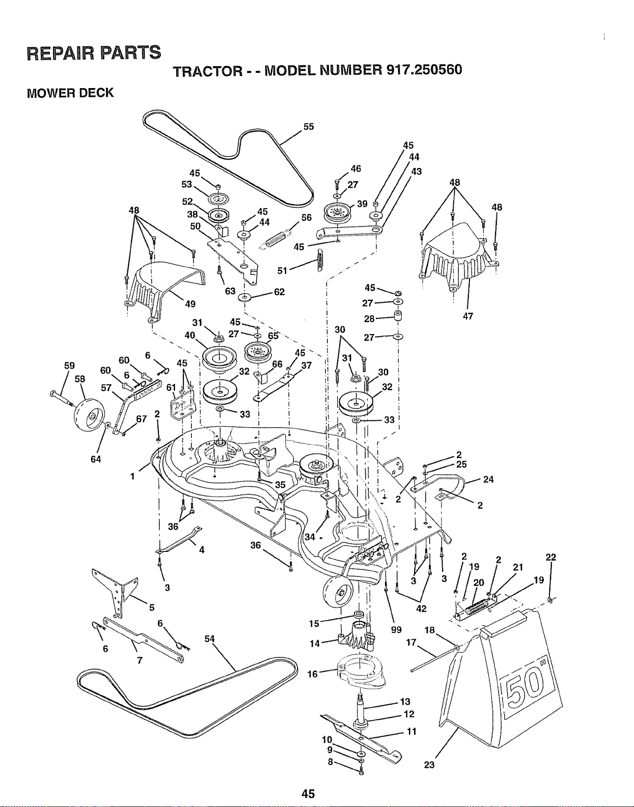
REPARRPARTS
MOWER DECK
TRACTOR -- MODEL NUMBER 917.250569
59
/
64
48
55
45
30
32'
48
48
!
47
24
42
99 18
17
11
23
2 22
45
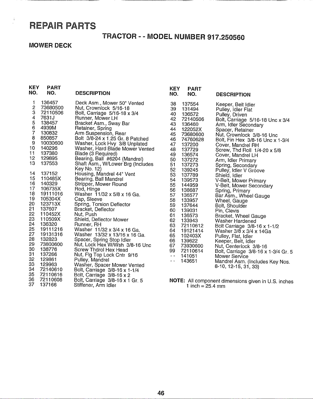
REPAIR PARTS
MOWER DECK
TRACTOR -- MODEL NUMBER 917.250560
KEY PART
NO. NO.
1 136457
2 73680500
3 72110506
4 7631J
5 138457
6 4939M
7 130832
8 850857
9 10030600
10 140296
11 137380
12 129895
13 137553
14 137152
15 1!0485X
16 140329
!7 106735X
18 19111016
19 105304X
20 123713X
21 137607
22 110452X
23 110509X
24 136320
25 19111216
27 19131316
28 132823
29 73800600
30 138776
31 137266
32 129861
33 129963
34 72140610
35 72110616
36 72110608
37 137166
DESCRIPTION
Deck Asm, Mower' 50" Vented
Nut, Crownlock 5/16-18
Bolt, Carriage 5/16-18 x 3/4
Runner, Mower LH
Bracket Asm.., Sway Bar
Retainer, Spring
Arm Suspension, Rear
Bolt 3/8-24 x 1.25 Gr. 8 Patched
Washer, Lock Hvy 3/8 Unplated
Washer, Hard Blade Mower' Vented
Blade (3 Required)
Bearing, Ball #6204 (Mandrel)
Shaft Asm., W/Lower Brg (Includes
Key No. 12)
Housing, Mandrel 44" Vent
Bearing, Ball Mandrel
Stripper, Mower Round
Rod, Hinge
Washer 11/32 x 5/8 x 16 Ga.
Cap, Sleeve
Spring, Torsion Deflector
Bracket, Deflector
Nut, Push
Shield, Deflector Mower
Runner, RH
Washer 11/32 x 3/4 x 16 Ga.
Washer 13/32 x 13/16 x 16 Ga.
Spacer, Spring Stop Idler
Nut, Lock Hex W/Wsh 3/8-16 Unc
Screw Thdrol Hex Head
Nut, Fig Top Lock Cntt 9/16
Pulley, Mandre_
Washer, Spacer Mower Vented
Bolt, Carriage 3/8-!6 x 1-1/4
Bolt, Carriage 3/8-16 x 2
Bolt, Carriage 3/8-16 x l Gr. 5
Stiffener, Arm Edter
KEY PART
NO. NO. DESCRIPTION
38 137554
39 131494
40 136572
42 72140506
43 136460
44 122052X
45 73680600
46 74760628
47 137200
48 137729
49 136574
50 137272
51 137273
52 139245
53 137789
54 139573
55 144959
56 138687
57 136577
58 133957
59 137644
60 139031
61 136573
62 133943
63 72110612
64 19121414
65 102403X
66 139622
67 73930600
99 72110614
-- 141051
-- 143651
Keeper, Belt idler
Pulley, Idler Flat
Pulley, Driven
Bolt, Carriage 5/I6-18 Unc x 3/4
Arm, Idler Secondary
Spacer', Retainer'
Nut, Crownlock 3/8-16 Unc
Bolt, Fin Hex 3/8-16 Unc x 1-3/4
Cover, Mandrel RH
Screw, Thd Roll 1/4-20 x 5/8
Cover, Mandrel LH
Arm, Idler Primary
Spring, Secondary
Pulley, idler V GToove
Shield, Idler
V-Bert, Mower Primary
V-Belt, Mower Secondary
Spring, Primary
Bar Asm., Wheel Gauge
Wheel, Gauge
Bolt, Shoulder
Pin, Clevis
Bracket, Wheel Gauge
Washer' Hardened
Bolt Carriage 3/8-16 x 1-1/2
Washer 3/8 x 3/4 x 14Ga
Pulley, Flat, Idler
Keeper, Belt, Idler
Nut, Centertock 3/8-16
Bolt, Carriage 3/8-16 x 1-3/4 Gr. 5
Mower Service
Mandrel Asm. (Includes Key Nos.
8-10, 12-15, 31, 33)
NOTE: All component dimensions given in U.S. inches
1 inch = 25.4 mm
46
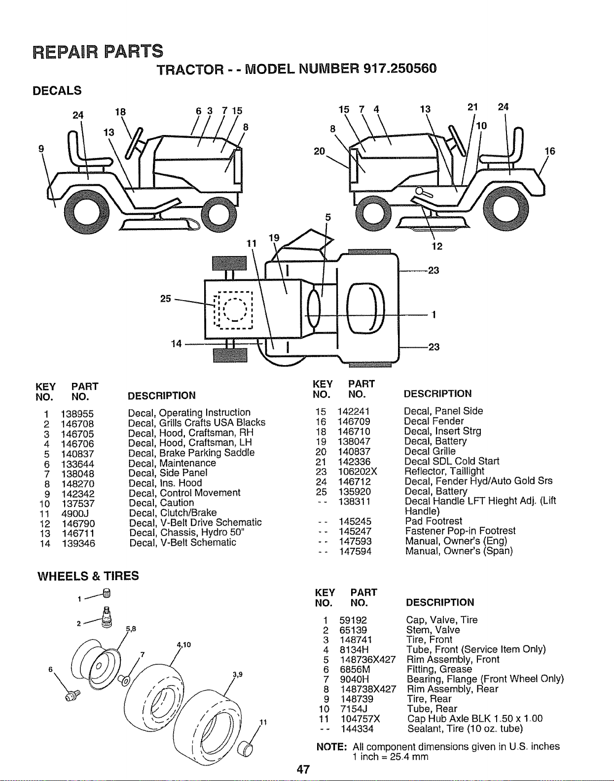
REPAIR
DECALS
24
9
PARTS
TRACTOR - - MODEL NUMBER 917.250560
18 6 3 715 15 7 4 13
\
13 8 8
2O
21 24
16
1
11
5
12
25
14
KEY
NO.
PART
NO.
1 138955
2 146708
3 146705
4 146706
5 140837
6 133644
7 138048
8 14827O
9 142342
10 137537
11 4900J
12 146790
13 146711
14 139346
KEY PART
DESCRIPTION NO. NO.
Decal
Decal
Decal
Decal
Decal
Decal
Decal
Decal
Decal
Decal
Operating Instruction 15 142241
Grills Crafts USA Blacks 16 146709
Hood, Craftsman, RH 18 146710
Hood, Craftsman, LH 19 138047
Brake Parking Saddle 20 140837
Maintenance 21 t42336
Side Panel 23 106202X
Inso Hood 24 146712
Control Movement 25 135920
Caution -- 138311
Decal, Clutch!Brake
Decal, V-Belt Drive Schematic
Decal, Chassis, Hydro 50"
Decal, V-Belt Schematic
WHEELS & TIRES
1I
145245
145247
147593
147594
DESCRIPTION
Decal, Panel Side
Decal Fender
Decal, insert Strg
Decal, Battery
Decal Grille
Decal SDL Cold Start
Reflector, Taillight
Decal, Fender Hyd/Auto Gold Srs
Decal, Battery
Decal Handle LFT Hieght Adjo (Lift
Handle)
Pad Footrest
Fastener Pop-in Footrest
Manual, Owner's (Eng)
Manual, Owner's (Span)
47
KEY
NO.
PART
NO. DESCRIPTION
1
2
3
4
5
6
7
8
9
10
I1
59192
65139
148741
8134H
148736X427
6856M
9040H
t48738X427
148739
7154J
t04757X
144334
NOTE:
Cap, Valve, Tire
Stem, Valve
Tire, Front
Tube, Front (Service Item Only)
Rim Assembly, Front
Fitting, Grease
Bearing, Flange (Front Wheel Only)
Rim Assembly, Rear
Tire, Rear
Tube, Rear
Cap Hub Axle BLK I_50 x 1o00
Sealant, Tire (10 oz,_tube)
All component dimensions given in US inches
1 inch = 2&4 mm
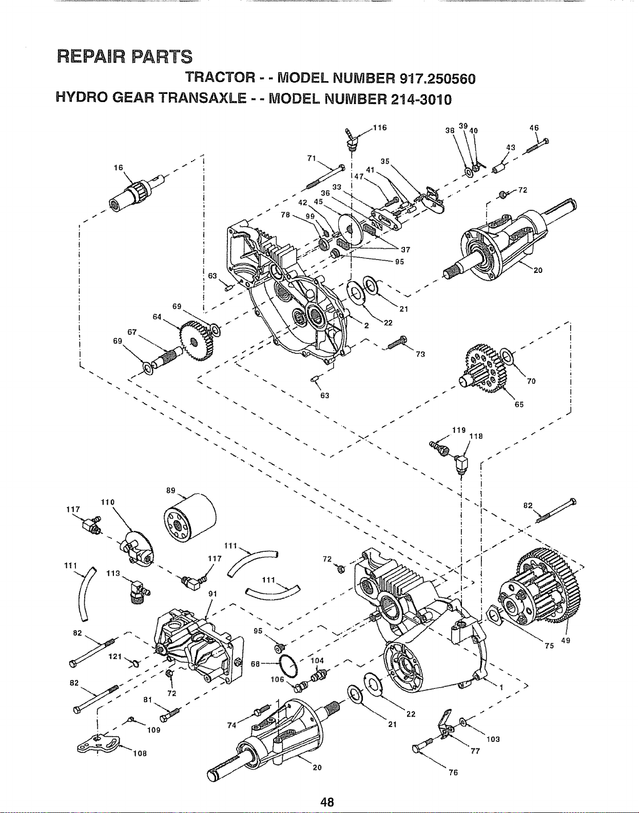
REPAIR PARTS
TRACTOR -- MODEL NUMBER 917.250560
HYDRO GEAR TRANSAXLE -- MODEL NUMBER 214-3010
l
i
i
I
i
i
}
I
I
1
16
j.
t
I
i
l
I
I
t
t
i
63
-- 37
95
I
L
69
73
20
65
119
49
75
76
>
48
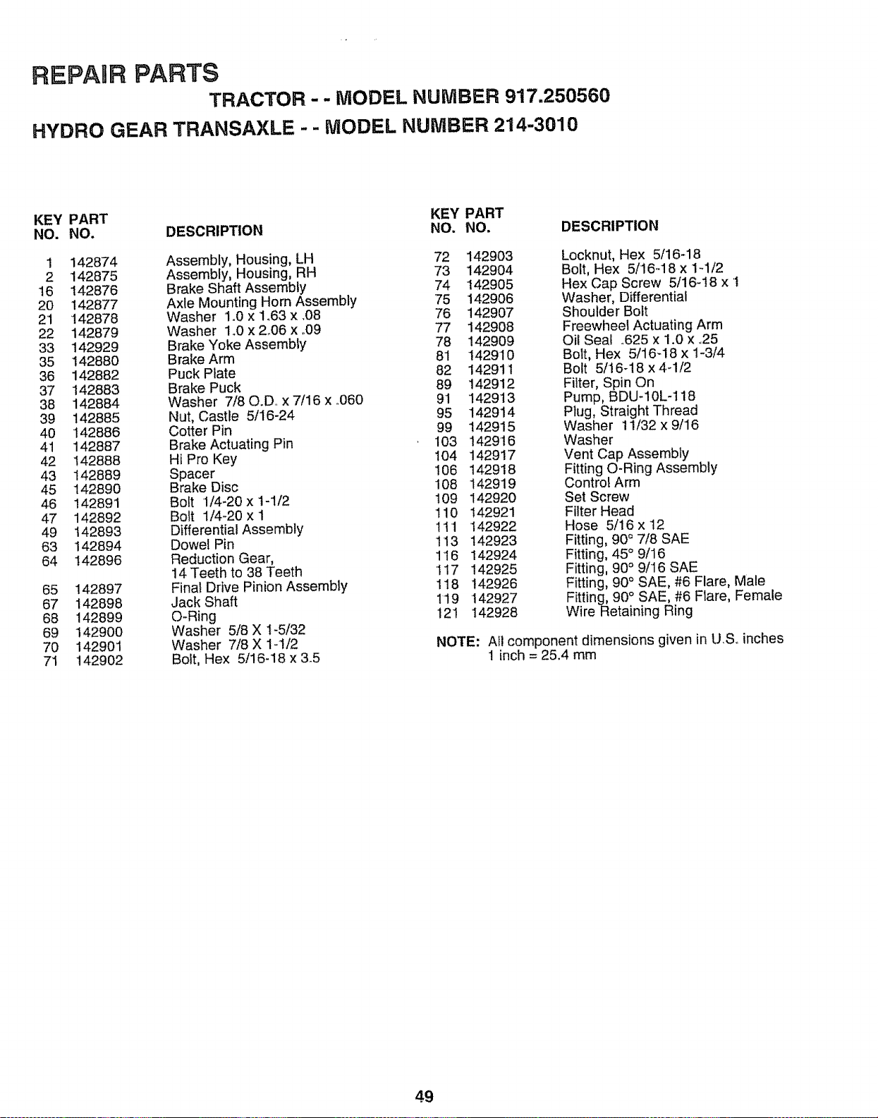
REPAaR PARTS
TRACTOR-- MODEL NUMBER 917.250560
HYDRO GEAR TRANSAXLE - - MODEL NUMBER 214-3010
KEY PART KEY PART
NO. NO. DESCRIPTION NO. NO. DESCRIPTION
1 142874 Assembly, Housing, LH 72 142903
2 142875 Assembly, Housing, RH 73 142904
16 142876 Brake Shaft Assembly 74 I42905
20 142877 Axle Mounting Horn Assembly 75 142906
21 142878 Washer 1.0 x 1o63x.08 76 142907
22 142879 Washer 1.0 x 2_06 x.09 77 142908
33 142929 Brake Yoke Assembly 78 142909
35 142880 Brake Arm 81 142910
36 142882 Puck Plate 82 142911
37 142883 Brake Puck 89 142912
38 142884 Washer 7/80.D.. x 7/16 x .O60 91 142913
39 142885 Nut, Castle 5/16-24 95 142914
40 142886 Cotter Pin 99 !42915
41 142887 Brake Actuating Pin 103 1429'16
42 142888 Hi Pro Key !04 142917
43 142889 Spacer 106 142918
45 142890 Brake Disc 108 142919
46 142891 Bolt 1/4-20 x t-1/2 109 142920
47 142892 Bolt 1/4-20 x I 110 142921
49 142893 Differential Assembly !11 142922
63 142894 Dowel Pin 113 142923
64 142896 Reduction Gear, 116 142924
14 Teeth to 38 Teeth 117 142925
65 142897 Final Drive Pinion Assembly 118 142926
67 142898 Jack Shaft 119 142927
68 142899 O-Ring 121 142928
69 142900 Washer 5/8 X 1-5/32
70 142901 Washer 7/8 X 1-1/2
71 142902 Bolt, Hex 5/16-18 x 3.5
Locknut, Hex 5/16-18
Bolt, Hex 5/16-18 x 1-1/2
Hex Cap Screw 5/16-18 x 'I
Washer, Differential
Shoulder Bolt
Freewheel Actuating Arm
Oil Seal .625 x 1.0 x ..25
Bolt, Hex 5/16-18 x 1-3/4
Belt 5/16-18 x4-1/2
Filter, Spin On
Pump, BDU-10L-118
Plug, Straight Thread
Washer 11/32 x 9/16
Washer
Vent Cap Assembly
Fitting O-Ring Assembly
Control Arm
Set Screw
Filter Head
Hose 5/16 x 12
Fitting, 90 ° 7/8 SAE
Fitting, 45 ° 9/16
Fitting, 90 ° 9/16 SAE
Fitting, 90 ° SAE, #6 Flare, Male
Fitting, 90 ° SAE, #6 Flare, Female
Wire Retaining Ring
NOTE: All component dimensions given in U.So inches
1 inch = 25.4 mm
49
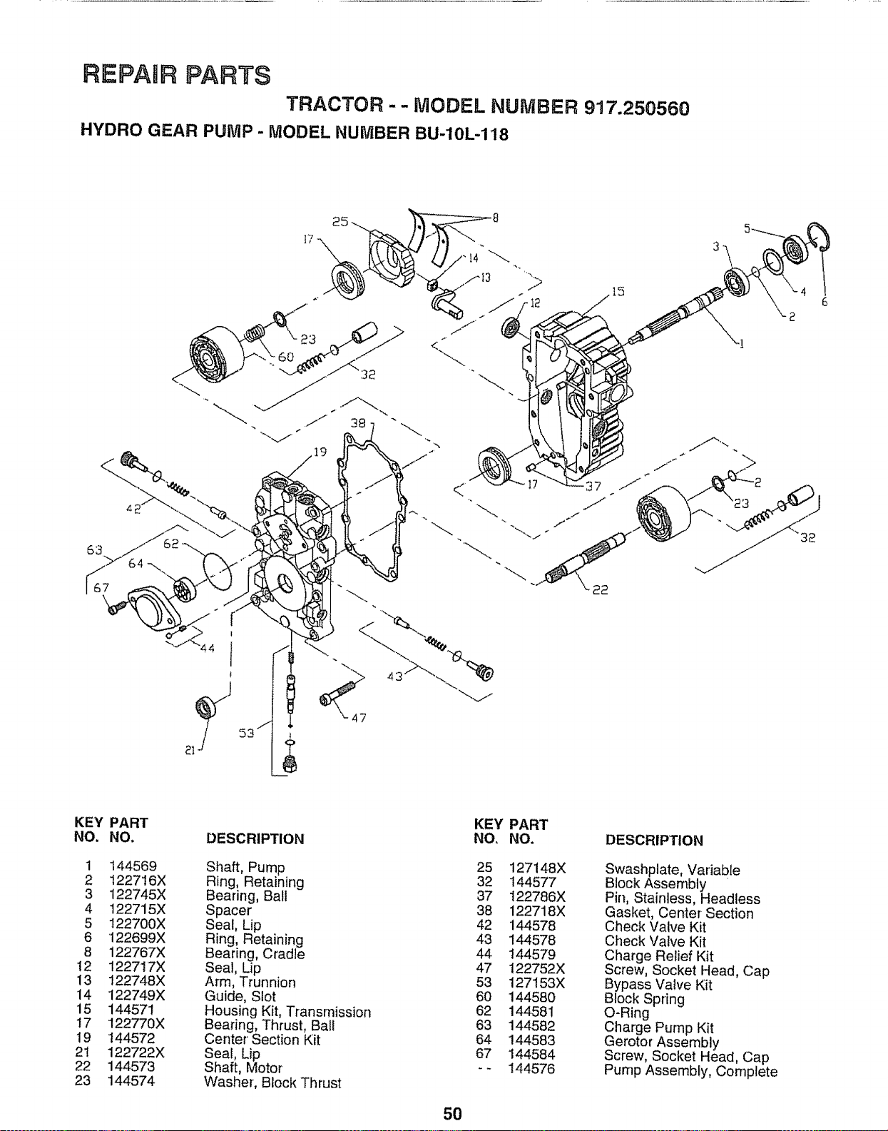
RIEPAJR PARTS
TRACTOR - - MODEL NUMBER 917.250560
HYDRO GEAR PUMP - MODEL NUMBER BU-10L-118
25
_ 44 1 /
,L
J
KEY
NO.
1
2
3
4
5
6
8
t2
13
14
15
17
19
21
22
23
PART
NO.
144569
122716X
122745X
!22715X
122700X
122699X
122767X
122717X
t22748X
122749X
144571
122770X
144572
122722X
144573
144574
DESCRIPTION
Shaft, Pump
Ring, Retaining
Bearing, Ball
Spacer
Seal, Lip
Ring, Retaining
Bearing, Cradle
Seal Lip
Arm, Trunnion
Guide, Slot
Housing Kit, Transmission
Bearing, Thrust, Bali
Center Section Kit
Seal, Lip
Shaft, Motor
Washer, Block Thrust
50
KEY
NO.
25
32
37
38
42
43
44
47
53
60
62
63
64
67
PART
NO.
127148X
144577
t22786X
122718X
144578
144578
144579
122752X
127153X
144580
144581
144582
144583
144584
144576
DESCRIPTION
Swashplate, Variable
Block Assembly "
Pin, Stainless, Headless
Gasket, Center Section
Check Valve Kit
Check Valve Kit
Charge Relief Kit
Screw, Socket Head, Cap
Bypass Valve Kit
Block Spring
O-Ring
Charge Pump Kit
Gerotor Assembly
Screw, Socket Head, Cap
Pump Assembly, Complete
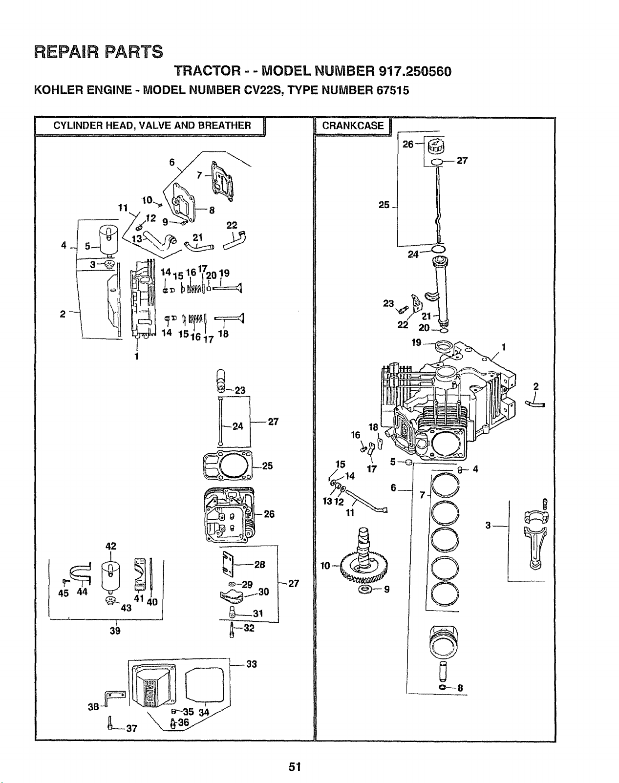
REPAIR PARTS
TRACTOR - - MODEL NUMBER 917,250560
KOHLER ENGINE - MODEL NUMBER CV22S, TYPE NUMBER 67515
CYLINDER HEAD, VALVE AND BREATHER
3__ _ 144=:....,.'16'1720.19[
4 _|
1 151617 18
45 44
42
_--23
39 -_
_27
CRANKCASE
25_
51
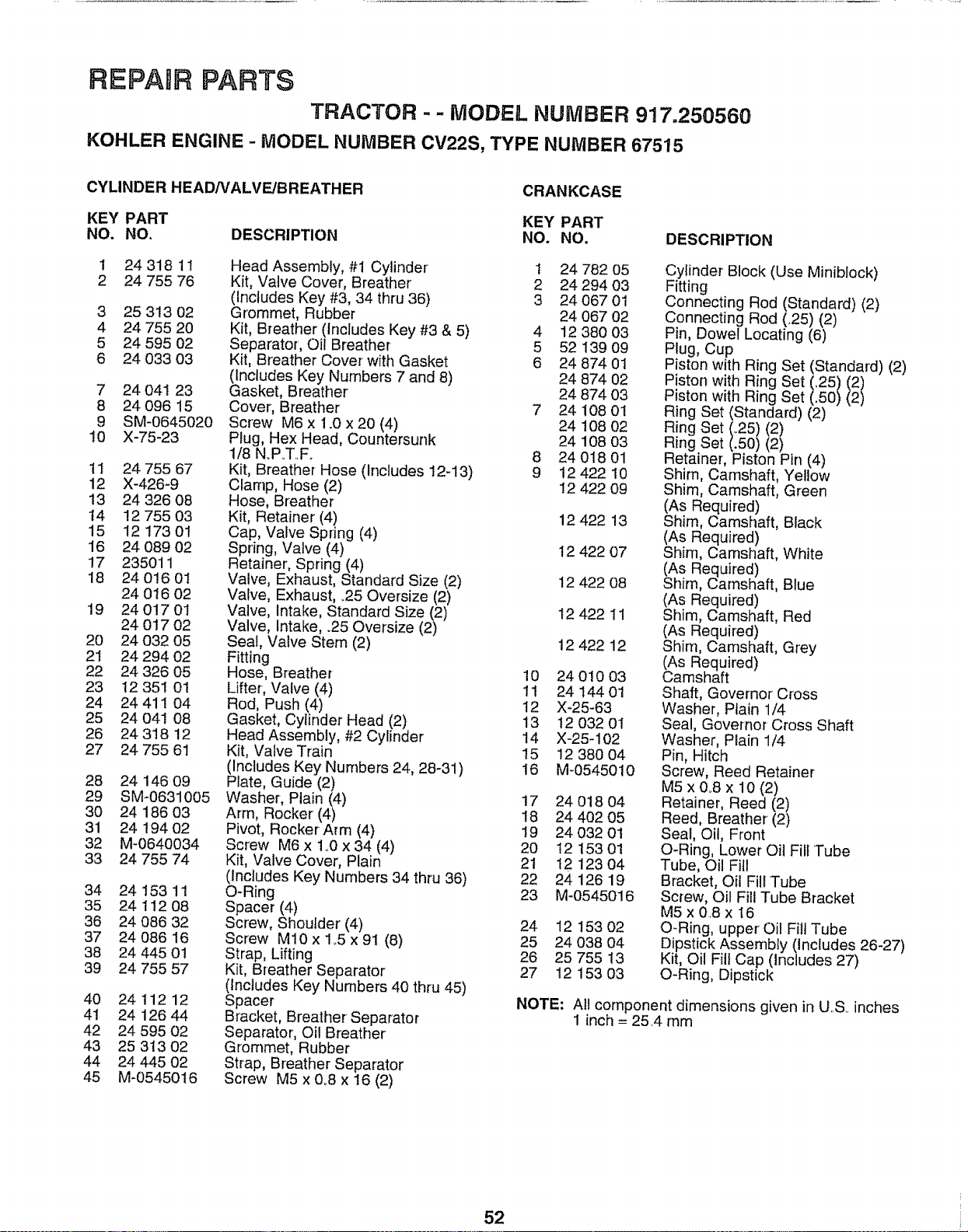
REPADR PARTS
TRACTOR -- MODEL NUMBER 917.250560
KOHLER ENGINE - MODEL NUMBER CV22S, TYPE NUMBER 67515
CYLINDER HEAD/VALVE/BREATHER
CRANKCASE
KEY PART KEY PART
NO, NO, DESCRIPTION NO. NO. DESCRIPTION
1 24 318 11
2 24 755 76
3 25 313 02
4 24 755 20
5 24 595 02
6 24 033 03
7 24 041 23
8 24 096 15
9 SM-0645020
10 X-75-23
11 24 755 67
12 X-426-9
13 24 326 08
14 12 755 03
15 12 173 01
16 24 089 02
17 235011
18 24 0!6 01
24 016 02
19 2401701
24 017 02
20 24 032 05
21 24 294 02
22 24 326 05
23 12 351 01
24 24 411 04
25 24 041 08
26 24 318 12
27 24 755 61
28 24 146 09
29 SM-0631005
30 24 186 03
31 24 194 02
32 M-0640034
33 24 755 74
34 24 153 11
35 24 112 O8
36 24 086 32
37 24 086 16
38 24 445 0!
39 24 755 57
Head Assembly, #1 Cylinder 1 24 782 05
Kit, Valve Cover, Breather 2 24 294 03
(Includes Key #3, 34 thru 36) 3 24 067 01
Grommet, Rubber 24 067 02
Kit, Breather (Includes Key #3 & 5) 4 12 380 03
Separator, Oil Breather 5 52 139 09
Kit, Breather Cover with Gasket 6 24 874 01
(Includes Key Numbers 7 and 8) 24 874 02
Gasket, Breather 24 874 03
Cover, Breather 7 24 108 01
Screw M6 x 1.0 x 20 (4) 24 108 02
Plug, Hex Head, Countersunk 24 108 03
1/8 N.PoT.F.. 8 24 018 01
Kit, Breather Hose (Includes 12-13) 9 12 422 10
Clamp, Hose (2) 12 422 09
Hose, Breather
Kit, Retainer (4) 12 422 13
Cap, Valve Spring (4)
Spring, Valve (4) 12 422 07
Retainer, Spring (4)
Valve, Exhaust, Standard Size (2) 12 422 08
Valve, Exhaust, .25 Oversize (2)
Valve, Intake, Standard Size (2) 12 422 11
Valve, Intake, °25 Oversize (2)
Sea!, Valve Stem (2) 12 422 12
40 24 112 12
41 24 126 44
42 24 595 02
43 25 313 02
44 24 445 02
45 M_0545016
Fitting
Hose, Breather 10
Lifter, Valve (4) 11
Rod, Push (4) 12
Gasket, Cylinder Head (2) 13
Head Assembly, #2 Cylinder 14
Kit, Valve Train 15
(Includes Key Numbers 24, 28-31) 16
Plate, Guide (2)
Washer, Plain (4) 17
Arm, Rocker (4) 18
Pivot, Rocker Arm (4) 19
Screw M6 x 1o0x 34 (4) 20
Kit, Valve Cover, Plain 21
(Includes Key Numbers 34 thru 36) 22
O-Ring 23
Spacer (4)
Screw, Shoulder (4) 24
Screw M10 x 1_5x 91 (8) 25
Strap, Lifting 26
Kit, Breather Separator 27
(includes Key Numbers 40 thru 45)
Spacer
Bracket, Breather Separator
Separator', Oil Breather
Grommet, Rubber
Strap, Breather Separator
Screw M5 x 0..8 x !6 (2)
24 010 03
24 144 01
X_5-63
12 032 01
X-25-102
12 380 04
M_0545010
24 018 04
24 402 05
24 032 01
t2 153 01
t2 123 04
24 126 19
M-0545016
12 153 02
24 038 04
25 755 13
12 153 03
Cylinder' Block (Use Miniblock)
Fitting
Connecting Rod (Standard) (2)
Connecting Rod (,25) (2)
Pin, Dowel Locating (6)
Plug, Cup
Piston with Ring Set (Standard) (2)
Piston with Ring Set (,25)
Piston with Ring Set (.50)/21
Ring Set (Standard) (2)
Ring Set/:25//2 l
Ring Set
Retainer, Piston Pin (4)
Shim, Camshaft, Yellow
Shim, Camshaft, Green
(As Required)
Shim, Camshaft, Black
(As Required)
Shim, Camshaft, White
(As Required)
Shim, Camshaft, Blue
(As Required)
Shim, Camshaft, Red
(As Required)
Shim, Camshaft, Grey
(As Required)
Camshaft
Shaft, Governor Cross
Washer, Plain 1/4
Seal, Governor Cross Shaft
Washer, Plain 1/4
Pin, Hitch
Screw, Reed Retainer
M5 x 0.8 x 10 (2)
Retainer, Reed (2)
Reed, Breather (2)
Seal, Oil, Front
O-Ring, Lower Oil Fill Tube
Tube, Oil Fill
Bracket, Oil Fill Tube
Screw, Oil Fill Tube Bracket
M5 x 08 x 16
O-Ring, upper' Oil Fill Tube
Dipstick Assembly (includes 26-27)
Kit, Oil Fill Cap (Includes 27)
O-Ring, Dipstick
NOTE: All component dimensions given in U_,S,.inches
1 inch = 25,4 mm
52

REPAmB PARTS
TRACTOR - - MODEL NUMBER 917.250560
KOHLER ENGINE - MODEL NUMBER CV22S, TYPE NUMBER 67515
10
21
2o
19
17 14
,iii,
20 19 17 16
2
13"'"
12
11
--8
'8
16
12
53
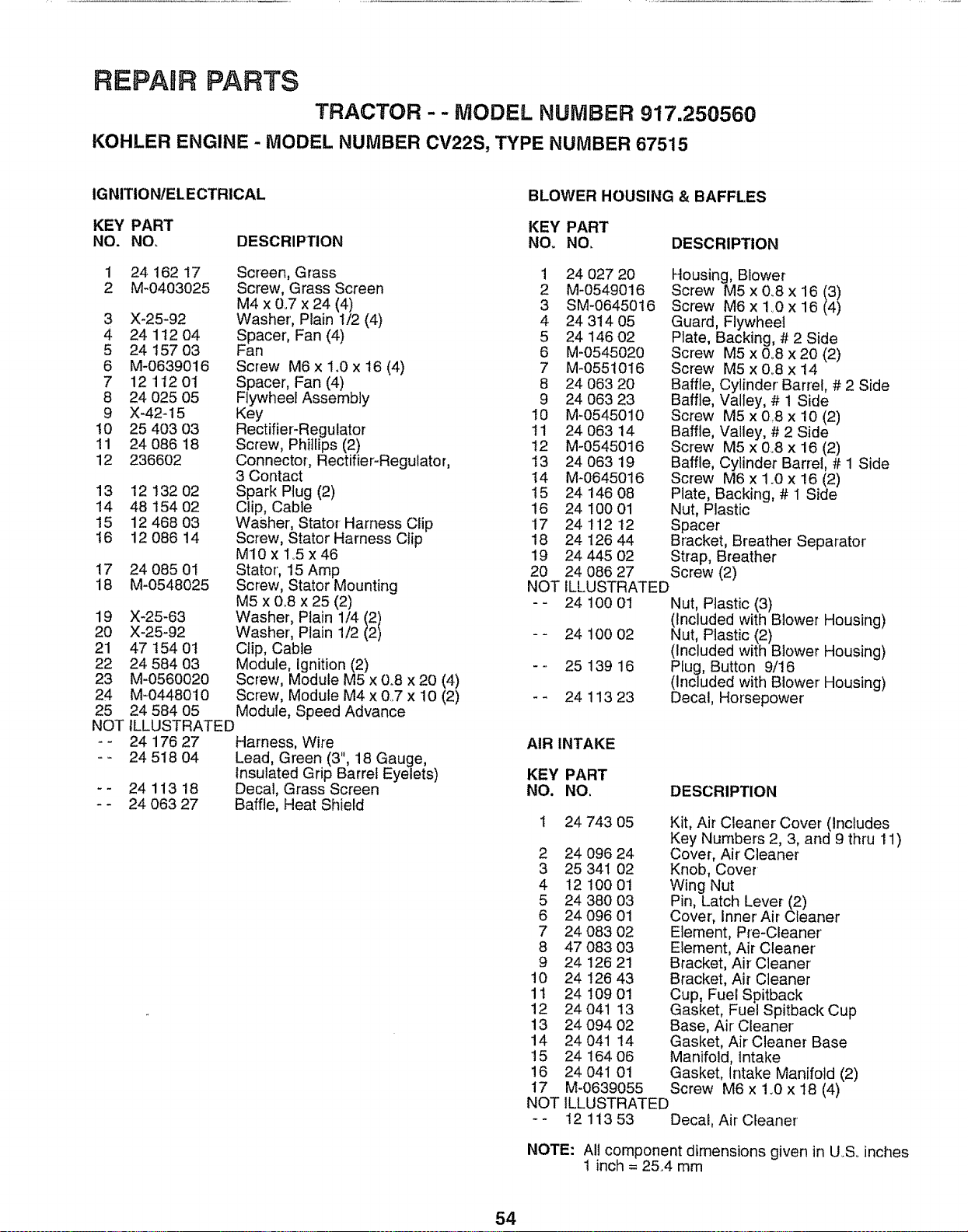
REPAIR PARTS
TRACTOR-- MODEL NUMBER 917.250560
KOHLER ENGINE - MODEL NUMBER CV22S, TYPE NUMBER 67515
IGNITION/ELECTRICAL
BLOWER HOUSING & BAFFLES
KEY PART KEY PART
NO. NO, DESCRIPTION NOo NO, DESCRIPTION
1 24 162 17
2 M-0403025
3 X-25-92
4 24 112 04
5 24 157 03
6 M-0639016
7 12 112 01
8 24 025 05
9 X-42-15
10 25 403 03
! 1 24 O86 18
12 236602
13 12 132 02
14 48 154 02
15 12 468 03
!6 12 O86 14
17 24 085 01
18 M-0548025
Screen, Grass
Screw, Grass Screen
M4 x 0..7x 24 (4)
Washer', Plain 1/2 (4)
Spacer, Fan (4)
Fan
Screw M6 x 1.0 x t6 (4)
Spacer, Fan (4)
Flywheel Assembly
Key
Rectifier-Regulator
Screw, Phillips (2)
Connector, Rectifier-Regulator,
3 Contact
Spark Plug (2)
Clip, Cable
Washer, Stator Harness Clip
Screw, Stator Harness Clip
MIO x 1_5 x 46
Stator, 15 Amp
Screw, Stator Mounting
M5 x 0_8x 25 (2)
Washer, Plain 1/4/2 l
Washer, Plain 1/2
Clip, Cable
Module, Ignition (2)
19 X-25-63
20 X-25-92
21 47 t54 01
22 24 584 03
23 M-0560020
24 M-0448010
25 24 584 05
Screw, Module M5 x 0_8 x 20 (4)
Screw, Module M4 x &7 x 10 (2)
Module, Speed Advance
NOT ILLUSTRATED
- - 24 176 27 Harness, Wire
- - 24 518 04 Lead, Green (3", 18 Gauge,
Insulated Grip Barrel Eyelets)
- - 24 113 18 Decal, Grass Screen
-- 24 063 27 Baffle, Heat Shield
1 24 027 20 Housing, Blower
2 M-0549016 Screw M5 x 0.8 x 16/3)
3 SM-0645016 Screw M6x 1.0 x 16 (4)
4 24 314 05 Guard, Flywheel
5 24 146 02 Plate, Backing, # 2 Side
6 M-0545020 Screw M5 x 0_8 x 20 (2)
7 M-0551016 Screw M5 x 0r8 x 14
8 24 063 20 Baffle, Cylinder Barrel, # 2 Side
9 24 063 23 Baffle, Valley, # 1 Side
10 M-0545010 Screw M5 x 0.8 x 10 (2)
11 24 063 14 Baffle, Valley, # 2 Side
12 M-0545016 Screw M5 x &8 x 16 (2)
13 24 063 19 Baffle, Cylinder Barrel, # 1 Side
t4 M-0645016 Screw M6 x 1.0 x 16 (2)
15 24 146 08 Plate, Backing, # 1 Side
16 24 100 01 Nut, Plastic
17 2411212 Spacer
18 24 126 44 Bracket, Breather Separator
19 24 445 02 Strap, Breather
20 24 086 27 Screw (2)
NOT ILLUSTRATED
-- 24 100 01 Nut, Plastic (3)
(Included with Blower Housing)
- - 24 100 02 Nut, Plastic (2)
(Included with Blower Housing)
- - 25 139 16 Plug, Button 9/16
(Included with Blower Housing)
- - 24 113 23 Decal, Horsepower
AIR INTAKE
KEY PART
NO. NO, DESCRIPTION
24 743 05
2 24 096 24
3 25 34I 02
4 12 100 01
5 24 380 O3
6 24 096 01
7 24 083 02
8 47 083 03
9 24 126 21
10 24 126 43
11 24 109 01
12 24 041 13
13 24 094 02
14 24 041 14
15 24 164 06
16 24 04I 01
17 M-0639055
NOT
Kit, Air Cleaner Cover (includes
Key Numbers 2, 3, and 9 thru 11)
Cover-, Air' Cleaner
Knob, Cover
Wing Nut
Pin, Latch Lever (2)
Cover', Inner Air Cleaner
Element, Pre-Cleaner
Element, Air Cleaner
Bracket, Air' Cleaner
Bracket, Air Cleaner
Cup, Fuel Spitback
Gasket, Fuel Spitback Cup
Base, Air Cleaner'
Gasket, Air Cleaner Base
Manifold, Intake
Gasket, Intake Manifold (2)
Screw M6 x 1.0 x 18 (4)
ILLUSTRATED
12 113 53 Decal, Air Cleaner
NOTE: All component dimensions given in U.So inches
1 inch = 25.4 mm
54
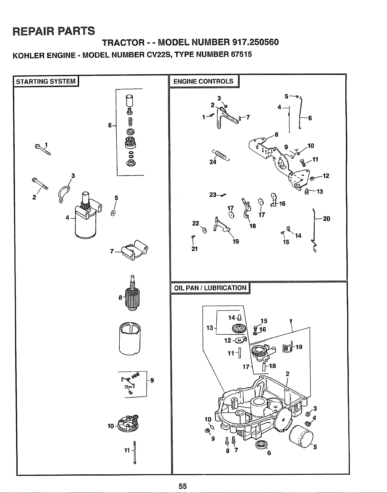
REPAIR PARTS
TRACTOR - - MODEL NUMBER 917.250560
KOHLER ENGINE - MODEL NUMBER CV22S, TYPE NUMBER 67515
_sTA.T,.GS_sTEMi
3
5
/
.
I
I 14-_ 15
13 ff16
17 _18
8 7 6
2
55
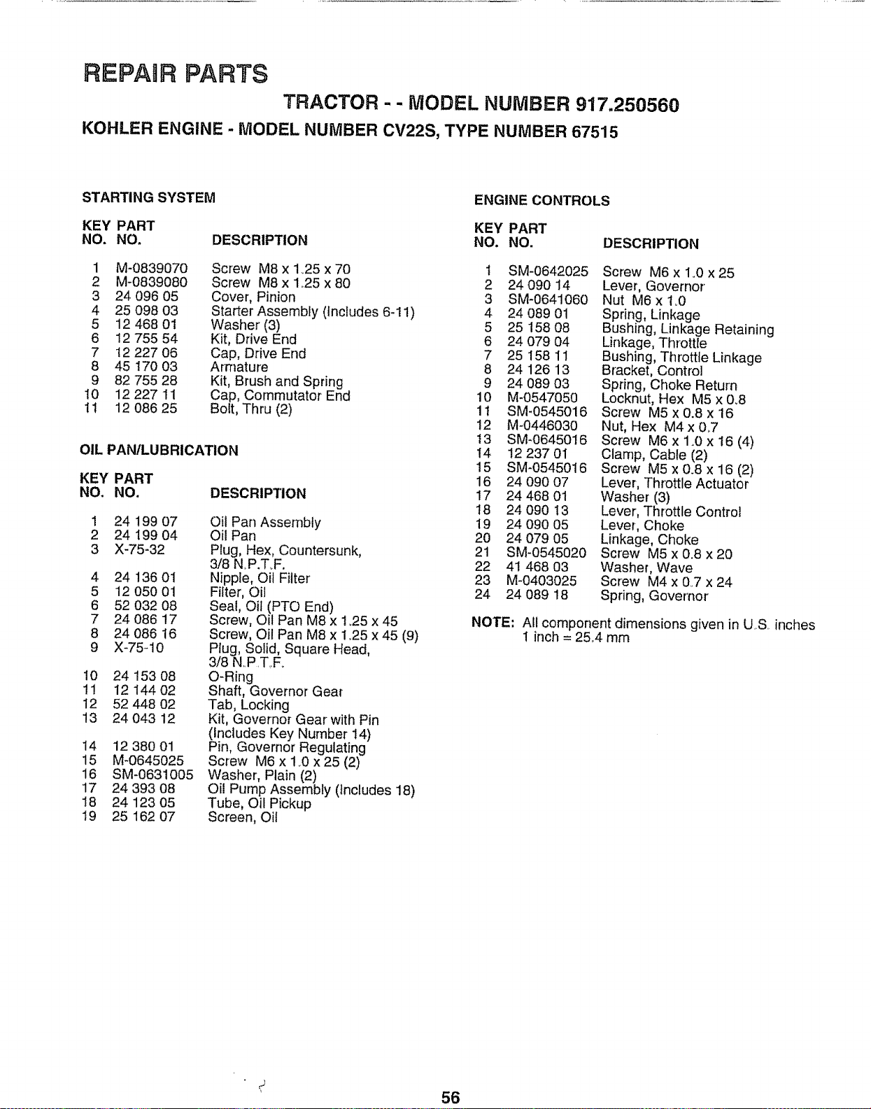
REPAUR PARTS
TRACTOR - - MODEL NUMBER 917.250560
KOHLER ENGINE - MODEL NUMBER CV22S, TYPE NUMBER 67515
STARTING SYSTEM
ENGINE CONTROLS
KEY PART KEY PART
NO. NO. DESCRIPTION NO. NO.
1 M-0839070 Screw M8 x 1_25 x 70
2 M-0839080 Screw M8 x 1.25 x 80
3 24 096 05 Cover, Pinion
4 25 098 03 Starter Assembly (Includes 6-11)
5 12 468 0t Washer (3)
6 !2 755 54 Kit, Drive End
7 !2 227 06 Cap, Drive End
8 45 170 03 Armature
9 82 755 28 Kit, Brush and Spring
10 12 227 11 Cap, Commutator End
11 12 086 25 Bolt, Thru (2)
OIL PANILUBRICATION
DESCRIPTION
KEY PART
NO. NO.
Oil Pan Assembly
Oil Pan
Ptug, Hex, Countersunk,
3/8 N.P.T.F.
Nipple, Oil Filter'
Filter, Oil
Seal, Oil (PTO End)
Screw, Oil Pan M8 x 1.25 x 45
Screw, Oil Pan M8 x 1.25 x 45 (9)
Plug, Solid, Square Head,
3/8 N,,P ITI, Fo
O-Ring
Shaft, Governor Gear
Tab, Locking
Kit, Governor Gear with Pin
(Includes Key Number 14)
Pin, Governor Regulating
Screw M6 x 1.0 x 25 (2)
Washer, Plain (2)
Oil Pump Assembly (includes 18)
Tube, Oil Pickup
Screen, Oil
1 24 199 07
2 24 199 04
3 X-75-32
4 24 136 01
5 12 O50 01
6 52 032 08
7 24 086 17
8 24 086 16
9 X-75-10
10 24 153 O8
11 12 14402
12 52 448 02
13 24 043 12
14 12 380 01
15 M-0645025
16 SM-0631005
17 24 393 08
18 24 123 05
19 25 162 07
DESCRIPTION
t SM-0642025 Screw M6 x 1°0 x25
2 24 090 14 Lever, Governor'
3 SM-0641060 Nut M6xl_0
4 24 089 01 Spring, Linkage
5 25 158 08 Bushing, Linkage Retaining
6 24 079 04 Linkage, Throttle
7 25 I58 11 Bushing, Throttle Linkage
8 24 126 13 Bracket, Control
9 24 089 03 Spring, Choke Return
10 M-0547050 Locknut, Hex M5 x 0°8
11 SM-0545016 Screw M5x0.8x16
12 M-0446030 Nut, Hex M4x 0_7
t3 SM_0645016 Screw M6x1.0x16(4)
14 12 237 01 Clamp, Cable (2)
15 SM-0545016 Screw M5 x 0.8 x 16 (2)
16 24 090 07 Lever, Throttle Actuator
17 24 468 01 Washer (3)
18 24 090 I3 Lever, Throttle Control
19 24 090 05 Lever, Choke
20 24 079 05 Linkage, Choke
21 SM-0545020 Screw M5 x0.8 x20
22 41 468 03 Washer, Wave
23 M-0403025 Screw M4 x 0.7 x 24
24 24 089 18 Spring, Governor
NOTE: All component dimensions given in US. inches
1 inch = 25.4 mm
' 56
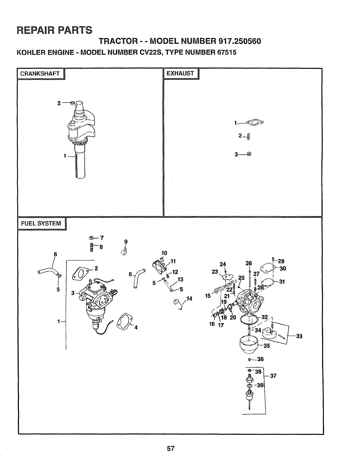
REPAmR PARTS
TRACTOR - - MODEL NUMBER 917.250560
KOHLER ENGINE - MODEL NUMBER CV22S, TYPE NUMBER 67515
,_"A.",_S"AF_=!.............................................EXHAUSTn
24 26
23
16 17
0_36
°-38 - 37
-3_
57
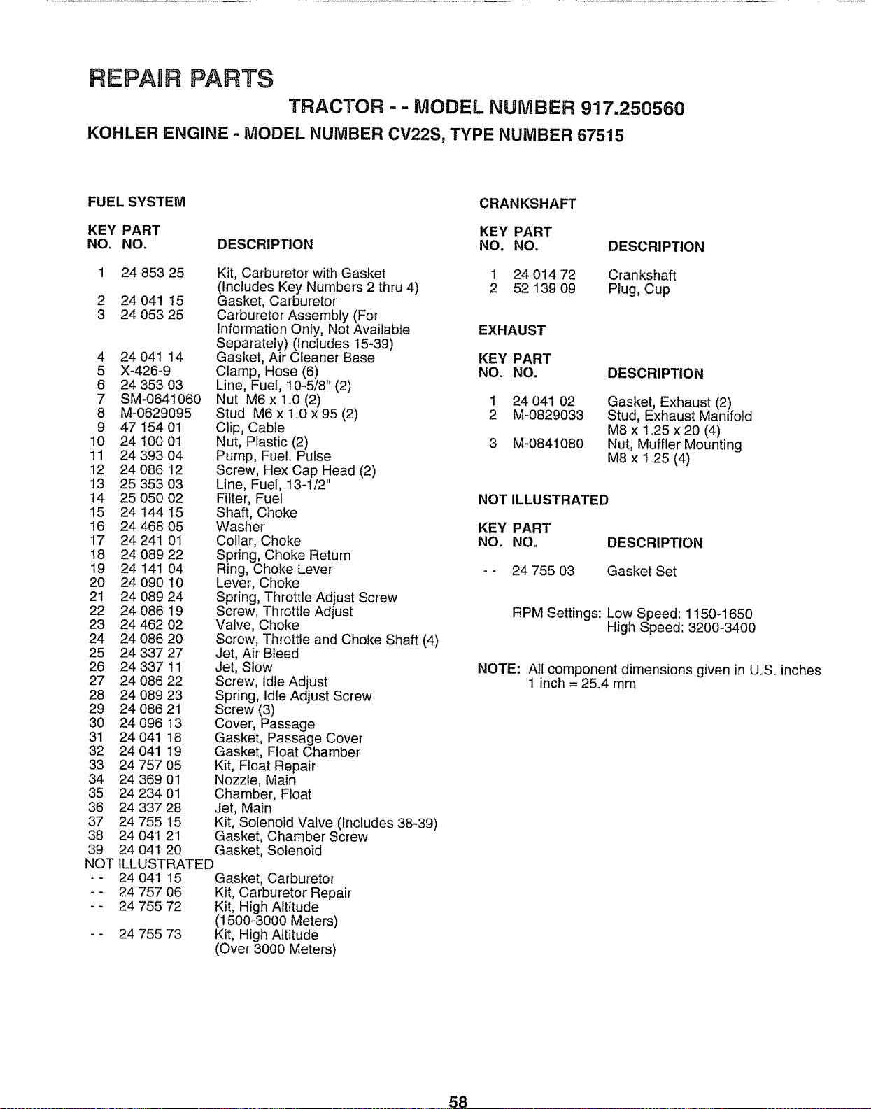
REPAIR PARTS
TRACTOR -- MODEL NUMBER 917.250560
KOHLER ENGINE - MODEL NUMBER CV22S, TYPE NUMBER 67515
FUEL SYSTEM
KEY PART
NO, NO. DESCRIPTION
1
2
3
4
5
6
7
8
9
10
11
12
13
14
15
16
17
!8
19
20
2t
22
23
24
25
26
27
28
29
30
31
32
33
34
35
36
37
38
39
NOT
24 853 25
24 041 15
24 053 25
24 041 14
X-426-9
24 353 03
SM-0641060
M-0629095
47 154 01
24 t00 01
24 393 04
24 086 12
25 353 03
25 050 02
24 144 15
24 468 05
24 241 01
24 089 22
24 141 04
24 090 10
24 089 24
24 086 19
24 462 02
24 086 20
24 337 27
24 337 11
24 086 22
24 089 23
24 086 21
24 096 13
24 041 18
24 041 19
24 757 05
24 369 01
24 234 01
24 337 28
24 755 15
24 04t 21
24 041 20
Kit, Carburetor with Gasket
(Includes Key Numbers 2 thru 4)
Gasket, Carburetor
Carburetor Assembly (For
Information Only, Not AvailabJe
Separately) (includes 15-39)
Gasket, Air Cleaner Base
Clamp, Hose (6)
Line, Fuel, 10-5/8" (2)
Nut M6 x 1.0 (2)
Stud M6 x 1..0 x 95 (2)
Clip, Cable
Nut, Plastic (2)
Pump, Fuel, Pulse
Screw, Hex Cap Head (2)
Line, Fuel, 13-1/2"
Filter, Fuel
Shaft, Choke
Washer'
Collar, Choke
Spring, Choke Return
Ring, Choke Lever
Lever, Choke
Spring, Throttle Adjust Screw
Screw, Throttle Adjust
Valve, Choke
Screw, Throttle and Choke Shaft (4)
Jet, Air Bleed
Jet, Slow
Screw, Idle Adjust
Spring, Idle Adjust Screw
Screw (3)
Cover, Passage
Gasket, Passage Cover
Gasket, Float Chamber
Kit, Float Repair
Nozzle, Main
Chamber, Float
Jet, Main
Kit, Solenoid Valve (Includes 38-39)
Gasket, Chamber Screw
Gasket, Solenoid
ILLUSTRATED
24 041 15 Gasket, Carbureto_
24 757 06 Kit, Carburetor Repair
24 755 72 Kit, High Altitude
(1500-3000 Meters)
24 755 73 Kit, High Attitude
(Over 3000 Meters)
CRANKSHAFT
KEY PART
NO. NO.
I 2401472
2 5213909
DESCRIPTION
Crankshaft
Plug, Cup
EXHAUST
KEY PART
NO. NO.
1 24 041 02
2 M-0829033
3 M-0841080
DESCRIPTION
Gasket, Exhaust (2)
Stud, Exhaust Manifold
M8 x 1.25 x 20 (4)
Nut, Muffler Mounting
M8 x 1.25 (4)
NOT ILLUSTRATED
KEY PART
NO. NO. DESCRIPTION
- - 24 755 03 Gasket Set
RPM Settings: Low Speed: 1150q650
High Speed: 3200-3400
NOTE: All component dimensions given in U..S. inches
1 inch = 2&4 mm
58

SUGGESTED GUIDE FOR SIGHTING SLOPES FOR SAFE OPERATION
ol
_D
SIGHTING
GUIDE
ONLY RIDE UP AND DOWN HILL,
NOT ACROSS HILL
SIGHT AND HOLD THIS LEVEL WITH
SKY LINE OR TREE.
15 ° MAX.
ill JLLIIIIIII iiiii HI II IIIIIIIIJIIIIIIIplIII!PPpPNII I
_i A Operate your Tractor up and down the face of slopes (not
_il A. greater than 15 ), never across the face. Make turns gradu-
lil _ ally to prevent tipping or loss of control. Exercise extreme
_i caution wh?n changing direction on sl0pes.

OWNER'S
MANUAL
MODEL NO.
917.250560
IF YOU NEED
REPAIR SERVICE
OR PARTS:
FOR REPAIR SERVICE, CALL
THIS TOLL FREE NUMBER:
1-800-4-REPAIR
(1-800-473-7247)
FOR REPLACEMENT PARTS
INFORMATION AND
ORDERING, CALL THIS
TOLL FREE NUMBER:
1-800-FON-PART
(1-800-366-7278)
FOR CONSUMER ASSISTANCE
HOT LINE, CALL THIS
TOLL FREE NUMBER:
1-800-659-5917
®
22.5 HP TWIN CYLINDER
ELECTRIC START
50" MOWER
HYDROSTATIC (AUTOMATIC)
GARDEN TRACTOR
Each tractor' has its own model number. Each engine has
its own model number'.
The model number for your tractor witi be found on the
model plate located under the seat.
The model number for' your engine will be found on the
blower housing of the engine.
All parts listed herein may be ordered from any Sears,
Roebuck and Co. Service Center!Department and most Re-
tail Stores.
WHEN ORDERING REPAIR PARTS, ALWAYS GIVE THE
FOLLOWING INFORMATION:
= PRODUCT- TRACTOR
o MODEL NUMBER - 917.250560
• ENGINE MODEL NO. - CV22-PS67515
• PART NUMBER
o PART DESCRIPTION
Your' Sears merchandise has added value when you
consider Sears has service units nationwide staffed with
Sears trained technicians .... professional technicians
specifically trained to insure that we meet our pledge to
you, we service what we sell.
147593 REV. 4 06.26.95 TR
Printed in U.S_A..


