
Operator's
Manual
CRAFTSMAN
LAWN
TRACTORS
WITH
SMART
LAWN
TECHNOLOGY
dT
cinsr-ta4
20.0
HP”
46"
Mower
Electric
Start
Automatic
Transmission
Model
No.
917.27390
*
Espanol,
p.
35
ry
This
product
has
a
low
emission
engine
which
operates
|
differently
from
previously
built
engines.
Before
you
start
the
engine,
read
and
understand
this
manual.
IMPORTANT:
For
answers
to
your
questions
about
this
product,
call:
1-888-331-4569
Craftsman
Customer
Help
Line
Read
and
follow
all
Safety
Rules
and
Instructions
before
operating
this
equipment.
Sears
Brands
Management
Corporation,
Hoffman
Estates,
IL
60179
U.S.A.
Visit
our
Craftsman
website:
www.craftsman.com
*
The
power
rating
as
declared
by
the
engine
manufacturer
is
the
*
La
potencia
nominal
dectarada
por
el
fabricante
del
motor
es
la
average
gross
power
output
at
the
specified
RPM
of
a
typical
salida
media
de
potencia
bruta
a
las
RPM
especificadas
de
un
production
engine
for
the
engine
model
measured
using
SAE
motor
de
serie
tipico
para
el
modelo
de
motor,
medida
segiin
Standards
for
engine
gross power.
Piease
refer
to
the
engine
las
normas
SAE
sobre
potencia
bruta
de
motor.
Para
mas
manufacturer
for
details.
informacion,
consulte
al
fabricante
del
motor.
115868426
Rev.
4
TABLE
OF
CONTENTS
WALTAMY
oo
ceccc
eet
terete
rerneeesereneenteeerene
2
Maintenance
..........ccceseeeeneeeeentereenees
18
Safety
Rules
0...
ee
eeeerenee
3
Service
and
Adjustments........000c
23
Product
Specifications...
eee
6
Storage
........seeeceeeteeeeees
129
Assembly/Pre-Operation
.....0...:
cee
7
~~
Troubleshooting..
30
Operation...
cccececeeeeeeeeeeeaeeeieereeeees
10
Sears
Service
.......
ee
Back
Cover
Maintenance
Schedule...
eee
18
WARRANTY
CRAFTSMAN
LIMITED
WARRANTY
FOR
TWO
YEARS
from
the
date
of
purchase,
all
non-expendable
parts
of
this
riding
equipment
are
warranted
against defects
in
material
or
workmanship.
With
proof
of
purchase,
a
defective
non-expendable
part
will
receive
free
repair.
If
the
part
cannot
be
repaired
it
will
be
replaced
free
of
charge.
Battery
Limited
Warranty
FOR
90
DAYS
from
the
date
of
purchase,
the
battery
(an
expendable
part)
of
this
riding
equipment
is
warranted
against
defects
in
material
or
workmanship.
With
proof
of
purchase,
you
will
receive
a
new
battery
at
no
charge.
You
are
responsible
for
the
labor
cost
of
battery
installation.
Additional
Limited
Warranties
in
the
following
additional
warranties,
you
are
responsible
for
the
labor
cost
of
part
installation
after
the
second
year
from
the
date
of
purchase.
FOR
FIVE
YEARS
from
the
date
of
purchase,
the
frame
of
this
riding
equipment
is
warranted
against
any
defects
in
material
or
workmanship.
With
proof
of
purchase,
you
will
receive
a
new
frame
at
no
charge.
FOR
TEN
YEARS
from
the
date
of
purchase,
the front
axie
of
this
riding
equipment
is
warranted
against
any
defects
in
material
or
workmanship.
With
proof
of
purchase,
you
will
receive
a
new
axle
at
no
charge.
FOR
AS
LONG
AS
IT
IS
USED
by
the
original
owner
after
the
tenth
year
from
the
date
of
purchase,
the
cast
iron
front
axle
(if
equipped)
of
this
riding
equipment
is
warranted
against
any
defects
in
material
or
workmanship.
With
proof
of
purchase,
you
will
receive
a
new
cast
iron
front
axle
at
no
charge.
WARRANTY
SERVICE
For
warranty
coverage
details
to
obtain
free
repair
or
replacement,
visit
the
web
page:
www.craftsman.com/
warranty
Product
Replacement
lf
part
repair
or
replacement
is
impossible,
you
will
receive
a
new
riding
equipment
unit
of
the
same
or
equivalent
model.
Warranty
Restriction
All
warranty
coverage
is
void
if
this
riding
equipment
is
ever
used
while
providing
commercial
services
or
if
rented
to
another
person.
This
warranty
covers
ONLY
defects
in
material
and
workmanship.
Warranty
coverage
does
NOT
include:
+
Expendable
parts
(except
battery)
that
can
wear
out
from
normal
use
within
the
warranty
period,
including
but
not
limited
to
blades,
spark
plugs,
belts
and
air,
oil
or
gas
filters.
+
Standard
maintenance
servicing,
deck
leveling,
oll
changes
and
tune-ups.
*
Tire
replacement
or
repair
caused
by
punctures
from
outside
objects,
such
as
nails,
thorns,
stumps,
or
glass.
*
Tire
or
wheel
replacement
or
repair
resulting
from
normal
wear,
accident,
or
improper
operation
or
maintenance.
+
Repairs
necessary
because
of
operator
abuse,
including
but not
limited
to
damage
caused
by
towing
objects
beyond
the
capability
of
the
riding
equipment,
impacting
objects
that
bend
the
frame,
axle
assembly
or
crankshaft,
or
over-speeding
the
engine.
+
Repairs
necessary
because
of
operator
negligence,
including
but
not
limited
to,
electrical
and
mechanical
damage
caused
by
improper
storage,
failure
to
use
the
proper
grade
and
amount
of
engine
oil,
failure
to
keep
the
deck
clear
of
flammable
debris,
or
failure
to
maintain
the
riding
equipment
according
to
the
instructions
contained
in
the
operator’s
manual.
«
Engine
(fuel
system)
cleaning
or
repairs
caused
by
fuel
determined
to
be
contaminated
or
oxidized
(stale).
In
general,
fuel
should
be
used
within
30
days
of
its
purchase
date.
«
Normal
deterioration
and
wear
of
the
exterior
finishes,
or
product
label
replacement.
This
warranty
gives
you
specific
legal
rights,
and
you
may
aiso
have
other
rights
which
vary
from
state
to
state.
Sears
Brands
Management
Corporation,
Hoffman
Estates,
iL
60179
2
SAFETY
RULES
AXDANGER:
This
cutting
machine
is
capable
of
amputating
hands
and
feet
and
throwing
objects.
Failure
to
observe
the
following
safety
instructions
could
result
in
serious
injury
or
death.
Awarnine:
In
order
to
prevent
acciden-
tal
starting
when
setting
up,
transporting,
adjusting
or
making
repairs,
always
discon-
nect
spark
plug wire
and
place
wire
where
it
cannot
contact
spark
plug.
AAWARNING:
Do
not
coast
down
a
hill
in
neutral,
you
may
lose
control
of
the
tractor.
AAWARNING:
Tow
only
the
attachments
that
are
recommended
by
and
comply
with
specifications
of
the
manufacturer
of
your
tractor.
Use
common
sense
when
towing.
Operate
only
at
the
lowest
possible
speed
when onaslope.
Too
heavy
ofa
load,
while
on
a
slope,
is
dangerous.
Tires
can
lose
traction
with
the
ground
and
cause
you
to
lose
control
of
your
tractor.
AWARNING:
Engine
exhaust,
some
of
its
constituents,
and
certain
vehicle
compo-
nents
contain
or
emit
chemicals
known
to
the
State
of
California
to
cause
cancer
and
birth
defects
or
other
reproductive
harm.
Awarnine:
Battery
posts,
terminals
and
related
accessories
contain
lead
and
lead
compounds,
chemicals
known
to
the
State
of
California
to
cause
cancer
and
birth
defects
or
other
reproductive
harm.
Wash
hands
after
handling.
|.
CHILDREN
A@\WARNING!
CHILDREN
CAN
BE
IN-
JURED
BY
THIS
EQUIPMENT.
The
Ameri-
can
Academy
of
Pediatrics
recommends
that
children
be
a
minimum
of
12
year
of
age
before
operating
a
pedestrian
controlled
lawn
mower
and
a
minimum
of
16
years
of
age
before
operating
a
riding
lawn
mower.
AWARNING!
CHILDREN
CAN
BE
SERIOUSLY
INJURED
OR
KILLED
BY
THIS
EQUIPMENT.
Carefully
read
and
follow
all
of
the
safety
instructions
below.
Tragic
accidents
can
occur
if
the
operator
is
not
alert
to
the
presence
of
children.
Children
are
often
attracted
to
the
machine
and
the
mowing
activity.
Never
assume
that
children
will
remain
where
you
last
saw
them.
Keep
children
out
of
the
mowing
area
and
in
the
watchful
care
of
a
responsible
adult
other
than
the
operator.
Be
alert
and
turn
machine
off
if
a
child
enters
the
area.
Before
and
while
backing,
look
behind
and
down
for
small
children.
Never
carry
children,
even
with
the
blades
shut
off.
They
may
fall
off
and
be
seriously
injured
or
interfere
with
safe
machine
operation.
Children
who
have
been
given
rides
inthe
past
may
suddenly
appear
in
the
mowing
area
for
another
ride
and
be
run
over
or
backed
over
by
the
machine.
Never
allow
children
to
operate
the
ma-
chine.
Use
extreme
caution
when
approaching
blind
corners,
shrubs,
trees,
or
other
objects
that
may
biock
your
view
of
a
child.
-
GENERAL
OPERATION
Read,
understand,
and
follow
all
instruc-
tions
on
the
machine
and
in
the
manual
before
starting.
Do
not put
hands
or
feet
near
rotating
parts
or
under
the
machine.
Keep
clear
of
the
discharge
opening
at
all
times.
Only
allow
responsible
adults,
who
are
familiar
with
the
instructions,
to
operate
the
machine.
Clear
the
area
of
objects
such
as
rocks,
toys, wire,
etc.,
which
could
be
picked
up
and
thrown
by
the
blades.
Ensure
the
area
is
clear
of
bystanders
before
operating.
Stop
machineifanyone
enters
the
area.
Never
carry
passengers.
Do
not
mow
in
reverse
unless
absolutely
necessary.
Always
look
down
and
behind
before
and
while
backing.
Never
direct
discharged
material
toward
anyone.
Avoid
discharging
material
against
a
wall
or
obstruction.
Material
may
ricochet
back
toward
the
operator.
Stop
the
blades
when
crossing
gravel
surfaces.
Do
not
operate
machine
without
the
entire
grass
catcher,
discharge
chute,
or
other
safety
devices
in
place
and
working.
SAFETY
RULES
*
Slow
down
before
turning.
«
Never
leave
a
running
machine
unat-
tended.
Always
turn
off
blades,
set
parking
brake,
stop
engine,
and
remove
keys
before
dismounting.
*
Disengage
blades
when
not
mowing.
Shut
off
engine
and
wait
for
all
parts
to
come
to
acomplete
stop
before
cleaning
the
machine,
removing
the
grass
catcher,
or
unclogging
the
discharge
chute.
*
Operate
machine
only
in
daylight
or
good
artificial
light.
«
Donot
operate
the
machine
while
under
the
influence
of
alcohol
or
drugs.
*
Watch
for
traffic
when
operating
near
or
crossing
roadways.
«
Use
extreme
caution
when
loading
or
unloading
the
machine
into
a
trailer
or
truck.
*
Always
wear
eye
protection
when
operat-
ing
machine.
*
Use
ear
protectors
to
avoid
damage
to
hearing.
*
Data
indicates
that
operators, age
60
years
and
above,
are
involved
in
alarge
percentage
of
riding
mower-related
inju-
ries.
These
operators
should
evaluate
their
ability
to
operate
the
riding
mower
safely
enough
to
protect
themselves
and
others
from
serious
injury.
*
Followthe
manufacturer's
recommenda-
tion
for
wheel
weights
or
counterweights.
*
Keep
machine
free
of
grass,
leaves
or
other
debris
build-up
which
can
touch
hot
exhaust
/
engine
parts
and
burn.
Do
not
allow
the
mower
deck
to
plow
leaves
or
other
debris
which
can
cause
build-up
to
occur.
Clean
any
oil
or
fuel
spillage
before
operating
or
storing
the
machine.
Allow
machine
to
cool
before
storage.
lil,
SLOPE
OPERATION
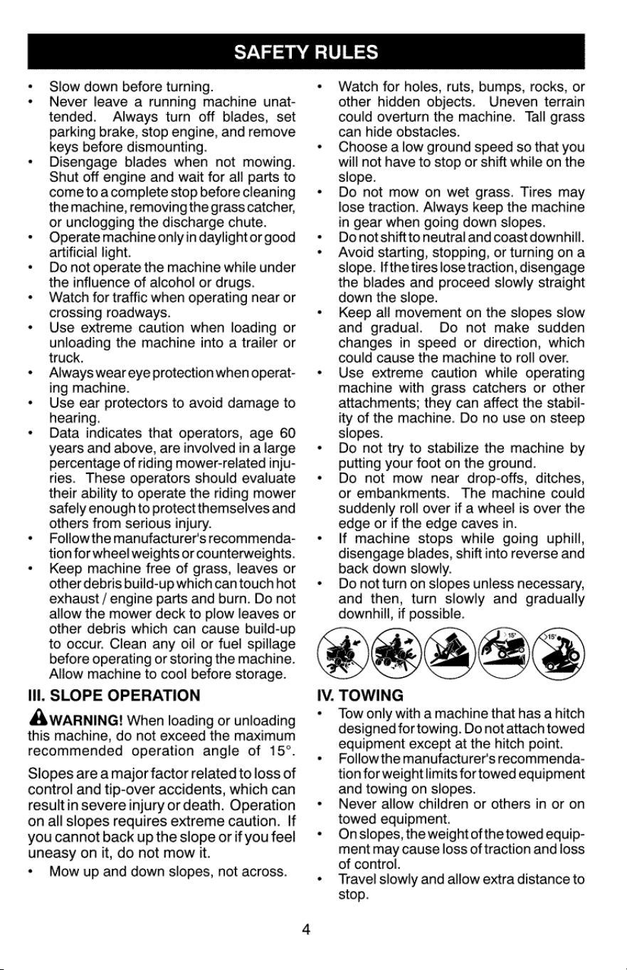
Awarnine!
When
loading
or
unloading
this
machine,
do
not
exceed
the
maximum
recommended
operation
angle
of
15°.
Slopes
are
a
major
factor
related
to
loss
of
control
and
tip-over
accidents,
which
can
result
in
severe
injury
or
death.
Operation
on
all
slopes
requires
extreme
caution.
If
you
cannot
back
up
the
slope
or
if
you
feel
uneasy
on
it,
do
not
mow
it.
*
Mow
up
and
down
slopes,
not
across.
IV.
Watch
for
holes,
ruts,
bumps,
rocks,
or
other
hidden
objects.
Uneven
terrain
could
overturn
the
machine.
Tall
grass
can
hide
obstacles.
Choose
a
low
ground
speed
so
that
you
will
not
have
to
stop
or
shift
while
on
the
slope.
Do
not
mow
on
wet
grass.
Tires
may
lose traction.
Always
keep
the
machine
in
gear
when
going
down
slopes.
Do
not
shiftto
neutral
and
coast
downhill.
Avoid
starting,
stopping,
or
turning
ona
slope.
Ifthe
tires
lose
traction,
disengage
the
blades
and
proceed
slowly
straight
down
the
slope.
Keep
all
movement
on
the
slopes
slow
and
gradual.
Do
not
make
sudden
changes
in
speed
or
direction,
which
could
cause
the
machine
to
roll
over.
Use
extreme
caution
while
operating
machine
with
grass
catchers
or
other
attachments;
they
can
affect
the
stabil-
ity
of
the
machine.
Do
no
use
on
steep
slopes.
Do
not
try
to
stabilize
the
machine
by
putting
your
foot
on
the
ground.
Do
not
mow
near
drop-offs,
ditches,
or
embankments.
The
machine
could
suddenly
roll
over
if
a
wheel
is
over
the
edge
or
if
the
edge
caves
in.
If
machine
stops
while
going
uphill,
disengage
blades,
shift
into
reverse
and
back
down
slowly.
Do
not
turn
on
siopes
unless
necessary,
and
then,
turn
slowly
and
gradually
downhill,
if
possible.
TOWING
Tow
only
with
a
machine
that
has
a
hitch
designed
for
towing.
Do
not
attach
towed
equipment
except
at
the
hitch
point.
Follow
the
manufacturer's
recommenda-
tion
for
weight
limits
for
towed
equipment
and
towing
on
slopes.
Never
allow
children
or
others
in
or
on
towed
equipment.
Onslopes,
the
weight
of
the
towed
equip-
ment
may
cause
loss
of
traction
and
loss
of
control.
Travel
slowly
and
allow
extra
distance
to
stop.

SAFETY
RULES
GENERAL
SERVICE
V.
SERVICE
SAFE
HANDLING
OF
GASOLINE
To
avoid
personal
injury
or
property
dam-
age,
use
extreme
care
in
handling
gasoline.
Gasoline
is
extremely
flammable
and
the
vapors
are
explosive.
Extinguish
all
cigarettes,
cigars,
pipes,
and
other
sources
of
ignition.
Use
only
approved
gasoline
container.
Never
remove
gas cap
or
add
fuel
with
the
engine
running.
Allow
engine
to
cool
before
refueling.
Never
fuel
the
machine
indoors.
Never
store
the
machine
or
fuel
container
where
there
is
an
open
flame,
spark,
or
pilot light
such
as
on
a
water
heater
or
other
appliances.
Never
fill
containers
inside
a
vehicle
or
on
a
truck
or
trailer
bed
with
plastic
liner.
Always
place
containers
on
the
ground
away
from
your
vehicle
when
filling.
Remove
gas-powered
equipment
from
the
truck
or
trailer
and
refuel
it
on
the
ground.
If
this
is
not
possible,
then
refuel
such
equipmentwith
a
portable
container,
rather
than
from
a
gasoline
dispenser
nozzle.
Keep
the
nozzle
in
contact
with
the
rim
of
the
fuel
tank
or
container
opening
at
all
times
until
fueling
is
complete.
Do
not
use
a
nozzle
lock-open
device.
Iffuel
is
spilled
on
clothing,
change
cloth-
ing
immediately.
Never
overfill
fuel
tank.
Replace
gas
cap
and
tighten
securely.
Never
operate
machine
in
a
closed
area.
Keep
all
nuts
and
bolts
tight
to
ensure
the
equipment
is
in
safe
working
condition.
Never
tamper
with
safety
devices.
Never
interfere
with
the
intended
function
of
a
safety
device
or
reduce
the
protection
provided
by
a
safety
device.
Check
there
proper
operation
regularly.
NEVER
oper-
ate
a
machine
with
a
safety
device
that
does
not
function
properly.
Keep
machine
free
of
grass,
leaves,
or
other
debris
build-up.
Clean
oil
or
fuel
spillage
and
remove
any
fuel-soaked
debris.
Allow
machine
to
cool
before
storing.
If
you
strike
a
foreign
object,
stop
and
inspectthe
machine.
Repair,
ifnecessary,
before
restarting.
Never
make
any
adjustments
or
repairs
with
the
engine
running.
Check
grass
catcher
components
andthe
discharge
chute
frequently
and
replace
with
manufacturer's
recommended
parts,
when
necessary.
Mower
blades
are
sharp.
Wrap
the
blade
or
wear
gloves,
and
use
extreme
caution
when
servicing
them.
Check
brake
operation
frequently.
Adjust
and
service
as
required.
Maintain
or
replace
safety
and
instruction
labels,
as
necessary.
Use
ear
protectors
to
avoid
damage
to
hearing.
Paarl
eC
an
Sedo
Always
wear
eye
protection
when
operating
machine.

PRODUCT
SPECIFICATIONS
Gasoline
Capacity
3
Gallons/11,35
L
and
type:
Regular
Unleaded
*
Oil
Type:
SAE
30
(above
32°F/0°C)
(API:
SJ-SN)
SAE
5W30
(below
32°F/0°C)
Oil
Capacity:
W/
Filter:
64
02./1,89
L
W/out
Filter:
60
Oz./1,77
L
Spark
Plug:
Champion
RC12YC
(Gap:
.030°/0,76
mm)
16
Amps
@
3600
RPM
Charging
System:
Battery:
Amp/Hr:
28
Min.
CCA:
230
Case
size:
UiR
Blade
Bolt
Torque:
45-55
Ft.
Los./62-75
Nm
Gasoline
containing
up
to
10%
ethanol
(E10)
is
acceptable
for
use
in
this
machine.
The
use
of
any
gasoline
exceeding
10%
ethanol
(E10)
will
void
the
product
warranty.
CONGRATULATIONS
on
your
purchase
of
a
new
tractor.
It
has
been designed,
engi-
neered
and
manufactured
to
give
you
the
best
possible
dependability
and
performance.
Should
you
experience
any
problem
you
can-
not
easily
remedy,
please
contact
a
Sears
or
other
qualified
service
center.
We
have
com-
petent,
well-trained
representatives
and
the
proper
tools
to
service
or
repair
this
tractor.
Please
read
and
retain
this
manual.
The
instructions
will
enable
you
to
assemble
and
maintain
your
tractor
properly.
Always
observe
the
“SAFETY
RULES”.
CUSTOMER
RESPONSIBILITIES
*
Read
and
observe
the
safety
rules.
*
Follow
a
regular
schedule
in
maintaining,
caring
for
and
using
your
tractor.
*
Follow
instructions
under
“Maintenance”
and
“Storage”
sections
of
this
manual.
*
Wear
proper
Personal
Protective
Equip-
ment
(PPE)
while
operating
this
machine,
including
(at
a
minimum)
sturdy
footwear,
eye
protection,
and
hearing
protection.
Do
not
mow
in
shorts
and/or
open
toed
footwear.
*
Always
letsomeone
know
you
are
outside
mowing.
AWARNING:
This
tractor
is
equipped
with
aninternal
combustion
engine
and
should
not
be
used
on
or
near
any
unimproved
forest-
covered,
brush-covered
or
grass-covered
land
unless
the
engine’s
exhaust
system
is
equipped
with
a
spark
arrester
meeting
applicable
local
or
state
laws
(if
any).
Ifa
spark
arrester
is
used,
itshould
be
maintained
in
effective
working
order
by
the
operator.
Inthe
state
of
Californiathe
above
is
required
by
law
(Section
4442
of
the
California
Public
Resources
Code).
Other
states
may
have
similar
laws.
Federal
laws
apply
on
federal
lands.
A
spark
arrester
for
the
muffler
is
available
through
your
nearest
Sears
service
center
(See
ENGINE
ASSEMBLY
section
of
this
manual).
REPAIR
PROTECTION
AGREEMENTS
Congratulations
on
making
a
smart
purchase.
Your
new
Craftsman®
product
is
designed
and
manufactured
for
years
of
dependable
operation.
But
like
all
products,
it
may
require
repair
from
time
to
time.
That’s
when
having
a
Repair
Protection
Agreement
can
save
you
money
and
aggravation.
Here’s
what
the
Repair
Protection
Agreement*
includes:
Expert
service
by
experienced
service
technicians
trusted
in
millions
of
homes
every
year.
Unlimited
service
and
no
charge
for
parts
and
labor
on
all
covered
repairs.
Product
replacement
up
to
$1500
if
your
covered
product
can’t
be
fixed.
Discount
of
25%
from
regular
price
of
service
and
related
installed
parts
not
covered
by
the
agreement.
Fast
help
by
phone
—
phone
support
from
a
service
agent
on
all
products
to
help
troubleshoot
problems.
Think
of
us
as
a
“talking
owner’s
manual.”
Once
you
purchase
the
Repair
Protection
Agreement,
a
simple
phone
call
is
all
that
it
takes
for
you
to
schedule
service.
You
can
call
anytime
day
or
night.
The
Repair
Protection
Agreement
is
a
risk-free
purchase.
If
you
cancel
for
any
reason
during
the
product
warranty
period,
we
will
provide
a
full
refund.
Or,
a
prorated
refund
anytime
after
the
product
warranty
period
expires.
Purchase
your
Repair
Protection
Agreement
today!
Some
limitations
and
exclusions
apply.
For
prices
and
additional
information
call
1-800-827-6655.
Sears
Installation
Service
For
Sears
professional
installation
of
home
appliances,
garage
door
openers,
water
heaters,
and
other
major
home
items,
call
1-888-331-4569.
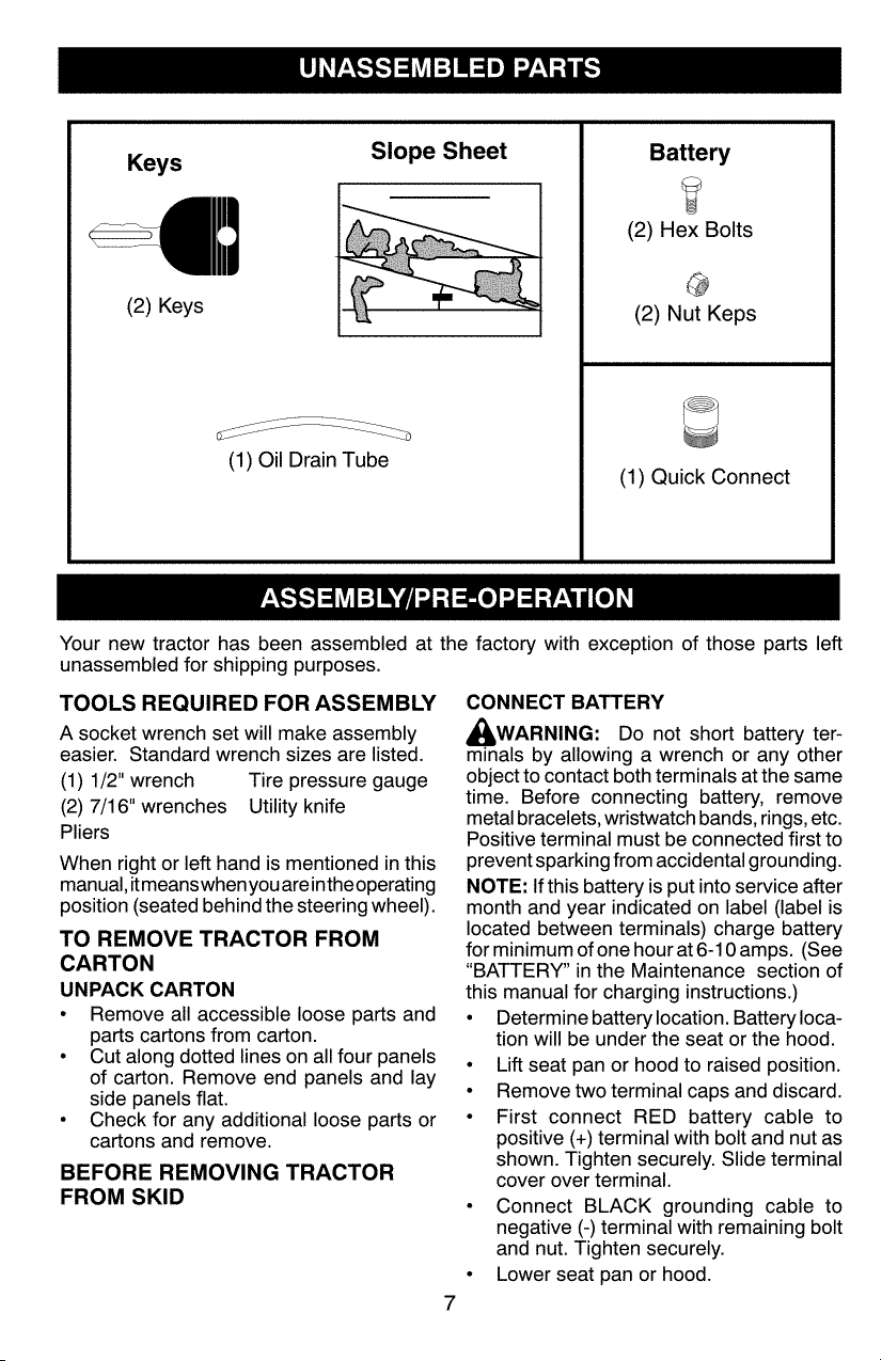
UNASSEMBLED
PARTS
Keys
Slope Sheet
Battery
2)
Keys
(1)
Oil
Drain
Tube
e
a
(2)
Hex
Bolts
@
(2)
Nut
Keps
(1)
Quick
Connect
ASSEMBLY/PRE-OPERATION
Your
new
tractor
has
been
assembled
at
the
factory
with
exception
of
those
parts
left
unassembled
for
shipping
purposes.
TOOLS
REQUIRED
FOR
ASSEMBLY
A
socket
wrench
set
will
make
assembly
easier.
Standard
wrench
sizes
are
listed.
(1)
1/2"
wrench
Tire
pressure
gauge
(2)
7/16"
wrenches
—
Utility
knife
Pliers
When
right
or
left
hand
is
mentioned
in
this
manual,
itmeanswhen
youare
inthe
operating
position
(seated
behind
the
steering
wheel).
TO
REMOVE
TRACTOR
FROM
CARTON
UNPACK
CARTON
*
Remove
all
accessible
loose
parts
and
parts
cartons
from
carton.
*
Cut
along
dotted
lines
on
all
four
panels
of
carton.
Remove
end
panels
and
lay
side
panels
flat.
*
Check
for
any
additional
loose
parts
or
cartons
and
remove.
BEFORE
REMOVING
TRACTOR
FROM
SKID
CONNECT
BATTERY
Awaarnine:
Do
not
short
battery
ter-
minals
by
allowing
a
wrench
or
any
other
object
to
contact
both
terminals
at
the
same
time.
Before
connecting
battery,
remove
metal
bracelets,
wristwatch
bands,
rings,
etc.
Positive
terminal
must
be
connected
first to
prevent
sparking
from
accidental
grounding.
NOTE:
If
this
battery
is
put
into
service
after
month
and
year
indicated
on
label
(label
is
located
between
terminals)
charge
battery
for
minimum
of
one
hour
at6-10
amps.
(See
“BATTERY?”
in
the
Maintenance
section
of
this
manual
for
charging
instructions.)
*
Determine
battery
location.
Battery
loca-
tion
will
be
under
the
seat
or
the
hood.
«
Lift
seat
pan
or
hood
to
raised
position.
«
Remove
two
terminal
caps
and
discard.
*
First
connect
RED
battery
cable
to
positive
(+)
terminal
with
bolt
and
nut
as
shown.
Tighten
securely.
Slide
terminal
cover
over
terminal.
*
Connect
BLACK
grounding
cabie
to
negative
(-)
terminal
with
remaining
bolt
and
nut.
Tighten
securely.
*
Lower
seat
pan
or
hood.
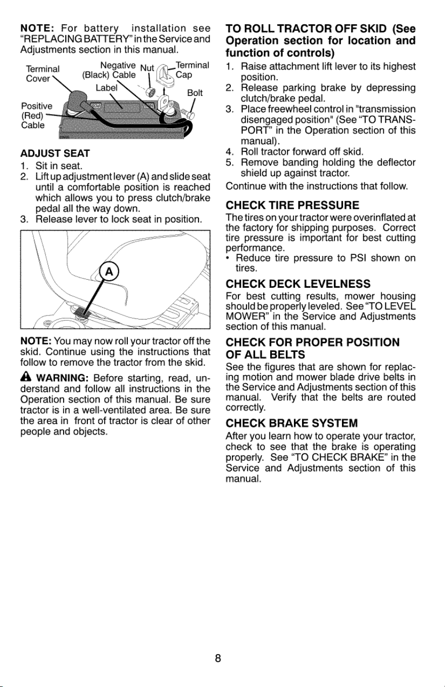
NOTE:
For
battery
installation
see
“REPLACING
BATTERY’
inthe
Service
and
Adjustments
section
in
this
manual.
Negative
jut
Terminal
(Black)
Cable
(See
A
Bolt
Terminal
Cover
Positive
(Red)
Cable
ADJUST
SEAT
1.
Sit
in
seat.
2.
Liftup
adjustmentlever
(A)
and
slide
seat
until
a
comfortable
position
is
reached
which
allows
you
to
press
clutch/brake
pedal
all
the
way
down.
3.
Release
lever
to
lock
seat
in
position.
NOTE:
You
may
now
roll
your
tractor
off
the
skid.
Continue
using
the
instructions
that
follow
to
remove
the
tractor
from
the
skid.
A
WARNING:
Before
starting,
read,
un-
derstand
and
follow
all
instructions
in
the
Operation
section
of
this
manual.
Be sure
tractor
is
in
a
well-ventilated
area.
Be sure
the
area
in
front
of
tractor
is
clear
of
other
people
and
objects.
TO
ROLL
TRACTOR
OFF
SKID
(See
Operation
section
for
location
and
function
of
controls)
1.
Raise
attachment
lift
lever
to
its
highest
position.
2.
Release
parking
brake
by
depressing
clutch/brake
pedal.
3.
Place
freewheel
control
in
“transmission
disengaged
position"
(See
“TO
TRANS-
PORT”
in
the
Operation
section
of
this
manual).
4.
Roll
tractor
forward
off
skid.
5.
Remove
banding
holding
the
deflector
shield
up
against
tractor.
Continue
with
the
instructions
that
follow.
CHECK
TIRE
PRESSURE
The
tires
on
your
tractor
were
overinflated
at
the
factory
for
shipping
purposes.
Correct
tire
pressure
is
important
for
best
cutting
performance.
*
Reduce
tire
pressure
to
PSI
shown
on
tires.
CHECK
DECK
LEVELNESS
For
best
cutting
results,
mower
housing
should
be
properly
leveled.
See
“TO
LEVEL
MOWER?’
in
the
Service
and
Adjustments
section
of
this
manual.
CHECK
FOR
PROPER
POSITION
OF
ALL
BELTS
See
the
figures
that
are
shown
for
replac-
ing
motion
and
mower
blade
drive
belts
in
the
Service
and
Adjustments
section
of
this
manual.
Verify
that
the
belts
are
routed
correctly.
CHECK
BRAKE
SYSTEM
After
you
learn
how
to
operate
your
tractor,
check
to
see
that
the
brake
is
operating
properly.
See
“TO
CHECK
BRAKE”
in
the
Service
and
Adjustments
section
of
this
manual.
/
CHECKLIST
Before
you
operate
your
new
tractor,
we
wish
to
assure
that
you
receive
the
best
performance
and
satisfaction
from
this
Quality
Product.
Please
review
the
following
checklist:
V
All
assembly
instructions
have
been
completed.
/
No
remaining
loose
parts
in
carton.
¥
Batteryis
properly
prepared
and
charged.
¥
Seat
is
adjusted
comfortably
and
tight-
ened
securely.
V
Alltires
are
properly
inflated.
(For
ship-
ping
purposes,
the
tires
were
overinflated
at
the
factory).
/
Ensure
mower
deck
is
properly
leveled
side-to-side/front-to-rear
for
best
cutting
results.
(Tires
must
be
properly
inflated
for
leveling).
v
Check
mower
and
drive
belts.
Ensure
they
are
routed
properly
around
pulleys
and
inside
all
belt
keepers.
¥
Checkwiring.
Seethatall
connections
are
stillsecure
and
wires
are
properlyclamped.
/
Before
driving
tractor,
be
sure
freewheel
controlis
in
“transmission
engaged”
posi-
tion
(see
“To
Transport’
in
the
Operation
section
of
this
manual).
While
learning
howto
use
your
tractor,
pay
ex-
tra
attention
to
the
following
important
items:
v
Engine
oil
is
at
proper
level.
/
Fueltankis
filled
with
fresh,
clean,
regular
unleaded
gasoline.
/¥
Become
familiar
with
all
controls,
their
location
and
function.
Operate
them
before
you
start
the
engine.
/
Ensure
brake
system
is
in
safe
operating
condition.
/
Ensure
Operator
Presence
System
and
Reverse
Operation
System
(ROS)
are
working
properly
(See
the
Operation
and
Maintenance
sections
in
this
manual).
V
Itisimportantto
purge
the
transmission
be-
fore
operating
your
tractor
for
the
firsttime.
Follow
proper
starting
and
transmission
purging
instructions
(See
“TO
START
EN-
GINE”
and
“PURGE
TRANSMISSION”
in
the
Operation
section
of
this
manual).
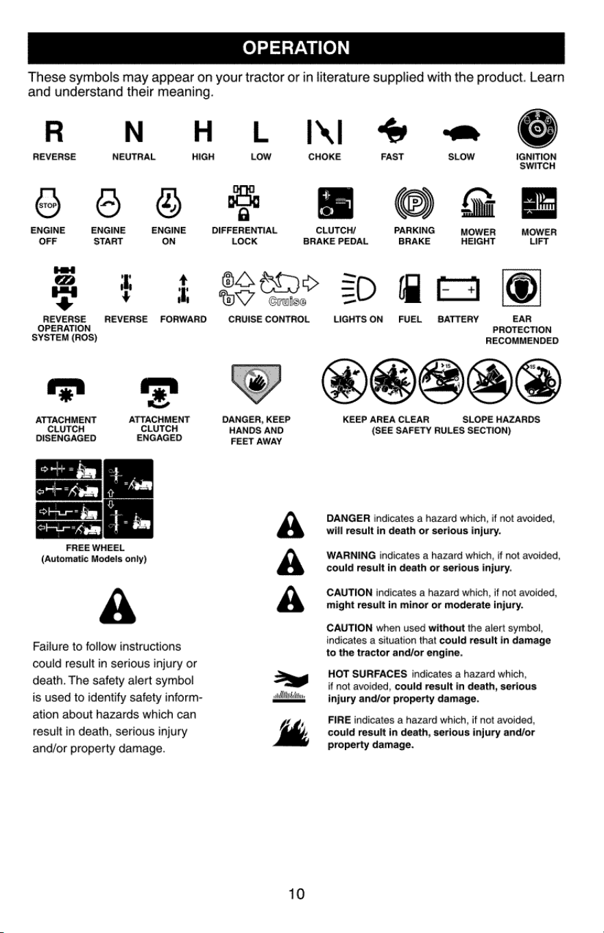
OPERATION
These
symbols
may
appear
on
your
tractor
or
in
literature
supplied
with
the
product.
Learn
and
understand
their
meaning.
R N
HLIEAI®@
REVERSE
NEUTRAL
HIGH
CHOKE
FAST
SLOW
IGNITION
SWITCH
foe
CC
oP
a
sll
ENGINE ENGINE ENGINE
DIFFERENTIAL
CLUTCH/
PARKING
MOWER
MOWER
OFF
START
ON
LOCK
BRAKE
PEDAL
BRAKE
HEIGHT
LIFT
HH
meee
“
¥
ho
mY
=
~s
Cruise
_
REVERSE REVERSE
FORWARD
CRUISE
CONTROL
LIGHTS
ON
FUEL
BATTERY
EAR
OPERATION
PROTECTION
SYSTEM
(ROS)
RECOMMENDED
*
we
)
ed
ATTACHMENT
ATTACHMENT
DANGER,
KEEP
KEEP
AREA
CLEAR
SLOPE
HAZARDS
CLUTCH CLUTCH
HANDS
AND
(SEE
SAFETY
RULES
SECTION)
DISENGAGED
ENGAGED
FEET
AWAY
DANGER
indicates
a
hazard
which,
if
not
avoided,
will
result
in
death
or
serious
injury.
FREE
WHEEL
(Automatic
Models
only)
A
WARNING
incicates
a
hazard
which,
if
not
avoided,
could
result
in
death
or
serious
injury.
CAUTION
indicates
a
hazard
which,
if
not
avoided,
might
result
in
minor
or
moderate
injury.
A
Failure
to
follow
instructions
could
result
in
serious
injury
or
death.
The
safety
alert
symbol
CAUTION
when
used
without
the
alert
symbol,
indicates
a
situation
that
could
result
in
damage
to
the
tractor
and/or
engine.
HOT
SURFACES
indicates
a
hazard
which,
if
not
avoided,
could
result
in
death,
serious
is
used
to
identify
safety
inform-
alli
injury
and/or
property
damage.
ation
about
hazards
which
can
kh
FIRE
indicates
a
hazard
which,
if
not
avoided,
result
in
death,
serious
injury
/
could
result
in
death,
serious
injury
and/or
and/or
property
damage.
property
damage.
10
KNOW
YOUR
TRACTOR
READ
THIS
OPERATOR'S
MANUAL
AND
SAFETY
RULES
BEFORE
OPERATING
YOUR
TRACTOR
Compare
the
illustrations
with
your
tractor
to
familiarize
yourself
with
the
locations
of
various
controls
and
adjustments.
Save
this
manual
for
future
reference.
Our
tractors
conform
to
the
applicable
safety
standards
of
the
American
National
Standards
Institute.
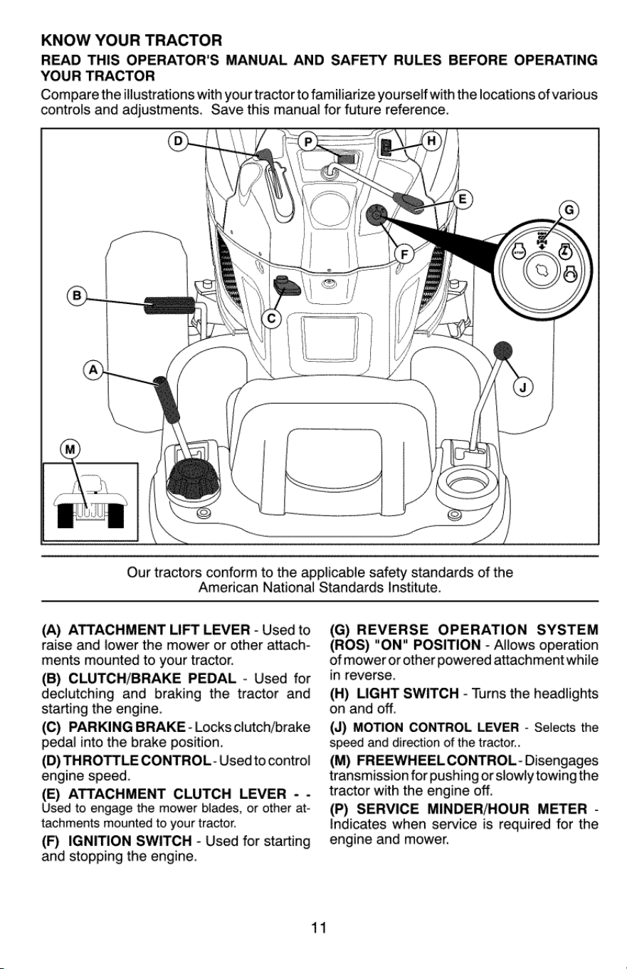
(A)
ATTACHMENT
LIFT
LEVER
-
Used
to
raise
and
lower
the
mower
or
other attach-
ments
mounted
to
your
tractor.
(B)
CLUTCH/BRAKE
PEDAL
-
Used
for
declutching
and braking
the
tractor
and
starting
the
engine.
(C)
PARKING
BRAKE
-
Locks
clutch/brake
pedal
into
the
brake
position.
(D)
THROTTLE
CONTROL-
Usedto
control
engine
speed.
(E)
ATTACHMENT
CLUTCH
LEVER
-
-
Used
to
engage
the
mower
blades,
or
other
at-
tachments
mounted
to
your
tractor.
(F)
IGNITION
SWITCH
-
Used
for
starting
and
stopping
the
engine.
(G)
REVERSE
OPERATION
SYSTEM
(ROS)
"ON"
POSITION
-
Allows
operation
of
mower
or
other
powered
attachment
while
in
reverse.
(H)
LIGHT
SWITCH
-
Turns
the
headlights
on
and
off.
(J)
MOTION
CONTROL
LEVER
-
Selects
the
speed
and
direction
of
the
tractor..
(M)
FREEWHEEL
CONTROL
-
Disengages
transmission
for
pushing
or
slowly
towing
the
tractor
with
the
engine
off.
(P)
SERVICE
MINDER/HOUR
METER
-
Indicates
when
service
is
required
for
the
engine
and
mower.
Rance
lace
aaa
ares
The
operation
of
any
tractor
can
result
in
foreign
objects
thrown
into
the
eyes,
which
can
result
in
severe
eye
damage.
Always
wear
safety
glasses
or
eye
shields
while
operating
your
tractor
or
performing
any
adjustments
or
repairs.
We
recommend
standard
safety
glasses
or
a
wide
vision
safety
mask
worn
over
spectacles.
HOW
TO
USE
YOUR
TRACTOR
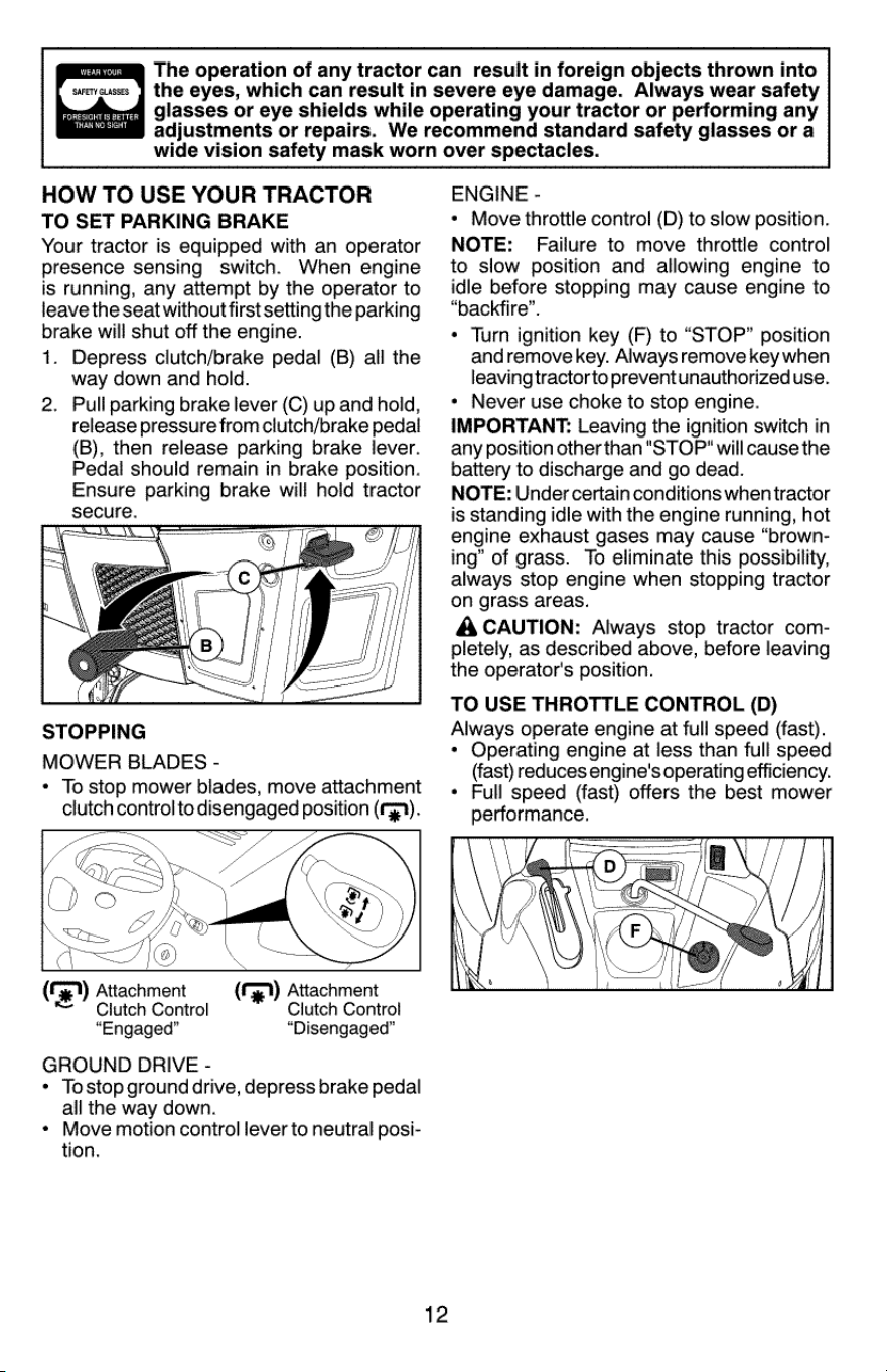
TO
SET
PARKING
BRAKE
Your
tractor
is
equipped
with
an
operator
presence
sensing
switch.
When
engine
is
running,
any
attempt
by
the
operator
to
leave
the
seat
without
first
setting
the
parking
brake
will
shut
off
the
engine.
1.
Depress
clutch/brake
pedal
(B)
all
the
way
down
and
hold.
Pull
parking brake
lever
(C)
up
and
hold,
release
pressure
from
clutch/brake
pedal
(B),
then
release
parking
brake
lever.
Pedal
should
remain
in
brake
position.
Ensure
parking
brake
will
hold
tractor
secure.
2.
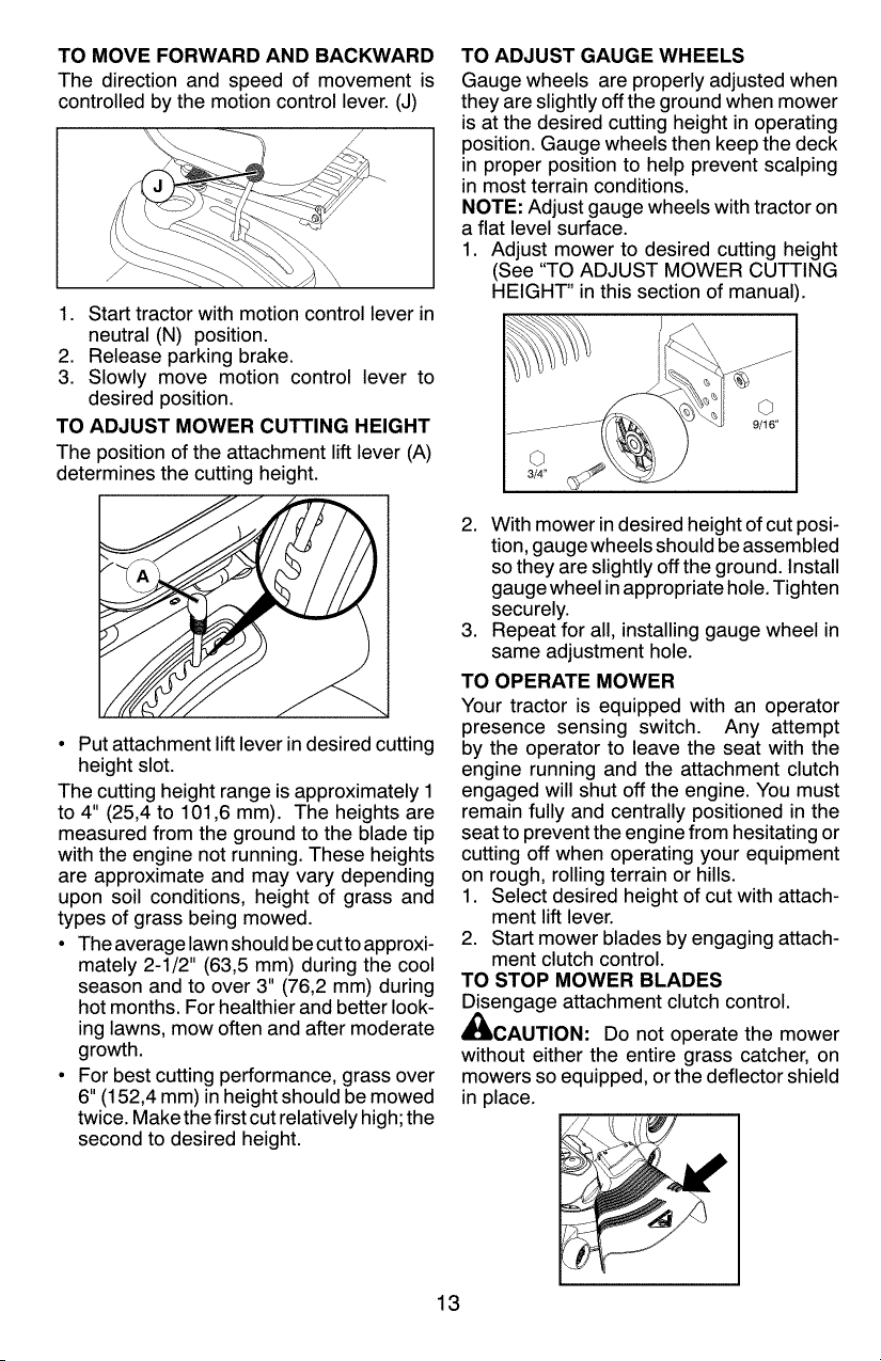
STOPPING
MOWER
BLADES
-
*
To
stop
mower
blades,
move
stone
clutch
control
to
disengaged
position
(fn
EQ
qr
Os
es
g
(|
Gf
@)
\
(fe)
Attachment
=
Clutch Control
“Engaged”
GROUND
DRIVE
-
*
Tostop ground
drive,
depress
brake
pedal
all
the
way
down.
*
Move
motion
control
lever
to
neutral
posi-
tion.
(Go)
)
Attachment
Clutch
Control
“Disengaged”
12
ENGINE
-
*
Move
throttle
control
(D)
to
slow
position.
NOTE:
Failure
to
move
throttle
control
to
slow
position
and
allowing
engine
to
idle
before
stopping
may
cause
engine
to
“backfire”.
Turn
ignition
key
(F)
to
“STOP”
position
and
remove
key.
Always
remove
key
when
leavingtractorto
prevent
unauthorized
use.
Never
use
choke
to
stop
engine.
IMPORTANT:
Leaving
the
ignition
switch
in
any
position
other
than
"STOP"
will
cause
the
battery
to
discharge
and
go
dead.
NOTE:
Under
certain
conditions
when
tractor
is
standing
idle
with
the
engine
running,
hot
engine
exhaust
gases
may
cause
“brown-
ing”
of
grass.
To
eliminate
this
possibility,
always
stop
engine
when
stopping
tractor
on
grass
areas.
A
CAUTION:
Always
stop
tractor
com-
pletely, as
described
above,
before
leaving
the
operator's
position.
TO
USE
THROTTLE
CONTROL
(D)
Always
operate
engine
at
full
speed
(fast).
*
Operating
engine
at
less
than
full
speed
(fast)
reduces
engine's
operating
efficiency.
«
Full
speed
(fast)
offers
the
best
mower
performance.
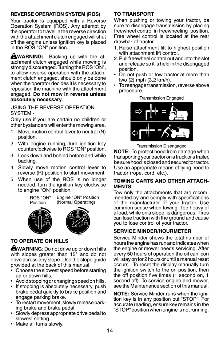
TO
MOVE
FORWARD
AND
BACKWARD
The
direction
and
speed
of
movement
is
controlled
by
the
motion
control
lever.
(J)
.
Start
tractor
with
motion
control
lever
in
neutral
(N)
position.
Release
parking
brake.
Slowly
move
motion
control
lever
to
desired
position.
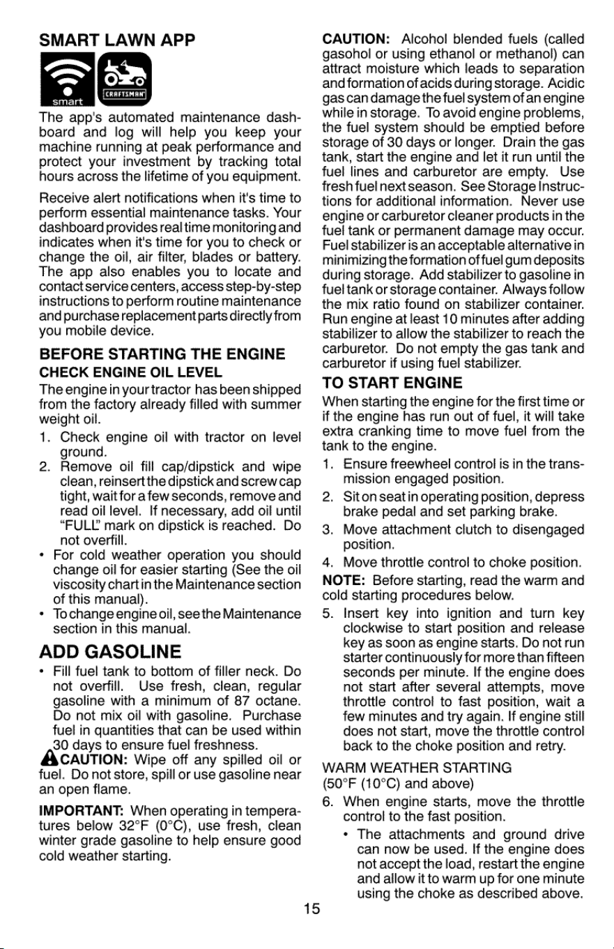
TO
ADJUST
MOWER
CUTTING
HEIGHT
The
position
of
the
attachment
lift
lever
(A)
determines
the
cutting height.
3.
*
Put
attachment
lift
lever
in
desired
cutting
height
slot.
The
cutting
height
range
is
approximately
1
to
4"
(25,4
to
101,6
mm). The
heights
are
measured
from
the
ground
to
the
blade
tip
with
the
engine
not
running.
These
heights
are
approximate
and
may
vary
depending
upon
soil
conditions,
height
of
grass
and
types
of
grass
being
mowed.
The
average
lawn
should
be
cutto
approxi-
mately
2-1/2"
(63,5
mm)
during
the
cool
season
and
to
over
3”
(76,2
mm)
during
hot
months.
For
healthier
and
better
look-
ing
lawns,
mow
often
and
after
moderate
growth.
For
best
cutting
performance,
grass
over
6"
(152,4
mm)
in
height
should
be
mowed
twice.
Make
the
first
cut
relatively
high;
the
second
to
desired
height.
13
TO
ADJUST
GAUGE
WHEELS
Gauge
wheels
are
properly
adjusted
when
they
are
slightly
off
the
ground
when
mower
is
at
the
desired
cutting
height
in
operating
position.
Gauge
wheels
then
keep
the
deck
in
proper
position
to
help
prevent
scalping
in
most
terrain
conditions.
NOTE:
Adjust
gauge
wheels
with
tractor
on
a flat
level
surface.
1.
Adjust
mower
to
desired
cutting
height
(See
“TO
ADJUST
MOWER
CUTTING
HEIGHT”
in
this
section
of
manual).
a
With
mower
in
desired
height
of
cut
posi-
tion,
gauge
wheels
should
be
assembled
so
they
are
slightly
off
the
ground.
Install
gauge
wheel
in
appropriate
hole.
Tighten
securely.
Repeat
for
all,
installing
gauge
wheel
in
same
adjustment
hole.
TO
OPERATE
MOWER
Your
tractor
is
equipped
with
an
operator
presence
sensing
switch.
Any
attempt
by
the
operator
to
leave
the
seat
with
the
engine
running
and
the
attachment
clutch
engaged
will
shut
off
the
engine.
You
must
remain
fully
and
centrally
positioned
in
the
seat
to
prevent
the
engine
from
hesitating
or
cutting
off
when
operating
your
equipment
on
rough,
rolling
terrain
or
hills.
1.
Select
desired
height
of
cut
with
attach-
ment
lift
lever.
2.
Start
mower
blades
by
engaging
attach-
ment
clutch
control.
TO
STOP
MOWER
BLADES
Disengage
attachment
clutch
control.
CAUTION:
Do
not
operate
the
mower
without
either
the entire
grass
catcher,
on
mowers
so
equipped,
or
the
deflector
shield
in
place.
3.
REVERSE
OPERATION
SYSTEM
(ROS)
Your
tractor
is
equipped
with
a
Reverse
Operation
System
(ROS).
Any
attempt
by
the
operator
to
travel
in
the
reverse
direction
with
the
attachment
clutch
engaged
will
shut
off
the
engine
unless
ignition
key
is
placed
in
the
ROS
"ON"
position.
AAWARNING:
=
Backing
up
with
the
at-
tachment
clutch
engaged
while
mowing
is
strongly
discouraged.
Turning
the
ROS
"ON",
to
allow
reverse
operation
with
the
attach-
ment
clutch
engaged,
should
only
be
done
when
the
operator
decides
itis
necessary
to
reposition
the
machine
with
the
attachment
engaged.
Do
not
mow
in
reverse
unless
absolutely
necessary.
USING
THE
REVERSE
OPERATION
SYSTEM
-
Only
use
if
you
are
certain
no
children
or
other
bystanders
will
enter
the
mowing
area.
1.
Move
motion
control
lever
to
neutral
(N)
position.
With
engine
running,
turn
ignition
key
counterclockwise
to
ROS
"ON"
position.
Look
down
and
behind
before
and
while
backing.
.
Slowly
move
motion
control
lever
to
reverse
(R)
position
to
start
movement.
When
use
of
the
ROS
is
no
longer
needed,
turn
the
ignition
key
clockwise
to
engine
"ON"
position.
ROS
"ON"
Engine
"ON"
Position
Position
(Normal
Operating)
2.
3.
TO
OPERATE
ON
HILLS
AWARNING:
Do
not
drive
up
or
down
hills
with
slopes
greater
than
15°
and
do
not
drive
across
any
slope.
Use
the
slope
guide
provided
at
the
back
of
this
manual.
*
Choose
the
slowest
speed
before
starting
up
or
down
hills.
Avoid stopping
or
changing
speed
on
hills.
If
stopping
is
absolutely
necessary,
push
brake
pedal
quickly
to
brake
position
and
engage
parking
brake.
To
restart
movement,
slowly
release
park-
ing
brake
and
brake
pedal.
Slowly
depress
appropriate
drive
pedal
to
slowest
setting.
Make
all
turns
slowly.
14
TO
TRANSPORT
When
pushing
or
towing
your
tractor,
be
sure
to
disengage
transmission
by
placing
freewheel
control
in
freewheeling
position.
Free
wheel
control
is
located
at
the
rear
drawbar
of
tractor.
1.
Raise
attachment
lift
to
highest
position
with
attachment
lift
control.
2.
Pull
freewheel
control
out
and
into
the
slot
and
release
so
itis
held
in
the
disengaged
position.
¢
Do
not
push
or
tow
tractor
at
more
than
two
(2)
mph
(3,2
km/h).
*
Toreengage
transmission,
reverse
above
procedure.
Transmission
Engaged
Transmission
Disengaged
NOTE:
To
protect
hood
from
damage
when
transporting
your
tractor
on
atruck
ora
trailer,
be
sure
hoodis
closed
and
secured
to
tractor.
Use
an
appropriate
means
of
tying
hood
to
tractor
(rope,
cord,
etc.).
TOWING
CARTS
AND
OTHER
ATTACH-
MENTS
Tow
only
the
attachments
that
are
recom-
mended
by
and
comply
with
specifications
of
the
manufacturer
of
your
tractor.
Use
common
sense
when
towing.
Too
heavy
of
aload,
while
ona
slope,
is
dangerous.
Tires
can
lose
traction
with
the
ground
and
cause
you
to
lose
control
of
your
tractor.
SERVICE
MINDER/HOURMETER
Service
Minder
shows
the
total
number
of
hours
the
engine
has
run
and
indicates
when
the
engine
or
mower
needs
servicing.
After
every
50
hours
of
operation
the
oil
can
icon
will
stay
on
for
2
hours
or
untila
manual
reset
occurs.
To
reset
the
display
manually
turn
the
ignition
switch
to
the
on
position,
then
the
off
position
five
times
(1
second
on,
1
second
off).
To
service
engine
and
mower,
see
the
Maintenance
section
of
this
manual.
NOTE:
Service
Minder
runs
when
the
igni-
tion
key
is
in
any
position
but
“STOP”.
For
accurate
reading,
ensure
key
remains
in
the
“STOP”
position
when
engine
is
notrunning.
—,
LAWN
APP
ie
t
[CRAFTSMAN]
sara
The
app's
automated
maintenance
dash-
board
and
log
will
help
you
keep
your
machine
running
at
peak
performance
and
protect
your
investment
by
tracking
total
hours
across
the
lifetime
of
you
equipment.
Receive
alert
notifications
when
it’s
time
to
perform
essential
maintenance
tasks.
Your
dashboard
provides
realtime
monitoring
and
indicates
when
it's
time
for
you
to
check
or
change
the
oil,
air
filter,
blades
or
battery.
The
app
also
enables
you
to
locate
and
contact
service
centers,
access
step-by-step
instructions
to
perform
routine
maintenance
and
purchase
replacement
parts
directly
from
you
mobile
device.
BEFORE
STARTING
THE
ENGINE
CHECK
ENGINE
OIL
LEVEL
The
engine
in
yourtractor
has
been
shipped
from
the
factory
already
filled
with
summer
weight
oil.
1.
Check
engine
oil
with
tractor
on
level
ground.
Remove
oil
fill
cap/dipstick
and
wipe
clean,
reinsert
the
dipstick
and
screw
cap
tight,
wait
for
a
few
seconds,
remove
and
read
oil
level.
If
necessary,
add
oil
until
“FULL
mark
on
dipstick
is
reached.
Do
not
overfill.
For cold
weather
operation
you
should
change
oil
for
easier
starting
(See
the
oil
viscosity
chartin
the
Maintenance
section
of
this
manual).
To
change
engine
oil,
see
the
Maintenance
section
in
this
manual.
ADD
GASOLINE
*
Fill
fuel
tank
to
bottom
of
filler
neck.
Do
not
overfill.
Use
fresh,
clean,
regular
gasoline
with
a
minimum
of
87
octane.
Do
not
mix
oil
with
gasoline.
Purchase
fuel
in
quantities
that
can
be
used
within
30
days
to
ensure
fuel
freshness.
ACAUTION:
Wipe
off
any
spilled
oil
or
fuel.
Do
not
store,
spill
or
use
gasoline
near
an
open
flame.
IMPORTANT:
When
operating
in
tempera-
tures
below
32°F
(0°C),
use
fresh,
clean
winter
grade
gasoline
to
help
ensure good
cold
weather
starting.
2.
15
CAUTION:
Alcohol
blended
fuels
(called
gasohol
or
using
ethanol
or
methanol)
can
attract
moisture
which
leads
to
separation
and
formation
of
acids
during
storage.
Acidic
gas can
damage
the
fuel
system
of
an
engine
while
in
storage.
To
avoid
engine
problems,
the
fuel
system
should
be
emptied
before
storage
of
30
days
or
longer.
Drain
the
gas
tank,
start
the
engine
and
let
it
run
until
the
fuel
lines
and
carburetor
are
empty.
Use
fresh
fuel
next
season.
See
Storage
Instruc-
tions
for
additional
information.
Never
use
engine
or
carburetor
cleaner
products
in
the
fuel
tank
or
permanent
damage
may
occur.
Fuel
stabilizer
is
an
acceptable
alternative
in
minimizing
the
formation
of
fuel
gum
deposits
during
storage.
Add
stabilizer
to
gasoline
in
fuel
tank
or
storage
container.
Always
follow
the
mix
ratio
found
on
stabilizer
container.
Run
engine
at
least
10
minutes
after
adding
stabilizer
to
allow
the
stabilizer
to
reach
the
carburetor.
Do
not
empty
the
gas
tank
and
carburetor
if
using
fuel
stabilizer.
TO
START
ENGINE
When
starting
the
engine
for
the
first
time
or
if
the
engine
has
run
out
of
fuel,
it
will
take
extra
cranking
time
to
move
fuel
from
the
tank
to
the
engine.
1.
Ensure
freewheel
control
is
in
the
trans-
mission
engaged
position.
Siton
seat
in
operating
position,
depress
brake
pedal
and
set
parking
brake.
Move
attachment
clutch
to
disengaged
position.
4.
Move
throttle
contro!
to
choke
position.
NOTE:
Before
starting,
read
the
warm
and
cold
starting
procedures
below.
5.
Insert
key
into
ignition
and
turn
key
clockwise
to
start
position
and
release
key
as
soon
as
engine
starts.
Do
not run
starter
continuously
for
more
than
fifteen
seconds
per
minute.
If
the
engine
does
not
start
after
several
attempts,
move
throttle
control
to
fast
position,
wait
a
few
minutes
and
try
again.
If
engine
still
does
not
start,
move
the
throttle
control
back
to
the
choke
position
and
retry.
WARM
WEATHER
STARTING
(50°F
(10°C)
and
above)
6.
When
engine
starts,
move
the
throttle
control
to
the
fast
position.
*
The
attachments
and
ground
drive
can
now
be
used.
If
the
engine
does
not
accept
the
load,
restart
the
engine
and
allow
it
to
warm
up
for
one
minute
using
the
choke
as
described
above.
2.
3.
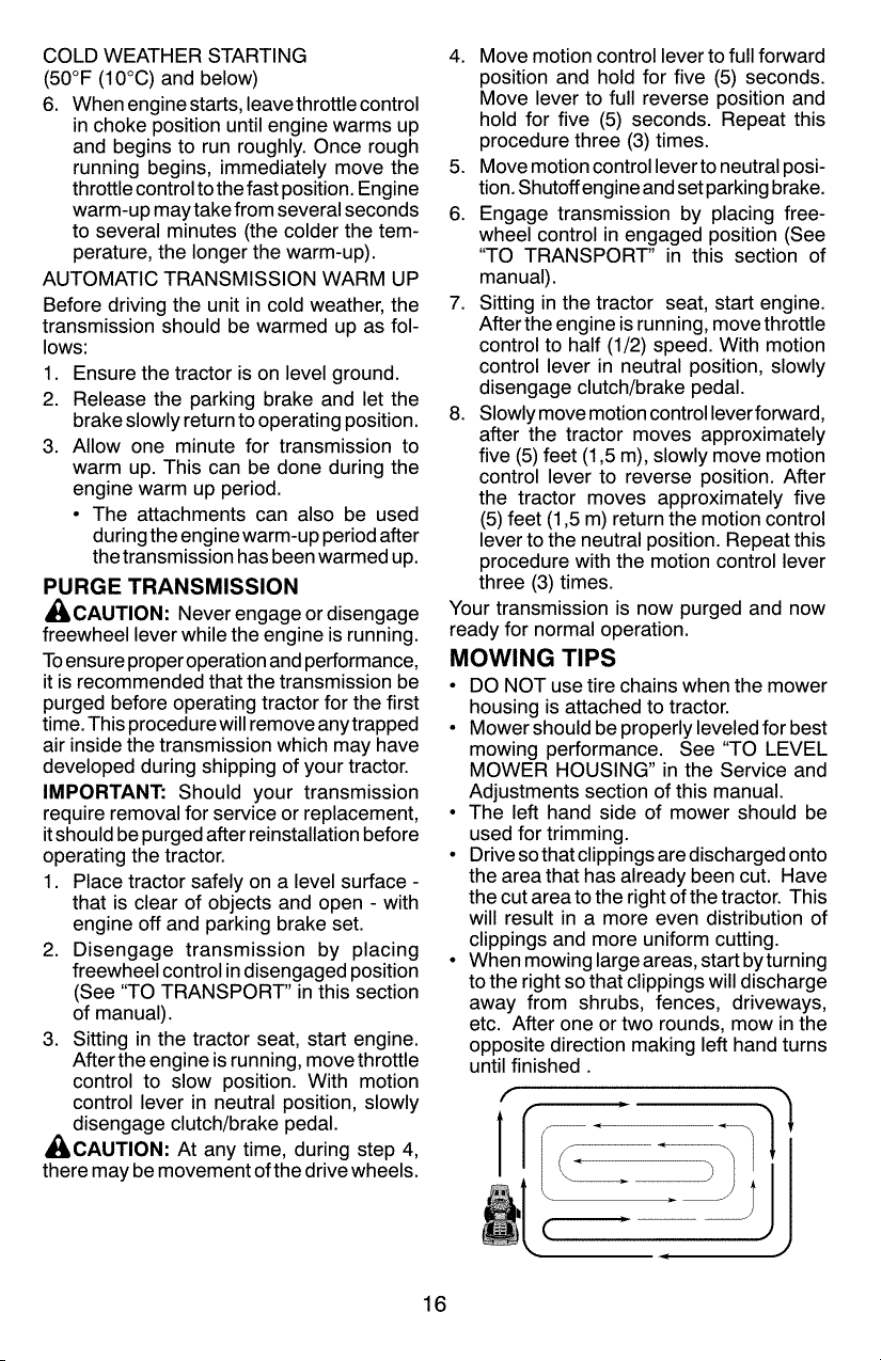
COLD
WEATHER
STARTING
(50°F
(10°C)
and
below)
6.
Whenengine
starts,
leave
throttle
control
in
choke
position
until
engine
warms
up
and
begins
to
run
roughly.
Once
rough
running
begins,
immediately
move
the
throttle
control
to
the
fast
position.
Engine
warm-up
may
take
from
several
seconds
to
several
minutes
(the
colder
the
tem-
perature,
the
longer
the
warm-up).
AUTOMATIC
TRANSMISSION
WARM
UP
Before
driving
the
unit
in
cold
weather,
the
transmission
should
be
warmed
up
as
fol-
lows:
1.
Ensure
the
tractor
is
on
level
ground.
2.
Release
the
parking
brake
and
let
the
brake
slowly
return
to
operating
position.
Allow one
minute
for
transmission
to
warm
up.
This
can
be
done
during
the
engine
warm
up
period.
*
The
attachments
can
also
be
used
during
the
engine
warm-up
period
after
the
transmission
has
been
warmed
up.
PURGE
TRANSMISSION
ACAUTION:
Never
engage
or
disengage
freewheel
lever
while
the
engine
is
running.
To
ensure
proper
operation
and
performance,
it
is
recommended
that
the
transmission
be
purged
before
operating
tractor
for
the
first
time.
This
procedure
will
remove
any
trapped
air
inside
the
transmission
which
may
have
developed
during
shipping
of
your
tractor.
IMPORTANT:
Should
your
transmission
require
removal
for
service
or
replacement,
itshould
be
purged
after
reinstallation
before
operating
the
tractor.
1.
Place
tractor
safely
on
a
level
surface
-
that
is
clear
of
objects
and
open
-
with
engine
off
and
parking
brake
set.
Disengage
transmission
by
placing
freewheel
control
in
disengaged
position
(See
“TO
TRANSPORT?
in
this
section
of
manual).
Sitting
in
the
tractor
seat,
start
engine.
After
the
engine
is
running,
move
throttle
control
to
slow
position.
With
motion
control
lever
in
neutral
position,
slowly
disengage
clutch/brake
pedal.
ACAUTION:
At
any
time,
during
step
4,
there
may
be
movement
of
the
drive
wheels.
3.
16
Move
motion
control
lever
to
full
forward
position
and
hold
for
five
(5)
seconds.
Move
lever
to
full
reverse
position
and
hold
for
five
(6)
seconds.
Repeat
this
procedure
three
(3)
times.
Move
motion
control
lever
to
neutral
posi-
tion.
Shutoff
engine
and
set
parking
brake.
Engage
transmission
by
placing
free-
wheel
control
in
engaged
position
(See
“TO
TRANSPORT”
in
this
section
of
manual).
Sitting
in
the
tractor
seat,
start
engine.
After
the
engine
is
running,
move
throttle
control
to
half
(1/2)
speed.
With
motion
control
lever
in
neutral
position,
slowly
disengage
clutch/brake
pedal.
Slowly
move
motion
controllever
forward,
after
the
tractor
moves
approximately
five
(5)
feet
(1,5
m),
slowly
move
motion
control
lever
to
reverse
position.
After
the
tractor
moves
approximately
five
(5)
feet
(1,5
m)
return
the
motion
control
lever
to
the
neutral
position.
Repeat
this
procedure
with
the
motion
control
lever
three
(3)
times.
Your
transmission
is
now
purged
and
now
ready
for
normal
operation.
MOWING
TIPS
*
DO
NOT
use
tire
chains
when
the
mower
housing
is
attached
to
tractor.
Mower
should
be
properly
leveled
for
best
mowing
performance.
See
“TO
LEVEL
MOWER
HOUSING?’
in
the
Service
and
Adjustments
section
of
this
manual.
The
left
hand
side
of
mower
should
be
used
for
trimming.
Drive
so
that
clippings
are
discharged
onto
the
area
that
has
already
been
cut.
Have
the
cut
area
to
the
right
of
the
tractor.
This
will
result
in
a
more
even
distribution
of
clippings
and
more
uniform
cutting.
When
mowing
large
areas,
start
by
turning
to
the
right
so
that
clippings
will
discharge
away
from
shrubs,
fences,
driveways,
etc.
After
one
or
two
rounds,
mow
in
the
opposite
direction
making
left
hand
turns
until
finished
.

If
grass
is
extremely
tall,
it
should
be
mowed
twice
to
reduce
load
and
possible
fire
hazard
from
dried
clippings.
Make
first
cut
relatively
high;
the
second
to
the
desired
height.
Do
not
mow
grass
when
it
is
wet.
Wet
grass
will
plug
mower
and
leave
undesir-
able
clumps.
Allow grass
to
dry
before
mowing.
Always
operate
engine
at
full
throttle
when
mowing
to
assure
better
mow-
ing
performance
and
proper
discharge
of
material.
Regulate
ground
speed
by
selecting
a
low
enough
gear
to
give
the
mower
cutting
performance
as
well
as
the
quality
of
cut
desired.
When
operating
attachments,
select
a
ground
speed
that
will
suit
the
terrain
and
give
best
performance
of
the
attachment
being
used.
17
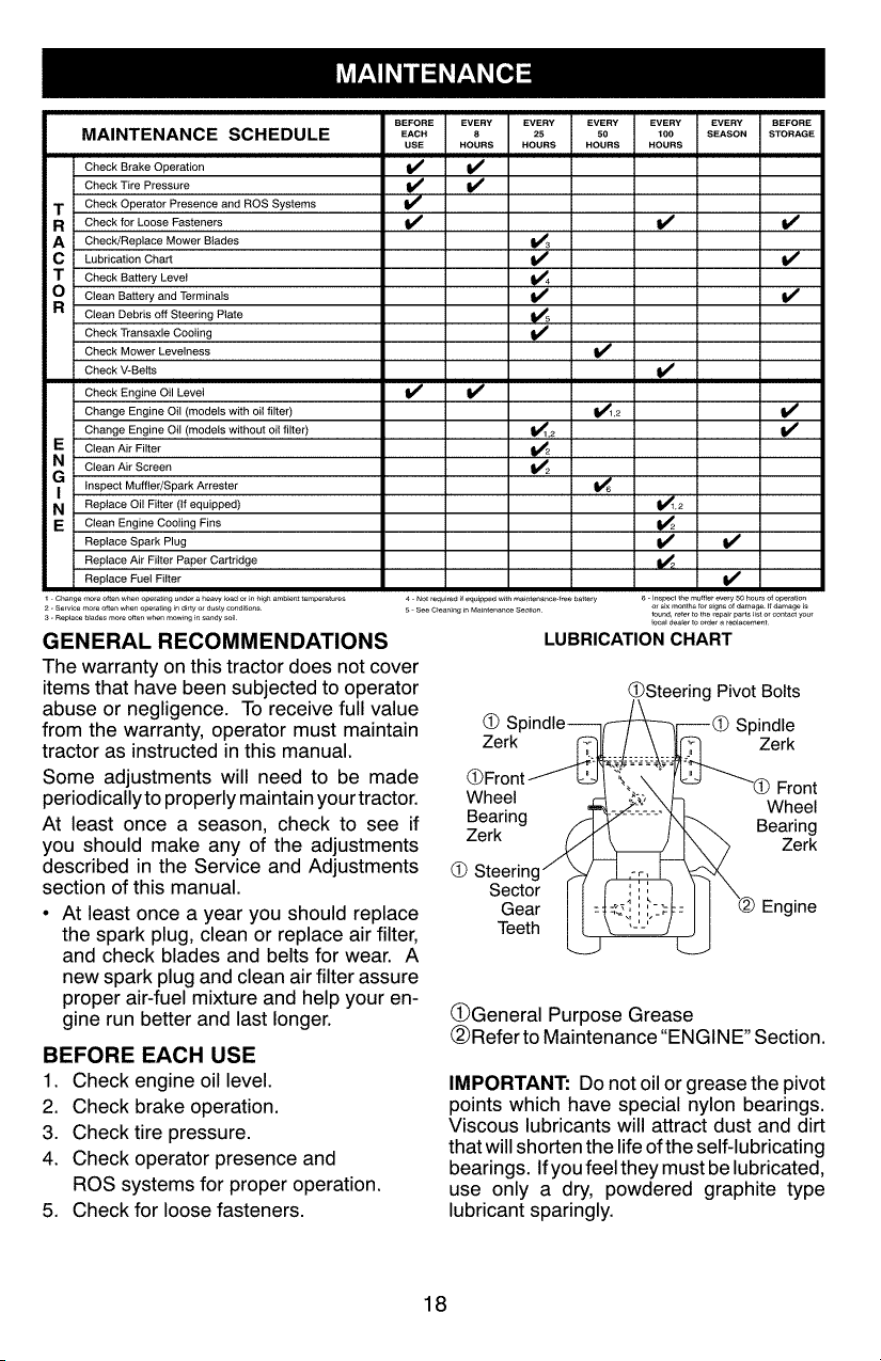
MAINTENANCE
BEFORE
MAINTENANCE
SCHEDULE
EACH
USE
Check
Brake
Check
Tire
Pressure
Check
Presence
and
ROS
Check
for
Loose
Fasteners
Mower
Blades
Lubrication
Chart
Check
Level
Clean
and
Terminals
Clean
Debris
off
Plate
Check
Transaxle
DOHOPI
Check
Mower
Levelness
Check
V-Belis
Check
Oil
Level
Ol
Ol
Clean
Air
Filter
Clean
Air
Screen
with
olf
without
off
Arrester
Oil
Filter
Mma~O 2M
Fins
Air
Filter
Fuel
Filter
1.
Ghange
more
often
when
operating
under
a
heavy
toad
or
in
high
ambient
temperatures,
2+
Service
more
often
when
operating
in
dirty
or
dusty
conditions,
2+
Replace
blades
more
often
when
mowing
in
sandy
soil
GENERAL
RECOMMENDATIONS
The
warranty
on
this
tractor
does
not
cover
items
that
have
been
subjected
to
operator
abuse
or
negligence.
To
receive
full
value
from
the
warranty,
operator
must
maintain
tractor
as
instructed
in
this
manual.
Some
adjustments
will
need
to
be
made
periodically
to
properly
maintain
your
tractor.
At
least
once
a
season,
check
to
see
if
you
should
make
any
of
the
adjustments
described
in
the
Service
and
Adjustments
section
of
this
manual.
At
least
once
a
year
you
should
replace
the
spark
plug,
clean
or
replace
air
filter,
and
check
blades
and
belts
for
wear.
A
new
spark
plug
and
clean
air
filter
assure
proper
air-fuel
mixture
and
help
your
en-
gine
run
better
and
last
longer.
BEFORE
EACH
USE
1.
Check
engine
oil
level.
Check
brake
operation.
Check
tire
pressure.
Check
operator
presence
and
ROS
systems
for
proper
operation.
Check
for
loose
fasteners.
2.
3.
4
4-
Not
requited
if
equipped
with
maintenance-tree
battery
5-
See Cleaning
in
Maintenance
Section
18
EVERY
8
HOURS
EVERY
25
HOURS:
EVERY
50
HOURS
EVERY
100
HOURS
EVERY
SEASON
BEFORE
STORAGE
6
-
Inspect
the
muffler
every
50
hours
of
operation
or six
months
for
signs
of
damage.
if
damage
is
tound,
refer
to
the
repair parts
list
of
contact
your
local
dealer
to
order
a
replacement,
LUBRICATION
CHART
@Steering
Pivot
Bolts
®
Spindle
®
Spindle
Zerk
Zerk
@Front
Wheel
®
Front
my
PN
en
Wheel
Bearing
Bearing
Zerk Zerk
®
Steering
Sector
Gear
@®
Engine
Teeth
@General
Purpose
Grease
@Refer
to
Maintenance
“ENGINE”
Section.
IMPORTANT:
Do
not
oil
or
grease
the
pivot
points
which
have
special
nylon
bearings.
Viscous
lubricants
will
attract
dust
and
dirt
that
will
shorten
the
life
of
the
self-lubricating
bearings.
If
you
feel
they
must
be
lubricated,
use
only
a
dry,
powdered
graphite
type
lubricant
sparingly.

TRACTOR
Always
observe
safety
rules
when
perform-
ing
any
maintenance.
BRAKE
OPERATION
If
tractor
requires
more
than
5
feet
(1,5
m)
to
stop
at
highest
speed
in
highest
gear
on
a
level,
dry
concrete
or
paved
surface,
then
brake
must
be
serviced.
(See
“TO
CHECK
BRAKE”
in
the
Service
and
Adjustments
section
of
this
manual).
TIRES
Maintain
proper
air
pressure
in
all
tires
(See
the
side
of
tires
for
proper
PSI.)
Keep
tires
free
of
gasoline,
oil,
or
insect
control
chemicals
which
can
harm
rubber.
Avoid
stumps,
stones,
deep
ruts,
sharp
objects
and
other
hazards
that
may
cause
tire
damage.
NOTE:
To
seal
tire
punctures
and
prevent
flat
tires
due
to
slow
leaks,
tire
sealant
may
be
purchased
from
your
local
parts
dealer.
Tire
sealant
also
prevents
tire
dry
rot
and
corrosion.
OPERATOR
PRESENCE
SYSTEM
AND
REVERSE
OPERATION
SYSTEM
(ROS)
Be
sure
operator
presence
and
reverse
operation
systems
are
working
properly.
if
your
tractor
does
not
function
as
described,
repair
the
problem
immediately.
*
The
engine
should
not
start
unless
the
brake
pedal
is
fully
depressed,
and
the
attachment
clutch
control
is
in
the
disen-
gaged
position.
CHECK
OPERATOR
PRESENCE
SYSTEM
When
the
engine
is
running,
any
attempt
by
the
operator
to
leave
the
seat
without
first
setting
the
parking
brake
should
shut
off
the
engine.
When
the
engine
is
running
and
the
at-
tachment
clutch
is
engaged,
any
attempt
by
the
operator
to
leave
the
seat
should
shut
off
the
engine.
The
attachment
clutch
should
never
oper-
ate
unless
the
operator
is in
the
seat.
CHECK
REVERSE
OPERATION
(ROS)
SYSTEM
When
the
engine
is
running
with
the
ignition
switch
in
the
engine
“ON”
position
and
the
attachment
clutch
engaged,
any
attempt
by
the
operator
to
drive
in
reverse
should
shut
off
the
engine.
When
the
engine
is
running
with
the
ignition
switch
in
the
ROS
"ON"
position
and
the
attachment
clutch
engaged,
any
attempt
by
the
operator
to
drive
in
reverse
should
NOT
shut
off
the
engine.
19
NS)
Ros
"On"
Engine
"On"
Position
Position
(Normal
Operating)
BLADE
CARE
For
best
results
mower
blades
must
be
sharp.
Replace
worn,
bent
or
damaged
blades.
ACAUTION:
Use
only
areplacementblade
approved
by
the
manufacturer
of
your
tractor.
Using
a
blade
not
approved
by
the
manu-
facturer
of
your
tractor
is
hazardous,
could
damage
your
tractor
and
void
your
warranty.
BLADE
REMOVAL
1.
Raise
mower
to
highest
position
to
allow
access
to
blades.
NOTE:
Protect
your
hands
with
gloves
and/
or
wrap
biade
with
heavy
cloth.
2.
Remove
blade
bolt
by
turning
counter-
clockwise.
Install
new
blade
with
stamped
"GRASS
SIDE"
facing
the
ground.
IMPORTANT:
To
ensure
proper
assembly,
center
hole
in
blade
must
align
with
star
on
mandrel
assembly.
4.
Install
and
tighten
blade
bolt
securely
(45-55
Ft.
Lbs./62-75
Nm).
IMPORTANT:
Special
blade
bolt
is
heat
treated.
3.
Star
Center
Hole
Blade
Bolt
(Specia)
Assembly
BATTERY
Your
tractor
has
a
battery
charging
system
which
is
sufficient
for
normal
use.
However,
periodic
charging
of
the
battery
with
an
au-
tomotive
charger
will
extend
its
life.
*
Keep
battery
and
terminals
clean.
*
Keep
battery
bolts
tight.
«
Keep
small
vent
holes
open.
*
Recharge
at
6-10
amperes
for
1
hour.
NOTE:
The
original
equipment
battery
on
your
tractor
is
maintenance
free.
Do
not
attempt
to
open
or
remove
caps
or
covers.
Adding
or
checking
level
of
electrolyte
is
not
necessary.
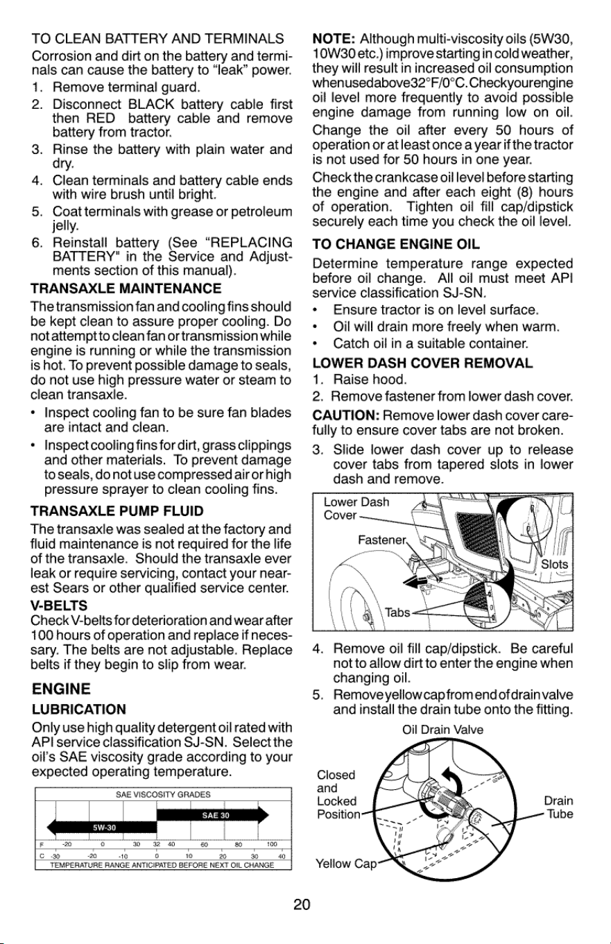
TO
CLEAN
BATTERY
AND
TERMINALS
Corrosion
and
dirt
on
the
battery
and
termi-
nals
can
cause
the
baitery
to
“leak”
power.
1.
Remove
terminal
guard.
2.
Disconnect
BLACK
battery
cable
first
then
RED
battery
cable
and
remove
battery
from
tractor.
Rinse
the
battery
with
plain
water
and
ry.
Clean
terminals
and
battery
cable
ends
with
wire
brush
until
bright.
Coat
terminals
with
grease
or
petroleum
jelly.
Reinstall
battery
(See
“REPLACING
BATTERY"
in
the
Service
and
Adjust-
ments
section
of
this
manual).
TRANSAXLE
MAINTENANCE
The
transmission
fan
and
cooling
fins
should
be
kept
clean
to
assure
proper
cooling.
Do
not
attemptto
clean
fan
or
transmission
while
engine
is
running
or
while
the
transmission
is
hot.
To
prevent
possible
damage
to
seals,
do
not
use
high
pressure
water
or
steam
to
clean
transaxle.
Inspect
cooling
fan
to
be
sure
fan
blades
are
intact
and
clean.
Inspect
cooling
fins
for
dirt,
grass
clippings
and
other
materials.
To
prevent
damage
to
seals,
do
notuse
compressed
air
or
high
pressure
sprayer
to
clean cooling
fins.
TRANSAXLE
PUMP
FLUID
The
transaxle
was
sealed
at
the
factory
and
fluid
maintenance
is
not
required
for
the
life
of
the
transaxle.
Should
the
transaxle
ever
leak
or
require
servicing,
contact
your
near-
est
Sears
or
other
qualified
service
center.
V-BELTS
Check
V-belts
for
deterioration
and
wear
after
100
hours
of
operation
and
replace
if
neces-
sary.
The
belts
are
not
adjustable.
Replace
belts
if
they
begin
to
slip
from
wear.
ENGINE
LUBRICATION
Only
use
high
quality
detergent
oil
rated
with
API
service
classification
SJ-SN.
Select
the
oil's
SAE
viscosity
grade
according
to
your
expected
operating
temperature.
SAE
VISCOSITY
GRADES
20
NOTE:
Although
multi-viscosity
oils
(6W30,
10W30
etc.)
improve
starting
in
cold
weather,
they
will
result
in
increased
oil
consumption
whenusedabove32°F/0°C.
Checkyourengine
oil
level
more
frequently
to
avoid
possible
engine
damage
from
running
low
on
oil.
Change
the
oil
after
every
50
hours
of
operation
or
atleast
once
a
year
if
the
tractor
is
not
used
for
50
hours
in
one
year.
Check
the
crankcase
oil
level
before
starting
the
engine
and
after
each
eight
(8)
hours
of
operation.
Tighten
oil
fill
cap/dipstick
securely
each
time
you
check
the
oil
level.
TO
CHANGE
ENGINE
OIL
Determine
temperature
range
expected
before
oil
change.
All
oil
must
meet
API
service
classification
SJ-SN.
Ensure
tractor
is
on
level
surface.
Oil
will
drain
more
freely
when
warm.
Catch
oil
in
a
suitable
container.
LOWER
DASH
COVER
REMOVAL
1.
Raise
hood.
2.
Remove
fastener
from
lower
dash
cover.
CAUTION:
Remove
lower
dash
cover
care-
fully
to
ensure
cover
tabs
are
not
broken.
3.
Slide
lower
dash
cover
up
to
release
cover
tabs
from
tapered
slots
in
lower
dash
and
remove.
4.
Remove
oil
fill
cap/dipstick.
Be
careful
not
to
allow
dirt
to
enter
the
engine
when
changing
oil.
Remove
yellowcapfrom
end
ofdrainvalve
and
install
the
drain
tube
onto
the
fitting.
Oil
Drain
Valve
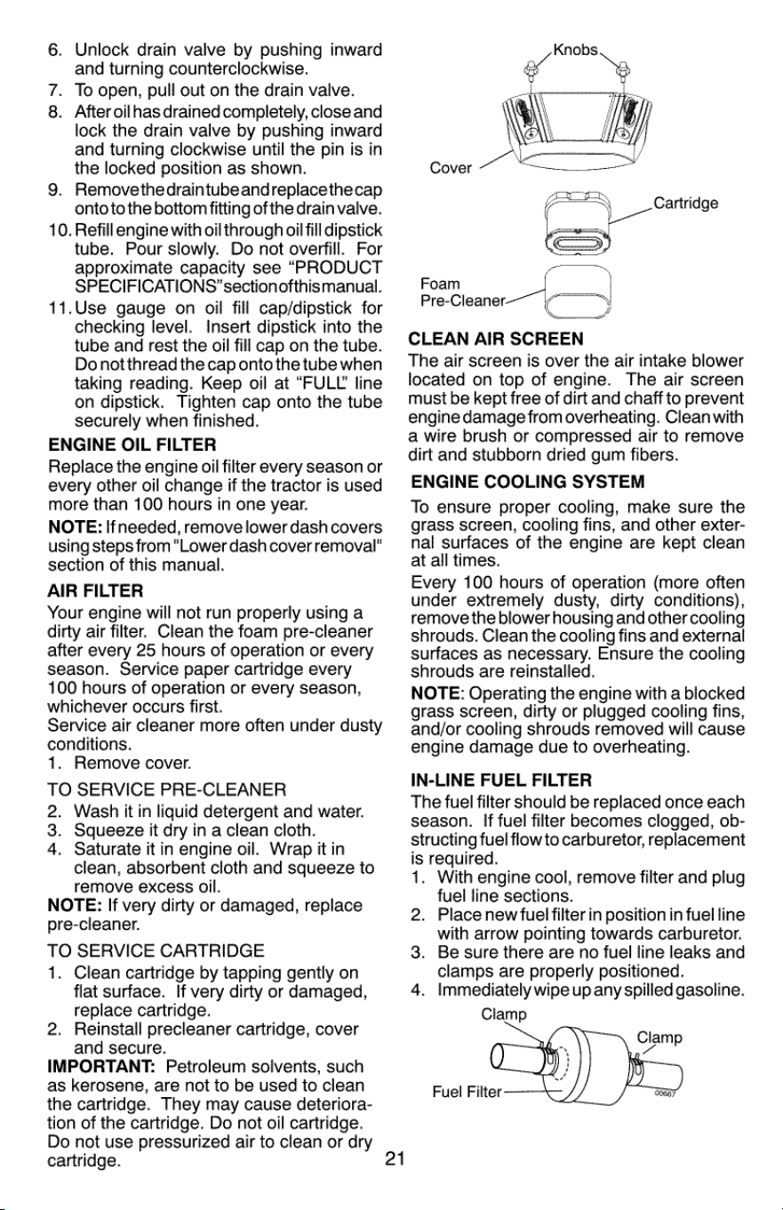
6.
Unlock
drain
valve
by
pushing
inward
and
turning
counterclockwise.
7.
To
open,
pull
out
on
the
drain
valve.
8.
After
oilhas
drained
completely,
close
and
lock
the
drain
valve
by
pushing
inward
and
turning
clockwise
until
the
pin
is
in
the
locked
position
as
shown.
9.
Removethedraintubeandreplacethecap
onto
to
the
bottom
fitting
of
the
drain
valve.
10.
Refill
engine
with
oil
through
oil
fill
dipstick
tube.
Pour
slowly.
Do
not
overfill.
For
approximate
capacity
see
“PRODUCT
SPECIFICATIONS’
sectionofthismanual.
11.Use
gauge
on
oil
fill
cap/dipstick
for
checking
level.
Insert
dipstick
into
the
tube
and
rest
the
oil
fill
cap
on
the
tube.
Do
notthread
the
cap
onto
the
tube
when
taking
reading.
Keep
oil
at
“FULL
line
on
dipstick.
Tighten
cap
onto
the
tube
securely
when
finished.
ENGINE
OIL
FILTER
Replace
the
engine
oil
filter
every
season
or
every
other
oil
change
if
the
tractor
is
used
more
than
100
hours
in
one
year.
NOTE:
If
needed,
remove
lower
dash
covers
using
steps
from
"Lower
dash
cover
removal"
section
of
this
manual.
AIR
FILTER
Your
engine
will
not run
properly
using
a
dirty
air
filter.
Clean
the
foam
pre-cleaner
after
every
25
hours
of
operation
or
every
season.
Service
paper
cartridge
every
100
hours
of
operation
or
every
season,
whichever
occurs
first.
Service
air
cleaner
more
often
under
dusty
conditions.
1.
Remove
cover.
TO
SERVICE
PRE-CLEANER
2.
Wash
it
in
liquid
detergent
and
water.
3.
Squeeze
it
dry
in
a
clean
cloth.
4.
Saturate
it
in
engine
oil.
Wrap
it
in
clean,
absorbent
cloth
and
squeeze
to
remove
excess
oil.
NOTE:
If
very
dirty
or
damaged,
replace
pre-cleaner.
TO
SERVICE
CARTRIDGE
1.
Clean
cartridge
by
tapping
gently
on
flat
surface.
If
very
dirty
or
damaged,
replace
cartridge.
2.
Reinstall
precleaner
cartridge,
cover
and
secure.
IMPORTANT:
Petroleum
solvents,
such
as
kerosene,
are
not
to
be
used
to
clean
the
cartridge.
They
may
cause
deteriora-
tion
of
the
cartridge.
Do
not
oil
cartridge.
Do
not
use
pressurized
air to
clean
or
dry
cartridge.
Cover
Cartridge
=
Foam
i
Pre-Cleaner-—~
y
CLEAN
AIR
SCREEN
The
air
screen
is
over
the
air
intake
blower
located
on
top
of
engine.
The
air
screen
must
be
kept
free
of dirt
and
chaff
to
prevent
engine
damage
from
overheating.
Clean
with
a
wire
brush
or
compressed
air to
remove
dirt
and
stubborn
dried
gum
fibers.
ENGINE
COOLING
SYSTEM
To
ensure
proper
cooling,
make
sure
the
grass
screen,
cooling
fins,
and
other
exter-
nal
surfaces
of
the
engine
are
kept
clean
at
all
times.
Every
100
hours
of
operation
(more
often
under
extremely
dusty,
dirty
conditions),
remove
the
blower
housing
and
other
cooling
shrouds.
Clean
the
cooling
fins
and
external
surfaces
as
necessary.
Ensure
the
cooling
shrouds
are
reinstalled.
NOTE:
Operating
the
engine
with
a
blocked
grass
screen,
dirty
or
plugged
cooling
fins,
and/or
cooling
shrouds
removed
will
cause
engine
damage
due
to
overheating.
IN-LINE
FUEL
FILTER
The
fuel
filter
should
be
replaced
once
each
season.
If
fuel
filter
becomes
clogged,
ob-
structing
fuel
flow
to
carburetor,
replacement
is
required.
1.
With
engine
cool,
remove
filter
and
plug
fuel
line
sections.
2.
Place
new
fuel
filter
in
position
in
fuel
line
with
arrow
pointing
towards
carburetor.
3.
Be
sure
there
are no
fuel
line
leaks
and
clamps
are
properly
positioned.
4.
immediately
wipe
up
any
spilled
gasoline.
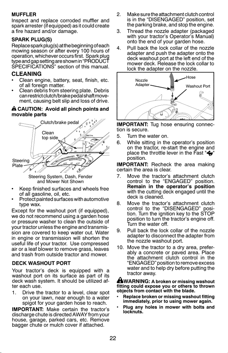
MUFFLER
Inspect
and
replace
corroded
muffler
and
spark
arrester
(if
equipped)
as
it
could
create
a
fire
hazard
and/or
damage.
SPARK
PLUG(S)
Replace
spark
plug(s)
atthe
beginning
ofeach
mowing
season
or
after
every
100
hours
of
operation,
whichever
occurs
first.
Spark
plug
type
and
gap
setting
are
shown
in“PRODUCT
SPECIFICATIONS’
section
of
this
manual.
CLEANING
«
Clean
engine,
battery,
seat,
finish,
etc.
of
all
foreign
matter.
«
Clean
debris
from
steering
plate.
Debris
canrestrictclutch/brake
pedal
shaft
move-
ment,
causing
belt
slip
and
loss
of
drive.
ACAUTION:
Avoid
all
pinch
points
and
movable
parts
oo
Steering
Plate
Steering
System,
Dash,
Fender
and
Mower
Not
Shown
*
Keep
finished
surfaces
and
wheels
free
of
all
gasoline,
oil,
etc.
*
Protect
painted
surfaces
with
automotive
type
wax.
Except
for
the
washout
port
(if
equipped),
we
do
not
recommend
using
a
garden
hose
or
pressure
washer
to
clean
the
outside
of
your
tractor
unless
the
engine
and
transmis-
sion are
covered
to
keep
water
out.
Water
in
engine
or
transmission
will
shorten
the
useful
life
of
your
tractor.
Use
compressed
air
or
a
leaf
blower
to
remove
grass,
leaves
and
trash
from
outside
tractor
and
mower.
DECK
WASHOUT
PORT
Your
tractor’s
deck
is
equipped
with
a
washout
port
on
its
surface
as
part
of
its
deck
wash
system.
It
should
be
utilized
af-
ter
each
use.
1.
Drive
the
tractor
to
a
level,
clear
spot
on
your
lawn,
near
enough
to a
water
spigot
for
your
garden
hose
to
reach.
IMPORTANT:
Make
certain
the
tractor’s
discharge
chute
is
directed
AWAY
from your
house,
garage,
parked
cars,
etc.
Remove
bagger
chute
or
muich
cover
if
attached.
22
2.
Makesurethe
attachmentclutch
control
is
in
the
“DISENGAGED?”
position,
set
the
parking
brake,
and
stop
the
engine.
3.
Thread
the
nozzle
adapter
(packaged
with
your
tractor’s
Operator’s
Manual)
onto
the
end
of
your
garden
hose.
4.
Pull
back
the
lock
collar
of
the
nozzle
adapter
and
push
the
adapter
onto
the
deck
washout
port
at
the
left
end
of
the
mower
deck.
Release
the
lock
collar
to
lock
the
adapter
on
the
nozzle.
\
Hose
a
Nozzle
Washout
Port
IMPORTANT:
Tug
hose
ensuring
connec-
tion
is
secure.
5.
Turn
the
water
on.
6.
While
sitting
in
the
operator's
position
on
the
tractor,
re-start
the
engine
and
place
the
throttle
lever
in
the
Fast
"sy"
position.
IMPORTANT:
Recheck
the
area
making
certain
the
area
is
clear.
7.
Move
the
tractor’s
attachment
clutch
control
to
the
“ENGAGED?”
position.
Remain
in
the
operator’s
position
with
the
cutting
deck
engaged
until
the
deck
is
cleaned.
8.
Move
the
tractors
attachment
clutch
control
to
the
“DISENGAGED”
posi-
tion.
Turn
the
ignition
key
to
the
STOP
position
to
turn
the
tractor’s
engine
off.
Turn
the
water
off.
9.
Pull
back
the
lock
collar
of
the
nozzle
adapter
to
disconnect
the
adapter
from
the
nozzle
washout
port.
10.
Move
the
tractor
to
a
dry
area,
prefer-
ably
a
concrete
or
paved
area.
Place
the
attachment
clutch
control
in
the
“ENGAGED?”
position
to
remove
excess
water
and
to
help
dry
before
putting
the
tractor
away.
Awarnine:
A
broken
or
missing
washout
fitting
could
expose
you
or
others
to
thrown
objects
from
contact
with
the
blade.
*
Replace
broken
or
missing
washout
fitting
immediately,
prior
to
using
mower
again.
«
Plug
any holes
in
mower
with
bolts
and
locknuts.
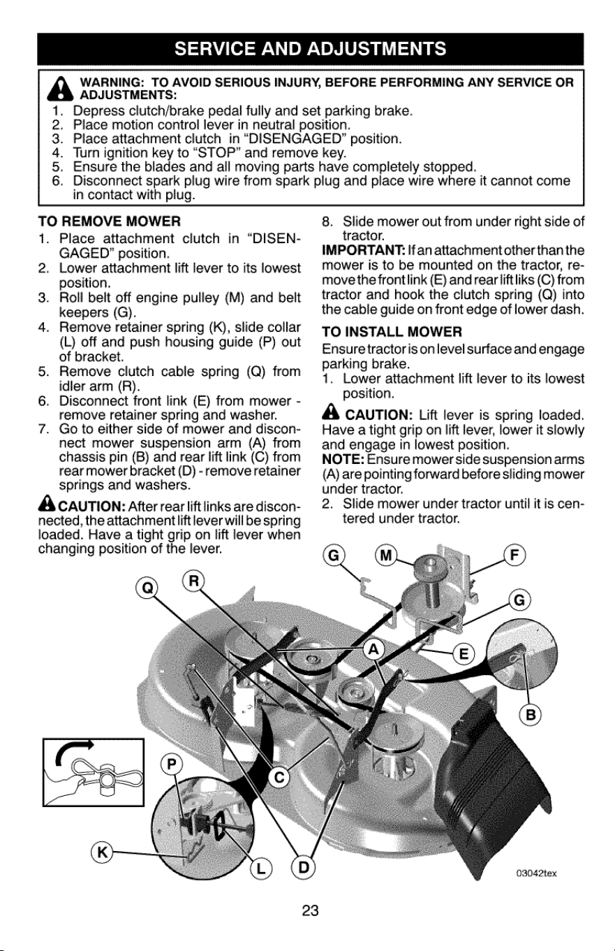
SERVICE
AND
ADJUSTMENTS
ADJUSTMENTS:
OAR
in
contact
with
plug.
WARNING:
TO
AVOID
SERIOUS
INJURY,
BEFORE
PERFORMING
ANY
SERVICE
OR
Depress
clutch/brake
pedal
fully
and
set
parking
brake.
Place
motion
control
lever
in
neutral
position.
Place
attachment
clutch
in
“DISENGAGED?”
position.
Turn
ignition
key
to
“STOP”
and
remove
key.
Ensure
the
blades
and
all
moving
parts
have
completely
stopped.
Disconnect
spark
plug wire
from
spark
plug
and
place
wire
where
it
cannot
come
TO
REMOVE
MOWER
1.
Place
attachment
clutch
in
“DISEN-
GAGED’
position.
Lower
attachment
lift
lever
to
its
lowest
position.
Roll
belt
off
engine
pulley
(M)
and
belt
keepers
(G).
Remove
retainer
spring
(K),
slide
collar
(L)
off
and
push
housing
guide
(P)
out
of
bracket.
Remove
clutch
cable
spring
(Q)
from
idler
arm
(R).
Disconnect
front
link
(E)
from
mower
-
remove
retainer
spring
and
washer.
Go
to
either
side
of
mower
and discon-
nect
mower
suspension
arm
(A)
from
chassis
pin
(B)
and
rear
lift
link
(C)
from
rear
mower
bracket
(D)
-
remove
retainer
springs
and
washers.
A
CAUTION:
After
rear
lift
links
are
discon-
nected,
the
attachment
liftlever
will
be
spring
loaded.
Have
a
tight
grip
on
lift
lever
when
changing
position
of
the
lever.
2
3.
4
a
8.
Slide
mower
out
from
under
right
side
of
tractor.
IMPORTANT:
If
an
attachment
other
than
the
mower
is
to
be
mounted
on
the
tractor,
re-
move
the
frontlink
(E)
and
rear
liftliks
(C)
from
tractor
and
hook
the
clutch
spring
(Q)
into
the
cable
guide
on
front
edge
of
lower dash.
TO
INSTALL
MOWER
Ensure
tractoris
on
level
surface
and
engage
parking
brake.
1.
Lower
attachment
lift
lever
to
its
lowest
position.
A
CAUTION:
Lift
lever
is
spring
loaded.
Have
a
tight
grip
on
lift
lever,
lower
it
slowly
and
engage
in
lowest
position.
NOTE:
Ensure
mower
side
suspension
arms
(A)
are
pointing
forward
before
sliding
mower
under
tractor.
2.
Slide
mower
under
tractor
until
it
is
cen-
tered
under
tractor.
Q
w
03042tex
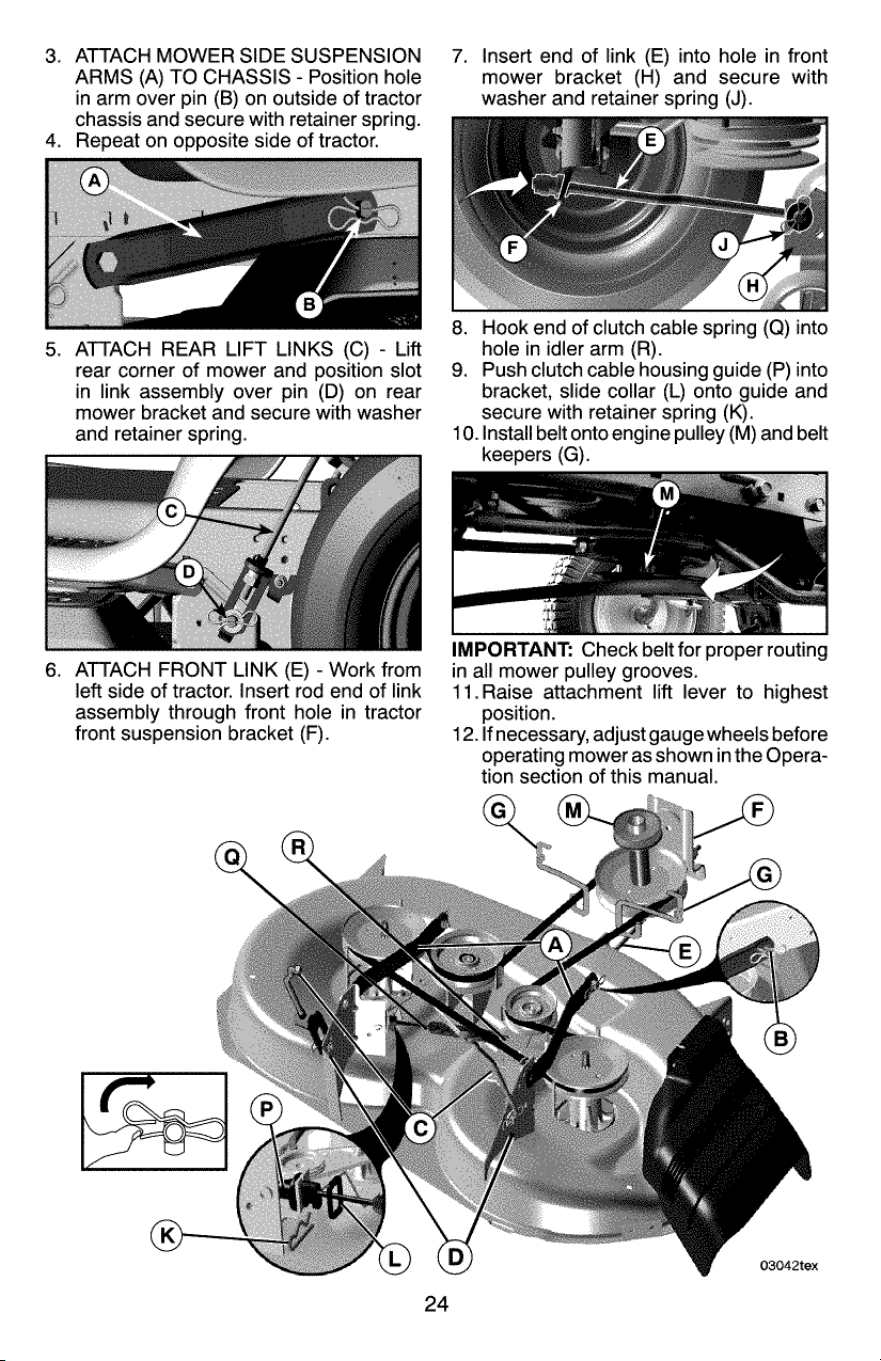
3.
ATTACH
MOWER
SIDE
SUSPENSION
ARMS
(A)
TO
CHASSIS
-
Position
hole
in
arm
over
pin
(B)
on
outside
of
tractor
chassis
and
secure
with
retainer
spring.
4.
Repeat
on
opposite
side
of
tractor.
5.
ATTACH
REAR
LIFT
LINKS
(C)
-
Lift
rear
corner
of
mower
and
position
slot
in
link
assembly
over
pin
(D)
on
rear
mower
bracket
and
secure
with
washer
and
retainer
spring.
6.
ATTACH
FRONT
LINK
(E)
-
Work
from
left
side
of
tractor.
Insert
rod
end
of
link
assembly
through
front
hole
in
tractor
front
suspension
bracket
(F).
7.
Insert
end
of
link
(E)
into
hole
in
front
mower
bracket
(H)
and
secure
with
washer
and
retainer
spring
(J).
8.
Hook
end
of
clutch
cable
spring
(Q)
into
hole
in
idler
arm
(R).
9.
Push
clutch
cable
housing
guide
(P)
into
bracket,
slide
collar
(L)
onto
guide
and
secure
with
retainer
spring
(K).
10.
Install
belt
onto
engine
pulley
(M)
and
belt
keepers
(G).
IMPORTANT:
Check
belt
for
proper
routing
in
all
mower
pulley
grooves.
11.Raise
attachment
lift
lever
to
highest
position.
12.
lfnecessary,
adjust
gauge
wheels
before
operating
mower
as
shown
in
the
Opera-
tion
section
of
this
manual.
03042tex
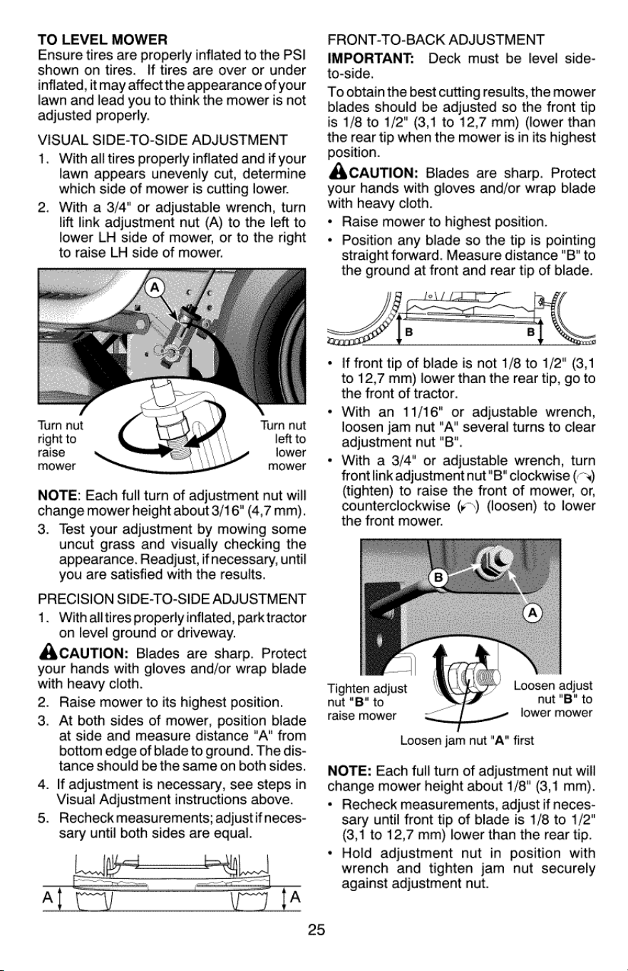
TO
LEVEL
MOWER
Ensure
tires
are
properly
inflated
to
the
PSI
shown
on
tires.
If
tires
are
over
or
under
inflated,
it
may
affect
the
appearance
of
your
lawn
and
lead
you
to
think
the
mower
is
not
adjusted
properly.
VISUAL
SIDE-TO-SIDE
ADJUSTMENT
1.
With
all
tires
properly
inflated
and
if
your
lawn
appears
unevenly
cut,
determine
which
side
of
mower
is
cutting
lower.
2.
With
a
3/4"
or
adjustable
wrench,
turn
lift
link
adjustment
nut
(A)
to
the
left
to
lower
LH
side
of
mower,
or
to
the
right
to
raise
LH
side
of
mower.
Turn
nut
Turn
nut
right
to
left
to
raise
lower
mower mower
NOTE:
Each
full
turn
of
adjustment
nut
will
change
mower
height
about
3/16"
(4,7
mm).
3.
Test
your
adjustment
by
mowing
some
uncut grass
and
visually
checking
the
appearance.
Readjust,
ifnecessary,
until
you
are
satisfied
with
the
results.
PRECISION
SIDE-TO-SIDE
ADJUSTMENT
1.
With
alltires
properly
inflated,
park
tractor
on
level
ground
or
driveway.
ACAUTION:
Blades
are
sharp.
Protect
your
hands
with
gloves
and/or
wrap
blade
with
heavy
cloth.
2.
Raise
mower
to
its
highest
position.
3.
At
both
sides
of
mower,
position
blade
at
side
and
measure
distance
"A"
from
bottom
edge
of
blade
to
ground.
The
dis-
tance
should
be
the
same
on
both
sides.
4.
lf
adjustment
is
necessary,
see steps
in
Visual
Adjustment
instructions
above.
5.
Recheck
measurements;
adjust
ifneces-
sary
until
both
sides
are
equal.
FRONT-TO-BACK
ADJUSTMENT
IMPORTANT:
Deck
must
be
level
side-
to-side.
To
obtain
the
best
cutting
results,
the
mower
blades should
be
adjusted
so
the
front
tip
is
1/8
to
1/2"
(3,1
to
12,7
mm)
(lower
than
the
rear
tip
when
the
mower
is
in
its
highest
position.
AXCAUTION:
Blades
are
sharp.
Protect
your
hands
with
gloves
and/or
wrap
blade
with
heavy
cloth.
*
Raise
mower
to
highest
position.
*
Position
any
blade
so
the
tip
is
pointing
straight
forward.
Measure
distance
“B"
to
the
ground
at
front
and
rear
tip
of
blade.
rat
*
If
front
tip
of
blade
is
not
1/8
to
1/2"
(3,1
to
12,7
mm)
lower
than
the
rear
tip,
go
to
the
front
of
tractor.
«
With
an
11/16"
or
adjustable
wrench,
loosen
jam
nut
"A"
several
turns
to
clear
adjustment
nut
"B".
«
With
a
3/4"
or
adjustable
wrench,
turn
frontlink
adjustment
nut"B"
clockwise
(~~)
(tighten)
to
raise the
front
of
mower,
or,
counterclockwise
(¥>)
(loosen)
to
lower
the
front
mower.
Tighten
adjust
Loosen
adjust
nut
"B"
to
nut
"B"
to
raise
mower
lower
mower
Loosen
jam
nut
"A"
first
NOTE:
Each
full
turn
of
adjustment
nut
will
change
mower
height
about
1/8"
(3,1
mm).
*
Recheck
measurements,
adjust
if
neces-
sary
until
front
tip
of
blade
is
1/8
to
1/2"
(3,1
to
12,7
mm)
lower
than
the
rear
tip.
*
Hold
adjustment
nut
in
position
with
wrench
and
tighten
jam
nut
securely
against
adjustment
nut.
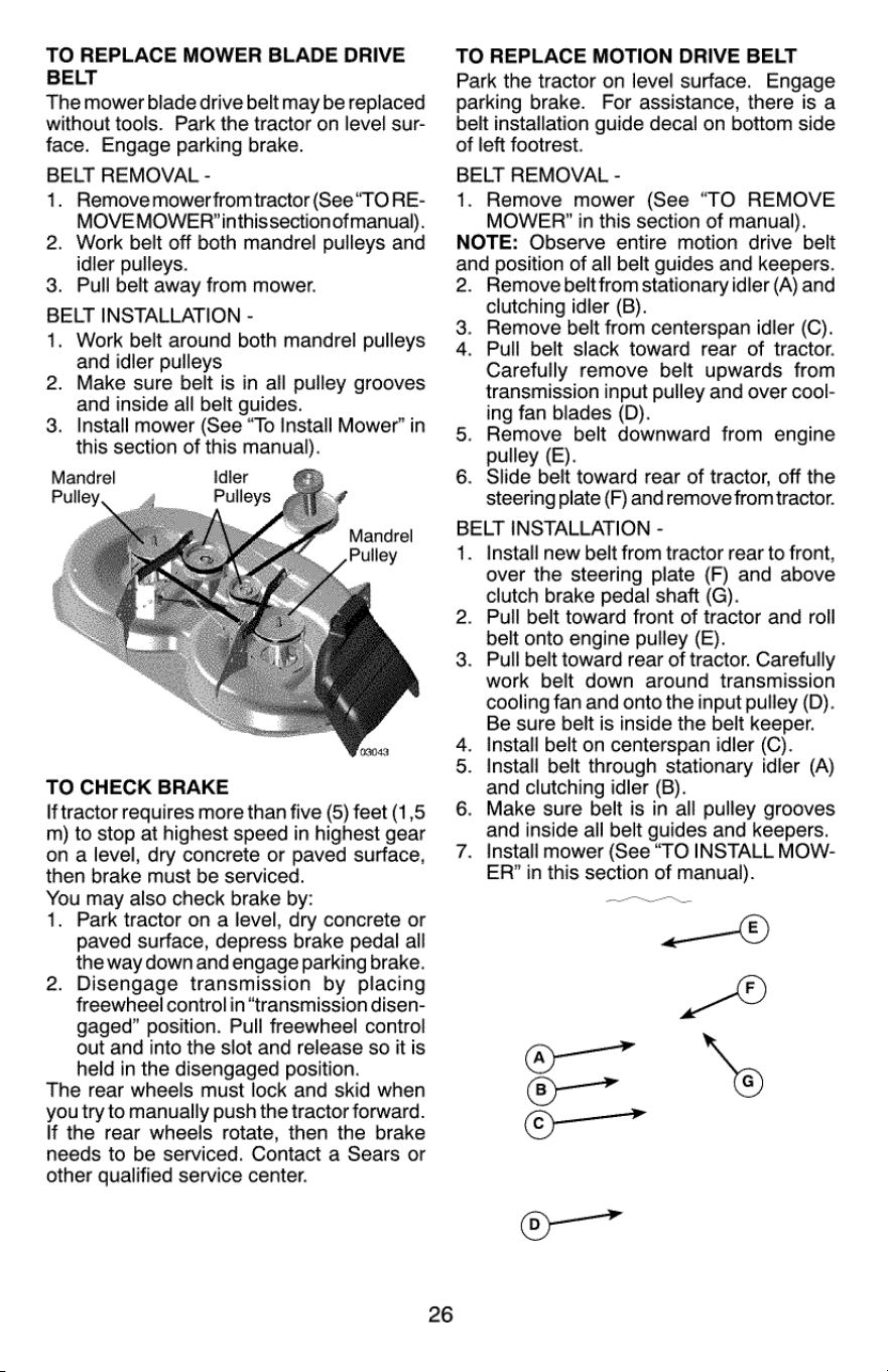
TO
REPLACE
MOWER
BLADE
DRIVE
BELT
The
mower
blade
drive
belt
may
be
replaced
without
tools.
Park
the
tractor
on
level sur-
face.
Engage
parking
brake.
BELT
REMOVAL
-
1.
Remove
mower
fromtractor
(See
“TO
RE-
MOVE
MOWER’
inthis
section
ofmanual).
Work
belt
off
both
mandrel
pulleys
and
idler
pulleys.
3.
Pull
belt
away
from
mower.
BELT
INSTALLATION
-
1.
Work
belt
around
both
mandrel
pulleys
and
idler
pulleys
2.
2.
Make
sure
belt
is
in
all
pulley
grooves
and
inside
all
belt
guides.
3.
Install
mower
(See
“To
Install
Mower”
in
this
section
of
this
manual).
Mandrel
Idier
Pulley
TO
CHECK
BRAKE
If
tractor
requires
more
than
five
(5)
feet
(1,5
m)
to
stop
at
highest
speed
in
highest
gear
on
a
level,
dry
concrete
or
paved
surface,
then
brake
must
be
serviced.
You
may
also
check
brake
by:
1.
Park
tractor
on
a
level,
dry
concrete
or
paved
surface,
depress
brake
pedal
all
the
way
down
and
engage
parking
brake.
Disengage
transmission
by
placing
freewheel
control
in
“transmission
disen-
gaged”
position.
Pull
freewheel
control
out
and
into
the
slot
and
release
so
it
is
held
in
the
disengaged
position.
The
rear
wheels
must
lock
and
skid
when
you
try
to
manually
push
the
tractor
forward.
If
the
rear
wheels
rotate,
then
the
brake
needs
to
be
serviced.
Contact
a
Sears
or
other
qualified
service
center.
26
TO
REPLACE
MOTION
DRIVE
BELT
Park
the
tractor
on
level
surface.
Engage
parking
brake.
For
assistance,
there
is
a
belt
installation
guide
decal
on
bottom
side
of
left
footrest.
BELT
REMOVAL
-
1.
Remove
mower
(See
“TO
REMOVE
MOWER?’
in
this
section
of
manual).
NOTE:
Observe
entire
motion
drive
belt
and
position
of
all
belt
guides
and
keepers.
2.
Remove
belt
from
stationary
idler
(A)
and
clutching
idler
(B).
Remove
beit
from
centerspan
idler
(C).
Pull
belt
slack
toward
rear
of
tractor.
Carefully
remove
belt
upwards
from
transmission
input
pulley
and
over
cool-
ing
fan
blades
(D).
Remove
belt
downward
from
engine
pulley
(E).
Slide
belt
toward
rear
of
tractor,
off
the
steering
plate
(F)
and
remove
from
tractor.
BELT
INSTALLATION
-
.
Install
new
belt
from
tractor
rear
to
front,
over
the
steering
plate
(F)
and
above
clutch
brake
pedal
shaft
(G).
Pull belt
toward
front
of
tractor
and
roll
belt
onto
engine
pulley
(E).
Pull belt
toward
rear
of
tractor.
Carefully
work
belt
down
around
transmission
cooling
fan
and
onto
the
input
pulley
(D).
Be
sure
belt
is
inside
the
belt
keeper.
Install
belt
on
centerspan
idler
(C).
Install
belt
through
stationary
idler
(A)
and
clutching
idler
(B).
Make
sure
belt
is
in
all
pulley
grooves
and
inside
all
belt
guides
and
keepers.
Install
mower
(See
“TO
INSTALL
MOW-
ER’
in
this
section
of
manual).
3.
4.
N
Oo
OF
©
ae
No
1
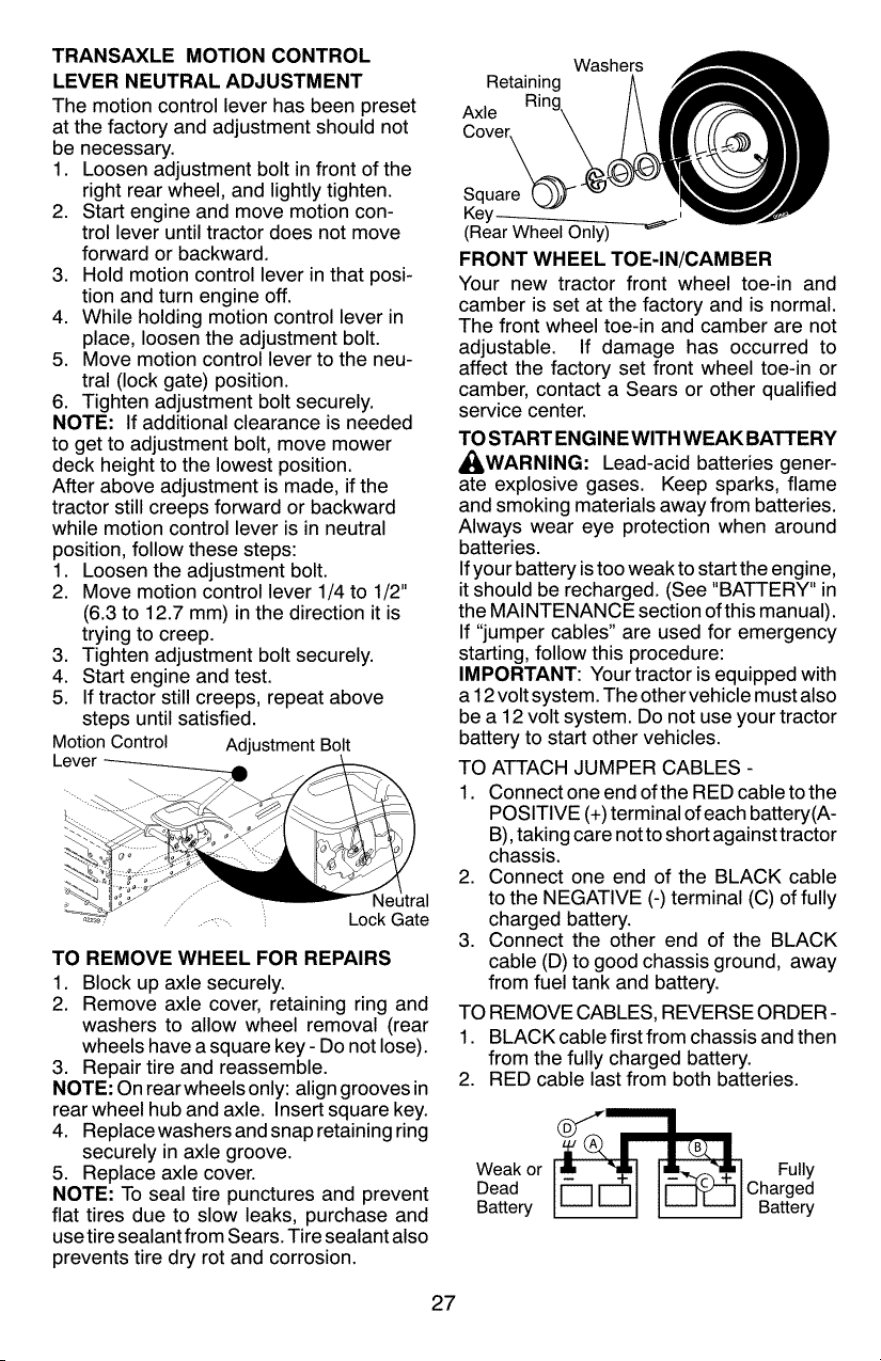
TRANSAXLE
MOTION
CONTROL
LEVER
NEUTRAL
ADJUSTMENT
The
motion
control
lever
has
been
preset
at
the
factory
and
adjustment
should
not
be
necessary.
1.
Loosen
adjustment
bolt
in
front
of
the
right
rear
wheel,
and
lightly
tighten.
Start
engine
and
move
motion
con-
trol
lever
until
tractor
does
not
move
forward
or
backward.
Hold
motion
control
lever
in
that
posi-
tion
and
turn
engine
off.
While
holding
motion
control
lever
in
place,
loosen
the
adjustment
bolt.
Move
motion
control
lever
to
the
neu-
tral
(lock
gate) position.
6.
Tighten
adjustment
bolt
securely.
NOTE:
If
additional
clearance
is
needed
to
get
to
adjustment
bolt,
move
mower
deck
height
to
the
lowest
position.
After
above
adjustment
is
made,
if
the
tractor
still
creeps
forward
or
backward
while
motion
control
lever
is
in
neutral
position,
follow
these
steps:
1.
Loosen
the
adjustment
bolt.
2.
Move
motion
control
lever
1/4
to
1/2"
(6.3
to
12.7
mm)
in
the
direction
it
is
trying
to
creep.
Tighten
adjustment
bolt
securely.
Start
engine
and
test.
If
tractor
still
creeps,
repeat
above
steps
until
satisfied.
Motion
Control
Adjustment
Bolt
2.
3.
4.
5.
oP
&
Lock
Gate
TO
REMOVE
WHEEL
FOR
REPAIRS
1.
Block
up
axle
securely.
2.
Remove
axie
cover,
retaining
ring
and
washers
to
allow
wheel
removal
(rear
wheels
have
a
square
key
-
Do
not
lose).
3.
Repair
tire
and
reassemble.
NOTE:
Onrear
wheels
only:
align
grooves
in
rear
wheel
hub
and
axle.
Insert
square
key.
4.
Replace
washers
and
snap
retaining
ring
securely
in
axle
groove.
5.
Replace
axle
cover.
NOTE:
To
seal
tire
punctures
and
prevent
flat
tires
due
to
slow
leaks,
purchase
and
use
tire
sealant
from
Sears.
Tire
sealant
also
prevents
tire
dry
rot
and
corrosion.
27
Washers
Retaining
Axle
Ping
Cover,
seas)
Key
————____
(Rear
Wheel
Only)
FRONT
WHEEL
TOE-IN/CAMBER
Your
new
tractor
front
wheel
toe-in
and
camber
is
set
at
the
factory
and
is
normal.
The
front
wheel
toe-in
and
camber
are
not
adjustable.
If
damage
has
occurred
to
affect
the
factory
set
front
wheel
toe-in
or
camber,
contact
a
Sears
or
other
qualified
service
center.
TO
START
ENGINE
WITH
WEAKBATTERY
AWARNING:
Lead-acid
batteries
gener-
ate
explosive
gases.
Keep
sparks,
flame
and
smoking
materials
away
from
batteries.
Always
wear
eye
protection
when
around
batteries.
If
your
battery
is
too
weak
to
start
the
engine,
it
should
be
recharged.
(See
"BATTERY"
in
the
MAINTENANCE
section
of
this
manual).
If
“umper
cables”
are
used
for
emergency
starting,
follow
this
procedure:
IMPORTANT:
Your
tractor
is
equipped
with
a12voltsystem.
The
other
vehicle
must
also
be
a
12
volt
system.
Do
not
use
your
tractor
battery
to
start
other
vehicles.
TO
ATTACH
JUMPER
CABLES
-
1.
Connect
one
end
ofthe
RED
cable
to
the
POSITIVE
(+)
terminal
of
each
battery(A-
B),
taking
care
notto
short
againsttractor
chassis.
Connect
one
end
of
the
BLACK
cable
to
the
NEGATIVE
(-)
terminal
(C)
of
fully
charged
battery.
Connect
the
other
end
of
the
BLACK
cable
(D)
to
good
chassis
ground,
away
from
fuel
tank
and
battery.
TO
REMOVE
CABLES,
REVERSE
ORDER
-
1.
BLACK
cable
first
from
chassis
and
then
from
the
fully
charged
battery.
2.
RED
cable
last
from
both
batteries.
Weak
or
Dead
Battery
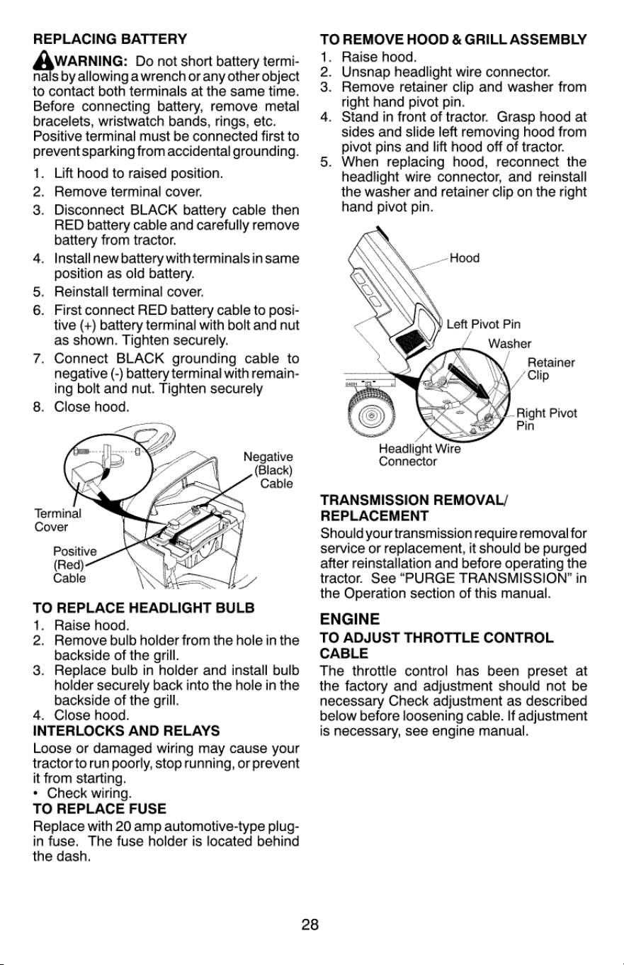
REPLACING
BATTERY
WARNING:
Do
not
short
battery
termi-
nals
by
allowing
awrench
or
any
other
object
to
contact
both
terminals
at
the
same
time.
Before
connecting
battery,
remove
metal
bracelets,
wristwatch
bands,
rings,
etc.
Positive
terminal
must
be
connected
first
to
prevent
sparking
from
accidental
grounding.
1.
Lift
hood
to
raised
position.
2.
Remove
terminal
cover.
3.
Disconnect
BLACK
battery
cable
then
RED
battery
cable
and
carefully
remove
battery
from
tractor.
4.
Installnew
battery
withterminals
in
same
position
as
old
battery.
5.
Reinstall
terminal
cover.
6.
First
connect
RED
battery
cable
to
posi-
tive
(+)
battery
terminal
with
bolt
and
nut
as
shown.
Tighten
securely.
7.
Connect
BLACK
grounding
cable
to
negative
(-)
battery
terminal
with
remain-
ing
bolt
and
nut.
Tighten
securely
8.
Close
hood.
Negative
(Black)
Cable
Terminal
Cover
Positive
(Red)
Cable
6
:
(
As
TO
REPLACE
HEADLIGHT
BULB
4.
Raise
hood.
2.
Remove
bulb
holder
from
the
hole
in
the
backside
of
the
grill.
3.
Replace
bulb
in
holder
and
install
bulb
holder
securely
back
into
the
hole
in
the
backside
of
the
grill.
4.
Close
hood.
INTERLOCKS
AND
RELAYS
Loose
or
damaged
wiring
may
cause
your
tractor
to
run
poorly,
stop
running,
or
prevent
it
from
starting.
*
Check
wiring.
TO
REPLACE
FUSE
Replace
with
20
amp
automotive-type
plug-
in
fuse.
The
fuse
holder
is
located
behind
the
dash.
28
TO
REMOVE
HOOD
&
GRILL
ASSEMBLY
Raise
hood.
Unsnap
headlight
wire
connector.
Remove
retainer
clip
and
washer
from
right
hand
pivot
pin.
Stand
in
front
of
tractor.
Grasp
hood
at
sides
and
slide
left
removing
hood
from
pivot
pins
and
lift
hood
off
of
tractor.
When
replacing
hood,
reconnect
the
headlight
wire
connector,
and
reinstall
the
washer
and
retainer
clip
on
the
right
hand
pivot
pin.
-P
YN
Retainer
Clip
y
Right
Pivot
Pin
Headlight
Wire
Connector
TRANSMISSION
REMOVAL/
REPLACEMENT
Should
your
transmission
require
removal
for
service
or
replacement,
it
should
be
purged
after
reinstallation
and
before
operating
the
tractor.
See
“PURGE
TRANSMISSION?”
in
the
Operation
section
of
this
manual.
ENGINE
TO
ADJUST
THROTTLE
CONTROL
CABLE
The
throttle
control
has
been
preset
at
the
factory
and
adjustment
should
not
be
necessary
Check
adjustment
as
described
below
before
loosening
cable.
If
adjustment
is
necessary,
see
engine
manual.

STORAGE
Immediately
prepare
your
tractor
for
storage
at
the
end
of
the
season
or
if
the
tractor
will
not
be
used
for
30
days
or
more.
WARNING:
Never
store
the
tractor
with
gasoline
in
the
tank
inside
a
building
where
fumes
may
reach
an
open
flame
or
spark.
Allow
the
engine
to
cool
before
storing
in
any
enclosure.
TRACTOR
Remove
mower
from
tractor
for
winter
stor-
age.
When
mower
is
to
be
stored
for
a
period
of
time,
clean
it
thoroughly,
remove
all
dirt,
grease,
leaves,
etc.
Storeinaclean,
dry
area.
1.
Clean
entire
tractor
(See
“CLEANING?
in
the
Maintenance
section
of
this
manual).
Inspect
and
replace
belts,
if
necessary
(See
belt
replacement
instructions
in
the
Service
and
Adjustments
section
of
this
manual).
Lubricate
as
shown
in
the
Maintenance
section
of
this
manual.
Ensure
that
all
nuts,
bolts
and
screws
are
securely
fastened.
Inspect
moving
parts
for
damage,
breakage
and
wear.
Replace
if
necessary.
Touch
up
all
rusted
or
chipped
paint
surfaces;
sand
lightly
before
painting.
BATTERY
*
Fully
charge
the
battery
for
storage.
After
a
period
of
time
in
storage,
battery
may
require
recharging.
To
help
prevent
corrosion
and
power
leakage
during
long
periods
of
storage,
battery
cables
should
be
disconnected
and
battery
cleaned
thoroughly
(see
“TO
CLEAN
BATTERY
AND
TERMINALS?’
in
the
Maintenance
section
of
this
manual).
After
cleaning,
leave
cables
disconnected
and
place
cables
where
they
cannot
come
in
contact
with
battery
terminals.
If
battery
is
removed
from
tractor
for
storage,
do
not
store
battery
directly on
concrete
or
damp
surfaces.
If
unit
is
equipped
with
battery
indicator/
charging
plug, an
optional
charging
unit
may
be
purchased
and
connected
to
the
unit
to
charge
the
battery
during
long
term
storage.
Inspect
and
clean
the
battery
terminals
as
needed
prior
to
long
term
storage
with
charger
connected.
2.
5.
29
ENGINE
FUEL
SYSTEM
IMPORTANT:
it
is
important
to
prevent
gum
deposits
from
forming
in
essential
fuel
system
parts
such
as
carburetor,
fuel
hose,
ortank
during
storage.
Also,
alcohol
blended
fuels (called
gasohol
or
using
ethanol
or
methanol)
can
attract
moisture
which
leads
to
separation
and
formation
of
acids
during
storage.
Acidic
gas
can
damage
the
fuel
system
of
an
engine
while
in
storage.
*
Empty
the
fuel
tank
by
starting
the
engine
and
letting
it
run
until
the
fuel
lines
and
carburetor
are
empty.
«
Never
use
engine
or
carburetor
cleaner
products
in
the
fuel
tank
or
permanent
damage
may
occur.
*
Use
fresh
fuel
next
season.
NOTE:
Fuel
stabilizer
is
an
acceptable
al-
ternative
in
minimizing
the
formation
of
fuel
gum
deposits
during
storage.
Add
stabilizer
to
gasoline
in
fuel
tank
or
storage
container.
Always
follow
the
mix
ratio
found
on
stabilizer
container.
Run
engine
at
least
10
minutes
after
adding
stabilizer
to
allow
the
stabilizer
to
reach
the
carburetor.
Do
not
empty
the
gas
tank
and
carburetor
if
using
fuel
stabilizer.
ENGINE
OIL
Drain
oil
(with
engine
warm)
and
replace
with
clean
engine
oil.
(See
“ENGINE”
in
the
Maintenance
section
of
this
manual).
CVEINDER(S)
Remove
spark
plug(s).
Pour one
ounce
(29.5
mL)
of
oil
through
spark
plug
hole(s)
into
cylinder(s).
Turn
ignition
key
to
“START”
position
for
a
few
seconds
to
distribute
oil.
4.
Replace
with
new
spark
plug(s).
OTHER
*
Donot
store
gasoline
from
one
season
to
another.
Replace
your
gasoline
can
ifyourcan
starts
to
rust.
Rust
and/or
dirt
in
your
gasoline
will
cause
problems.
If
possible,
store
your
tractor
indoors
and
cover
itto
give
protection
from
dust
and
dirt.
Cover
your
tractor
with
a
suitable
protec-
tive
cover
that
does
not
retain
moisture.
Do
notuse
plastic.
Plastic
cannot
breathe
which
allows
condensation
to
form
and
will
cause
your
tractor
to
rust.
IMPORTANT:
Never
cover
tractor
while
engine
and
exhaust
areas
are
still
warm.
2.
3.
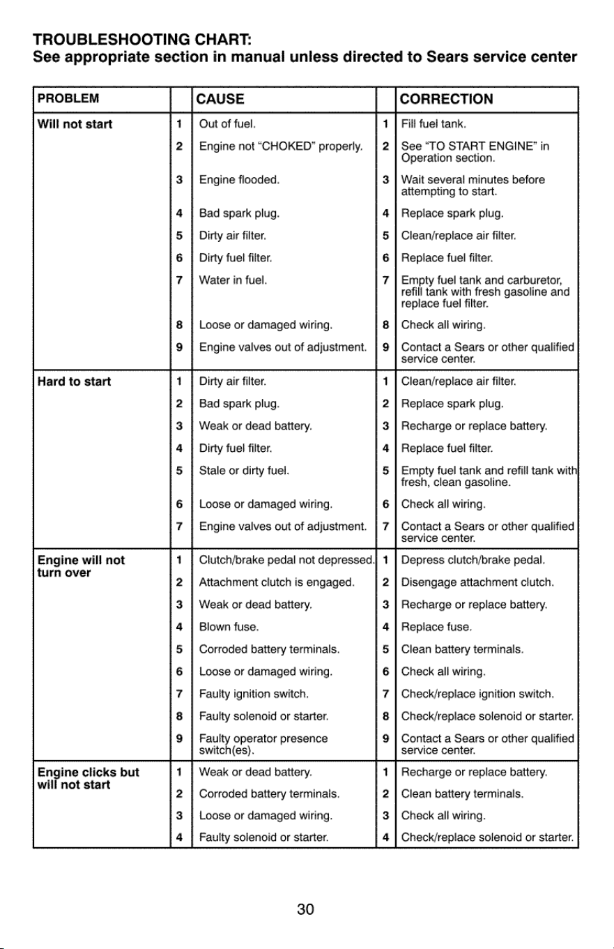
TROUBLESHOOTING
CHART:
See
appropriate
section
in
manual
unless
directed
to
Sears
service
center
PROBLEM
CAUSE
CORRECTION
Will
not
start
1
|
Out
of
fuel.
1
|
Fill
fuel
tank.
2
|
Engine
not
“CHOKED”
properly.
|
2
|
See
“TO
START
ENGINE?’
in
Operation
section.
3
|
Engine
flooded.
3
|
Wait
several
minutes
before
attempting
to
start.
4
| Bad
spark
plug.
4
|
Replace
spark
plug.
5
|
Dirty
air
filter.
5
|
Clean/replace
air
filter.
6
|
Dirty
fuel
filter.
6
|
Replace
fuel
filter.
7
|
Water
in
fuel.
7
|
Empty
fuel
tank
and
carburetor,
refill
tank
with
fresh
gasoline
and
replace
fuel
filter.
8
|
Loose
or
damaged
wiring.
8
|
Check
all
wiring.
Engine
valves
out
of
adjustment.
Contact
a
Sears
or
other
qualified
service
center.
Hard
to
start
1
|
Dirty
air
filter.
1
|
Clean/replace
air
filter.
2
| Bad
spark
plug.
2
|
Replace
spark
plug.
3
|
Weak
or
dead
battery.
3
|
Recharge
or
replace
battery.
4
}
Dirty
fuel
filter.
4
|
Replace
fuel
filter.
5
|
Stale
or
dirty fuel.
5
|
Empty
fuel
tank
and
refill
tank
with|
fresh,
clean
gasoline.
Loose
or
damaged
wiring.
Check
all
wiring.
Engine
valves
out
of
adjustment.
Contact
a
Sears
or
other
qualified
service
center.
Engine
will
not
1
|
Clutch/brake
pedal
not
depressed
1
|
Depress
clutch/brake
pedal.
turn
over
2
|
Attachment
clutch
is
engaged.
2
|
Disengage
attachment
clutch.
3
|
Weak
or
dead
battery.
3
|
Recharge
or
replace
battery.
4
|
Blown
fuse.
4
|
Replace
fuse.
5
|
Corroded
battery
terminals.
5
| Clean
battery
terminals.
6
|
Loose
or
damaged
wiring.
6
|
Check
all
wiring.
7
|
Faulty
ignition
switch.
7
|
Check/repiace
ignition
switch.
8
|
Faulty
solenoid
or
starter.
8
|
Check/replace
solenoid
or
starter.
9
|}
Faulty
operator
presence
9
|
Contact
a
Sears
or
other
qualified
switch(es).
service
center.
Engine
clicks
but
1
|
Weak
or
dead
battery.
1
|
Recharge
or
replace
battery.
will
not
start
. .
2
|
Corroded
battery
terminals.
2
|
Clean
battery
terminals.
3
|
Loose
or
damaged
wiring.
3
|
Check
all
wiring.
4
|
Faulty
solenoid
or
starter.
4
|
Check/replace
solenoid
or
starter.
30
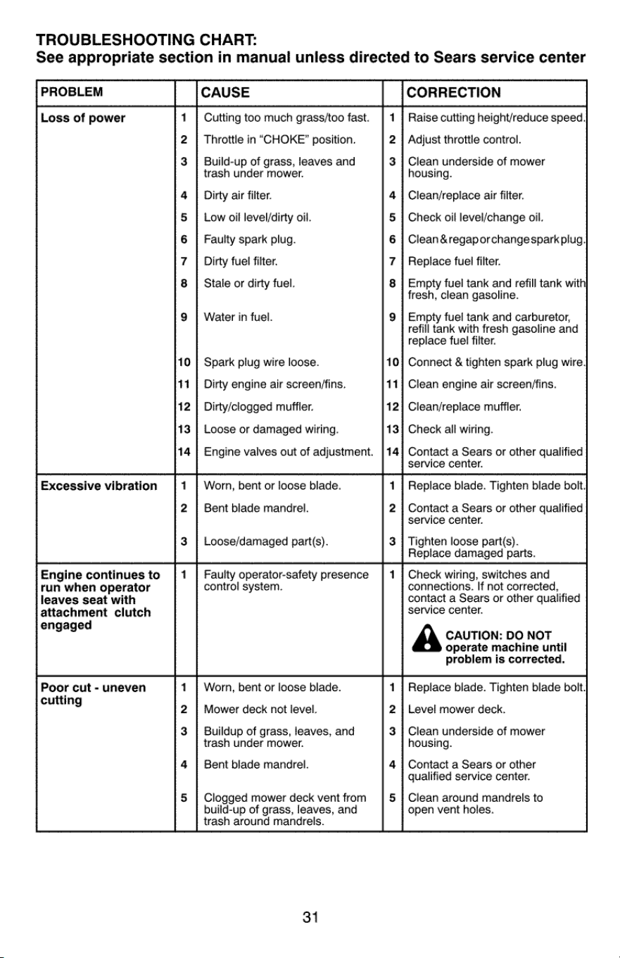
TROUBLESHOOTING
CHART:
See
appropriate
section
in
manual
unless
directed
to
Sears
service
center
PROBLEM
CAUSE
CORRECTION
Loss
of
power
Cutting
too
much
grass/too
fast.
Raise
cutting
height/reduce
speed.
build-up
of
grass,
leaves,
and
trash
around
mandrels.
2
|
Throttle
in
“CHOKE”
position.
2
|
Adjust
throttle
control.
Build-up
of
grass,
leaves
and
Clean
underside
of
mower
trash
under
mower.
housing.
4
|
Dirty
air
filter.
4
|
Clean/replace
air
filter.
5
|
Low
oil
level/dirty
oil.
5
|
Check
oil
level/change
oil.
6
|
Faulty
spark
plug.
6
|
Clean
®ap
or
change
spark
plug.
7
|
Dirty
fuel
filter.
7
|
Replace
fuel
filter.
8
|
Stale
or
dirty
fuel.
8
|
Empty
fuel
tank
and
refill
tank
with
fresh,
clean
gasoline.
9
|
Water
in
fuel.
9
|
Empty
fuel
tank
and
carburetor,
refill
tank
with
fresh
gasoline
and
replace
fuel
filter.
10
|
Spark
plug wire
loose.
10}
Connect
&
tighten
spark
plug
wire.
11
|
Dirty
engine
air
screen/fins.
11]
Clean
engine
air
screen/fins.
12
|
Dirty/clogged
muffler.
12|
Clean/replace
muffler.
13
|
Loose
or
damaged
wiring.
13}
Check
ail
wiring.
14
|
Engine
valves
out
of
adjustment.
[14]
Contact
a
Sears
or
other
qualified
service
center.
Excessive
vibration
1
|
Worn,
bent
or
loose
blade.
1
|
Replace
blade.
Tighten
blade
bolt,
2
|}
Bent
blade
mandrel.
2
|
Contact
a
Sears
or
other
qualified
service
center.
3
|
Loose/damaged
part(s).
3
|
Tighten
loose
part(s).
Replace
damaged
parts.
Engine
continues
to
|
1
|
Faulty
operator-safety
presence
|
1
| Check
wiring,
switches
and
run
when
operator
control
system.
connections.
If
not
corrected,
leaves
seat
with
contact
a
Sears
or
other
qualified
attachment
clutch
service
center.
engaged
A
CAUTION:
DO
NOT
operate
machine
until
problem
is
corrected.
Poor
cut
-
uneven
1
|
Worn,
bent
or
loose
blade.
1
|
Replace
blade.
Tighten
blade
bolt.
cuttin
9
2
|
Mower
deck
not
level.
2
|
Level
mower
deck.
Buildup
of
grass,
leaves,
and
3
|
Clean
underside
of
mower
trash
under
mower.
housing.
4
|
Bent
blade
mandrel.
4
|
Contact
a
Sears
or
other
qualified
service
center.
5
|
Clogged
mower
deck
vent
from
5
|
Clean
around
mandrels
to
open
vent
holes.
31
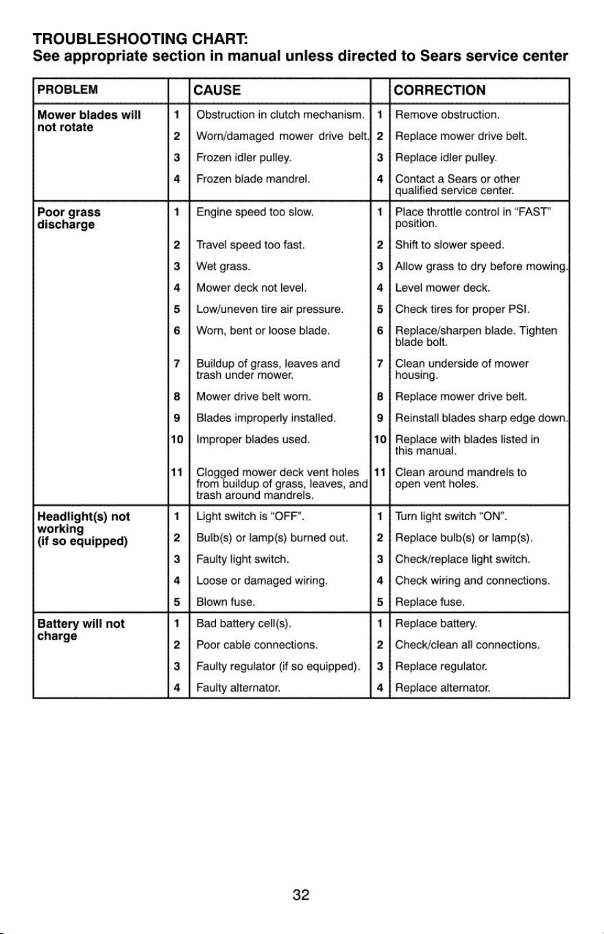
TROUBLESHOOTING
CHART:
See
appropriate
section
in
manual
unless
directed
to
Sears
service
center
PROBLEM
CAUSE
CORRECTION
Mower
blades
will
1
|
Obstruction
in
clutch
mechanism.
|
1
|
Remove
obstruction.
not
rotate
2
|
Worn/damaged
mower
drive belt
2
|
Replace
mower
drive
belt.
3
|
Frozen
idler
pulley.
3
|
Replace
idier
pulley.
4
|
Frozen
blade
mandrel.
4
|
Contact
a
Sears
or
other
qualified
service
center.
Poor
grass
1
|
Engine
speed
too
slow.
1
|
Place
throttle
control
in
“FAST”
discharge
position.
2
|
Travel
speed
too
fast.
2
|
Shift
to
slower
speed.
3
|
Wet
grass.
3
|
Allow grass
to
dry
before
mowing,
4
|
Mower
deck
not
level.
4
|
Level
mower
deck.
5
|
Low/uneven
tire
air
pressure.
5
|
Check
tires
for
proper
PSI.
6
|
Worn,
bent
or
loose
blade.
6
|
Replace/sharpen
blade.
Tighten
blade
bolt.
7
|
Buildup
of
grass,
leaves
and
7
|
Clean
underside
of
mower
trash
under
mower.
housing.
Mower
drive
belt
worn.
Replace
mower
drive
belt.
9
|
Blades
improperly
installed.
9
|
Reinstall
blades
sharp
edge
down,
10
|
Improper
blades
used.
10|
Replace
with
blades
listed
in
this
manual.
11
|
Clogged
mower
deck
vent
holes
[11]
Clean
around
mandrels
to
from
buildup
of
grass,
leaves,
and
open
vent
holes.
trash
around
mandrels.
Headlight(s)
not
1
|
Light
switch
is
“OFF”.
1
|
Turn
light
switch
“ON”.
if
so
eduipped)
2
|
Bulb(s)
or
lamp(s)
burned
out.
2
|
Replace
bulb(s)
or
lamp(s).
3
|
Faulty
light
switch.
3
|
Check/replace
light
switch.
4
|
Loose
or
damaged
wiring.
4
|
Check
wiring
and
connections.
5
|
Blown
fuse.
5
|
Replace
fuse.
Battery
will
not
1
|
Bad
battery
cell(s).
1
|
Replace
battery.
charge
2
|
Poor
cable
connections.
2
|
Check/clean
ail
connections.
3
|
Faulty
regulator
(if
so
equipped).
|
3
|
Replace
regulator.
4
|
Faulty
alternator.
4
|
Replace
alternator.
32
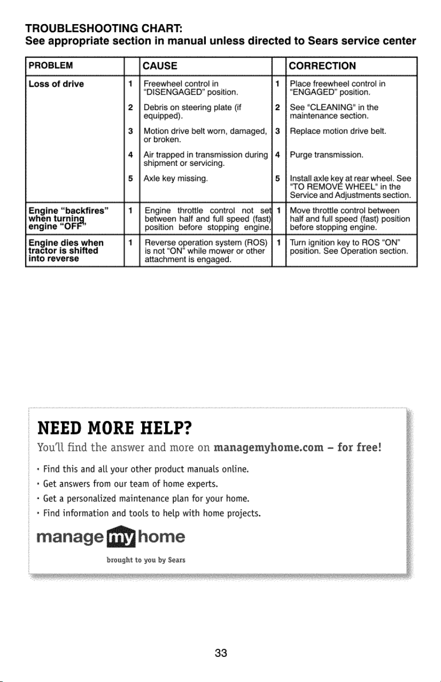
TROUBLESHOOTING
CHART:
See
appropriate
section
in
manual
unless
directed
to
Sears
service
center
PROBLEM
CAUSE
CORRECTION
Loss
of
drive
Freewheel
control
in
“DISENGAGED’
position.
Debris
on
steering
plate
(if
equipped).
Motion
drive
belt
worn,
damaged,
or
broken.
Air
trapped
in
transmission
during
shipment
or
servicing.
Axle
key
missing.
3
4
Place
freewheel
control
in
“ENGAGED”
position.
See
"CLEANING?
in
the
maintenance
section.
Replace
motion
drive
belt.
Purge
transmission.
Install
axle
key
at
rear
wheel.
See
"TO
REMOVE
WHEEL"
in
the
Service
and
Adjustments
section.
Engine
“backfires”
when
turnin
engine
“OFF”
Engine
throttle
contro!
not
set
between
half
and
full
speed
(fast)
position
before
stopping
engine.
Move
throttle
control
between
half
and
full
speed
(fast)
position
before
stopping
engine.
Engine
dies
when
tractor
is
shifted
into
reverse
Reverse
operation
system
(ROS)
is
not
“ON”
while
mower
or
other
attachment
is
engaged.
Turn
ignition
key
to
ROS
“ON”
position.
See
Operation
section.
NEED
MORE
HELP?
You'll
find
the
answer
and
more
on
managemyhome.com
—
for
free!
«
Find
this
and
all
your
other
product
manuals
online.
*
Get
answers
from
our
team
of
home
experts.
«
Get
a
personalized
maintenance
plan
for
your
home.
»
Find
information
and
tools
to
help
with
home
projects.
manage
fpyhome
brought
te
you
by
Sears
33
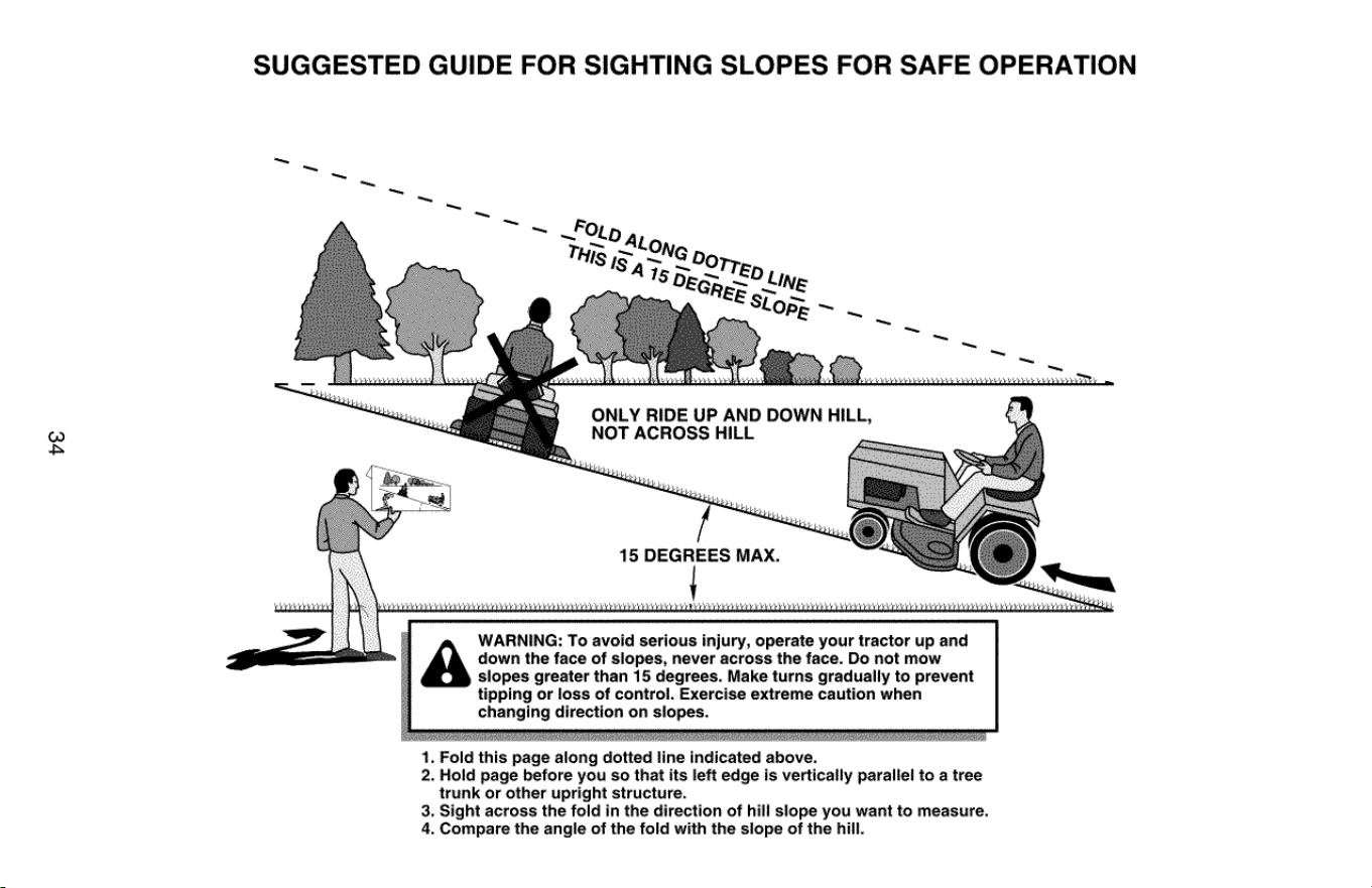
ve
SUGGESTED
GUIDE
FOR
SIGHTING
SLOPES
FOR
SAFE
OPERATION
ONLY
RIDE
UP
AND
DOWN
HILL,
NOT
ACROSS
HILL
15
DEGREES
MAX.
at
down
the
face
of
slopes,
never
across
the
face.
Do
not
mow
slopes
greater
than
15
degrees.
Make
turns
gradually
to
prevent
tipping
or
loss
of
control.
Exercise
extreme
caution
when
changing
direction
on
slopes.
'
WARNING:
To
avoid
serious
injury,
operate
your
tractor
up
and
1.
Fold
this
page
along
dotted
line
indicated
above.
2.
Hold
page
before
you
so that
its
left
edge
is
vertically
parallel
to
a
tree
trunk
or
other
upright
structure.
3.
Sight
across
the
fold
in
the
direction
of
hill
slope
you
want
to
measure.
4.
Compare
the
angle
of
the
fold
with
the
slope
of
the
hill.
TABLA
DE
MATERIAS
Gararntla..
ccc
ceecseeseeetseeeeaseaseoeeeaeeaeteenee
35
Programa
de
Mantenimiento........0....
eee
51
Reglas
de
Seguridad
-........
een
36
Servicio
y
Ajustes
oo...
eee
56
Especificaciones
del
Producto...
eee
39
=
Almacenamient0.......
eee
eeeteeee
63
Montaje/Pre
OperaciOn.........
cence
40
—
Identificacion
de
Problemas
«0.0.0...
ecieeeee
64
OPeraciOn
oo.
cecece ce
cceeeeee
tees
teceeeneneetneaerseraseee
Servicio
Sears
oo...
eee
Contraportada
Mantenimiento
GARANTIA
GARANTIA
LIMITADA
DE
CRAFTSMAN
DURANTEDOSANOS
a
partir
de
la
fecha
de
compra,
todas
las
piezas
no
fungibles
de
este
equipo
estan
garantizadas
contra
defectos
en
los
materiales
o
la
mano
de
obra.
Con
el
comprobante
de
compra,
una
pieza
no
fungible
con
defectos
se
reparara
de
forma
gratuita.
Si
la
pieza
no
se
puede
reparar,
se
reemplazara
de
forma
gratuita.
Garantia
limitada
de
Ia
bateria
DURANTE
90
DIAS
a
partir
de
la
fecha
de
compra,
ia
baterfa
(una
pieza
fungible)
de
este
equipo
esta
garantizada
contra
defectos
en
los
materiales
o la
mano
de
obra.
Con
el
comprobante
de
compra,
usted
recibira
una
bateria
nueva,
sin
cargo.
Usted
es
responsable
del
coste
de
la
mano
de
obra
de
instalacion
de
la
bateria.
Otras
garantias
limitadas
En
las
siguientes
garantias
adicionales,
usted
es
responsable
del
coste
de
la
mano
de
obra
de
instalacion
de
la
pieza
después
del
segundo
aho
de
la
fecha
de
compra.
DURANTE
CINCO
ANOS
a
partir
de
la
fecha
de
compra,
el
bastidor
de
este
equipo
esta
garantizado
contra
cualquier
defecto
en
los
materiales
o la
mano
de
obra.
Con
el
comprobante
de
compra,
usted
recibira
un
nuevo
bastidor,
sin
cargo.
DURANTE
DIEZ
ANOS
a
partir
de
la
fecha
de
compra,
el
eje
delantero
de
este
equipo
esta
garantizado
contra
cualquier
defecto
en
los
materiales
o
en
la
mano
de
obra.
Con
el
comprobante
de
compra,
usted
recibira
un
nuevo
eje
sin
ningun
costo.
SIEMPRE
QUE
SEA
USADO
por
el
propietario
original
después
del
décimo
aho
a
partir
de
la
fecha
de
compra,
el
hierro
fundido
del eje
delantero
(si
esta
equipado)
de
este
equipo
montable
esta
garantizado
contra
cualquier
defecto
en
los
materiales
o
la
mano
de
obra.
Con
el
comprobante
de
compra,
usted
recibira
un
nuevo
hierro
fundido
del
eje
delantero
de
forma
gratuita.
SERVICIO
DE
GARANTIA
Para
obtener
detalles
de
la
cobertura
de
la
garantia
sobre
reparaciones
o
sustituciones
gratultas,
visite
la
pagina
web:
www.craftsman.com/warranty
Sustitucion
det
producto
Si
no
se
puede
reparar
o
sustituir
el
pieza,
usted
recibira
un
nuevo
equipo
del
mismo
modelo
o
equivalente.
Restriccion
de
garantia
Esta
garantia
sera
nula
si
este
producto
se
utiliza
alguna
vez
para
brindar
servicios
comerciales
o
si
se
alquila
a
otra
persona.
Esta
garantia
cubre
UNICAMENTE
defectos
de
material
y
mano
de
obra.
La
cobertura
de
garantia
NO
incluye:
*
Componentes
fungibles
(excepto
la
bateria)
que
se
puedan
desgastar
por
el
uso
normal
dentro
del
periodo
de
garantia,
incluso
(pero
sin
limitarse
a
ello)
hojas,
bujfas,
correas
y
filtros
de
aceite,
aire
y
gasolina.
Servicios
de
mantenimiento
estandar,
ajuste
de
la
plataforma,
cambios
de
aceite
o
afinaciones.
*
Reemplazo
o
reparacion
de
neumaticos
por
pinchazos
causados
por
objetos
externos
como
clavos,
espinas,
tocones
0
vidrios.
Reemplazo
o
reparacion
de
neumaticos
o
ruedas
por
desgaste
normal,
accidentes
o
por
operacion
o
mantenimiento
incorrectos.
*
Reparaciones
necesarias
por
abuso
del
operador,
incluso
(pero
sin
limitarse
a
ello)
dahos
causados
por
remolcar
objetos
que
superen
la
capacidad
del
equipo
tractor,
chocar
contra
objetos
que
doblen
el
bastidor,
el
conjunto
del
eje
o
el
ciguenal
o
sobrepasar
la
velocidad
del
motor.
*
Reparaciones
necesarias
por
negligencia
del
operador,
incluso
(pero
sin
limitarse
a
ello)
danos
eléctricos
y
mecanicos
causados
por
el
almacenamiento
incorrecto,
por no
usar
el
grado
y
la
cantidad
correctos
de
aceite
de
motor,
por no
mantener
del
muelle
libre
de
residuos
inflamables
o
por no
mantener
el
equipo
tractor
de
acuerdo
con
las
instrucciones
que
contiene
el
manual
del
operador.
Limpieza
o
reparaciones
dei
motor
(sistema
de
combustible)
cuando
se
determina
que
se
uso
combustible
contaminado
y
oxidado
(sarro).
En
general,
el
combustible
debe
usarse
dentro
de
los
30
dias
posteriores
a
su
compra.
*
Deterioro
y
desgaste
normal
de
los
acabados
exteriores
o
sustitucion
de
rotulos
de
productos.
Esta
garantia
le
otorga
derechos
legales
especificos,
y
usted
también
puede
tener
otros
derechos
que
varian
de
un
estado
a
otro.
Sears
Brands
Management
Corporation,
|
Hoffman
Estates,
IL
60179
REGLAS
DE
SEGURIDAD
APELIGRO:
Esta
Maquina
cortadora
es
capaz
de
amputar
las
manosy
los
pies
y
de
lanzar
objetos.
si
no
se
observan
las
instrucciones
de
seguridad
siguientes
se
pueden
producir
lesiones
graves
o
la
muerte.
A
ADVERTENCIA:
Siempre
desconecte
el
alam-
bre
de
la
bujia
y
pongalo
donde
no
pueda
entrar
en
contacto
con
la
bujfa,
para
evitar
el
arranque
por
accidente,
durante
la
preparacion,
el
trans-
porte,
el
ajuste
o
cuando
se
hacen
reparaciones.
A
ADVERTENCIA:
Noavance
cuesta
abajo
apun-
to
muerto
ya
que
podria
perder
el
control
del
tractor.
AADVERTENCIA:
Remolque
solamente
los
accesorios
recomendados
y
conformes
a
las
caracteristicas
indicadas
por
el
fabricante
de
su
tractor.
Tenga
cuidado
y
prudencia
al
utilizar
el
tractor.
Cuando
se
encuentre
en un
declive,
oper
utilizando
exclusivamente
la
velocidad
mas
baja.
En
caso
de
un
declive
una
carga
excesiva
po-
dria
resultar
peligrosa.
Los
neumaticos
pueden
perder
la
traccion
con
el
suelo
y
hacerle
perder
el
control
de
su
tractor.
A
ADVERTENCIA:
El
tubo
de
escape
dei
motor,
aigunos
de
sus
constituyentes
y
algunos
com-
ponentes
del
vehiculo
contienen
o
desprenden
productos
quimicos
conocidos
en
el
Estado
de
California
como
causa
de
cancer
y
defectos
al
nacimiento
u
otros
dahos
reproductivos.
A
ADVERTENCIA:
Los
bornes,
terminales
y
accesorios
relativos
de
la
bateria
contienen
plomo
o
compuestos
de
plomo,
productos
quimi-
cos
conocidos
en
el
Estado
de
California
como
causa
de
cancer
y
defectos
al
nacimiento
u
otros
danhos
reproductivos.
Lavar
las
manos
despues
de
manipularlos.
L.
NINOS
A
ADVERTENCIA:
LOS
NINOS
PUEDEN
SUFRIR
DANOS
CON
EL
USO
DE
ESTE
EQuI-
PO.
La
Academia
Estadounidense
de
Pediatria
(American
Academy
of
Pediatrics)
recomienda
que
solo
se
permita
a
nihos
con
una
edad
mini-
ma
de
12
ahos
manejar
maquinas
cortacesped
manuales,
y
al
menos
de
16
anos
para
manejar
tractores
cortacesped.
A
ADVERTENCIA:
LOS
NINOS
PUEDEN
SU-
FRIR
HERIDAS
GRAVES
O
MUERTE
A
CAUSA
DEESTE
EQUIPO.
Leaysigaatentamente
todas
las
instrucciones
siguientes
Si
el
operador
no
pone
atencion
a
la
presencia
de
los
nihos
pueden
ocurrir
accidentes
tragicos.
Los
nihos
a
menudo
estan
atraidos
por
la
maqui-
na
y
las
actividad
de
cortar.
No
dar por
hecho
de
que
los
ninos
se
queden
adonde
estaban
la
ultima
vez
que
los
vistes.
36
.
Mantener
los
nihos
fuera
dei
area
de
corte
y
vigilados
por
un
adulto
responsable
gue_no
sea
el
operador.
Estar
alerta
y
apagar
la
maquina
si
un
nihos
entra
en
el
area.
Antes
y
durante
la
marcha
atras,
mirar
adelante
y
abajo
para
ver
si
hay
nihos
pequehos.
Nunca
llevar
ninos,
incluso
si
hay
las
cuchillas
apagadas.
Podrian
caer
y
herirse
seriamente
o
interferir
con
el
funcionamiento
seguro
de
la
maquina.
los
nihos
que
se
han llevado
prec-
edentemente
pueden
aparecer
de
pronto
en
el
area
de
corte
por
otro
paseo
y
ser
atropellados
©
tumbados
por
la
maquina.
Nunca
dejar
que
los
ninos
manipulen
la
maquina.
Tener
el
maximo
cuidado
cuando
se
acerca
a
cantos
ciegos,
arbustos,
arboles
u
otros
objetos
que
pueden
impedir
fa
vista
de
ninos.
.
FUNCIONAMIENTO
GENERAL
Leer,
entender
y
sequir
todas
las
instrucciones
sobre
la
maquina
y
en
el
manual
antes
de
empezar.
No
poner
las
manos
o
los
pies
cerca
de
partes
giratorias
o
debajo
de
la
maquina.
Mantener
siempre
limpia
la
abertura
de
descarga.
Permitir
el
funcionamiento
de
la
maquina
solo
a
adultos que
tengan
familiaridad
con
las
instrucciones.
Limpiar
el
area
de
objetos
como
piedras,
juguetes,
cables,
etc.
que
pueden
ser
recogi-
dos
y
disparados
con
las
cuchillas.
Asegurarse
de
que
el
area
esté
libre
de
otras
personas
antes
de
ponerla
en
marcha.
Parar
la
maquina
si
alguien
entra
en
el
area.
Nunca
llevar
pasajeros.
No
cortar
marcha
atras
al
no
ser
absolu-
tamente
necesario.
Mirar
siempre
abajo
y
delante
mientras
se
procede
atras.
Nunca
dirigir
el
material
descargado
hacia
na-
die.
Evitar
descargar
material
contra
paredes
u
obstrucciones.
El
material
podria
rebotar
hacia
el
operador.
Parar
las
cuchillas
cuando
se
pasan
superficies
de
grava.
No
maneje
la
maquina
si
no
tiene
la
trampa
para
césped
completa,
la
canaleta
de
descarga
u
otros
dispositivos
de
seguridad
en
su
lugar
y
en
funcionamiento.
Ralentizar
antes
de
girar.
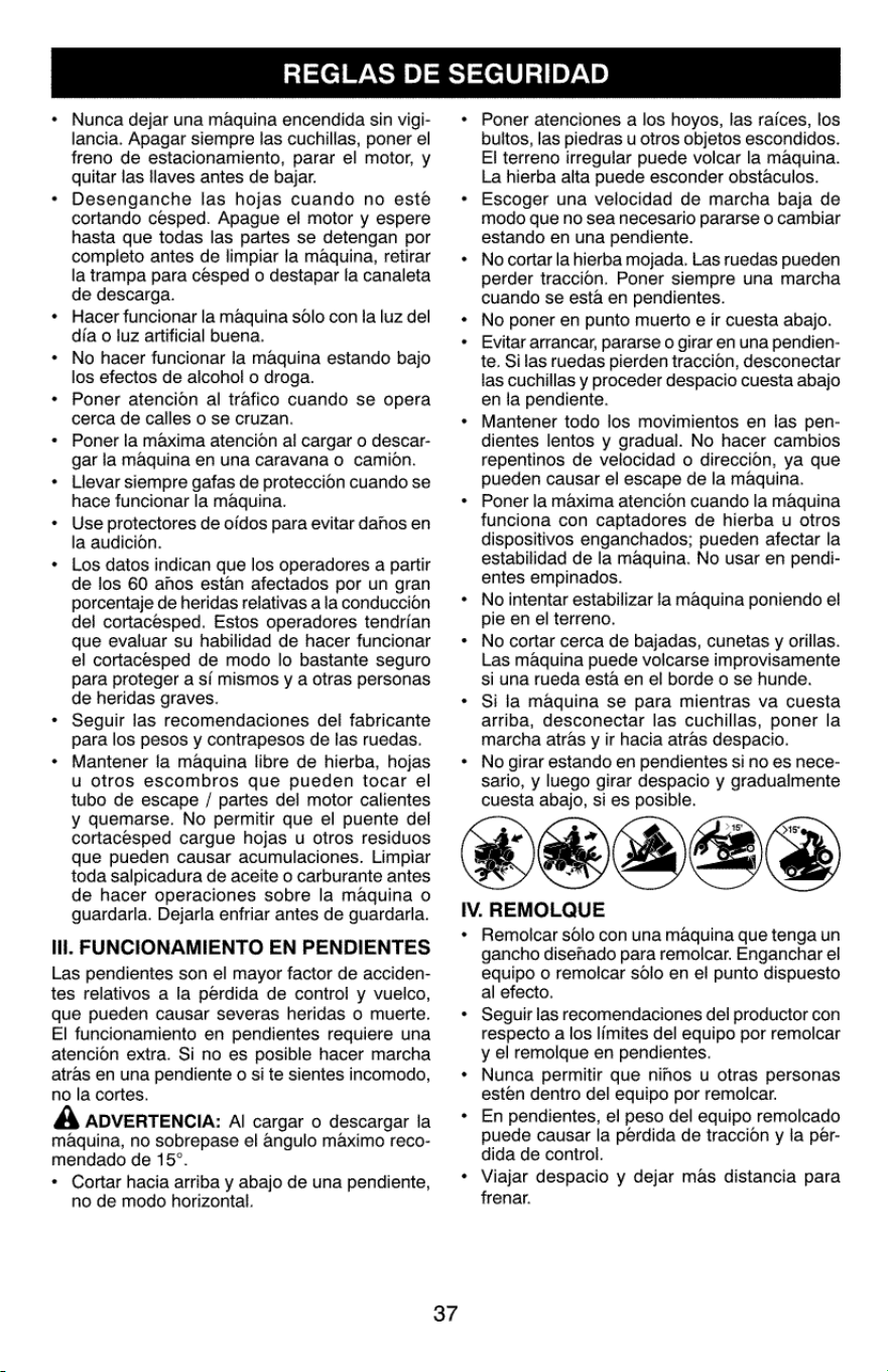
Nunca
dejar
una
maquina
encendida
sin vigi-
lancia.
Apagar
siempre
jas
cuchillas,
poner
el
freno
de
estacionamiento,
parar
el
motor,
y
quitar
las
llaves
antes
de
bajar.
Desenganche
las
hojas
cuando
no
esté
cortando
cesped.
Apague
el
motor
y
espere
hasta
que
todas
las
partes
se
detengan
por
completo
antes
de
limpiar
la
maquina,
retirar
la
tampa
para
césped
o
destapar
la
canaleta
de
descarga.
Hacer
funcionar
la
maquina
solo
con
ia
luz
del
dia
0
luz artificial
buena.
No
hacer
funcionar
la
maquina
estando
bajo
los
efectos
de
alcohol
o
droga.
Poner
atencion
al
trafico
cuando
se
opera
cerca
de
calles
o
se
cruzan.
Poner
la
maxima
atencion
al
cargar
o
descar-
gar
la
maquina
en
una
caravana
o
camion.
Llevar
siempre
gafas
de
proteccion
cuando
se
hace
funcionar
la
maquina.
Use
protectores
de
oidos
para
evitar
dahos
en
la
audicion.
Los
datos
indican
que
los
operadores
a
partir
de
los
60
ahos
estan
afectados
por
un
gran
porcentaje
de
heridas
relativas
ala
conduccion
del
cortacesped.
Estos
operadores
tendrian
que
evaluar
su
habilidad
de
hacer
funcionar
el
cortacesped
de
modo
lo
bastante
seguro
para
proteger
a
si
mismos
y
a
otras
personas
de
heridas graves.
Seguir
las
recomendaciones
del
fabricante
para
los
pesos
y
contrapesos
de
las
ruedas.
Mantener
la
maquina
libre
de
hierba,
hojas
u
otros
escombros
que
pueden
tocar
el
tubo
de
escape
/
partes
del
motor
calientes
y
quemarse.
No
permitir
que
el
puente
del
cortacesped
cargue
hojas
u
otros
residuos
que
pueden
causar
acumulaciones.
Limpiar
toda
salpicadura
de
aceite
o
carburante
antes
de
hacer
operaciones
sobre
la
maquina
o
guardarla.
Dejarla
enfriar
antes
de
guardarla.
li.
FUNCIONAMIENTO
EN
PENDIENTES
Las
pendientes
son
el
mayor
factor
de
acciden-
tes
relativos
a
la
perdida
de
contro!
y
vuelco,
que
pueden
causar
severas
heridas
o
muerte.
El
funcionamiento
en
pendientes
requiere
una
atencion
extra.
Si
no
es
posible
hacer
marcha
atras
en
una
pendiente
o
si
te
sientes
incomodo,
no
la
cortes.
A
ADVERTENCIA:
Al
cargar
o
descargar
la
maquina,
no
sobrepase
el
angulo
maximo
reco-
mendado
de
15°.
*
Cortar
hacia
arriba
y
abajo
de
una
pendiente,
no
de
modo
horizontal.
37
Poner
atenciones
a
los
hoyos,
las
raices,
los
bultos,
las
piedras
u
otros
objetos
escondidos.
El
terreno
irregular
puede
volcar
la
maquina.
La
hierba
alta
puede esconder
obstaculos.
Escoger
una
velocidad
de
marcha
baja
de
modo
que
no
sea
necesario
pararse
o
cambiar
estando
en
una
pendiente.
No
cortar
la
hierba
mojada.
Las
ruedas
pueden
perder
traccion.
Poner
siempre
una
marcha
cuando
se
esta
en
pendientes.
No
poner
en
punto
muerto
e
ir
cuesta
abajo.
Evitar
arrancar,
pararse
o
girar
en
una
pendien-
te.
Silas
ruedas
pierden
traccion,
desconectar
las
cuchillas
y
proceder
despacio
cuesta
abajo
en
la
pendiente.
Mantener
todo
los
movimientos
en
las
pen-
dientes
lentos
y
gradual. No
hacer
cambios
repentinos
de
velocidad
o
direccion,
ya
que
pueden
causar
el
escape
de
la
maquina.
Poner
la
maxima
atencion
cuando
la
maquina
funciona
con
captadores
de
hierba
u
otros
dispositivos
enganchados;
pueden
afectar
la
estabilidad
de
la
maquina.
No
usar
en
pendi-
entes
empinados.
No
intentar
estabilizar
la
maquina
poniendo
el
pie
en
el
terreno.
No
cortar
cerca
de
bajadas,
cunetas
y
orillas.
Las
maquina
puede
volcarse
improvisamente
si
una
rueda
esta
en
el
borde
o
se
hunde.
Si
la
maquina
se
para
mientras
va
cuesta
arriba,
desconectar
las
cuchillas,
poner
la
marcha
atras
y
ir
hacia
atras
despacio.
No
girar
estando
en
pendientes
si
no
es
nece-
sario,
y
luego
girar
despacio
y
graduaimente
cuesta
abajo,
si
es
posible.
IV.
REMOLQUE
e
Remoicar
solo
con
una
maquina
que
tenga
un
gancho
disehado
para
remoicar.
Enganchar
el
equipo
o
remolcar
solo
en
el
punto
dispuesto
al
efecto.
Seguir
las
recomendaciones
del
productor
con
respecto
a
los
limites
del
equipo
por
remolcar
y
el
remolque
en
pendientes.
Nunca
permitir
que
ninos
u
otras
personas
esten
dentro
del
equipo
por
remoicar.
En
pendientes,
el
peso
del
equipo
remolcado
puede
causar
la
pérdida
de
traccion
y
la
per-
dida
de
control.
Viajar
despacio
y
dejar
mas
distancia
para
frenar.
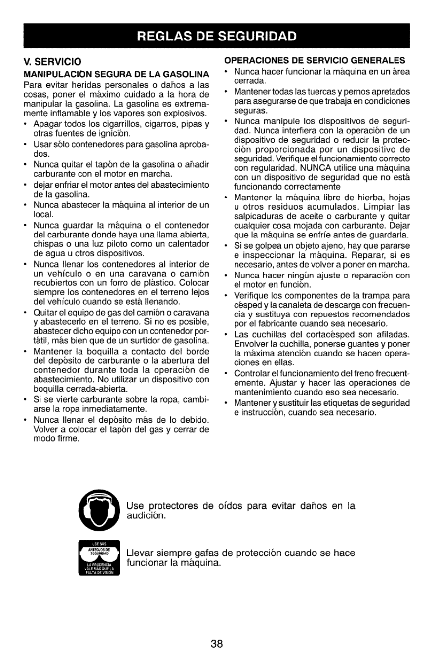
REGLAS
DE
SEGURIDAD
OPERACIONES
DE
SERVICIO
GENERALES
V.
SERVICIO
MANIPULACION
SEGURA
DE LA
GASOLINA
Para
evitar
heridas
personales
o
dahos
a
las
cosas,
poner
el
maximo
cuidado
a
la
hora
de
manipular
la
gasolina.
La
gasolina
es
extrema-
mente
inflamable
y
ios
vapores
son
explosivos.
*
Apagar
todos
los
cigarrillos,
cigarros,
pipas
y
otras
fuentes
de
ignicion.
+
Usar
solo
contenedores
para
gasolina
aproba-
dos.
+
Nunca
quitar
el
tapon
de
la
gasolina
o
ahadir
carburante
con
el
motor
en
marcha.
+
dejar
enfriar
el
motor
antes
del
abastecimiento
de
la
gasolina.
*
Nunca
abastecer
la
maquina
al
interior
de
un
local.
*
Nunca
guardar
la
maquina
o
el
contenedor
del
carburante
donde
haya
una
llama
abierta,
chispas
o
una
luz
piloto
como
un
calentador
de
agua
u
otros
dispositivos.
*
Nunca
llenar
jos
contenedores
al
interior
de
un
vehiculo
o
en
una
caravana
o
camion
recubiertos
con
un
forro
de
plastico.
Colocar
siempre
los
contenedores
en
el
terreno
lejos
del
vehiculo
cuando
se
esta
llenando.
*
Quitar
el
equipo
de
gas
del
camion
o
caravana
y
abastecerlo
en
el
terreno.
Si
no
es
posible,
abastecer
dicho
equipo
con
un
contenedor
por-
tatil,
mas
bien
que
de
un
surtidor
de
gasolina.
+
Mantener
la
boquilla
a
contacto
del
borde
del
depdsito
de
carburante
o la
abertura
del
contenedor
durante
toda
la
operacion
de
abastecimiento.
No
utilizar
un
dispositivo
con
boquilla
cerrada-abierta.
*
Si
se
vierte
carburante
sobre
la
ropa,
cambi-
arse
la
ropa
inmediatamente.
*
Nunca
llenar
el
deposito
mas
de
lo
debido.
Volver
a
colocar
el
tapon
del
gas
y
cerrar
de
modo
firme.
Nunca
hacer
funcionar
la
maquina
en un
area
cerrada.
Mantener
todas
las
tuercas
y
pernos
apretados
para
asegurarse
de
que
trabaja
en
condiciones
seguras.
Nunca
manipule
los
dispositivos
de
seguri-
dad.
Nunca
interfiera
con
la
operacion
de
un
dispositivo
de
seguridad
o
reducir
la
protec-
cion
proporcionada
por
un
dispositivo
de
seguridad.
Verifique
el
funcionamiento
correcto
con
regularidad.
NUNCA
utilice
una
maquina
con
un
dispositivo
de
seguridad
que
no
esta
funcionando
correctamente
Mantener
la
maquina
libre
de
hierba,
hojas
u
otros
residuos
acumulados.
Limpiar
las
salpicaduras
de
aceite
o
carburante
y
quitar
cualquier
cosa
mojada
con
carburante.
Dejar
que
la
maquina
se
entrie
antes
de
guardarla.
Si
se
golpea
un
objeto
ajeno,
hay
que
pararse
e
inspeccionar
la
maquina.
Reparar,
si
es
necesario,
antes
de
volver
a
poner
en
marcha.
Nunca
hacer
ningin
ajuste
o
reparacion
con
el
motor
en
funcion.
Verifique
los
componentes
de
la
trampa
para
cesped
y
la
canaleta
de
descarga
con
frecuen-
cia
y
sustituya
con
repuestos
recomendados
por
el
fabricante
cuando
sea
necesario.
Las
cuchillas
del
cortacesped
son
afiladas.
Envolver
la
cuchilla,
ponerse
guantes
y
poner
la
maxima
atencion
cuando
se
hacen
opera-
ciones
en
ellas.
Controlar
el
funcionamiento
del
freno
frecuent-
emente.
Ajustar
y
hacer
las
operaciones
de
mantenimiento
cuando
eso
sea
necesario.
Mantener
y
sustituir
las
etiquetas
de
seguridad
e
instruccion,
cuando
sea
necesario.
Use
protectores
de
ofdos
para
evitar
dahos
en
la
audicion.
ey
Lievar
siempre
gafas
de
proteccion
cuando
se
hace
mfem@™
funcionar
la
maquina.
z
Peake
ee
ethetraisd
38
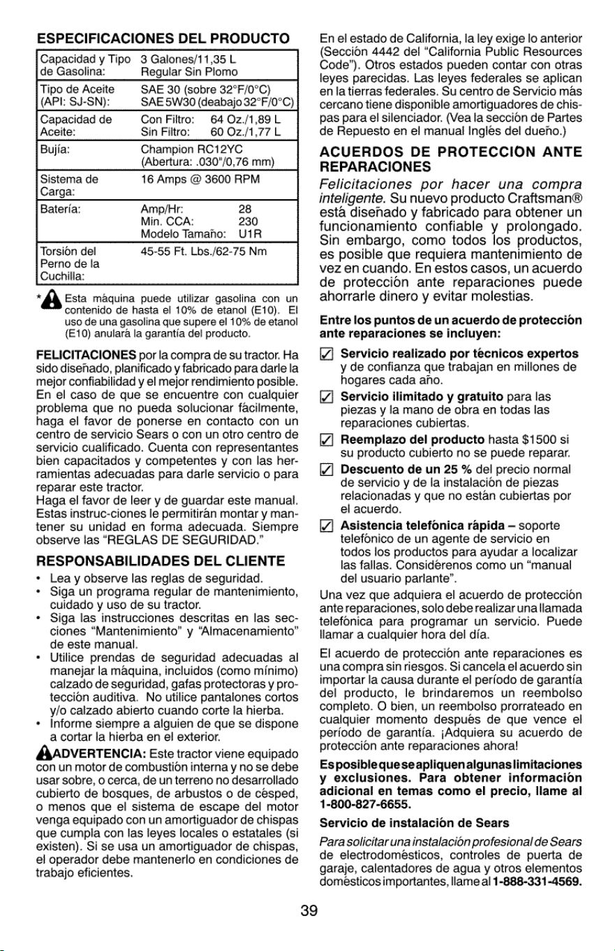
ESPECIFICACIONES
DEL
PRODUCTO
Capacidad
y
Tipo
3
Galones/11,35
L
de
Gasolina:
Regular
Sin
Plomo
Tipo
de
Aceite
SAE
30
(sobre
32°F/0°C)
(API:
SJ-SN):
SAE
5W30
(deabajo
32°F/0°C)
Capacidad
de
Con
Filtro:
64
02z./1,89L
Aceite:
Sin
Filtro:
60
02z./1,77L
Bujia:
Champion
RC12YC
(Abertura:
.030°/0,76
mm)
Sistema
de
16
Amps
@
3600
RPM
Carga:
Bateria:
Amp/Hr:
28
Min.
CCA:
230
Modelo
Tamanho:
U1R
Torsion
del
45-55
Ft.
Los./62-75
Nm
Perno
de
ja
Cuchilla:
*
Esta
maquina
puede
utilizar
gasolina
con
un
contenido
de
hasta
el
10%
de
etanol
(E10).
El
uso
de
una
gasolina
que
supere
el
10%
de
etanol
(E10)
anulara
la
garantia
del
producto.
FELICITACIONES
por
la
compra
de
su
tractor.
Ha
sido
disenado,
planificado
y
fabricado
para
darle
la
mejor
confiabilidad
y
el
mejor
rendimiento
posible.
En
el
caso
de
que
se
encuentre
con
cualquier
problema
que
no
pueda
solucionar
facilmente,
haga
el
favor
de
ponerse
en
contacto
con
un
centro
de
servicio
Sears
0
con
un otro
centro
de
servicio
cualificado.
Cuenta
con
representantes
bien
capacitados
y
competentes
y
con
las
her-
ramientas
adecuadas
para
darle
servicio
o
para
reparar
este
tractor.
Haga
el
favor
de
leer
y
de
guardar
este
manual.
Estas
instruc-ciones
le
permitiran
montar
y
man-
tener
su
unidad
en
forma
adecuada.
Siempre
observe
las
“REGLAS
DE
SEGURIDAD.”
RESPONSABILIDADES
DEL
CLIENTE
Lea
y
observe
las
reglas
de
seguridad.
Siga
un
programa
regular
de
mantenimiento,
cuidado
y
uso
de
su
tractor.
Siga
las
instrucciones
descritas
en
las
sec-
ciones
“Mantenimiento”
y
“Aimacenamiento”
de
este
manual.
Utilice
prendas
de
seguridad
adecuadas
al
manejar
la
maquina,
incluidos
(como
minimo)
caizado
de
seguridad,
gafas
protectoras
y
pro-
teccion
auditiva.
No
utilice
pantalones
cortos
y/o
calzado
abierto
cuando
corte
fa
hierba.
Informe
siempre
a
alguien
de
que
se
dispone
a
cortar
la
hierba
en
el
exterior.
AADVERTENCIA:
Este
tractor
viene
equipado
con
un
motor
de
combustion
interna
y
no
se
debe
usar
sobre,
0
cerca,
de
un
terreno
no
desarrollado
cubierto
de
bosques,
de
arbustos
o
de
césped,
©
menos
que
ei
sistema
de
escape
del
motor
venga equipado
con
un
amortiguador
de
chispas
que
cumpla
con
las
leyes
locales
o
estatales
(si
existen).
Si
se
usa
un
amortiguador
de
chispas,
el
operador
debe
mantenerlo
en
condiciones
de
trabajo
eficientes.
39
En
el
estado
de
California,
la
ley
exige
lo
anterior
(Seccion
4442
del
“California
Public
Resources
Code”).
Otros
estados
pueden
contar
con
otras
leyes
parecidas.
Las
leyes
federales
se
aplican
en
la
tierras
federales.
Su
centro
de
Servicio
mas
cercano
tiene
disponible
amortiguadores
de
chis-
pas
para
el
silenciador.
(Vea
la
seccion
de
Partes
de
Repuesto
en
el
manual
Ingles
del
dueho.)
ACUERDOS
DE
PROTECCION
ANTE
REPARACIONES
Felicitaciones
por
hacer
una
compra
inteligente.
Su
nuevo
producto
Craftsman®
esta
disehado
y
fabricado
para
obtener
un
funcionamiento
confiable
y
prolongado.
Sin
embargo,
como
todos
los
productos,
es
posible
que requiera
mantenimiento
de
vez
en
cuando.
En
estos
casos,
un
acuerdo
de
proteccion
ante
reparaciones
puede
ahorrarle
dinero
y
evitar
molestias.
Entre
los
puntos
de un
acuerdo
de
proteccion
ante
reparaciones
se
incluyen:
Servicio
realizado
por
tecnicos
expertos
y
de
confianza
que
trabajan
en
millones
de
hogares
cada
ano.
Servicio
ilimitado
y
gratuito
para
las
piezas
y
la
mano
de
obra
en
todas
las
reparaciones
cubiertas.
Reemplazo
del
producto
hasta
$1500
si
su
producto
cubierto
no
se
puede
reparar.
Descuento
de un
25
%
del
precio
normal
de
servicio
y
de
fa
instalacion
de
piezas
relacionadas
y
que
no
estan
cubiertas
por
el
acuerdo.
Asistencia
telefonica
rapida
—
soporte
telefonico
de
un
agente
de
servicio
en
todos
los
productos
para
ayudar
a
localizar
las
fallas.
Considerenos
como
un
“manual
del
usuario
parlante”.
Una
vez
que
adquiera
el
acuerdo
de
proteccion
ante
reparaciones,
solo
debe
realizar
unallamada
telefonica para
programar
un
servicio.
Puede
llamar
a
cualquier
hora
del
dia.
El
acuerdo
de
proteccion
ante
reparaciones
es
una
compra
sin
riesgos.
Si
cancela
el
acuerdo
sin
importar
la
causa
durante
el
periodo
de
garantia
del
producto,
le
brindaremos
un
reembolso
completo.
O
bien,
un
reembolso
prorrateado
en
cualquier
momento
despues
de
que
vence
el
periodo
de
garantia.
jAdquiera
su
acuerdo
de
proteccion
ante
reparaciones
ahora!
Es
posible quese
apliquenalgunaslimitaciones
y
exclusiones.
Para
obtener
informacion
adicional
en
temas
como
el
precio,
llame
al
1-800-827-6655.
Servicio
de
instalacion
de
Sears
Para
solicitar
una
instalacion
profesional
de
Sears
de
electrodomésticos,
controles
de
puerta
de
garaje,
calentadores
de
agua
y
otros
elementos
domesticos
importantes,
llame
al
1-888-331-4569.
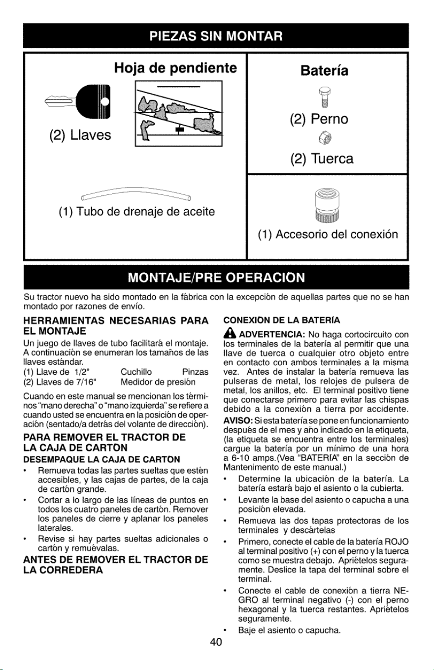
PIEZAS
SIN
MONTAR
Hoja
de
pendiente
(2)
Llaves
(1)
Tubo
de
drenaje
de
aceite
Bateria
Fi
(2)
Perno
@
(2)
Tuerca
(1)
Accesorio
del
conexién
MONTAJE/PRE
OPERACION
Su
tractor
nuevo
ha
sido
montado
en
la
fabrica
con
la
excepcion
de
aquellas
partes
que
no
se
han
montado
por
razones
de
envio.
HERRAMIENTAS
NECESARIAS
PARA
EL
MONTAJE
Un
juego
de
llaves
de
tubo
facilitara
el
montaje.
A
continuacion
se
enumeran
los
tamanos
de
las
llaves
estandar.
(1)
Uave
de
1/2"
(2)
Llaves
de
7/16"
Cuando
en
este
manual
se
mencionan
los
termi-
nos
“mano
derecha’
o
“mano
izquierda’
se
refiere
a
cuando
usted
se
encuentra
en
la
posicion
de
oper-
acion
(sentado/a
detras
del
volante
de
direccion).
PARA
REMOVER
EL
TRACTOR
DE
LA
CAJA
DE
CARTON
DESEMPAQUE
LA
CAJA
DE
CARTON
Remueva
todas
las
partes
sueltas
que
estén
accesibles,
y
las
cajas
de
partes,
de
la
caja
de
carton
grande.
Cortar
a
lo
largo
de
las
lineas
de
puntos
en
todos
los
cuatro
paneles
de
carton.
Remover
los
paneles
de
cierre
y
aplanar
los
paneles
laterales.
Revise
si
hay
partes
sueltas
adicionales
o
carton
y
remuevalas.
ANTES
DE
REMOVER
EL
TRACTOR
DE
LA
CORREDERA
Cuchillo
Pinzas
Medidor
de
presion
40
CONEXION
DE
LA
BATERIA
A
ADVERTENCIA:
No
haga
cortocircuito
con
los
terminales
de
la
baterfa
al
permitir
que una
lave
de
tuerca
o
cualquier
otro
objeto
entre
en
contacto
con
ambos
terminales
a
la
misma
vez.
Antes
de instalar
la
bateria
remueva
las
pulseras
de
metal,
los
relojes
de
pulsera
de
metal,
los
anillos,
etc.
El
terminal
positivo
tiene
que
conectarse
primero
para
evitar
las
chispas
debido
a
la
conexion
a
tierra
por
accidente.
AVISO:
Siesta
bateria
se
pone
en
funcionamiento
después
de
el
mes
y
ano
indicado
en
la
etiqueta,
(la
etiqueta
se
encuentra
entre
los
terminales)
cargue
la
bateria
por
un
minimo
de
una
hora
a
6-10
amps.(Vea
“BATERIA’
en
la
seccion
de
Mantenimento
de
este
manual.)
Determine
!a
ubicacioOn
de
la
baterfa.
La
baterfa
estara
bajo
el
asiento
o
la
cubierta.
Levante
la
base
del
asiento
o
capucha
a
una
posicion
elevada.
Remueva
las
dos
tapas
protectoras
de
los
terminales
y
descartelas
Primero,
conecte
el
cable
de
la
bateria
ROJO
al
terminal
positivo
(+)
con
el
perno
y
la
tuerca
como
se
muestra
debajo.
Apriételos
segura-
mente.
Deslice
la
tapa
del
terminal
sobre
el
terminal.
Conecte
el
cable
de
conexion
a
tierra
NE-
GRO
al
terminal
negativo
(-)
con
el
perno
hexagonal
y la
tuerca
restantes.
Aprietelos
seguramente.
Baje
el
asiento
o
capucha.
.
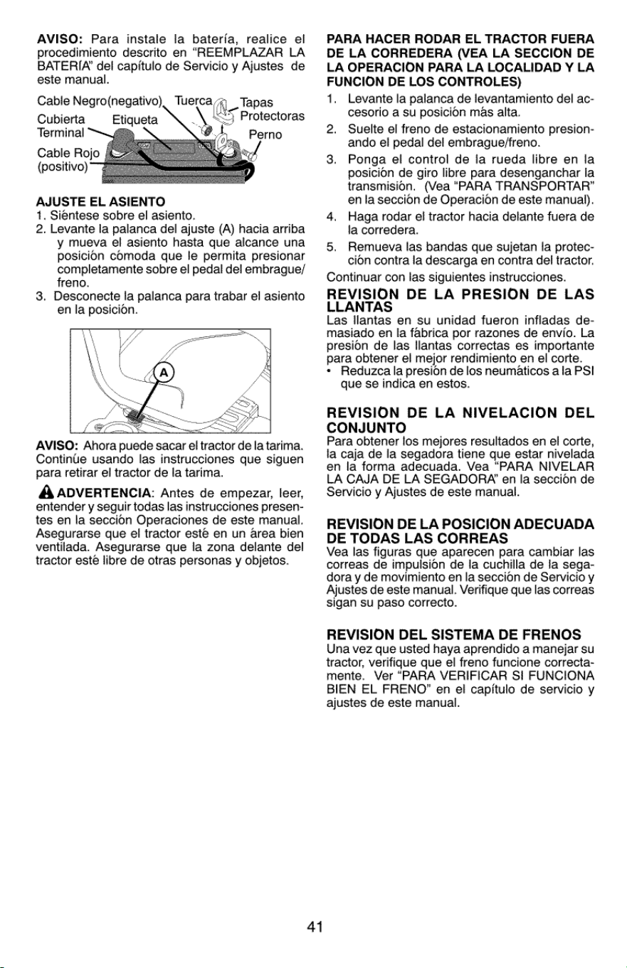
AVISO:
Para
instale
la
baterfa,
realice
el
procedimiento
descrito
en
“REEMPLAZAR
LA
BATERIA’
del
capitulo
de
Servicio
y
Ajustes
de
este
manual.
SV
Cable
Negro(negativo)
Tapas
Protectoras
Cubierta
Etiqueta
2
Terminal
(
Perno
Cable
Rojo
(positive)
AJUSTE
EL
ASIENTO
1.
Sientese
sobre
el
asiento.
2,
Levante
la
palanca
del
ajuste
(A)
hacia
arriba
y
mueva
el
asiento
hasta
que
alcance
una
posicion
comoda
que
le
permita
presionar
completamente
sobre
el
pedal
del
embrague/
freno.
.
Desconecte
la
palanca
para
trabar
el
asiento
en
la
posicion.
AVISO:
Ahora
puede
sacar
el
tractor
de
la
tarima.
Continue
usando
las
instrucciones
que
siguen
para
retirar
el
tractor
de
la
tarima.
A
ADVERTENCIA:
Antes
de
empezar,
leer,
entender
y
sequir
todas
las
instrucciones
presen-
tes
en
la
seccion
Operaciones
de
este
manual.
Asegurarse
que
el
tractor
esté
en
un
area
bien
ventilada.
Asegurarse
que
la
zona
delante
dei
tractor
este
libre
de
otras
personas
y
objetos.
At
PARA
HACER
RODAR
EL
TRACTOR
FUERA
DE
LA
CORREDERA
(VEA
LA
SECCION
DE
LA
OPERACION
PARA
LA
LOCALIDAD
Y
LA
FUNCION
DE
LOS
CONTROLES)
1.
Levante
la
palanca
de
levantamiento
del
ac-
cesorio
a
su
posicion
mas
alta.
Suelte
el
freno
de
estacionamiento
presion-
ando
el
pedal
del
embrague/freno.
Ponga
el
control
de
fa
rueda
libre
en
la
posicion
de
giro
libre
para
desenganchar
la
transmision.
(Vea
“PARA
TRANSPORTAR”
en
la
seccion
de
Operacion
de
este
manual).
Haga
rodar
el
tractor
hacia
delante
fuera
de
la
corredera.
Remueva
las
bandas
que
sujetan
fa
protec-
cion
contra
la
descarga
en
contra
del
tractor.
Continuar
con
las
siguientes
instrucciones.
REVISION
DE LA
PRESION
DE
LAS
LLANTAS
Las
llantas
en
su
unidad
fueron
infladas
de-
masiado
en
la
fabrica
por
razones
de
envio.
La
presion
de
las
llantas
correctas
es
importante
para
obtener
el
mejor
rendimiento
en
el
corte.
*
Reduzca
la
presion
de
los
neumaticos
ala
PSI
que
se
indica
en
estos.
2.
3.
4.
5.
REVISION
DE
LA
NIVELACION
DEL
CONJUNTO
Para
obtener
los
mejores
resultados
en
el
corte,
la
caja
de
la
segadora
tiene
que
estar
nivelada
en
la
forma
adecuada.
Vea
“PARA
NIVELAR
LA
CAJA
DE
LA
SEGADORA’
en
Ia
seccion
de
Servicio
y
Ajustes
de
este
manual.
REVISION
DE LA
POSICION
ADECUADA
DE
TODAS
LAS
CORREAS
Vea
las
figuras
que
aparecen
para
cambiar
las
correas
de
impulsion
de
la
cuchilla
de
la
sega-
dora
y
de
movimiento
en
la
seccion
de
Servicio
y
Ajustes
de
este
manual.
Verifique
que
las
correas
sigan
su
paso
correcto.
REVISION
DEL
SISTEMA
DE
FRENOS
Una
vez
que
usted
haya
aprendido
a
manejar
su
tractor,
verifique
que
el
freno
funcione
correcta-
mente.
Ver
“PARA
VERIFICAR
SI
FUNCIONA
BIEN
EL
FRENO”
en
el
capitulo
de
servicio
y
ajustes
de
este
manual.
Jf
LISTA
DE
REVISION
Antes
de
operar
y
de
disfrutar
de
su
tractor
nuevo,
le
deseamos
que
reciba
el
mejor
rendimiento
y la
mayor
satisfaccion
de
este
producto
de
calidad.
Haga
el
favor
de
revisar
la
lista
a
continuacion:
/
Se
han
completado
todas
las
instrucciones
de
montaje.
/
No
quedan
partes
sueltas
en
la
caja
de
carton.
v
Labateria
esta
preparada
y
cargada
en
forma
adecuada.
/
Elasiento
ha
sido
ajustado
en
forma
comoda
y
apretado
en
forma
segura.
/
Todas
las
llantas
han
sido
infladas
en
forma
adecuada.
(Para
fines
de
envio,
las
llantas
se
inflaron
demasiado
en
la
fabrica.)
AsegUirese
que
el
conjunto
segador
este
nivelado
en
forma
adecuada,
de
lado
a
lado
y
desde
adelante
hacia
atras,
para
obtener
los
mejores
resultados
en
el
corte.
(Las
llantas
tienen
que
estar
infladas
en
forma
adecuada
para
la
nivelacion.)
Revise
las
correas
de
impulsion
y
de
la
segadora.
Aseglirese
que
recorran
el
paso
adecuado
alrededor
de
las
poleas
y
dentro
de
todos
los
fijadores
de
las
correas.
/
Revise
el
alambrado.
Fijese
que
todas
las
conexiones
todavia
estén
seguras
y
que
los
alambres
estén sujetos
en
forma
adecuada.
/
Antes
de
conducir
el
tractor,
asegurese
que
el
control
de
rueda
libre
este
en
la
posicion
de
“transmision
enganchada”
(Vea
“PARA
TRANSPORTAPR’
en
la
seccion
de
la
Oper-
acion
de
este
manual).
Al
mismo
tiempo
que
aprende
a
como
usar
su
tractor,
preste
atencion
extra
a
los
puntos
de
importancia
que
se
presentan
a
continuacion:
/
El
aceite
del
motor
tiene
que
ilegar
al
nivel
adecuado.
El
estanque
de
combustible
tiene
que
estar
lleno
con
gasolina
sin
plomo
regular,
nueva
y
limpia.
Familiaricese
con
todos
los
controles
—
su
ubicacion
y
su
funcion.
Opeérelos
antes
de
hacer
arrancar
el
motor.
Jv
Asegurese
que
el
sistema
de
frenos
esté
en
una
condicion
de
operacion
segura.
Asegurarse
de
que
el
Sistema
de
Presencia
del
Operador
y
el
Sistema
de
Funcionamiento
Atras
(ROS)
funcionan
de
modo
adecuado
(Ver
las
Secciones
de
Funcionamiento
y
Mantenimiento
en
este
manual).
Es
importante
purgar
la
transmision
antes
de
operar
su
tractor
por
la
primera
vez.
Siga
las
instrucciones
adecuadas
para
el
empiezo
y
para
purgar
(Vea
“PARA
EMPEZAR
EL
MO-
TOR’
y
“PARA
PURGAR
LA
TRANSMISION”
enla
seccion
de
la
Operacion
de
este
manual).
42
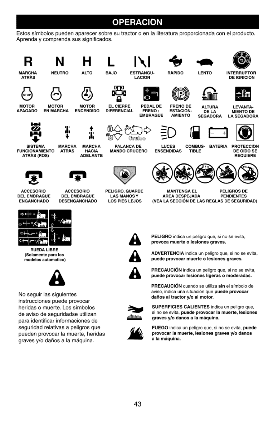
OPERACION
Estos
simbolos
pueden
aparecer
sobre
su
tractor
o
en
la
literatura
proporcionada
con
el
producto.
Aprenda
y
comprenda
sus
significados.
R
WN
4H
MARCHA
NEUTRO
ALTO
ATRAS
MOTOR
MOTOR MOTOR
APAGADO
ENMARCHA
ENCENDIDO
HH
@
1
4
+
+
SISTEMA
MARCHA MARCHA
FUNCIONAMIENTO
ATRAS
HACIA
ATRAS
(ROS)
ADELANTE
2 =
ACCESORIO ACCESORIO
DEL
EMBRAGUE
DEL
EMBRAGUE
ENGANCHADO
DESENGANCHADO
RUEDA
LIBRE
(Solamente
para
ios
modelos
automatico)
A
No
seguir
las
siguientes
instrucciones
puede
provocar
heridas
o
muerte.
Los
simbolos
de
aviso
de
seguridadse
utilizan
para
identificar
informaciones
de
seguridad
relativas
a
peligros
que
pueden
provocar
la
muerte,
heridas
graves
y/o
dafios
a
la
maquina.
L
Wl
@
-™
BAJO
ESTRANGU-
RAPIDO
LENTO
INTERRUPTOR
LACION
DE
IGNICION
ie,
je
iP
a
©
i
FE
EL
CIERRE
PEDAL
DE
FRENO
DE
ALTURA
LEVANTA-
DIFERENCIAL
FRENO
/
ESTACION-
DELA
MIENTO
DE
EMBRAGUE
AMIENTO
SEGADORA
LASEGADORA
—
BA
E>
=
me
=
Cruise
_
PALANCA
DE
LUCES
COMBUS-
BATERIA
PROTECCION
MANDO
CRUCERO
ENSENDIDAS
‘TIBLE
DE
OIDO
SE
REQUIERE
PELIGRO,
GUARDE
MANTENGA
EL
PELIGROS
DE
LAS
MANOSY
AREA
DESPEJADA
PENDIENTES
LOS
PIES
LEJOS
(VEA
LA
SECCION
DE
LAS
REGLAS
DE
SEGURIDAD)
PELIGRO
indica
un
peligro
que,
si
no
se
evita,
provoca
muerte
o
lesiones
graves.
ADVERTENCIA
indica
un
peligro
que,
si
no se
evita,
puede
provocar
muerte
o
lesiones
graves.
PRECAUCION
indica
un
peligro que,
si
no
se
evita,
puede
provocar
lesiones
ligeras
o
moderadas.
PRECAUCION
cuando
se
utiliza
sin
el
simbolo
de
aviso,
indica
una
situacién
que
puede
provocar
dafios
al
tractor
y/o
al
motor.
SUPERFICIES
CALIENTES
indica
un
peligro
que,
si
no
se
evita,
puede
provocar
la
muerte,
lesiones
graves
y/o
danos
a la
maquina.
A
A
A
aa
anliinbtin,
—
K
FUEGO
indica
un
peligro
que,
si
no se
evita,
puede
ly
provocar
la
muerte,
lesiones
graves
y/o
danos
a
la
maquina.
~
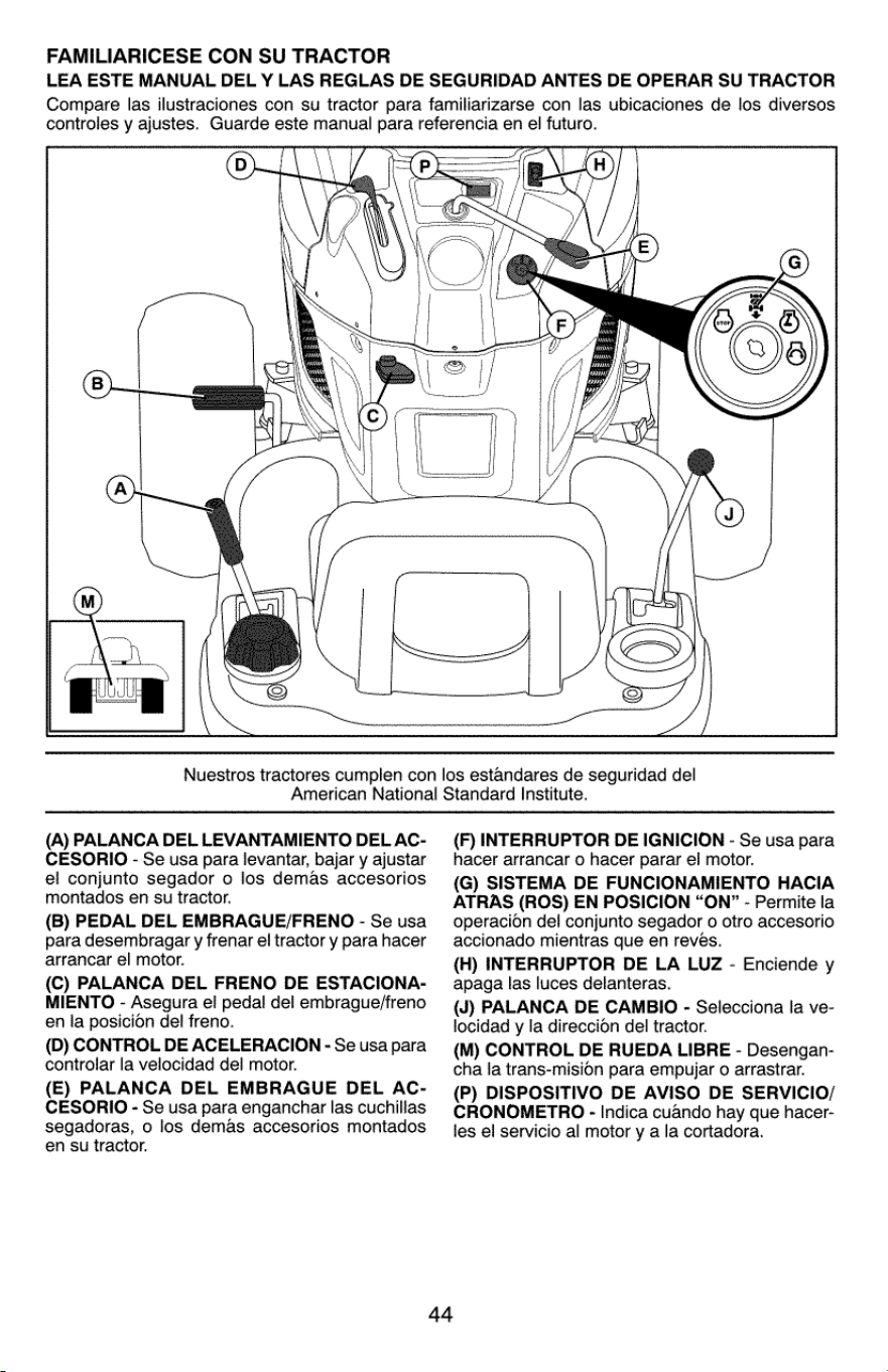
FAMILIARICESE
CON
SU
TRACTOR
LEA
ESTE
MANUAL
DEL
Y
LAS
REGLAS
DE
SEGURIDAD
ANTES
DE
OPERAR
SU
TRACTOR
Compare
las
ilustraciones
con
su
tractor
para
familiarizarse
con
las
ubicaciones
de
los
diversos
controles
y
ajustes.
Guarde
este
manual
para
referencia
en
el
futuro.
Nuestros
tractores
cumplen
con
los
estandares
de
seguridad
del
American
National
Standard
Institute.
(A)
PALANCA
DEL
LEVANTAMIENTO
DEL
AC-
CESORIO
-
Se
usa para
levantar,
bajar
y
ajustar
el
conjunto
segador
o
los
demas
accesorios
montados
en
su
tractor.
(B)
PEDAL
DEL
EMBRAGUE/FRENO
-
Se
usa
para
desembragar
y
frenar
el
tractor
y
para
hacer
arrancar
el
motor.
(C)
PALANCA
DEL
FRENO
DE
ESTACIONA-
MIENTO
-
Asegura
el
pedai
del
embrague/freno
en
la
posicion
del
freno.
(D)
CONTROL
DE
ACELERACION
-
Se
usa
para
controlar
la
velocidad
del
motor.
(E)
PALANCA
DEL
EMBRAGUE
DEL
AC-
CESORIO
-
Se
usa
para
enganchar
las
cuchillas
segadoras,
o
los
demas
accesorios
montados
en
su
tractor.
(F)
INTERRUPTOR
DE
IGNICION
-
Se
usa para
hacer
arrancar
o
hacer
parar
ej
motor.
(G)
SISTEMA
DE
FUNCIONAMIENTO
HACIA
ATRAS
(ROS)
EN
POSICION
“ON”
-
Permite
la
operacion
del
conjunto
segador
0
otro
accesorio
accionado
mientras
que
en
reves.
(H)
INTERRUPTOR
DE
LA
LUZ
-
Enciende
y
apaga
las
luces
delanteras.
(J)
PALANCA
DE
CAMBIO
-
Selecciona
la
ve-
locidad
y
la
direccion
del
tractor.
(M)
CONTROL
DE
RUEDA
LIBRE
-
Desengan-
cha
la
trans-mision
para
empujar
o
arrastrar.
(P)
DISPOSITIVO
DE
AVISO
DE
SERVICIO/
CRONOMETRO
-
Indica
cuando
hay
que
hacer-
les
el
servicio
al
motor
y
a
la
cortadora.
44
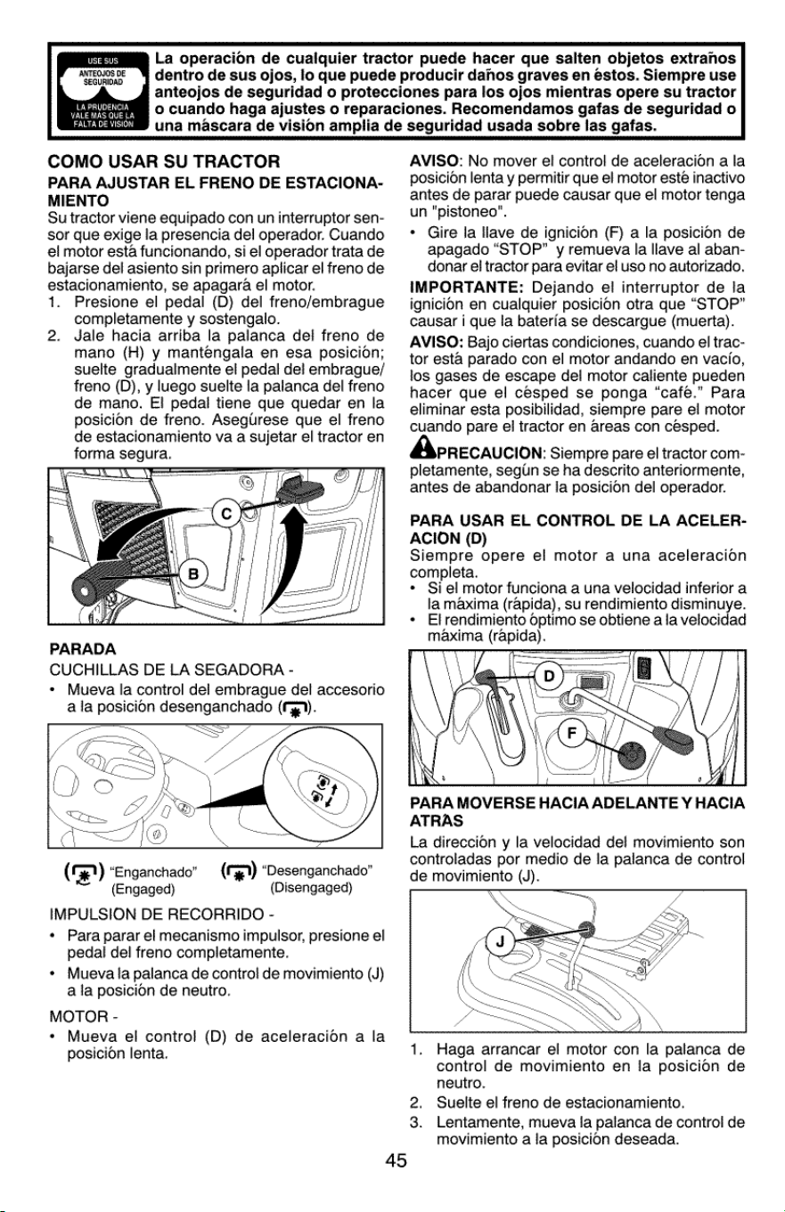
st
ces)
ANTEOQJOS
DE
SEGURIDAD
ees
VALE
MAS
QUE
LA
RSE
La
operacion
de
cualquier
tractor
puede
hacer que
salten
objetos
extranos
dentro
de
sus
ojos,
lo
que
puede
producir
dahos
graves
en
estos.
Siempre
use
anteojos
de
seguridad
o
protecciones
para
los
ojos
mientras
opere
su
tractor
o
cuando
haga
ajustes
o
reparaciones.
Recomendamos
gafas
de
seguridad
o
una
mascara
de
vision
amplia
de
seguridad
usada
sobre
las
gafas.
COMO
USAR
SU
TRACTOR
PARA
AJUSTAR
EL
FRENO
DE
ESTACIONA-
MIENTO
Su
tractor
viene
equipado
con
un
interruptor
sen-
sor
que
exige
la
presencia
del
operador.
Cuando
el
motor
esta
funcionando,
si
el
operador
trata
de
bajarse
del
asiento
sin
primero
aplicar
el
freno
de
estacionamiento,
se
apagara
el
motor.
1.
Presione
el
pedal
(D)
del
freno/embrague
completamente
y
sostengalo.
2.
Jale
hacia
arriba
la
palanca
del
freno
de
mano
(H)
y
mantengala
en
esa
posicion;
suelte
gradualmente
el
pedal
del
embrague/
freno
(D),
y
luego
suelte
la
palanca
del
freno
de
mano.
E!
pedal
tiene
que
quedar
en
la
posicion
de
freno.
Asegurese
que
el
freno
de
estacionamiento
va
a
sujetar
el
tractor
en
forma
segura.
\
PARADA
CUCHILLAS
DE
LA
SEGADORA
-
*
Mueva
la
control
del
embrague
del
accesorio
a
la
posicion
desenganchado
(yy.
am
ST
acs
Jo
on)
A
®
Qt
Sor
|
(Ge)
“Enganchado”
(Engaged)
IMPULSION
DE
RECORRIDO
-
«
Para
parar
el
mecanismo
impulsor,
presione
el
pedal
del
freno
completamente.
*
Mueva
la
palanca
de
control
de
movimiento
(J)
a
la
posicion
de
neutro.
MOTOR
-
+
Mueva
el
control
(D)
de
aceleracion
a
la
posicion
lenta.
(3)
“Desenganchado”
(Disengaged)
AVISO:
No
mover
el
control
de
aceleracion
ala
posicion
lenta
y
permitir
que
el
motor
este
inactivo
antes
de
parar
puede
causar
que
el
motor
tenga
un
"pistoneo".
*
Gire
la
llave
de
ignicion
(F)
a
la
posicion
de
apagado
“STOP”
y
remueva
la
llave
al
aban-
donar
el
tractor
para
evitar
el
uso
no
autorizado.
IMPORTANTE:
Dejando
el
interruptor
de
la
ignicion
en
cualquier
posicion
otra
que
“STOP”
causar
i
que
la
baterfa
se
descargue
(muerta).
AVISO:
Bajo
ciertas
condiciones,
cuando
el
trac-
tor
esta
parado
con
el
motor
andando
en
vacio,
los
gases
de
escape
dei
motor
caliente
pueden
hacer
que
el
cesped
se
ponga
“cafe.”
Para
eliminar
esta
posibilidad,
siempre
pare
el
motor
cuando
pare
el
tractor
en
areas
con
césped.
PRECAUCION:
Siempre
pare
el
tractor
com-
pletamente,
segin
se
ha
descrito
anteriormente,
antes
de
abandonar
Ia
posicion
del
operador.
PARA USAR
EL
CONTROL
DE LA
ACELER-
ACION
(D)
Siempre
opere
el
motor
a
una
aceleracion
completa.
*
Si
el
motor funciona
a
una
velocidad
inferior
a
la
maxima
(rapida),
su
rendimiento
disminuye.
*
Elrendimiento
optimo
se
obtiene
a
la
velocidad
maxima
(rapida).
PARA
MOVERSE
HACIA
ADELANTE
Y
HACIA
ATRAS
La
direccion
y
la
velocidad
del
movimiento
son
controladas
por
medio
de
la
palanca
de
control
de
movimiento
(J).
Haga
arrancar
el
motor
con
la
palanca
de
control
de
movimiento
en
la
posicion
de
neutro.
2.
Suelte
el
freno
de
estacionamiento.
3.
Lentamente,
mueva
ia
palanca
de
control
de
movimiento
a
la
posicion
deseada.
45
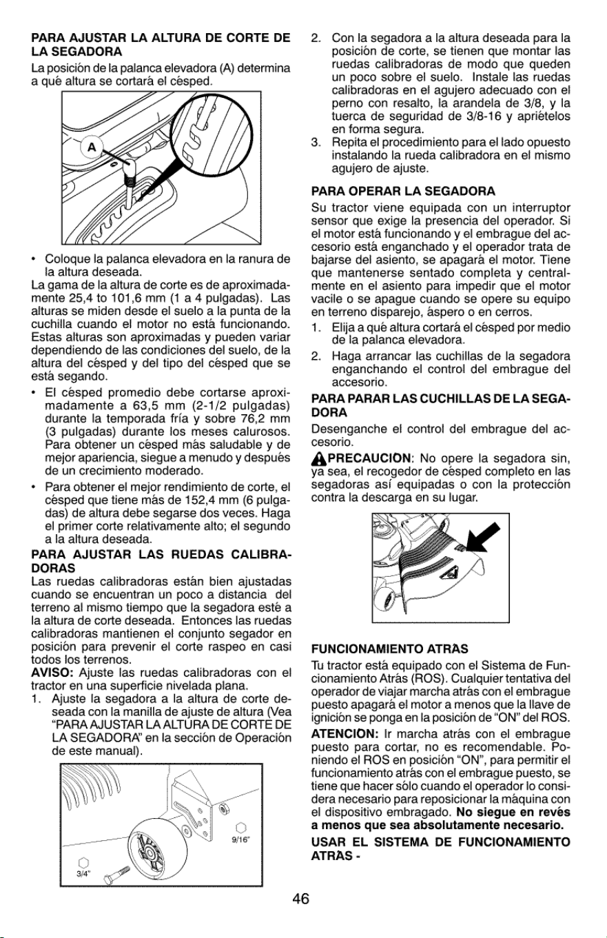
PARA
AJUSTAR
LA
ALTURA
DE
CORTE
DE
LA
SEGADORA
La
posicion
de
la
palanca
elevadora
(A)
determina
a
qué
altura
se
cortara
el
césped.
WS
*
Coloque
la
palanca
elevadora
en
la
ranura
de
la
altura
deseada.
La
gama
de
Ia
altura
de
corte
es
de
aproximada-
mente
25,4
to
101,6
mm
(1
a
4
pulgadas).
Las
alturas
se
miden
desde
el
suelo
a
la
punta
de
la
cuchilla
cuando
el
motor
no
esta
funcionando.
Estas
alturas
son
aproximadas
y
pueden
variar
dependiendo
de
las
condiciones
del
suelo,
de
la
altura
del
cesped
y
del
tipo
del
cesped
que
se
esta
segando.
El
cesped
promedio
debe
cortarse
aproxi-
madamente
a
63,5
mm
(2-1/2
pulgadas)
durante
la
temporada
fria
y
sobre
76,2
mm
(3
pulgadas)
durante
los
meses
calurosos.
Para
obtener
un
cesped
mas
saludable
y
de
mejor
apariencia,
siegue
a
menudo
y
despues
de
un
crecimiento
moderado.
Para
obtener
el
mejor
rendimiento
de
corte,
el
césped
que
tiene
mas
de
152,4
mm
(6
pulga-
das)
de
altura
debe
segarse
dos
veces.
Haga
el
primer
corte
relativamente
alto;
el
segundo
a
la
altura
deseada.
PARA
AJUSTAR
LAS
RUEDAS
CALIBRA-
DORAS
Las
ruedas
calibradoras
estan
bien
ajustadas
cuando
se
encuentran
un
poco
a
distancia
del
terreno
ai
mismo
tiempo
que
la
segadora
esté
a
la
altura
de
corte
deseada.
Entonces
las
ruedas
calibradoras
mantienen
el
conjunto
segador
en
posicion
para
prevenir
el
corte
raspeo
en
casi
todos
los
terrenos.
AVISO:
Ajuste
las
ruedas
calibradoras
con
el
tractor
en
una
superficie
nivelada
plana.
1.
Ajuste
la
segadora
a
la
altura
de
corte
de-
seada
con
la
manilla
de
ajuste
de
altura
(Vea
“PARA
AJUSTAR
LA
ALTURA
DE
CORTE
DE
LA
SEGADORA
en
la
seccion
de
Operacion
de
este
manual).
46
2.
Con
la
segadora
a
la
altura
deseada
para
la
posicion
de
corte,
se
tienen
que
montar
las
ruedas
calibradoras
de
modo
que
queden
un
poco
sobre
el
suelo.
Instale
las
ruedas
calibradoras
en
el
agujero
adecuado
con
el
perno
con
resalto,
la
arandela
de
3/8,
y la
tuerca
de
seguridad
de
3/8-16
y
apriételos
en
forma
segura.
Repita
el
procedimiento
para
el
lado
opuesto
instalando
la
rueda
calibradora
en
el
mismo
agujero
de
ajuste.
PARA
OPERAR
LA
SEGADORA
Su
tractor
viene
equipada
con
un
interruptor
sensor
que
exige
la
presencia
del
operador.
Si
el
motor
esta
funcionando
y
el
embrague
del
ac-
cesorio
esta
enganchado
y
el
operador
trata
de
bajarse
del
asiento,
se
apagara
el
motor.
Tiene
que
mantenerse
sentado
completa
y
central-
mente
en
el
asiento
para
impedir
que
el
motor
vacile
0
se
apague
cuando
se
opere
su
equipo
en
terreno
disparejo,
aspero
o
en
cerros.
1.
Elija
a
que
altura
cortara
el
cesped
por
medio
de
la
palanca
elevadora.
2.
Haga
arrancar
las
cuchillas
de
la
segadora
enganchando
el
control
del
embrague
del
accesorio.
PARA
PARAR
LAS
CUCHILLAS
DE LA
SEGA-
DORA
Desenganche
el
control
del
embrague
del
ac-
cesorio.
AAPRECAUCION:
No
opere
la
segadora
sin,
ya
sea,
el
recogedor
de
cesped
completo
en
las
segadoras
asi
equipadas
o
con
la
proteccion
contra
la
descarga
en
su
lugar.
FUNCIONAMIENTO
ATRAS
Tu
tractor
esta
equipado
con
el
Sistema
de
Fun-
cionamiento
Atras
(ROS).
Cualquier
tentativa
del
operador
de
viajar
marcha
atras
con
el
embrague
puesto
apagara
el
motor
a
menos
que
la
llave
de
ignicion
se
ponga
en
la
posicion
de
“ON”
del
ROS.
ATENCION:
Ir
marcha
atras
con
el
embrague
puesto
para
cortar,
no
es
recomendable.
Po-
niendo
el
ROS
en
posicion
“ON”, para
permitir
el
funcionamiento
atras
con
el
embrague
puesto,
se
tiene
que hacer
solo
cuando
el
operador
lo
consi-
dera
necesario
para
reposicionar
la
maquina
con
el
dispositivo
embragado.
No
siegue
en
reves
a
menos
que
sea
absolutamente
necesario.
USAR
EL
SISTEMA
DE
FUNCIONAMIENTO
ATRAS
-
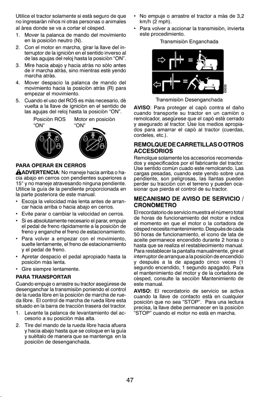
Utilice
el
tractor
solamente
si
esta
seguro
de
que
no
ingresaran
nihos
ni
otras
personas
o
animales
al
area
donde
se
va
a
cortar
el
cesped.
1.
Mover
ia
palanca
de
mando
del
movimiento
en
la
posicion
neutro
(N).
Con
el
motor
en
marcha,
girar
la
llave
del
in-
terruptor
de
la
ignicion
en
el
sentido
inverso
al
de
las
agujas
del
reloj
hasta
la
posicion
“ON”.
Mire
hacia
abajo
y
hacia
atras
no
sdlo
antes
de
ir
marcha
atras,
sino
mientras
este
yendo
marcha
atras.
Mover
despacio
la
palanca
de
mando
del
movimiento
hacia
la
posicion
atras
(R)
para
empezar
el
movimiento.
Cuando
el
uso
del
ROS
es
mas
necesario,
dé
vuelta
a
la
llave
de
ignicion
en
el
sentido
de
las
agujas
del
reloj
hasta
la
posicion
“ON”.
Posicion
ROS
Motor
en
posicion
“ON” “ON”
as
i»
€
PARA
OPERAR
EN
CERROS
AADVERTENCIA:
No
maneje
hacia
arriba
0
ha-
cia
abajo
en
cerros
con
pendientes
superiores
a
15°
y
no
maneje
atravesando
ninguna
pendiente.
Utilice
la
guia
de
la
pendiente
proporcionada
en
la
parte
posteriora
de
este
manual.
Escoja
la
velocidad
mas
lenta
antes
de
arran-
car
hacia
arriba
o
hacia
abajo
en
cerros.
Evite
parar
o
cambiar
la
velocidad
en
cerros.
Si
es
absolutamente
necesario
el
parar,
empuje
el
pedal
de
freno
rapidamente
a
la
posicion
de
freno
y
enganche
el
freno
de
estacionamiento.
Para
volver
a
empezar
con
el
movimiento,
suelte
lentamente,
el
freno
de
estacionamiento
y
el
pedal
de
freno.
Apretar
despacio
el
pedal
apropiado
hasta
la
posicion
mas
lenta.
Gire
siempre
lentamente.
PARA
TRANSPORTAR
Cuando
empuje
o
arrastre
su
tractor
aseglirese
de
desenganchar
la
transmision
poniendo
el
control
de
la
rueda
libre
en
la
posicion
de
marcha
de
rue-
da
libre.
El
control
de
marcha
de
rueda
libre
esta
situado
en
la
barra
de
traccion
trasera
del
tractor.
1.
Levante
la
palanca
de
levantamiento
del
ac-
cesorio
a
su
posicion
mas
alta.
Tire
del
mando
de
la
rueda
libre
hacia
afuera
y
hacia
abajo hasta
que
se
coloque
en
la
guia
y
suéltalo
de
manera
que
se
mantenga
enla
posicion
de
desenganchada.
2.
po
2.
47
*
No
empuje
o
arrastre
el
tractor
a
mas
de
3,2
km/h
(2
mph).
¢
Para
volver
a
accionar
la
transmision,
invierta
este
procedimiento.
Transmision
Enganchada
£0220
Transmision
Desenganchada
AVISO:
Para
proteger
el
capd
contra
el
dano
cuando
transporte
su
tractor
en un
camion
o
remolcador,
asegurese
que
el
capo
este
cerrado
y
asegurado
al
tractor.
Use
los
medios
apropia-
dos
para
amarrar
el
capo
al
tractor
(cuerdas,
cordeles,
etc.).
REMOLQUE
DE
CARRETILLAS
0
OTROS
ACCESORIOS
Remolque
solamente
los
accesorios
recomenda-
dos
y
especificados
por
el
fabricante
del
tractor.
Use
sentido
comin
cuado
este
remolcando.
Las
cargas
pesadas,
cuando
este
yendo
sobre una
pendiente,
son
peligrosas,
las
ilantas
pueden
perder
su
traccion
con
el
terreno
y
pueden
oca-
sionar
que
pierda
el
control
de
su
tractor.
MECANISMO
DE
AVISO
DE
SERVICIO
/
CRONOMETRO
El
recordatorio
de
servicio
muestra
el
numero
total
de
horas
de
funcionamiento
del
motor
e
indica
el
momento
en
que
el
motor
o
la
cortadora
de
cesped
necesita
mantenimiento.
Después
de
cada
50
horas
de
funcionamiento,
el
icono
de
lata
de
aceite
permanece
encendido
durante
2
horas
o
hasta
que
se
realiza
el
restablecimiento
manual.
Para
restablecer
la
pantalla
manualmente,
gire
el
interruptor
de
arranque
ala
posicion
de
encendido
y
despues
a
la
de
apagado
cinco
veces
(1
segundo
encendido,
1
segundo
apagado).
Para
el
mantenimiento
del
motor
y
de
la
cortadora
de
cesped,
consulte
la
seccion
Mantenimiento
de
este
manual.
AVISO:
El
recordatorio
de
servicio
se
activa
cuando
la
llave
de
contacto
esta
en
cualquier
posicion
que
no
sea
“STOP”.
Para
una
lectura
precisa,
la
lave
debe
permanecer
en
la
posicion
“STOP”
cuando
el
motor
no
esta
en
marcha.
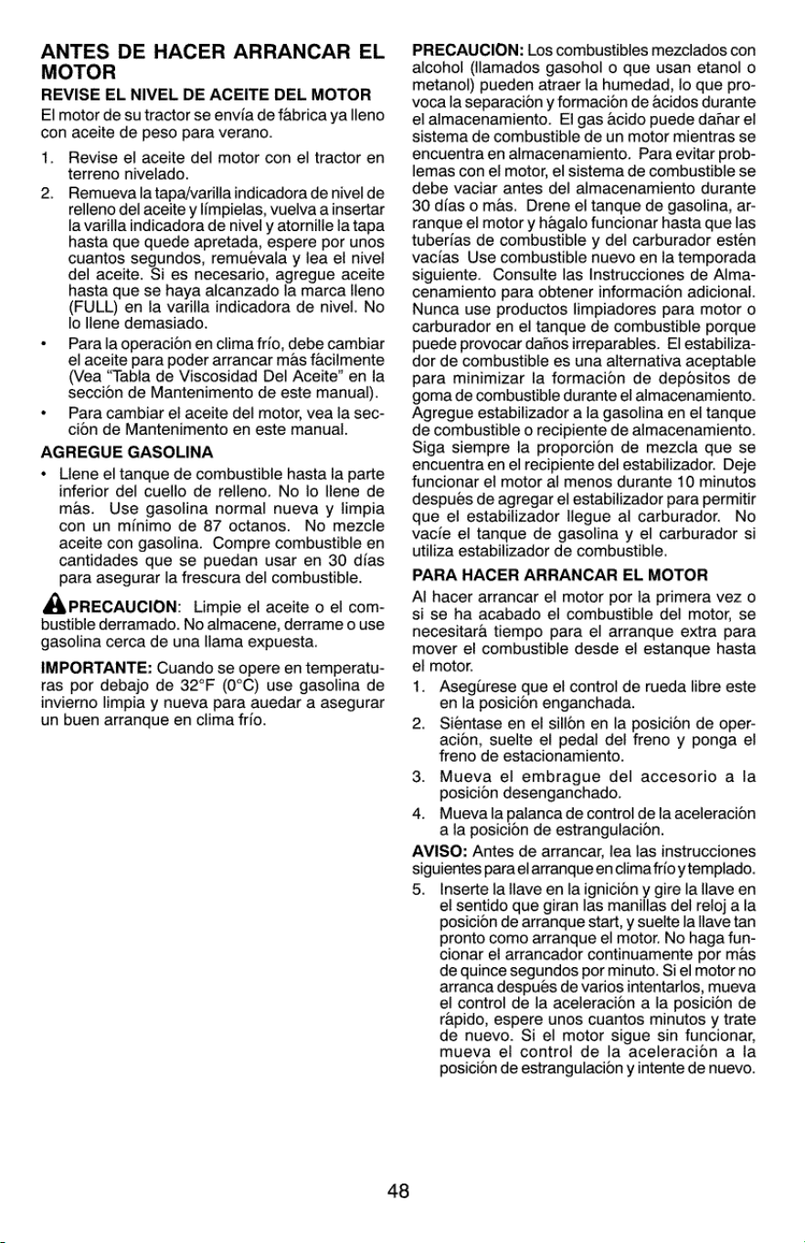
ANTES
DE
HACER
ARRANCAR
EL
MOTOR
REVISE
EL
NIVEL
DE
ACEITE
DEL
MOTOR
El
motor
de
su
tractor
se
envia
de
fabrica
ya
lleno
con
aceite
de
peso
para
verano.
1.
Revise
el
aceite
del
motor
con
el
tractor
en
terreno
nivelado.
Remueva
la
tapa/varilla
indicadora
de
nivel
de
relleno
del
aceite
y
limpielas,
vuelva
a
insertar
la
varilla
indicadora
de
nivel
y
atornille
latapa
hasta
que
quede
apretada,
espere
por
unos
cuantos
segundos,
remuévala
y
jea
el
nivel
del
aceite.
Si
es
necesario,
agregue
aceite
hasta
que
se
haya
alcanzado
la
marca
Ileno
(FULL)
en
Ia
varilla
indicadora
de
nivel.
No
lo
lene
demasiado.
Para
la
operacion
en
clima
frio,
debe
cambiar
el
aceite
para
poder
arrancar
mas
facilmente
(Vea
“Tabla
de
Viscosidad
Del
Aceite”
en
la
seccion
de
Mantenimento
de
este
manual).
Para
cambiar
ei!
aceite
del
motor,
vea
la
sec-
cion
de
Mantenimento
en
este
manual.
AGREGUE
GASOLINA
Llene
el
tanque
de
combustible
hasta
la
parte
inferior
del
cuello
de relleno.
No
jo
llene
de
mas.
Use
gasolina
normal
nueva
y
limpia
con
un
minimo
de
87
octanos.
No
mezcle
aceite
con
gasolina.
Compre
combustible
en
cantidades
que
se
puedan
usar
en
30
dias
para
asegurar
la
frescura
del
combustible.
A\PRECAUCION:
Limpie
el
aceite
o
el
com-
bustible
derramado.
No
almacene,
derrame
o
use
gasolina
cerca
de
una
llama
expuesta.
IMPORTANTE:
Cuando
se
opere
en
temperatu-
tas
por
debajo
de
32°F
(0°C)
use
gasolina
de
invierno
limpia
y
nueva
para
auedar
a
asegurar
un
buen
arranque
en
clima
frio.
2.
48
PRECAUCION:
Los
combustibles
mezclados
con
alcohol
(ilamados
gasohol
0
que
usan
etanol
o
metanol)
pueden
atraer
la
humedad,
lo
que
pro-
voca
la
separacion
y
formacion
de
acidos
durante
el
almacenamiento.
El
gas acido
puede
dahar
el
sistema
de
combustible
de
un
motor
mientras
se
encuentra
en
almacenamiento.
Para
evitar
prob-
lemas
con
el
motor,
el
sisterna
de
combustible
se
debe
vaciar
antes
del
almacenamiento
durante
30
dias
o
mas.
Drene
el
tanque
de
gasolina,
ar-
ranque
el
motor
y
hagalo
funcionar
hasta
que
las
tuberias
de
combustible
y
del
carburador
esten
vacias
Use
combustible
nuevo
en
la
temporada
siguiente.
Consulte
las
Instrucciones
de
Alma-
cenamiento
para
obtener
informacion
adicional.
Nunca
use
productos
limpiadores
para
motor
o
carburador
en
el
tanque
de
combustible
porque
puede
provocar
danos
irreparables.
El
estabiliza-
dor
de
combustible
es
una
alternativa
aceptable
para
minimizar
la
formacion
de
depositos
de
goma
de
combustibie
durante
el
almacenamiento.
Agregue
estabilizador
a
la
gasolina
en
el
tanque
de
combustible
o
recipiente
de
almacenamiento.
Siga
siempre
la
proporcion
de
mezcla
que
se
encuentra
en
el
recipiente
del
estabilizador.
Deje
funcionar
el
motor
al
menos
durante
10
minutos
después
de
agregar
el
estabilizador
para
permitir
que
el
estabilizador
llegue
al
carburador.
No
vacie
el
tanque
de
gasolina
y
el
carburador
si
utiliza
estabilizador
de
combustible.
PARA
HACER
ARRANCAR
EL
MOTOR
Al
hacer arrancar
el
motor
por
la
primera
vez
o
si
se
ha
acabado
el
combustible
de!
motor,
se
necesitara
tiempo
para
el
arranque
extra
para
mover
el
combustible
desde
el
estanque
hasta
el
motor.
1.
Asegurese
que
el
control
de
rueda
libre
este
en
la
posicion
enganchada.
2.
Sientase
en
el
sillon
en
la
posicion
de
oper-
acion,
suelte
el
pedal
del
freno
y
ponga
el
freno
de
estacionamiento.
3.
Mueva
el
embrague
del
accesorio
a
la
posicion
desenganchado.
4.
Muevalapalanca
de
control
de
la
aceleracion
a
la
posicion
de
estrangulacion.
AVISO:
Antes
de
arrancar,
lea
las
instrucciones
siguientes
para
el
arranque
enclima
frio
y
templado.
5.
Inserte
la
lave
en
la
ignicion
y
gire
la
Have
en
el
sentido
que
giran
las
manillas
del
reloj
ala
posicion
de
arranque
start,
y
suelte
la
llave
tan
pronto
como
arranque
el
motor.
No
haga
fun-
cionar
el
arrancador
continuamente
por
mas
de
quince
segundos
por
minuto.
Si
el
motor
no
arranca
después
de
varios
intentarlos,
mueva
el
control
de
la
aceleracion
a
la
posicion
de
rapido,
espere
unos
cuantos minutos
y
trate
de
nuevo.
Si
el
motor
sigue
sin
funcionar,
mueva
el
control
de
la
aceleracion
a
la
posicion
de
estrangulacion
y
intente
de
nuevo.
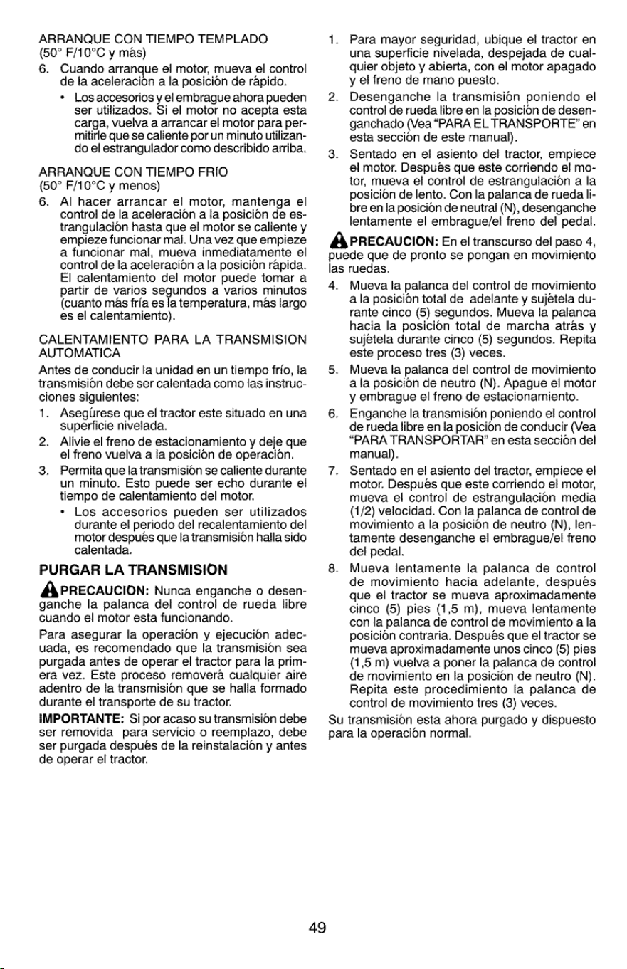
ARRANQUE
CON
TIEMPO
TEMPLADO
(50°
F/10°C
y
mas)
6.
Cuando
arranque
el
motor,
mueva
el
control
de
Ia
aceleracion
a
la
posicion
de
rapido.
*
Los
accesorios
y
el
embrague
ahora
pueden
ser
utilizados.
Si
el
motor
no
acepta
esta
carga,
vuelva
a
arrancar
el
motor
para
per-
mitirle
que
se
caliente
por
un
minuto
utilizan-
do
el
estrangulador
como
describido
arriba.
ARRANQUE
CON
TIEMPO
FRIO
(50°
F/10°C
y
menos)
6.
Al
hacer
arrancar
el
motor,
mantenga
el
control
de
la
aceleracion
a
la
posicion
de
es-
trangulacion
hasta
que
el
motor
se
caliente
y
empieze
funcionar
mai.
Una
vez
que
empieze
a
funcionar
mal,
mueva
inmediatamente
el
control
de
la
aceleracion
a
la
posicion
rapida.
EI
calentamiento
del
motor
puede
tomar
a
partir
de
varios
segundos
a
varios
minutos
(cuanto
mas
fria
es
la
temperatura,
mas
largo
es
el
calentamiento).
CALENTAMIENTO
PARA
LA
TRANSMISION
AUTOMATICA
Antes
de
conducir
la
unidad
en un
tiempo
frio,
la
transmision
debe
ser
calentada
como
las
instruc-
ciones
siguientes:
1.
Asegtrese
que
el
tractor
este
situado
en
una
superficie
nivelada.
2.
Alivie
el
freno
de
estacionamiento
y
deje
que
el
freno
vuelva
a
la
posicion
de
operacion.
3.
Permita
que
la
transmision
se
caliente
durante
un
minuto.
Esto
puede
ser
echo
durante
el
tiempo
de
calentamiento
del
motor.
«
Los
accesorios
pueden
ser
utilizados
durante
ei
periodo
del
recalentamiento
del
motor
después
que
la
transmision
halla
sido
calentada.
PURGAR
LA
TRANSMISION
A\PRECAUCION:
Nunca
enganche
o
desen-
ganche
la
palanca
del
control
de
rueda
libre
cuando
el
motor
esta
funcionando.
Para
asegurar
la
operacion
y
ejecucion
adec-
uada,
es
recomendado
que
la
transmision
sea
purgada
antes
de
operar
el
tractor
para
la
prim-
era
vez.
Este
proceso
removera
cualquier
aire
adentro
de
la
transmision
que
se
halla
formado
durante
el
transporte
de
su
tractor.
IMPORTANTE:
Si
por
acaso
su
transmision
debe
ser
removida
para
servicio
o
reemplazo,
debe
ser
purgada
después
de
la
reinstalacion
y
antes
de
operar
el
tractor.
49
Para
mayor
seguridad,
ubique
el
tractor
en
una
superficie
nivelada,
despejada
de
cual-
quier
objeto
y
abierta,
con
el
motor
apagado
y
el
freno
de
mano
puesio.
2.
Desenganche
la
transmision
poniendo
el
control
de
rueda
libre
en
la
posicion
de
desen-
ganchado
(Vea
“PARA
EL
TRANSPORTE”
en
esta
seccion
de
este
manual).
3.
Sentado
en
el
asiento
del
tractor,
empiece
el
motor.
Después
que
este
corriendo
el
mo-
tor,
mueva
el
control
de
estrangulacion
a
la
posicion
de
lento.
Con
la
palanca
de
rueda
li-
bre en
la
posicion
de
neutral
(N),
desenganche
lentamente
el
embrague/el
freno
del
pedal.
A\PRECAUCION:
En
el
transcurso
del
paso
4,
puede
que
de
pronto
se
pongan
en
movimiento
las
ruedas.
4.
Mueva
la
palanca
del
control
de
movimiento
ala
posicion
total
de
adelante
y
sujetela
du-
rante
cinco
(5)
segundos.
Mueva
la
palanca
hacia
la
posicion
total
de
marcha
atras
y
sujétela
durante
cinco
(5)
segundos.
Repita
este
proceso
tres
(3)
veces.
Mueva
la
palanca
del
control
de
movimiento
ala
posicion
de
neutro
(N).
Apague
el
motor
y
embrague
el
freno
de
estacionamiento.
Enganche
la
transmision
poniendo
el
control
de
rueda
libre
en
la
posicion
de
conducir
(Vea
“PARA
TRANSPORTAR’
en
esta
seccion
del
manual).
Sentado
en
el
asiento
del
tractor,
empiece
el
motor.
Después
que
este
corriendo
el
motor,
mueva
el
control
de
estrangulacion
media
(1/2)
velocidad.
Con
la
palanca
de
control
de
movimiento
a
la
posicion
de
neutro
(N),
len-
tamente
desenganche
el
embraque/el
freno
del
pedal.
Mueva
lentamente
la
palanca
de
control
de
movimiento
hacia
adelante,
despues
que
el
tractor
se
mueva
aproximadamente
cinco
(5)
pies
(1,5
m),
mueva
lentamente
con
la
palanca
de
control
de
movimiento
a
la
posicion
contraria.
Después
que
el
tractor
se
mueva
aproximadamente
unos
cinco
(5)
pies
(1,5
m)
vuelva
a
poner
la
palanca
de
control
de
movimiento
en
la
posicion
de
neutro
(N).
Repita
este
procedimiento
la
palanca
de
control
de
movimiento
tres
(3)
veces.
Su
transmision
esta
ahora
purgado
y
dispuesto
para
la
operacion
normal.
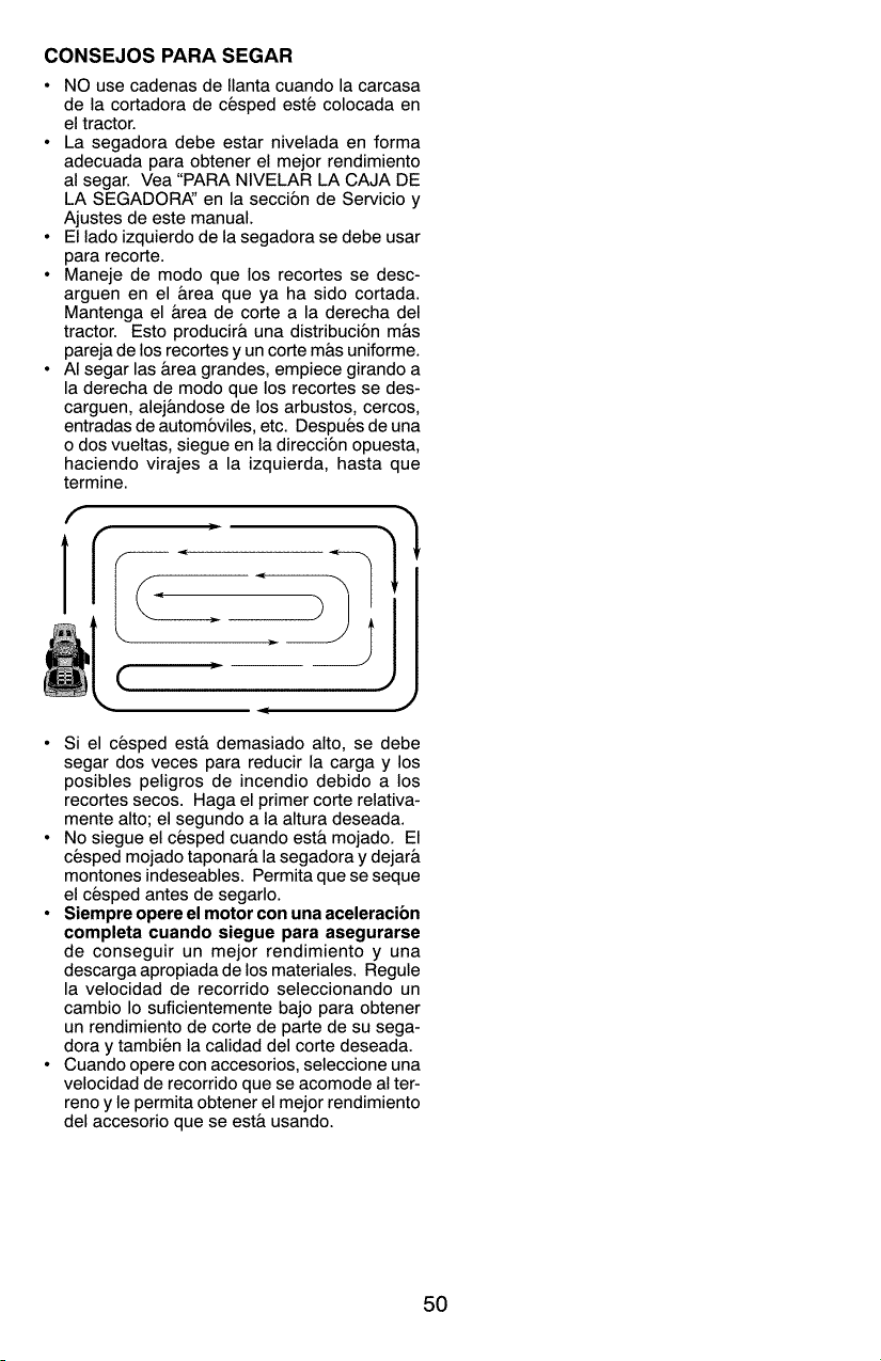
CONSEJOS
PARA
SEGAR
.
NO
use
cadenas
de
llanta
cuando
la
carcasa
de
la
cortadora
de
cesped
este
colocada
en
el
tractor.
La
segadora
debe
estar
nivelada
en
forma
adecuada
para
obtener
el
mejor
rendimiento
al
segar.
Vea
“PARA
NIVELAR
LA
CAJA
DE
LA
SEGADORA’
en
la
seccion
de
Servicio
y
Ajustes
de
este
manual.
EI
lado
izquierdo
de
la
segadora
se
debe
usar
para
recorte.
Maneje
de
modo
que
los
recortes
se
desc-
arguen
en
el
area
que
ya ha
sido
cortada.
Mantenga
el
area
de
corte
a
la
derecha
del
tractor.
Esto
producira
una
distribucion
mas
pareja
de
los
recortes
y
un
corte
mas
uniforme.
Al
segar
las
area
grandes,
empiece
girando
a
la
derecha
de
modo
que
los
recortes
se
des-
carguen,
alejandose
de
los
arbustos,
cercos,
entradas
de
automoviles,
etc.
Después
de
una
o
dos
vueltas,
siegue
en
la
direccion
opuesta,
haciendo
virajes
a
la
izquierda,
hasta
que
SSE
S55)
Si
el
cesped
esta
demasiado
alto,
se
debe
segar
dos
veces
para
reducir
la
carga
y
los
posibles
peligros
de
incendio
debido
a
los
recortes
secos.
Haga
el
primer
corte
relativa-
mente
alto;
el
segundo
a
la
altura
deseada.
No
siegue
e/
cesped
cuando
esta
mojado.
El
césped
mojado
taponara
la
segadora
y
dejara
montones
indeseables.
Permita
que
se
seque
el
cesped
antes
de
segarlo.
Siempre
opere
el
motor
con
una
aceleracion
completa
cuando
siegue
para
asegurarse
de
conseguir
un
mejor
rendimiento
y
una
descarga
apropiada
de
los
materiales.
Reguie
la
velocidad
de
recorrido
seleccionando
un
cambio
lo
suficientemente
bajo
para
obtener
un
rendimiento
de
corte de
parte
de
su
sega-
dora
y
también
la
calidad
del
corte
deseada.
Cuando
opere
con
accesorios,
seleccione
una
velocidad
de
recorrido
que
se
acomode
al
ter-
reno
y le
permita
obtener
el
mejor
rendimiento
del
accesorio
que
se
esta
usando.
r
50
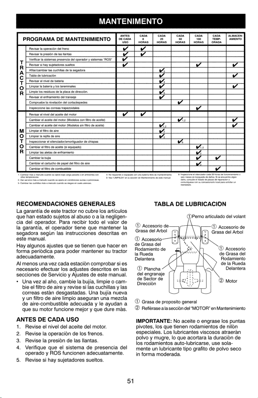
MANTENIMENT
Revisar
la
del
freno
de
las
llantas
del
Revisar
la
Verificar
la
sistemas sistemas
"ROS”
Revisar
si
sueltos
Afilar/cambiar
las
cuchillas
de
ta
Tabla
de
fubricacion
Revisar
ef
nivel
de
bateria
la
bateria
y
los
tereminales
los
residuos
de
la
de
direccién.
BOAOPAAs
Revisar
el
enfriamiento
del
la
nivelacion
det
las
correas
Revisar
ei
nivel
del
aceite
del
motor
Cambiar
el
aceite
def
motor
con
filtro
de
Cambiar
el
aceite
del
motor
sin
filtro
de
el
filtro
de
aire
ta
de
aire
et
Cambiar
el
filtro
de
aceite
las
aletas
de
enfriamiento
Cambiar
la
Cambiar
el
cartucho
de
del
filtro
de
aire
Cambiar
el
filtro
de
combustible
+-
Cambiar
mds
a
menudo
cuando
se
opere
bajo
carga
pesada
o
en
ambientes
con
alias
temperaturas
2 Dar
servicio
mas
a
menudo
cuando
se
opere
en
condiciones
sucias
0
polvorosas.
3
Cambiar
las
cuchiias
mas
a
menudo
cuando
se
siegue
en
eusto
arenoso,
RECOMENDACIONES
GENERALES
La
garantia
de
este
tractor
no
cubre
los
articulos
que
han
estado
sujetos
al
abuso
0
a
la
negligen-
cia del
operador.
Para
recibir
todo
el
valor
de
la
garantia,
el
operador
tiene
que
mantener
la
segadora
segtn
las
instrucciones
descritas
en
este
manual.
Hay algunos
ajustes
que
se
tienen
que hacer
en
forma
periddica
para
poder
mantener
su
tractor
adecuadamente.
Al
menos
una
vez
cada
estacion
comprobar
si
es
necesario
efectuar
los
adjustes
descritos
en
las
secciones
de
Servicio
y
Ajustes
de
este
manual.
Una
vez
al
ano,
cambie
la
bujfa,
limpie
o
cam-
bie
el
filtro
de
aire
y
revise
si
las
cuchillas
y
las
correas
estan
desgastadas.
Una
bujia
nueva
y
un
filtro
de
aire
limpio
aseguran
una
mezcla
de
aire-combustible
adecuada
y
le
ayudan
a
que
su
motor
funcione
mejor
y
que
dure
mas.
ANTES
DE
CADA
USO
e
1.
Revise
el
nivel
del
aceite
del
motor.
2.
Revise
la
operacion
de
los
frenos.
3.
Revise
la
presion
de
las
llantas.
4.
Verifique
que
el
sistema
de
presencia
del
operado
y
ROS
funcionen
adecuatamente.
5.
Revise
si
hay
sujetadores
sueltos.
S
DA
PROGRAMA
DE
MANTENIMIENTO
|
2
cx
4-
No
requerico
si
equipado
con
una
bateria
libre
de
mantenimiante.
5-
Vea
“LIMPIEZA"
on
la
seccién
de
Mantenimento
de este
manuat
51
CADA CADA CADA CADA
100
HORAS
CADA
TEMP-
ORADA
ALMACEN-
38
25
50
AMIENTO
HORAS
HORAS HORAS
6
Inspecciane
et
silenciador
cada
50
horas
de
funcionamiento
0
seis
meses
en
busqueda
de
darios,
Si
se
encuentra
algun
dao,
consuite
el
listado de
piezas
de
reparacion
somuniquese
con
su
concesionario
local
para
solicitar
un
reempiazo.
TABLA
DE
LUBRICACION
@Perno
articulado
del
volant
@®
Accesorio
de
Grasa
del
Arbol
@®
Accesorio
de
Grasa
del
Arbol
@®
Accesorio
de
Grasa
del
Rodamiento
de
®
Accesorio
laRueda
ss
|}
ee
de
Grasa
del
Delantera
Rodamiento
de
la
Rueda
®
Plancha
Delantera
del
engranaje
de
Sector
de
®
Motor
Direccion
@®
Grasa
de
proposito
general
@
Refiérase
ala
seccion
del
“MOTOR”
en
Mantenimiento
IMPORTANTE:
No
aceite
o
engrase
los
puntas
pivotes,
los
que
tienen
rodamientos
de
nilon
especiales.
Los
lubricantes
viscosos
atraeran
polvo
y
mugre,
lo
que
acortara
la
duracion
de
los
rodamientos
auto-lubricarse,
use
sola-
mente
un
lubricante
tipo
grafito
de
polvo
seco
in
forma
moderada.
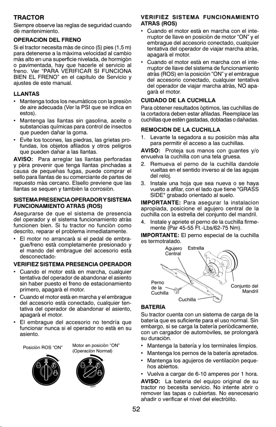
TRACTOR
Siempre
observe
las
reglas
de
seguridad
cuando
de
mantenimiento.
OPERACION
DEL
FRENO
Si
el
tractor
necesita
mas
de
cinco
(5)
pies
(1,5
m)
para
detenerse
a
la
maxima
velocidad
al
cambio
mas
alto
en
una
superficie
nivelada,
de
hormigon
0
pavimentada,
hay
que
hacerle
el
servicio
al
freno.
Ver
“PARA
VERIFICAR
SI
FUNCIONA
BIEN
EL
FRENO”
en
el
capitulo
de
Servicio
y
ajustes
de
este
manual.
LLANTAS
Mantenga
todos
los
neumaticos
con
la
presion
de
aire
adecuada
(Ver
la
PSI
que
se
indica
en
estos).
Mantenga
las
llantas
sin
gasolina,
aceite
o
substancias
quimicas
para
control
de
insectos
que
pueden
danar
la
goma.
Evite
los
tocones,
las
piedras,
las
grietas
pro-
fundas,
los
objetos
afilados
y
otros
peligros
que
pueden
danhar
a
las
llantas.
AVISO:
Para
arreglar
las
llantas
perforadas
y
pera
prevenir
que
tenga
llantas
pinchadas
a
causa
de
pequenas
fugas,
puede
comprar
el
sello
para
llantas
de
su
comerciante
de
partes
de
repuesto
mas
cercano.
Elsello
previene
que
las
llantas
se
sequen
y
también
fa
corrosion.
SISTEMA
PRESENCIA
OPERADORY
SISTEMA
FUNCIONAMIENTO
ATRAS
(ROS)
Asegurarse
de
que
el
sistema
de
presencia
de!
operador
y
el
sistema
funcionamiento
atras
funcionen
bien.
Si tu
tractor
no
funcion
como
descrito,
reparar
el
problema
inmediatamente.
*
El
motor
no
arrancara
si
el
pedal
de
embra-
gue/freno
esta
completamente
presionado
y
el
mando
del
embrague
del
accesorio
esta
desconectado:
VERIFIEZ
SISTEMA
PRESENCIA
OPERADOR
Cuando
el
motor
esta
en
marcha,
cualquier
tentativa
del
operador
de
abandonar
el
asiento
sin
haber
puesto
el
freno
de
estacionamiento
primero,
apagara
el
motor.
Cuando
el
motor
esta
en
marcha
y
el
embrague
del
accesorio
esta
conectado,
cualquier
ten-
tativa
del
operador
de
abandonar
el
asiento,
apagara
el
motor.
El
embrague
del
accesorio
no
tendria
que
funcionar
nunca
si
el
operador
no
esta
en
su
asiento.
°
Motor
en
posicién
“ON”
Posicion
ROS
“ON”
Heron
j
(Operacion
Normal)
52
VERIFIEZ
SISTEMA
FUNCIONAMIENTO
ATRAS
(ROS)
Cuando
el
motor
esta
en
marcha
con
el
inte-
rruptor
de
llave
en
posicion
de
motor
“ON’
y
el
embrague
del
accesorio
conectado,
cualquier
tentativa
del
operador
de
viajar
marcha
atras,
apagara
el
motor.
Cuando
el
motor
esta
en
marcha
con
el
inte-
rruptor
de
llave
del
sistema
de
funcionamiento
atras
(ROS)
en
la
posicion
“ON”
y
el
embrague
del
accesorio
conectado,
cualquier
tentativa
del
operador
de
viajar
marcha
atras,
NO
apa-
gara
el
motor.
CUIDADO
DE LA
CUCHILLA
Para
obtener
resultados
optimos,
las
cuchillas
de
la
cortadora
deben
estar
afiladas.
Reemplace
las
cuchillas
que
estén
gastadas,
dobladas
o
dahadas.
REMOCION
DE LA
CUCHILLA
1.
Levante
la
segadora
a
su
posicion
mas
alta
para
permitir
el
acceso
a
las
cuchillas.
AVISO:
Proteja
sus
manos
con
guantes
y/o
envuelva
la
cuchilla
con
una
tela
gruesa.
2.
Remueva
el
perno
de
la
cuchilla
dandole
vueltas
en
el
sentido inverso
al
de
las
agujas
del
reloj.
3.
Instale
una
hoja
que
sea
nueva
o
se
haya
vuelto
a
afilar,
con
el
lado
que
tiene
"GRASS
SIDE"
grabado
orientado
al
suelo.
IMPORTANTE:
Para
asegurar
la
instalacion
apropiada,
posicione
el
agujero
central
de
la
cuchilla
con
la
estrella
del
conjunto
del
mandril.
4.
Instale
y
apriete
el
perno
de
la
cuchilla
firme-
mente
(Par
45-55
Ft.-Lbs/62-75
Nm).
IMPORTANTE:
El
perno
especial
de
la
cuchilla
es
termotratado.
Agujero
Central
Estrella
reine
a
Conjunto
del
Cuchilla
a
Manaril
Cuchilla
——~
CJ
BATERIA
Su
tractor
cuenta
con
un
sistema
de
carga
de
la
bateria
que
es
suficiente
para
el
uso
normal.
Sin
embargo,
si
se
carga
la
bateria
periodicamente,
con
un
cargador
de
automoviles,
se
prolongara
su
duracion.
*
Mantenga
la
bateria
y
los
terminales
limpios.
+
Mantenga
los
pernos
de
Ia
bateria
apretados.
+
Mantenga
los
agujeros
de
ventilacion
peque-
hos
abiertos.
«
Vuelva
a
cargar
de
6-10
amperes
por
1
hora.
AVISO:
La
bateria
del
equipo
original
de
su
tractor
no
becesita
servicio.
No
intente
abrir
o
remover
las
tapas
o
cubiertas.
No
esnecesario
anadir
o
verificar
el
nivel
del
electrolito.
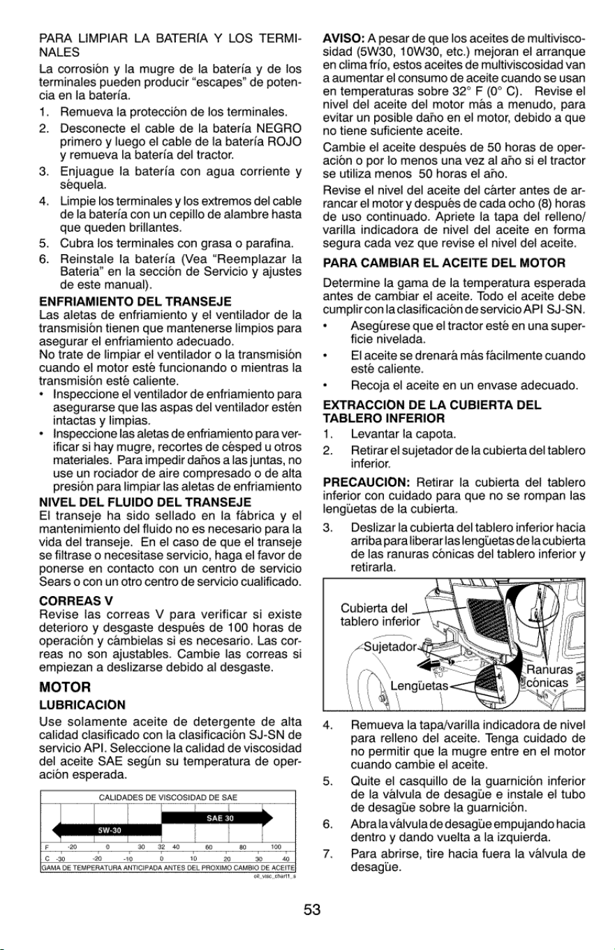
PARA
LIMPIAR
LA
BATERIA
Y
LOS
TERMI-
NALES
La
corrosion
y
la
mugre
de
la
bateria
y
de
los
terminales
pueden
producir
“escapes”
de
poten-
cia
en
la
bateria.
1.
Remueva
la
proteccion
de
los
terminales.
2.
Desconecte
el
cable
de
la
bateria
NEGRO
primero
y
luego
el
cable
de
la
bateria
ROJO
y
remueva
la
bateria
del
tractor.
3.
Enjuague
la
bateria con
agua
corriente
y
sequela,
4.
Limpie
los
terminales
y
los
extremos
del
cable
de
la
baterfa
con
un
cepillo
de
alambre
hasta
que
queden
brillantes.
5.
Cubra
los
terminales
con
grasa
o
parafina.
6.
Reinstale
la
bateria
(Vea
“Reemplazar
ia
Bateria”
en
la
seccion
de
Servicio
y
ajustes
de
este
manual).
ENFRIAMIENTO
DEL
TRANSEJE
Las
aletas
de
enfriamiento
y
el
ventilador
de
la
transmision
tienen
que
mantenerse
limpios
para
asegurar
el
enfriamiento
adecuado.
No
trate
de
limpiar
el
ventilador
o
la
transmision
cuando
el
motor
esté
funcionando
o
mientras
la
transmision
este
caliente.
Inspeccione
el
ventilador
de
enfriamiento
para
asegurarse
que
las
aspas
del
ventilador
estén
intactas
y
limpias.
inspeccione
las
aletas
de
enfriamiento
para
ver-
ificar
si
hay
mugre,
recortes
de
cesped
u
otros
materiales.
Para
impedir
danos
a
las
juntas,
no
use
un
rociador
de
aire
compresado
o
de
alta
presion
para
limpiar
las
aletas
de
enfriamiento
NIVEL
DEL
FLUIDO
DEL
TRANSEJE
El
transeje
ha
sido
sellado
en
la
fabrica
y
el
mantenimiento
del
fluido
no
es
necesario
para
la
vida
del
transeje.
En
el
caso
de
que
el
transeje
se
filtrase
o
necesitase
servicio,
haga
el
favor
de
ponerse
en
contacto
con
un
centro
de
servicio
Sears
0
con
un
otro
centro
de
servicio
cualificado.
CORREAS
V
Revise
las
correas
V
para
verificar
si
existe
deterioro
y
desgaste
después
de
100
horas
de
operacion
y
cambielas
si
es
necesario.
Las
cor-
reas
no
son
ajustables.
Cambie
las
correas
si
empiezan
a
deslizarse
debido
al
desgaste.
MOTOR
LUBRICACION
Use
solamente
aceite
de
detergente
de
alta
calidad
clasificado con
la
clasificacion
SJ-SN
de
servicio
API.
Seleccione
la
calidad
de
viscosidad
del
aceite
SAE
segiin
su
temperatura
de
oper-
acion
esperada.
e
CALIDADES
DE
VISCOSIDAD
DE
SAE
53
AVISO:
A
pesar
de
que
los
aceites
de
multivisco-
sidad
(6W30,
10WS30,
etc.)
mejoran
el
arranque
en
clima
frio,
estos
aceites
de
multiviscosidad
van
a
aumentar
el
consumo
de
aceite
cuando
se
usan
en
temperaturas
sobre
32°
F
(0°
C).
Revise
el
nivel
del
aceite
del
motor
mas
a
menudo,
para
evitar
un
posible
dano
en
el
motor,
debido
a
que
no
tiene
suficiente
aceite.
Cambie
el
aceite
despues
de 50
horas
de
oper-
acion
o
por
lo
menos
una
vez
al
afho
si
el
tractor
se
utiliza
menos
50
horas
el
ano.
Revise
el
nivel
del
aceite
del
carter
antes
de
ar-
rancar
el
motor
y
después
de
cada
ocho
(8)
horas
de
uso
continuado.
Apriete
la
tapa
del
relleno/
varilla
indicadora
de
nivel
del
aceite
en
forma
segura
cada
vez
que
revise
el
nivel
del
aceite.
PARA
CAMBIAR
EL
ACEITE
DEL
MOTOR
Determine
la
gama
de
la
temperatura
esperada
antes
de
cambiar
el
aceite.
Todo
el
aceite
debe
cumplir
con
la
clasificacion
de
servicio
API
SJ-SN.
Asegirese
que
el
tractor
esté
en
una
super-
ficie
nivelada.
El
aceite
se
drenara
mas
facilmente
cuando
esté caliente.
Recoja
el
aceite
en
un
envase
adecuado.
EXTRACCION
DE LA
CUBIERTA
DEL
TABLERO
INFERIOR
1.
Levantar
la
capota.
2.
Retirar
el
sujetador
de
la
cubierta
del
tablero
inferior.
PRECAUCION:
Retirar
la
cubierta
del
tablero
inferior
con
cuidado
para
que
no
se
rompan
las
lengiietas
de
la
cubierta.
3.
Destlizar
la
cubierta
del
tablero
inferior
hacia
arriba
para
liberar
las
lengiietas
de
la
cubierta
de
las
ranuras conicas
del
tabiero
inferior
y
retirarla.
ae
Remueva
la
tapa/varilla
indicadora
de
nivel
para
relleno
del
aceite.
Tenga
cuidado
de
no
permitir
que
la
mugre
entre
en
el
motor
cuando
cambie
el
aceite.
Quite
el
casquillo
de
la
guarnicion
inferior
de
la
valvula
de
desagtie
e
instale
el
tubo
de
desagte
sobre
la
guarnicion.
Aobrala
valvula
de
desague
empujando
hacia
dentro
y
dando
vuelta
a
la
izquierda.
Para
abrirse,
tire
hacia
fuera
la
valvula
de
desagile.
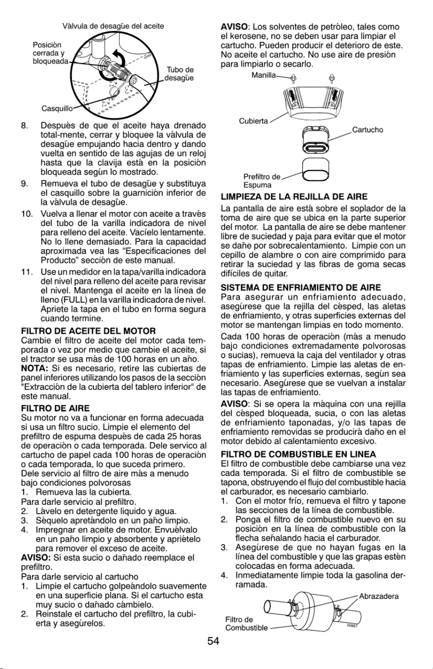
Valvula
de
desaglie
del
aceite
Posicion
cerrada
y
8.
Despues
de
que
el
aceite
haya
drenado
total-mente,
cerrar
y
bloquee
la
valvula
de
desagtie
empujando
hacia
dentro
y
dando
vuelta
en
sentido
de
las
agujas
de
un
reloj
hasta
que
fa
clavija
esta
en
la
posicion
bloqueada
segin
lo
mostrado.
9.
Remueva
el
tubo
de
desagitle
y
substituya
el
casquillo
sobre
la
guarnicion
inferior
de
la
valvula
de
desagtie.
10.
Vuelva
a
llenar
el
motor
con
aceite
a
traves
del
tubo
de
la
varilla
indicadora
de
nivel
para
relleno
del
aceite.
Vacielo
lentamente.
No
lo
llene
demasiado.
Para
la
capacidad
aproximada
vea
las
“Especificaciones
del
Producto”
seccion
de
este
manual.
11.
Useun
medidor
en
la
tapa/varilla
indicadora
del
nivel
para
relleno
del
aceite
para
revisar
el
nivel.
Mantenga
el
aceite
en
la
linea de
lleno
(FULL)
en
la
varilla
indicadora
de
nivel.
Apriete
la
tapa
en
el
tubo
en
forma
segura
cuando
termine.
FILTRO
DE
ACEITE
DEL
MOTOR
Cambie
el
filtro
de
aceite
del
motor
cada
tem-
porada
o
vez
por
medio
que
cambie
el
aceite,
si
el
tractor
se
usa
mas
de
100
horas
en
un
ano.
NOTA:
Si
es
necesario,
retire
las
cubiertas
de
panel
inferiores
utilizando
los
pasos
de
la
seccion
“Extraccion
de
la
cubierta
del
tablero
inferior"
de
este
manual.
FILTRO
DE
AIRE
Su
motor
no
va
a
funcionar
en
forma
adecuada
si
usa
un
filtro
sucio.
Limpie
el
elemento
del
prefiltro
de
espuma
despues
de
cada
25
horas
de
operacion
o
cada
temporada.
Dele
servico
al
cartucho
de
papel
cada
100
horas
de
operacion
o
cada
temporada,
lo
que
suceda
primero.
Dele
servicio
al
filtro
de
aire
mas
a
menudo
bajo
condiciones
polvorosas
1.
Remueva
las
la
cubierta.
Para
darle
servicio
al
prefiltro.
2.
Lavelo
en
detergente
liquido
y
agua.
3.
Séquelo
apretandolo
en un
paho
limpio.
4.
Impregnar
en
aceite
de
motor.
Envuélvalo
en un
paho
limpio
y
absorbente
y
aprietelo
para
remover
el
exceso
de
aceite.
AVISO:
Si
esta
sucio
o
danado
reempiace
el
prefiltro.
Para
darle
servicio
al
cartucho
1.
Limpie
el
cartucho
golpeandolo
suavemente
en
una
superficie
plana.
Si
el
cartucho
esta
muy
sucio
o
dahado
cambielo.
2.
Reinstale
el
cartucho
del
prefiltro,
la
cubi-
erta
y
asegtrelos.
AVISO:
Los
solventes
de
petroleo,
tales
como
el
kerosene,
no
se
deben
usar
para
limpiar
el
cartucho.
Pueden
producir
el
deterioro
de este.
No
aceite
el
cartucho.
No
use
aire
de
presion
para
limpiarlo
o
secarlo.
Manilla——_¢,
@
-
Cartucho
Prefiltro
nO
Espuma
LIMPIEZA
DE LA
REJILLA
DE
AIRE
La
pantalla
de
aire
esta
sobre
el
soplador
de
la
toma
de
aire
que
se
ubica
en
la
parte
superior
del
motor.
La
pantalla
de
aire
se
debe
mantener
libre
de
suciedad
y
paja
para
evitar
que
el
motor
se
dane
por
sobrecalentamiento.
Limpie
con
un
cepillo
de
alambre
o
con
aire
comprimido
para
retirar
la
suciedad
y
las
fibras
de
goma
secas
dificiles
de
quitar.
SISTEMA
DE
ENFRIAMIENTO
DE
AIRE
Para
asegurar
un
enfriamiento
adecuado,
asegurese
que
la
rejilla
del
cesped,
las
aletas
de
enfriamiento,
y
otras
superficies
externas
del
motor
se
mantengan
limpias
en
todo
momento.
Cada
100
horas
de
operacion
(mas
a
menudo
bajo
condiciones
extremadamente
polvorosas
0
sucias),
remueva
la
caja
del
ventilador
y
otras
tapas
de
enfriamiento. Limpie
las
aletas
de
en-
friamiento
y
las
superficies
externas,
segun
sea
necesario.
Aseglirese
que
se
vuelvan
a
instalar
las
tapas
de
enfriamiento.
AVISO:
Si
se
opera
la
maquina
con
una
refilla
del
cesped
bloqueada,
sucia,
o
con
las
aletas
de
enfriamiento
taponadas,
y/o
las
tapas
de
enfriamiento
removidas
se
producira
daho
en
el
motor
debido
al
calentamiento
excesivo.
FILTRO
DE
COMBUSTIBLE
EN
LINEA
EI
filtro
de
combustible
debe
cambiarse
una
vez
cada
temporada.
Si
ei
filtro
de
combustible
se
tapona,
obstruyendo
el
flujo
del
combustible
hacia
el
carburador,
es
necesario
cambiarlo.
1.
Con
el
motor
frio,
remueva
el
filtro
y
tapone
las
secciones
de
la
linea de
combustible.
2.
Ponga
el
filtro
de
combustible
nuevo
en
su
posicion
en
la
linea de
combustible
con
fa
flecha
senhalando
hacia
el
carburador.
Asegurese
de
que
no
hayan
fugas
en
la
linea
del
combustible
y
que
las
grapas
esten
colocadas
en
forma
adecuada.
4.
Inmediatamente
limpie
toda
la
gasolina
der-
ramada.
Abrazadera
Filtro
de
Combustible
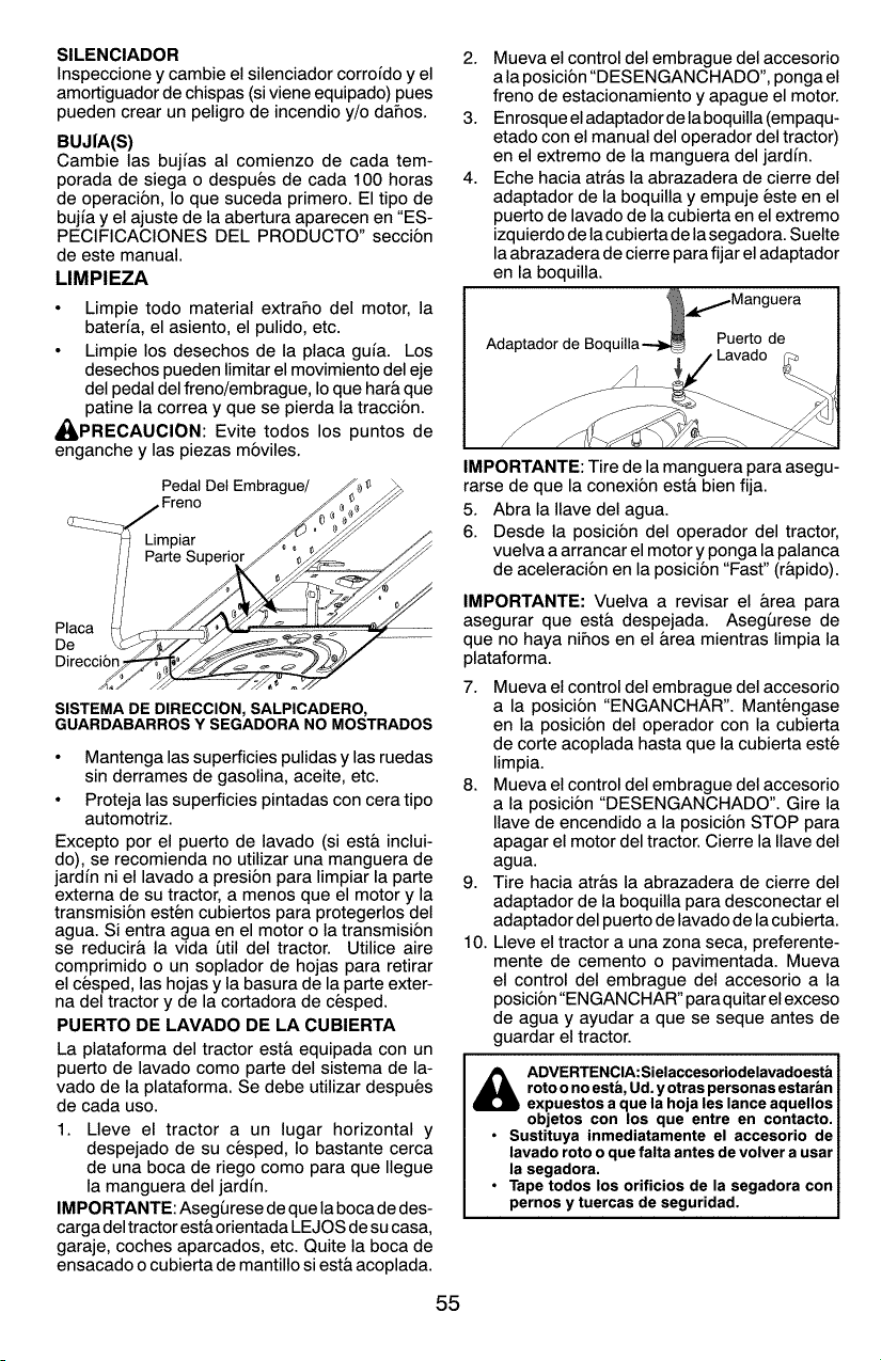
SILENCIADOR
Inspeccione
y
cambie
el
silenciador
corrojdo
y
el
amortiguador
de
chispas
(si
viene
equipado)
pues
pueden
crear
un
peligro
de
incendio
y/o
dahos.
BUJIA(S)
Cambie
las
bujfas
al
comienzo
de
cada
tem-
porada
de
siega
o
después
de
cada
100
horas
de
operacion,
lo
que
suceda
primero.
El
tipo
de
bujfa
y
el
ajuste
de
la
abertura
aparecen
en
“ES-
PECIFICACIONES
DEL
PRODUCTO”
seccion
de
este
manual.
LIMPIEZA
Limpie
todo material
extraho
del
motor,
la
bateria,
el
asiento,
el
pulido,
etc.
Limpie
los
desechos
de
la
placa
guia.
Los
desechos
pueden
limitar
el
movimiento
del
eje
del
pedal
del
freno/embrague,
lo
que
hara
que
patine
la
correa
y
que
se
pierda
la
traccion.
APRECAUCION:
Evite
todos
los
puntos
de
enganche
y
las
piezas
moviles.
Pedal
Dei
Embrague/
Freno
ep
|
Parte
Superior
x
Aa
a®
SISTEMA
DE
DIRECCION,
SALPICADERO,
GUARDABARROS
Y
SEGADORA
NO
MOSTRADOS
Mantenga
las
superficies
pulidas
y
las
ruedas
sin
derrames
de
gasolina,
aceite,
etc.
Proteja
las
superficies
pintadas
con
cera
tipo
automotriz.
Excepto
por
el
puerto
de
lavado
(si
esta
inclui-
do),
se
recomienda
no
utilizar
una
manguera
de
jardin
ni
el
lavado
a
presion
para
limpiar
la
parte
externa
de
su
tractor,
a
menos
que
el
motor
y la
transmision
estén
cubiertos
para
protegerlos
del
agua.
Si
entra
agua
en
el
motor
o
la
transmision
se
reducira
la
vida
Util
del
tractor.
Utilice
aire
comprimido
o
un
soplador
de
hojas
para
retirar
el
cesped,
las
hojas
y
la
basura
de
la
parte
exter-
na
del
tractor
y
de
la
cortadora
de
cesped.
PUERTO
DE
LAVADO
DE LA
CUBIERTA
La
plataforma
del
tractor
esta
equipada
con
un
puerto
de
lavado
como
parte
del
sistema
de
la-
vado
de
la
plataforma.
Se
debe
utilizar
despues
de
cada
uso.
1.
Lleve
el
tractor
a
un
lugar
horizontal
y
despejado
de
su
cesped,
lo
bastante
cerca
de
una
boca
de
riego
como
para
que
llegue
la
manguera
del
jardin.
IMPORTANTE:
Asegirese
de
quela boca
de
des-
carga
deltractor
esta
orientada
LEJOS
de
sucasa,
garaje,
coches
aparcados,
etc.
Quite
la
boca
de
ensacado
o
cubierta
de
mantillo
si
esta
acoplada.
*
55
Mueva
el
contro!
del
embrague
del
accesorio
ala
posicion
“DESENGANCHADO”,
pongael
freno
de
estacionamiento
y
apague
el
motor.
Enrosque
el
adaptador
dela
boquilla
(empaqu-
etado
con
el
manual
del
operador
del
tractor)
en
el
extremo
de
la
manguera
del
jardin.
Eche
hacia
atras
la
abrazadera
de
cierre
del
adaptador
de
la
boquilla
y
empuje
este
en
el
puerto
de
lavado
de
la
cubierta
en
el
extremo
izquierdo
dela
cubierta
dela
segadora.
Suelte
la
abrazadera
de
cierre
para
fijar
el
adaptador
en
la
boquilla.
ee
Manguera
IMPORTANTE:
Tire
de
la
manguera
para
asegu-
rarse
de
que
la
conexion
esta
bien
fija.
5.
Abra
la
llave
del
agua.
6.
Desde
la
posicion
del
operador
del
tractor,
vuelva
a
arrancar
el
motor
y
ponga
la
palanca
de
aceleracion
en
la
posicion
“Fast”
(rapido).
IMPORTANTE:
Vuelva
a
revisar
el
area para
asegurar
que
esta
despejada.
Aseglrese
de
que
no
haya
nihos
en
el
area
mientras
limpia
la
plataforma.
7.
Mueva
el
control
del
embrague
del
accesorio
a
la
posicion
“ENGANCHAR’.
Mantengase
en
la
posicion
del
operador
con
la
cubierta
de
corte
acoplada
hasta
que
la
cubierta
esté
limpia.
Mueva
el
control
del
embrague
del
accesorio
a
la
posicion
“DESENGANCHADO”.
Gire
la
llave
de
encendido
a
la
posicion
STOP
para
apagar
el
motor
del
tractor.
Cierre
la
llave
del
agua.
Tire
hacia
atras
la
abrazadera
de
cierre
del
adaptador
de
la
boquilla
para
desconectar
el
adaptador
del
puerto
de
lavado
dela
cubierta.
Lieve
el
tractor
a
una
zona
seca,
preferente-
mente
de
cemento
o
pavimentada.
Mueva
el
control
del
embrague
del
accesorio
a
la
posicion
“ENGANCHAR’
para
quitar
el
exceso
de
agua
y
ayudar
a
que
se
seque
antes
de
guardar
el
tractor.
A
expuestos
a
que
la
hoja
les
lance
aquellos
objetos
con
los
que
entre
en
contacto.
*
Sustituya
inmediatamente
el
accesorio
de
lavado
roto
o
que
falta
antes
de
volver
a
usar
la
segadora.
*
Tape
todos
Ios
orificios
de
la
segadora
con
pernos
y
tuercas
de
seguridad.
9.
10.
ADVERTENCIA:Sielaccesoriodelavadoesta
roto
onoesta,
Ud.
y
otras
personas
estaran
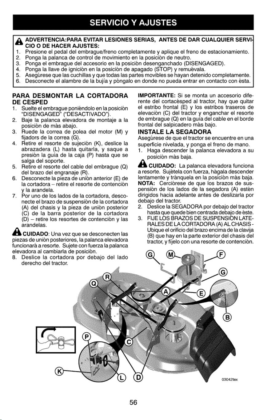
SERVICIO
Y
AJUSTES
A
ClO
O
DE
HACER
AJUSTES:
OarpRano
ADVERTENCIA:PARA
EVITAR
LESIONES
SERIAS,
ANTES
DE
DAR
CUALQUIER
SERVI,
Presione
el
pedal
del
embrague/freno
completamente
y
aplique
el
freno
de
estacionamiento.
Ponga
la
palanca
de
control
de
movimiento
en
la
posicion
de
neutro.
Ponga
el
embrague
del
accesorio
en
la
posicion
desenganchado
(DISENGAGED).
Ponga
la
llave
de
ignicion
en
la
posicion
de
apagado
(STOP)
y
remuevala.
Asegurese
que
las
cuchillas
y
que
todas
las
partes
movibles
se
hayan
detenido
completamente.
Desconecte
el
alambre
de
la
bujfa
y
pongalo
en
donde
no
pueda
entrar
en
contacto
con
esta.
PARA
DESMONTAR
LA
CORTADORA
DE
CESPED
1.
Suelte
el
embrague
poniéndolo
en
la
posicion
“DISENGAGED”
(“DESACTIVADO’).
Baje
la
palanca
elevadora
de
montaje
a
la
posicion
de
mas
abajo.
Ruede
ia
correa
de
poiea
del
motor
(M)
y
fijadors
de
la
correa
(G).
Retire
el
resorte
de
sujecion
(K),
deslice
la
abrazadera
(L)
hasta
quitarla,
y
saque
a
presion
la
guia
de
la
caja
(P)
hasta
que
se
salga
del
soporte.
Retire
el
resorte
del
cable
del
embrague
(Q)
del
brazo
dei
engranaje
(R).
Desconecte
la
pieza
de
union
anterior
(E)
de
la
cortadora
~
retire
el
resorte
de
contencion
y
la
arandela.
Por
uno
de
los
lados
de
la
cortadora,
desco-
necte
el
brazo
de
suspension
de
la
cortadora
(A)
del
chasis
y la
pieza
de
union
posterior
(C)
de
fa
barra
posterior
de
la
cortadora
(D)
—
retire
los
resortes
de
contencion
y
las
arandelas.
2
3.
4
CUIDADO:
Una
vez
que
se
desconecten
las
piezas
de
union
posteriores,
la
palanca
elevadora
funcionara
a
resorte.
Sujete
con
fuerza
la
palanca
elevadora
al
cambiarla
de
posicion.
8.
Deslice
la
cortadora
por
debajo
del
lado
derecho
del
tractor.
f
IMPORTANTE:
Si
se
monta
un
accesorio
dife-
rente
del
cortacésped
al
tractor,
hay
que
quitar
el
estribo
frontal
(E)
y
los
estribos
traseros
de
elevacion
(C)
del
tractor
y
enganchar
el
resorte
de
embrague
(Q)
en
la
guia
del
cable
en
el
borde
frontal
del
salpicadero
mas
bajo.
INSTALE
LA
SEGADORA
Asegirese
de
que
el
tractor
se
encuentre
en
una
superficie
nivelada,
y
ponga
el
freno
de
mano.
1.
Haga
descender
la
palanca
elevadora
a
su
posicion
mas
baja.
CUIDADO:
La
palanca
elevadora
funciona
aresorte.
Sujetela
con
fuerza,
hagala
descender
lentamente
y
tranquela
en
la
posicion
mas
baja.
NOTA:
Cercidrese
de
que
ios
brazos
de
sus-
pension
de
los
lados
de
la
segadora
(A)
esten
dirigidos
hacia
adelante
antes
de
deslizarla
por
debajo
del
tractor.
2.
Deslice
la
SEGADORA
por
debajo
del
tractor
hasta
que
quede
bien
centrada
debajo
de
este.
FIJE
LOS
BRAZOS
DE
SUSPENSION
LATE-
RALES
DE
LA
CORTADORA
(A)
AL
CHASIS
-
Ubique
el
orificio
del
brazo
encima
de
la
clavija
(B)
que
hay
en
Ia
parte
exterior
del
chasis
del
tractor,
y
fijelo
con
una
resorte
de
contencion.
a
3.
03042tex
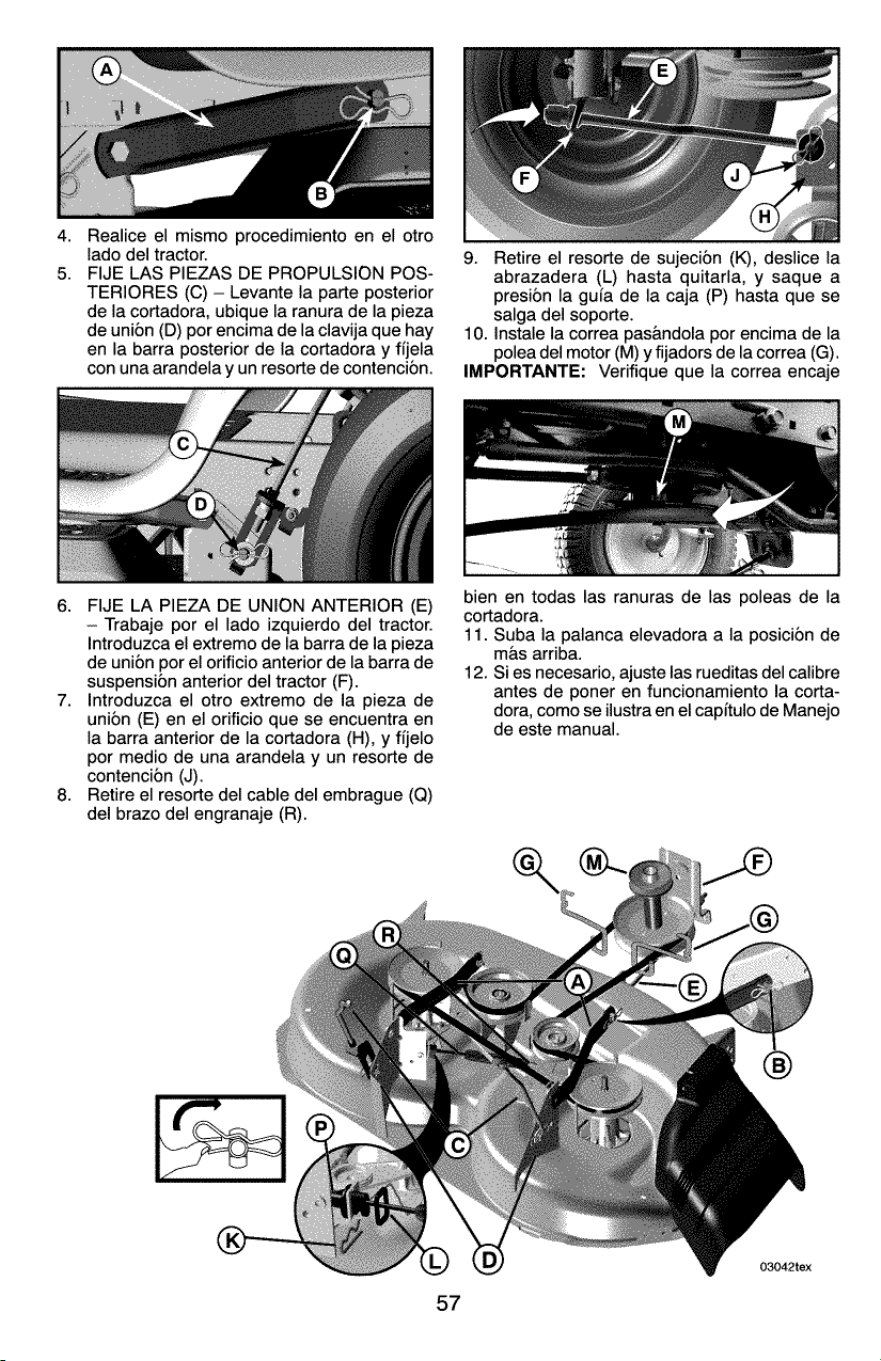
Realice
el
mismo
procedimiento
en
el
otro
lado
dei
tractor.
FIJE
LAS
PIEZAS
DE
PROPULSION
POS-
TERIORES
(C)
—
Levante
fa
parte
posterior
de
fa
cortadora,
ubique
la
ranura
de
la
pieza
de
union
(D)
por
encima
de
la
clavija
que
hay
en
la
barra
posterior
de
la
cortadora
y
fijela
con
una
arandela
y
un
resorte
de
contencion.
9.
Retire
el
resorte
de
sujecion
(K),
deslice
la
abrazadera
(L)
hasta
quitarla,
y
saque
a
presion
la
guia
de
la
caja
(P)
hasta
que
se
salga
del
soporte.
10.
Instale
la
correa
pasandola
por
encima
de
la
polea
del
motor
(M) y
fijadors
de
la
correa
(G).
IMPORTANTE:
Verifique
que
la
correa
encaje
FIJE
LA
PIEZA
DE
UNION
ANTERIOR
(E)
~
Trabaje
por
el
lado
izquierdo
del
tractor.
Introduzca
el
extremo
de
la
barra
de
la
pieza
de
union
por
el
orificio
anterior
de
la
barra
de
suspension
anterior
del
tractor
(F).
Introduzca
el
otro
extremo
de
la
pieza
de
union
(E)
en
el
orificio
que
se
encuentra
en
la
barra
anterior
de
la
cortadora
(H),
y
fijelo
por
medio
de
una
arandela
y
un
resorte
de
contencion
(J).
Retire
el
resorte
del
cable
del
embrague
(Q)
del
brazo
del
engranaje
(R).
bien
en
todas
las
ranuras
de
las
poleas
de
la
cortadora.
11.
Suba
la
palanca
elevadora
a
la
posicion
de
mas
arriba.
12.
Sies
necesario,
ajuste
las
rueditas
del
calibre
antes
de
poner
en
funcionamiento
la
corta-
dora,
como
se
ilustra
en
el
capitulo
de
Manejo
de
este
manual.
03042tex
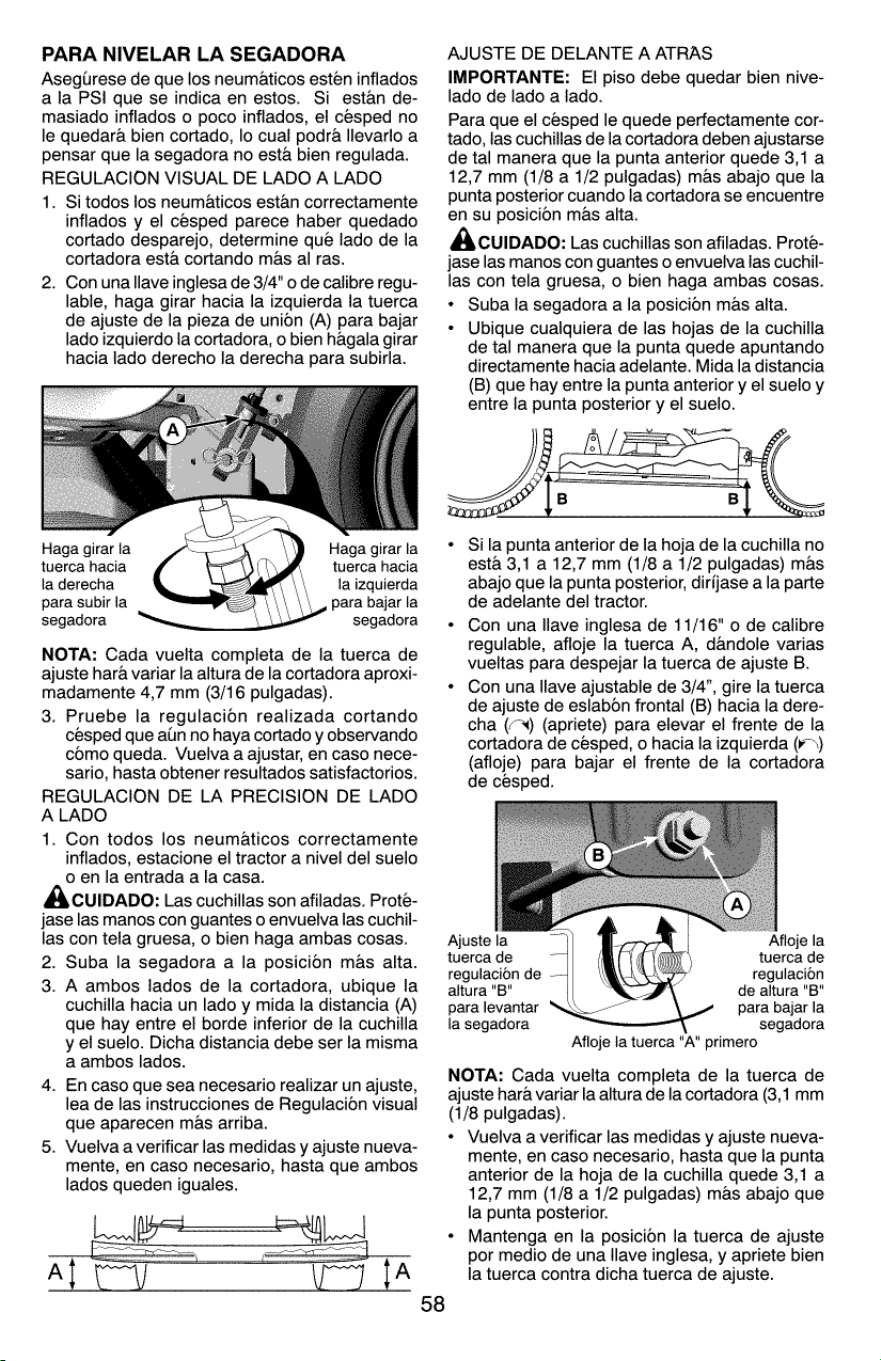
PARA
NIVELAR
LA
SEGADORA
Asegilrese
de
que
los
neumaticos
estén
inflados
ala
PSI
que
se
indica
en
estos.
Si
estan
de-
masiado
inflados
0
poco
inflados,
el
cesped
no
le
quedara
bien
cortado,
lo
cual
podra
llevarlo
a
pensar
que
la
segadora
no
esta
bien
regulada.
REGULACION
VISUAL
DE
LADO
A
LADO
1.
Si
todos
los
neumaticos
estan
correctamente
inflados
y
el
cesped
parece
haber
quedado
cortado
desparejo,
determine
qué
lado
de
la
cortadora
esta
cortando
mas
al
ras.
.
Con
una
llave
inglesa
de
3/4"
0
de
calibre
regu-
lable,
haga
girar
hacia
la
izquierda
la
tuerca
de
ajuste
de
la
pieza
de
union
(A)
para
bajar
lado
izquierdo
la
cortadora,
o
bien
hagala
girar
hacia
lado
derecho
la
derecha
para
subirla.
Haga
girar
la
Haga
girar
la
tuerca
hacia
tuerca
hacia
la
derecha
la
izquierda
para
subir
la
para
bajar
la
segadora segadora
NOTA:
Cada
vuelta
completa
de
ia
tuerca
de
ajuste
hara
variar
la
altura
de
la
cortadora
aproxi-
madamente
4,7
mm
(3/16
pulgadas).
3.
Pruebe
la
regulacion
realizada
cortando
cesped
que
alin
no
haya
cortado
y
observando
como
queda.
Vuelva
a
ajustar, en
caso
nece-
sario,
hasta
obtener
resultados
satisfactorios.
REGULACION
DE
LA
PRECISION
DE
LADO
ALADO
1.
Con
todos
los
neumaticos
correctamente
inflados,
estacione
el
tractor
a
nivel
del
suelo
o
en
la
entrada
a
la
casa.
CUIDADO:
Las cuchillas
son
afiladas.
Prote-
jase
las
manos
con
guantes
o
envuelva
las
cuchil-
las
con
tela
gruesa,
o
bien
haga
ambas
cosas.
2.
Suba
la
segadora
a
la
posicion
mas
alta.
3.
A
ambos
lados
de
la
cortadora,
ubique
la
cuchilla
hacia
un
lado
y
mida
ia
distancia
(A)
que
hay
entre
el
borde
inferior
de
la
cuchilla
y
el
suelo.
Dicha
distancia
debe
ser
la
misma
a
ambos
lados.
.
En
caso
que
sea
necesario
realizar
un
ajuste,
lea
de
las
instrucciones
de
Regulacion
visual
que
aparecen
mas
arriba.
.
Vuelva
a
verificar
las
medidas
y
ajuste
nueva-
mente,
en
caso
necesario,
hasta
que
ambos
lados
queden
iguales.
|
Al
yA
58
AJUSTE
DE
DELANTE
A
ATRAS
IMPORTANTE:
El
piso
debe
quedar
bien
nive-
lado
de
lado
a
lado.
Para
que
el
cesped
le
quede
perfectamente
cor-
tado,
las
cuchillas
de
la
cortadora
deben
ajustarse
de
tal
manera
que
la
punta
anterior
quede
3,1
a
12,7
mm
(1/8
a
1/2
pulgadas)
mas
abajo
que
la
punta
posterior
cuando
la
cortadora
se
encuentre
en
su
posicion
mas
alta.
Acuipapo:
Las
cuchillas
son
afiladas.
Prote-
jase
las
manos
con
guantes
o
envueiva
las
cuchil-
las
con
tela
gruesa,
o
bien
haga
ambas
cosas.
*
Suba
la
segadora
a
la
posicion
mas
alta.
«
Ubique
cualquiera
de
las
hojas
de
la
cuchilla
de
tal
manera
que
la
punta
quede
apuntando
directamente
hacia
adelante.
Mida
la
distancia
(B)
que
hay
entre
la
punta
anterior
y
el
suelo
y
entre
la
punta
posterior
y
el
suelo.
Si
la
punta
anterior
de
la
hoja
de
la
cuchilla
no
esta
3,1
a
12,7
mm
(1/8
a
1/2
pulgadas)
mas
abajo
que
la
punta
posterior,
dirfjase
a
la
parte
de
adelante
del
tractor.
Con
una
llave
inglesa
de
11/16"
o
de
calibre
regulable,
afloje
la
tuerca
A,
dandole
varias
vueltas
para
despejar
ia
tuerca
de
ajuste
B.
Con
una
llave
ajustable
de
3/4”,
gire
la
tuerca
de
ajuste
de
eslabon
frontal
(B)
hacia
la
dere-
cha
(-\)
(apriete)
para
elevar
ei
frente
de
la
cortadora
de
cesped,
o
hacia
la
izquierda
(>)
{afloje)
para
bajar
el
frente
de
la
cortadora
de
cesped.
Ajuste
la
Afloje
la
tuerca
de
tuerca
de
regulacion
de
-
reguiacion
altura
"B"
de
altura
"B"
para
levantar
para
bajar
la
la
segadora
segadora
Afloje
la
tuerca
"A"
primero
NOTA:
Cada
vuelta
completa
de
la
tuerca
de
ajuste
hara
variar
la
altura
de
la
cortadora
(3,1
mm
(1/8
pulgadas).
+
Vuelva
a
verificar
las
medidas
y
ajuste
nueva-
mente,
en
caso
necesario,
hasta
que
la
punta
anterior
de
la
hoja
de
la
cuchilla
quede
3,1
a
12,7
mm
(1/8
a
1/2
pulgadas)
mas
abajo
que
la
punta
posterior.
Mantenga
en
la
posicion
la
tuerca
de
ajuste
por
medio
de
una
llave
inglesa,
y
apriete
bien
la
tuerca
contra
dicha
tuerca
de
ajuste.
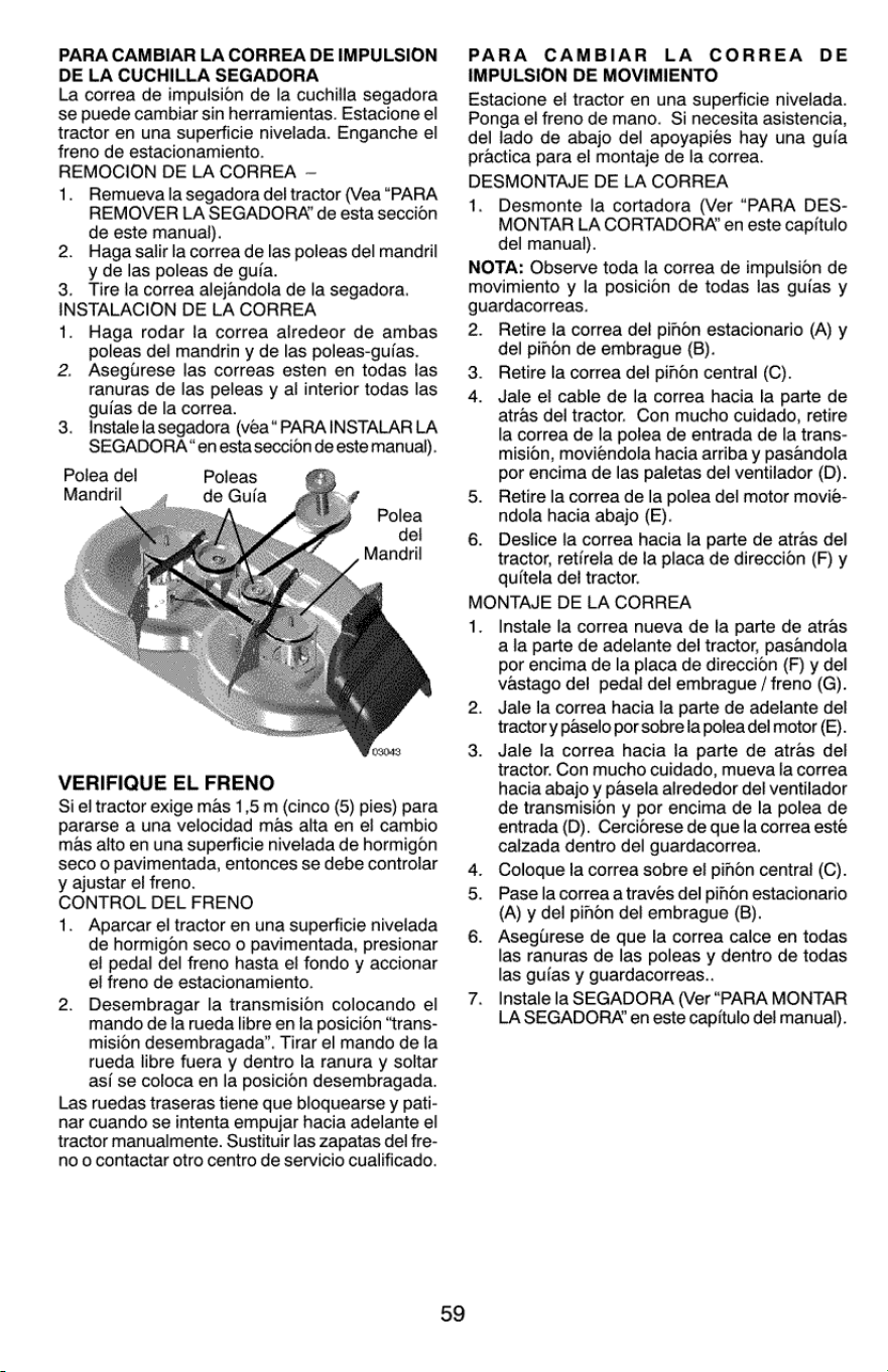
PARA
CAMBIAR
LA
CORREA
DE
IMPULSION
DE LA
CUCHILLA
SEGADORA
La
correa
de
impulsion
de
la
cuchilla
segadora
se
puede
cambiar
sin
herramientas.
Estacione
el
tractor
en
una
superficie
nivelada.
Enganche
el
freno
de
estacionamiento.
REMOCION
DE
LA
CORREA
—
1.
Remueva
la
segadora
de!
tractor
(Vea
“PARA
REMOVER
LA
SEGADORA’
de
esta
seccion
de
este
manual).
Haga
salir
la
correa
de
las
poleas
del
mandril
y
de
las
poleas
de gufa.
3.
Tire
la
correa
alejandoia
de
la
segadora.
INSTALACION
DE
LA
CORREA
1.
Haga
rodar
la
correa
alredeor
de
ambas
poleas
del
mandrin
y
de
las
poleas-guias.
Asegturese
las
correas
esten
en
todas
las
ranuras
de
las
peleas
y
al
interior
todas
las
guias
de
la
correa.
Instale
la
segadora
(vea“
PARAINSTALARLA
SEGADORA
“
enesta
seccion
de
este
manual).
Polea
del
Manaril
2.
2.
3.
Poleas
de
Guia
Polea
dei
Manaril
VERIFIQUE
EL
FRENO
Si
el
tractor
exige
mas
1,5
m
(cinco
(5)
pies)
para
pararse
a
una
velocidad
mas
alta
en
el
cambio
mas
alto
en
una
superficie
nivelada
de
hormigon
seco
0
pavimentada,
entonces
se
debe
controlar
y
ajustar
el
freno.
CONTROL
DEL
FRENO
1.
Aparcar
el
tractor
en
una
superficie
nivelada
de
hormigon
seco
o
pavimentada,
presionar
el
pedal
del
freno
hasta
el
fondo
y
accionar
el
freno
de
estacionamiento.
Desembragar
la
transmision
colocando
el
mando
de
la
rueda
libre
en
la
posicion
“trans-
mision
desembragada”.
Tirar
el
mando
de
ja
rueda
libre
fuera
y
dentro
la
ranura
y
soltar
as/
se
coloca
en
la
posicion
desembragada.
Las
ruedas
traseras
tiene
que
bloquearse
y
pati-
nar
cuando
se
intenta
empujar
hacia
adelante
el
tractor
manualmente.
Sustituir
las
zapatas
del
fre-
no
o
contactar
otro
centro
de
servicio
cualificado.
59
PARA
CAMBIAR
LA
CORREA
DE
IMPULSION
DE
MOVIMIENTO
Estacione
el
tractor
en
una
superficie
nivelada.
Ponga
el
freno
de
mano.
Si
necesita
asistencia,
del
lado
de
abajo
del
apoyapiés
hay
una
guia
practica
para
el
montaje
de
la
correa.
DESMONTAJE
DE
LA
CORREA
1.
Desmonte
la
cortadora
(Ver
“PARA
DES-
MONTAR
LA
CORTADORA
en
este
capitulo
del
manual).
NOTA:
Observe
toda
la
correa
de
impulsion
de
movimiento
y la
posicion
de
todas
las
guias
y
guardacorreas.
2.
Retire
la
correa
dei
pihon
estacionario
(A)
y
del
pinon
de
embrague
(B).
Retire
la
correa
del
pihon
central
(C).
Jale
el
cable
de
la
correa
hacia
la
parte
de
atras
del
tractor.
Con
mucho
cuidado,
retire
la
correa
de
la
polea
de
entrada
de
la
trans-
mision,
moviendola
hacia
arriba
y
pasandola
por
encima
de
las
paletas
del
ventilador
(D).
3.
4.
5.
Retire
la
correa
de
la
polea
del
motor
movie-
ndola
hacia
abajo
(E).
6.
Deslice
la
correa
hacia
la
parte
de
atras
del
tractor,
retirela
de
la
placa
de
direccion
(F)
y
quitela
del
tractor.
MONTAJE
DE
LA
CORREA
1.
Instale
la
correa
nueva
de
la
parte
de
atras
a
la
parte
de
adelante
del
tractor,
pasandola
por
encima
de
la
placa
de
direccion
(F)
y
del
vastago
del
pedal
del
embrague
/
freno
(G).
Jale
la
correa
hacia
ia
parte
de
adelante
del
tractor
y
paselo
por
sobre
la
polea
del
motor
(E).
Jale
la
correa
hacia
la
parte
de
atras
del
tractor.
Con
mucho
cuidado,
mueva
la
correa
hacia
abajo
y
pasela
alrededor
del
ventilador
de
transmision
y
por
encima
de
la
polea
de
entrada
(D).
Cerciorese
de
que
la
correa
esté
calzada
dentro
del
guardacorrea.
Coloque
Ia
correa
sobre
el
pinon
central
(C).
Pase
la
correa
a
traves
del
pinon
estacionario
(A)
y
del
pinon
del
embrague
(B).
Asegirese
de
que
la
correa
calce
en
todas
las
ranuras
de
las
poleas
y
dentro
de
todas
las
guias
y
guardacorreas..
Instale
la
SEGADORA
(Ver
“PARA
MONTAR
LA
SEGADORA
en
este
capitulo
del
manual).
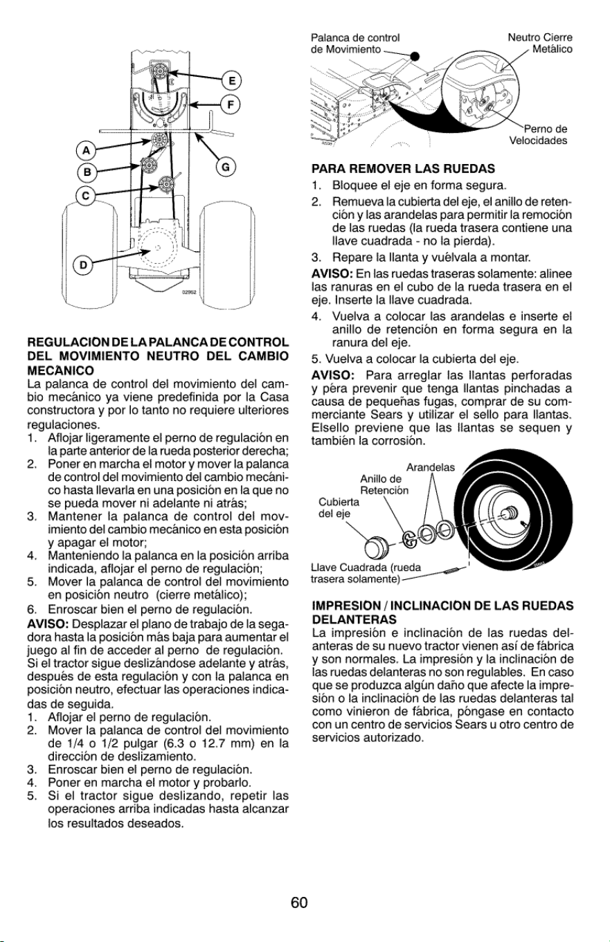
REGULACION
DELAPALANCA
DE
CONTROL
DEL
MOVIMIENTO
NEUTRO
DEL
CAMBIO
MECANICO
La
palanca
de
control
del
movimiento
del
cam-
bio
mecanico
ya
viene
predefinida
por
la
Casa
constructora
y
por
lo
tanto
no
requiere
ulteriores
regulaciones.
1.
Aflojar
ligeramente
el
perno
de
regulacion
en
la
parte
anterior
de
la
rueda
posterior
derecha;
Poner
en
marcha
el
motor
y
mover
la
palanca
de
control
del
movimiento
del
cambio
mecani-
co
hasta
llevarla
en
una
posicion
en
la
que
no
se
pueda
mover
ni
adelante
ni
atras;
Mantener
la
palanca
de
control
del
mov-
imiento
del
cambio
mecanico
en
esta
posicion
y
apagar
el
motor;
Manteniendo
la
palanca
en
la
posicion
arriba
indicada,
aflojar
el
perno
de
regulaci6n;
Mover
la
palanca
de
control
del
movimiento
en
posicion
neutro
(cierre
metalico);
6.
Enroscar
bien
el
perno
de
regulacion.
AVISO:
Desplazar
el
plano
de
trabajo
de
la
sega-
dora hasta
la
posicion
mas
baja
para
aumentar
el
juego
al
fin
de
acceder
al
perno
de
regulacion.
Si
el
tractor
sigue
deslizandose
adelante
y
atras,
después
de
esta
regulacion
y
con
la
palanca
en
posicion
neutro,
efectuar
las
operaciones
indica-
das
de
seguida.
1.
Aflojar
el
perno
de
regulacion.
2.
4.
5.
2.
Mover
la
palanca
de
control
del
movimiento
de
1/4
o
1/2
pulgar
(6.3
0
12.7
mm)
en
la
direccion
de
deslizamiento.
3.
Enroscar
bien
el
perno
de
regulacion.
4.
Poner
en
marcha
el
motor
y
probarlo.
5.
Si
el
tractor
sigue
deslizando,
repetir
las
operaciones
arriba
indicadas
hasta
alcanzar
los
resultados
deseados.
60
Palanca
de
control
Neutro
Cierre
de
Movimiento
Metalico
:
°
Perno
de
are
Velocidades
PARA
REMOVER
LAS
RUEDAS
1.
Bloquee
el
eje
en
forma
segura.
2.
Remuevala
cubierta
del
eje,
el
anillo
de
reten-
cion
y
las
arandelas
para
permitir
la
remocion
de
las
ruedas
(la
rueda
trasera
contiene
una
llave
cuadrada
-
no
la
pierda).
3.
Repare
la
llanta
y
vuelvala
a
montar.
AVISO:
En
las
ruedas
traseras
solamente:
alinee
las
ranuras
en
el
cubo
de
la
rueda
trasera
en
el
eje.
Inserte
la
llave
cuadrada.
4.
Vuelva
a
colocar
las
arandelas
e
inserte
el
anillo
de
retencion
en
forma
segura
en
la
ranura
del
eje.
5.
Vuelva
a
colocar
la
cubierta
del
eje.
AVISO:
Para
arreglar
las
llantas
perforadas
y
pera
prevenir
que
tenga
llantas
pinchadas
a
causa
de
pequenas
fugas,
comprar
de
su
com-
merciante
Sears
y
utilizar
el
sello
para
llantas.
Elsello
previene
que
las
llantas
se
sequen
y
también
la
corrosion.
Arandelas
Anillo
de
Retencion
Cubierta
del
eje
Llave
Cuadrada
(tueda
ee
trasera
solamente)
IMPRESION
/
INCLINACION
DE
LAS
RUEDAS
DELANTERAS
La
impresion
e
inclinacion
de
las
ruedas
del-
anteras
de
su
nuevo
tractor
vienen
asf
de
fabrica
y
son
normales.
La
impresion
y
la
inclinacion
de
las
ruedas
delanteras
no
son
regulables.
En
caso
que
se
produzca
aigtin
daho
que
afecte
la
impre-
sion
o
la
inclinacion
de
las
ruedas
delanteras
tal
como
vinieron
de
fabrica,
pongase
en
contacto
con
un
centro
de
servicios
Sears
u
otro
centro
de
servicios
autorizado.
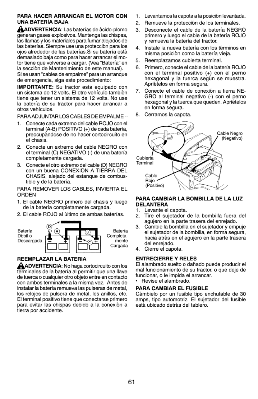
PARA
HACER
ARRANCAR
EL
MOTOR
CON
UNA
BATERIA
BAJA
AADVERTENCIA:
Las
baterias
de
acido-plomo
generan
gases
explosivos.
Mantenga
las
chispas,
las
llamas
y
los
materiales
para
fumar
alejados
de
las
baterias.
Siempre
use
una
proteccion
para
los
ojos
alrededor
de
las
baterias.Si
su
bateria
esta
demasiado
baja
como
para
hacer
arrancar
el
mo-
tor
tiene
que
volverse
a
cargar.
(Vea
“Bateria”
en
la
seccion
de
Mantenimiento
de
este
manual).
Si
se
usan
“cables
de
empalme”
para
un
arranque
de
emergencia,
siga
este
procedimiento:
IMPORTANTE:
Su
tractor
esta
equipado
con
un
sistema
de
12
volts.
El
otro
vehiculo
tambien
tiene
que
tener
un
sistema
de
12
volts.
No
use
la
baterfa
de
su
tractor
para
hacer
arrancar
a
otros
vehiculos.
PARAADJUNTAR
LOS
CABLES
DE
EMPALME
—
1.
Conecte
cada
extremo
del
cable
ROJO
con
el
terminal
(A-B)
POSITIVO
(+)
de
cada
bateria,
preocupandose
de
no
hacer
cortocircuito
en
el
chasis.
Conecte
un
extremo
del
cable
NEGRO
con
el
terminal
(C)
NEGATIVO
(-)
de
una
bateria
completamente
cargada.
Conecie
el
otro
extremo
del
cable
(D)
NEGRO
con
un
buena
CONEXION
A
TIERRA
DEL
CHASIS,
alejado
del
estanque
de
combus-
tible
y
de
la
bateria.
PARA
REMOVER
LOS
CABLES,
INVIERTA
EL.
ORDEN
1.
El
cable
NEGRO
primero
del
chasis
y
luego
de
la
bateria
completamente
cargada.
2.
El
cable
ROJO
al
Ultimo
de
ambas
baterias.
Bateria
Bateria
Debil
o
Compieta-
Descargada
mente
Cargada
REEMPLAZAR
LA
BATERIA
AADVERTENCIA:
No
haga
cortocircuito
con
los
terminales
de
la
baterfa
al
permitir
que
una
llave
de
tuerca
o
cualquier
otro
objeto
entre
en
contacto
con
ambos
terminales
aia
misma
vez.
Antes
de
instalar
la
bater’a
remueva
las
pulseras
de
metal,
los
relojes
de
pulsera
de
metal,
los
anillos,
etc.
El
terminal
positivo
tiene
que
conectarse
primero
para
evitar
las
chispas
debido
a
la
conexion
a
tierra
por
accidente.
61
Levantamos
la
capota
a
la
posicion
levantada.
2.
Remueve
la
proteccion
de
los
terminales.
3.
Desconecte
el
cable
de
la
baterfa
NEGRO
primero
y
luego
el
cable
de
la
bateria
ROJO
y
remueva
la
bateria
del
tractor.
4.
Instale
la
nueva
bateria con
los
terminos
en
misma
posicion
como
la
bateria
vieja.
5.
Reemplazamos
cubierta
terminal.
6.
Primero,
conecte
el
cable
de
la
bateria
ROJO
con
el
terminal
positivo
(+)
con
el
perno
hexagonal
y
la
tuerca
segun
se
muestra.
Aprietelos
en
forma
segura.
7.
Conecte
el
cable
de
conexion
a
tierra
NE-
GRO
al
terminal
negativo
(-)
con
el
perno
hexagonal
y
la
tuerca
que
queden.
Apriételos
en
forma
segura.
8.
Cerramos
la
capota.
Cable
Negro
(Negativo)
Cubierta
Terminal
Cable
Rojo
(Positivo)
PARA
CAMBIAR
LA
BOMBILLA
DE LA
LUZ
DELANTERA
1.
Levante
el
capota.
2.
Tire
el
sujetador
de
la
bombilla
fuera
del
agujero
en
la
parte
trasera
del
enrejado.
Cambie
la
bombilla
en
el
sujetador
y
empuje
el
sujetador
de
la
bombilla,
en
forma
segura,
hacia
atras
en
el
agujero
en
la
parte
trasera
del
enrejado.
4.
Cierre
el
capota.
ENTRECIERRE
Y
RELES
El
alambrado
suelto
o
danado
puede
producir
el
mal
funcionamiento
de
su
tractor,
o
que
deje
de
funcionar,
o
le
impida
el
arrancar.
*
Revise
el
alambrado.
PARA
CAMBIAR
EL
FUSIBLE
Cambielo
por
un
fusible
tipo
enchufable
de 30
amps,
tipo
automotriz.
El
sujetador
del
fusible
esta
ubicado
detras
del
tablero.
3.
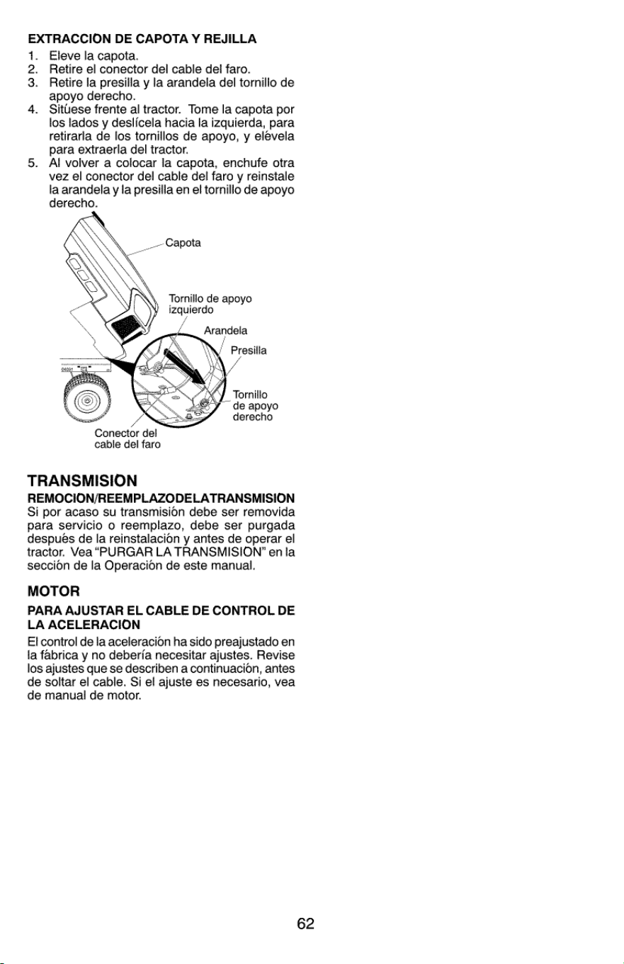
EXTRACCION
DE
CAPOTA
Y
REJILLA
1.
Eleve
la
capota.
2.
Retire
el
conector
del
cable
del
faro.
3.
Retire
ja
presilla
y
la
arandela
del
tornillo
de
apoyo
derecho.
4.
Situese
frente
al
tractor.
Tome
la
capota
por
los
lados
y
deslicela hacia
la
izquierda,
para
retirarla
de
los
tornillos
de
apoyo,
y
elevela
para extraerla
del
tractor.
5.
Al
volver
a
colocar
la
capota,
enchufe
otra
vez
el
conector
del
cable
del
faro
y
reinstale
la
arandela
y la
presilla
en
el
tornillo
de
apoyo
derecho.
_-~
Capota
Tornillo
de
apoyo
izquierdo
*
|
Tornillo
J
de
apoyo
derecho
Conector
del
cable
del
faro
TRANSMISION
REMOCION/REEMPLAZODELATRANSMISION
Si
por
acaso
su
transmision
debe
ser
removida
para
servicio
o
reemplazo,
debe
ser
purgada
después
de
la
reinstalacion
y
antes
de
operar
el
tractor.
Vea
“PURGAR
LA
TRANSMISION’
en
la
seccion
de
la
Operacion
de
este
manual.
MOTOR
PARA
AJUSTAR
EL
CABLE
DE
CONTROL
DE
LA
ACELERACION
Et
control
de
la
aceleracion
ha
sido
preajustado
en
la
fabrica
y
no
deberia
necesitar
ajustes.
Revise
los
ajustes
que
se
describen
a
continuacion,
antes
de
soltar
el
cable.
Si
el
ajuste
es
necesario,
vea
de
manual
de
motor.
62
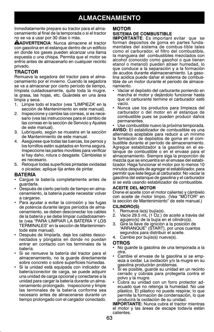
ALMACENAMIENTO
Inmediatamente
prepare
su
tractor
para
el
alma-
cenamiento
al
final
de
la
temporada
o
si
el
tractor
no
sé
va
a
usar
por
30
dias
o
mas.
AADVERTENCIA:
Nunca
almacene
e!
tractor
con
gasolina
en
el
estanque
dentro
de
un edificio
en
donde
los
gases
pueden
alcanzar
una
llama
expuesta
o
una
chispa.
Permita
que
el
motor
se
enfrie
antes
de
almacenarlo
en
cualquier
recinto
privado.
TRACTOR
Remueva
la
segadora
del
tractor
para
el
alma-
cenamiento
por
el
invierno.
Cuando
la
segadora
se
va
a
almacenar
por
cierto
periodo
de
tiempo,
limpiela
cuidadosamente,
quite
toda
la
mugre,
la
grasa,
las
hojas,
etc.
Guardela
en
una
area
limpia
y
seca.
1.
Limpie
todo
el
tractor
(vea
“LIMPIEZA’
en
la
seccion
de
Mantenimiento
en
este
manual).
Inspeccione
y
cambie
las
correas,
si
es
nece-
sario
(vea
las
instrucciones
para
el
cambio
de
las
correas
en
la
seccion
de
Servicio
y
Ajustes
de
este
manual).
Lubriquelo,
segin
se
muestra
en
la
seccion
de
Mantenimiento
de
este
manual.
Asegurese
que
todas
las
tuercas,
los
pernos
y
los
tornillos
esten
sujetados
en
forma
segura.
Inspeccione
las
partes
movibles
para
verificar
si
hay
dano,
rotura
o
desgaste.
Cambielas
si
es
necesario.
Retoque
todas
superficies
pintadas
oxidadas
o
picadas;
aplique
lija
antes
de
pintar.
BATERIA
*
Cargue
la
bateria
completamente
antes
de
guardarla.
Después
de
cierto
periodo
de
tiempo
en
alma-
cenamiento,
la
bateria
puede
necesitar
volver
a
cargarse.
Para
ayudar
a
evitar
la
corrosion
y
las
fugas
de
potencia
durante
largos
periodos
de
alma-
cenamiento,
se
deben desconectar
los
cables
de
la
bateria
y
se
debe
limpiar
cuidadosamen-
te
(vea
“PARA
LIMPIAR
LA
BATERIA
Y
LOS
TERMINALES’
en
ia
seccion
de
Mantenimien-
tode
este
manual).
Después
de
limpiarla,
deje
los
cables
desco-
nectados
y
pongalos
en
donde
no
puedan
entrar
en
contacto
con
los
terminales
de
la
bateria.
Si
se
remueve
la
bateria
del
tractor
para
el
almacenamiento,
no
la
guarde
directamente
sobre
concreto
o
sobre
superficies
humedas.
Si
la
unidad
esta
equipada
con
indicador
de
bateria/conector
de
carga,
se
puede
adquirir
una
unidad
de
carga
opcional
y
conectarse
ala
unidad
para
cargar
la
bateria
durante
un
alma-
cenamiento
prolongado.
Inspeccione
y
limpie
ias
terminales
de
la
bateria
conforme
sea
necesario
antes
de
almacenarse
durante
un
tiempo
prolongado
con
el
cargador
conectado.
5.
63
MOTOR
SISTEMA
DE
COMBUSTIBLE
IMPORTANTE:
Es
important
evitar
que
se
forman
depositos
de
goma
en
partes
funda-
mentales
del
sistema
de
combus-tible
tales
como
el
carburador,
el
filtro
del
combustible,
la
manguera
del
combustibles
mezclados
con
alcohol
(conocido
como
gasohol
o
que
tienen
etanol
o
metanol)
pueden
atraer
humedad,
io
que
conduce
a
la
separacion
y
a
la
formacion
de
acudos
durante
elalmacenamiento.
La
gaso-
lina
acidica
puede
danar
el
sistema
de
combus-
tible
de
un
motor
durante
el
periodo
de
almace-
namiento.
«
Vaciar
el
deposito
del
carburante
poniendo
en
marcha
el
motor
y
dejandolo
funcionar
hasta
que
el
carburante
termine
el
carburador
este
vacio.
Nunca
use
los
productos
para
limpieza
del
carburador
o
del
motor
en
el
estanque
de
combustible
pues
se
pueden
producir
dahos
permanentes.
*
Use
combustible nuevo
la
proxima
temporada.
AVISO:
El!
estabilizador
de
combustible
es
una
alternativa
aceptable
para
reducir
a
un
minimo
la
formacion
de
depositos
de
goma
en
el
com-
bustible
durante
el
periodo
de
almacenamiento.
Agregue
estabilizador
a
la
gasolina
en
el
es-
tanque
de
combustible
o
en
el
envase
para
el
almacenamiento.
Siempre
siga
la
proporcion
de
mezcla
que
se
encuentra
en
el
envase
del
estabi-
lizador.
Haga
funcionar
el
motor
por
lo
menos
10
minutos
despues
de
agregar
el
estabilizador,
para
permitir
que
este
flegue
al
carburador.
No
vaciar
la
gasolina
del
estanque
de
gasolina
y
el
carburador
si
se
esta
usando
estabilizador
de
combustible.
ACEITE
DEL
MOTOR
Drene
el
aceite
(con
ei
motor
caliente)
y
cambielo
con
aceite
de
motor
limpio.
(Vea
“MOTOR?”
en
la
seccion
de
Mantenimiento”
de
este
manual.)
CILINDRO(S)
Remueva
la(s)
bujia(s).
2
Vacie
29.5
mL
(1
Oz.)
de
aceite
a
traves
del
agujero(s)
de
la
bujfa
en
el
cilindro(s).
3.
Gire
la
lave
de
ignicion
a
la
posicion
de
“ARRANQUE”
(START),
por
unos
cuantos
segundos
para
distribuir
el
aceite.
4.
Cambie
por
bujia(s)
nueva(s).
OTROS
*
No
guarde
la
gasolina
de
una
temporada
a
la
otra.
Cambie
el
envase
de
la
gasolina
si
se
emp-
ieza
a
oxidar.
La
oxidacion
y/o
la
mugre
en
su
gasolina
produciran
problemas.
Si
es
posible,
guarde
su
unidad
en
un
recinto
cerrado
y
clibrala
para
protegerla
contra
el
poivo
y
la
mugre.
Cubra
su
unidad
con
un forro
protector
ad-
ecuado
que
no
retenga
la
humedad.
No
use
plastico.
El
plastico
no
puede
respirar,
lo
que
permite
la
formacion
de
condensacion,
lo
que
producira
fla
oxidacion
de
su
unidad.
IMPORTANTE:
Nunca
cubra
el
tractor
mientras
el
motor
y
las
areas
de
escape
todavia
estan
calientes.
.
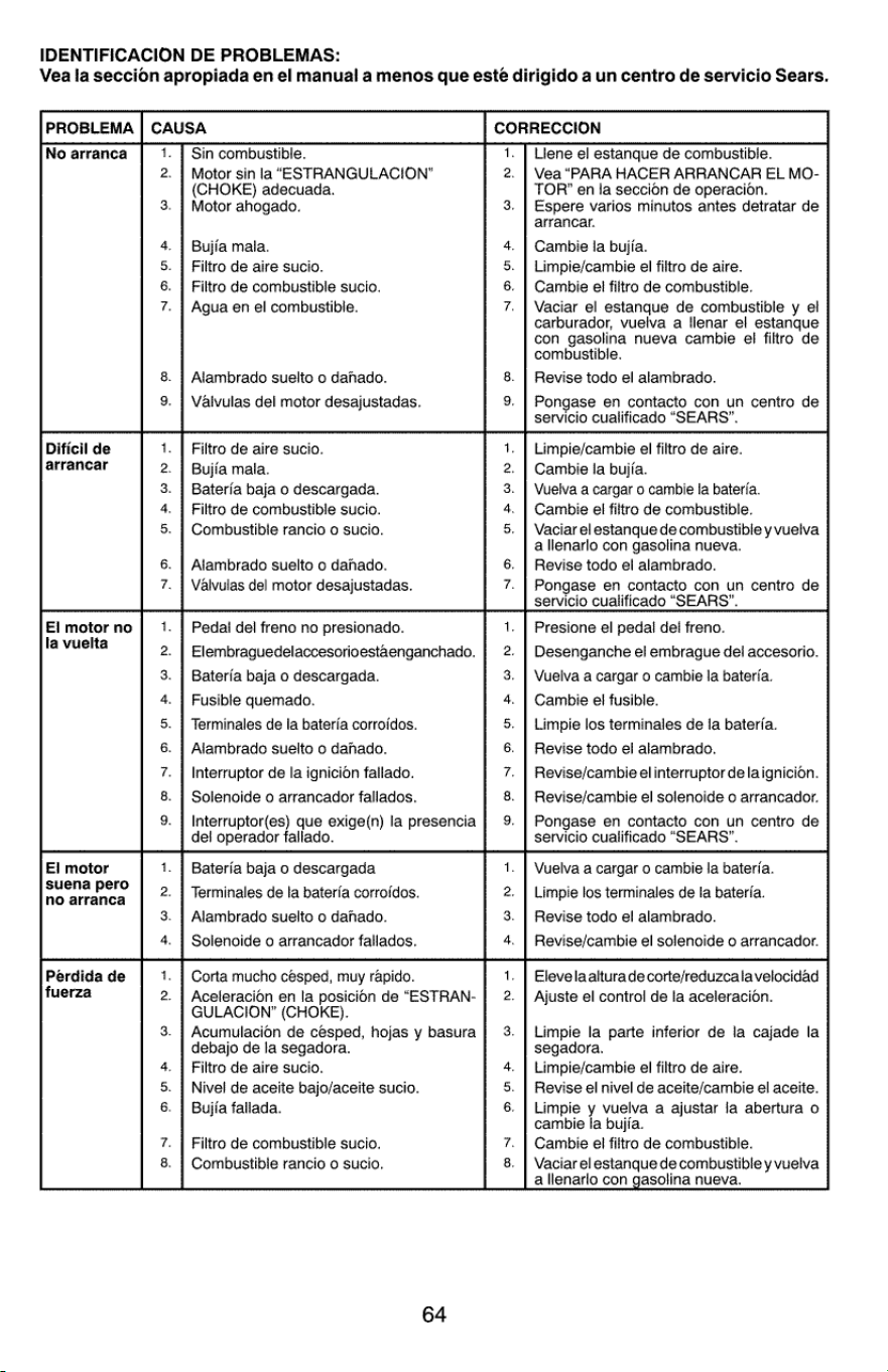
IDENTIFICACION
DE
PROBLEMAS:
Vea
la
seccion
apropiada
en
el
manual
a
menos
que
esteé
dirigido
a
un
centro
de
servicio
Sears.
PROBLEMA
|
CAUSA
CORRECCION
No
arranca
1.
|
Sin
combustible.
1.
Llene
el
estanque
de
combustible.
2.
|
Motor
sin
la
“ESTRANGULACION”
2.
|
Vea
“PARA
HACER
ARRANCAR
EL
MO-
(CHOKE)
adecuada.
TOR’
en
la
seccion
de
operacion.
3.
|
Motor
ahogado.
3.
|
Espere
varios
minutos
antes
detratar
de
arrancar.
4.
|
Bujia
mala.
4.
|
Cambie
la
bujia.
5.
|
Filtro
de
aire
sucio.
5.
|
Limpie/cambie
el
filtro
de
aire.
6.
|
Filtro
de
combustible
sucio.
6.
|
Cambie
el
filtro
de
combustible.
7.
|
Agua
en
el
combustible.
7.
|
Vaciar
el
estanque
de
combustible
y
el
carburador,
vuelva
a
llenar
el
estanque
con
gasolina
nueva
cambie
el
filtro
de
combustible.
8.
|
Alambrado
suelto
o
dahado.
8.
|
Revise
todo
el
alambrado.
9.
|
Valvulas
del
motor
desajustadas.
9.
|
Pongase
en
contacto
con
un
centro
de
servicio
cualificado
“SEARS”.
Dificil
de
1.
|
Filtro
de
aire
sucio.
1.
|
Limpie/cambie
el
filtro
de
aire.
arrancar
2.
|
Bujia
mala.
2.
|
Cambie
la
bujfa.
3.
|
Bateria
baja
o
descargada.
3.
|
Vuelva
a
cargar
o
cambie
la
bateria.
4.
|
Filtro
de
combustible
sucio.
4.
|
Cambie
el
filtro
de
combustible.
5.
|
Combustible
rancio
o
sucio.
5.
|
Vaciar
el
estanque
de
combustible
y
vuelva
a
lienarlo
con
gasolina
nueva.
6.
|
Alambrado
suelto
0
dahado.
6.
|
Revise
todo
el
alambrado.
7.
|
Valvulas
del
motor
desajustadas.
7.
|
Pongase
en
contacto
con
un
centro
de
servicio
cualificado
“SEARS”.
El
motor
no
1.
|
Pedal
del
freno
no
presionado.
1.
|
Presione
el
pedal
dei
freno.
la
vuelta
2.
|
Elembraguedelaccesorioestaenganchado.
2.
|
Desenganche
el
embragque
del
accesorio.
3.
|
Baterfa
baja
o
descargada.
3.
|
Vuelva
a
cargar
o
cambie
la
bateria.
4.
|
Fusible
quemado.
4.
|
Cambie
el
fusible.
5.
|
Terminales
de
la
bateria
corrofdos.
5.
|
Limpie
los
terminales
de
la
bateria.
6.
|
Alambrado
suelto
o
dahado.
6.
|
Revise
todo
el
alambrado.
7.
|
Interruptor
de
la
ignicion
fatlado.
7.
|
Revise/cambie
el
interruptor
de
laignicion.
8.
|
Solenoide
o
arrancador
fallados.
8.
|
Revise/cambie
el
solenoide
o
arrancador.
9.
]
Interruptor(es)
que
exige(n)
la
presencia
|
9.
|
Pongase
en
contacto
con
un
centro
de
del
operador
fallado.
servicio
cualificado
“SEARS”.
El
motor
1.
|
Bateria
baja
o
descargada
1.
|
Vuelva
a
cargar
o
cambie
la
bateria.
suena
pero
:
P :
as
.
:
no
arranca
2.
| Terminales
de
la
bateria
corroidos.
2.
|
Limpie
los
terminales
de
Ia
bateria.
3.
|
Alambrado
suelto
o
dahado.
3.
|
Revise
todo
el
alambrado.
4.
|
Solenoide
o
arrancador
fallados.
4.
|
Revise/cambie
el
solenoide
o
arrancador.
Perdida
de
1.
|
Corta
mucho
cesped,
muy
rapido.
1.
|
Elevelaalturade
corte/reduzcalavelocidad
fuerza
2.
|
Aceleracion
en
la
posicion
de
“ESTRAN-
|
2.
|
Ajuste
el
control
de
la
aceleracion.
GULACION”
(CHOKE).
3.
|
Acumulacion
de
césped,
hojas
y
basura
|
3.
|
Limpie
la
parte
inferior
de
la
cajade
la
debajo
de
la
segadora.
segadora.
4.
|
Filtro
de
aire
sucio.
4.
|
Limpie/cambie
el
filtro
de
aire.
5.
|
Nivel
de
aceite
bajo/aceite
sucio.
5.
|
Revise
el
nivel
de
aceite/cambie
el
aceite.
6.
|
Bujfa
fallada.
6.
|
Limpie
y
vuelva
a
ajustar
ja
abertura
o
cambie
la
bujia.
7.
|
Filtro
de
combustible
sucio.
7.
|
Cambie
el
filtro
de
combustible.
8.
|
Combustible
rancio
o
sucio.
8.
|
Vaciar
el
estanque
de
combustible
y
vuelva
a
llenarlo
con
gasolina
nueva.
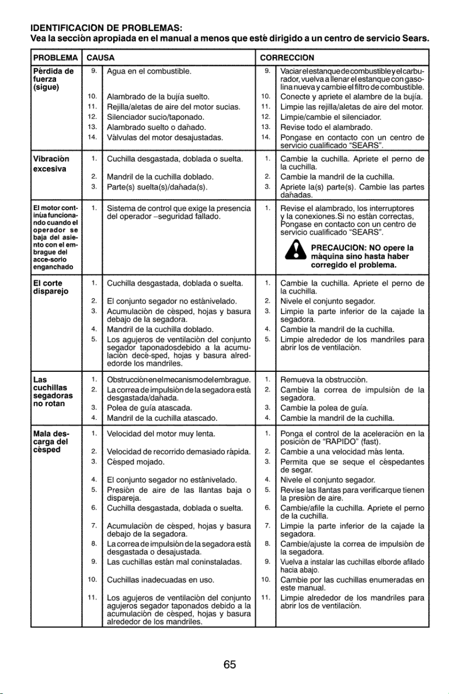
IDENTIFICACION
DE
PROBLEMAS:
Vea
la
seccion
apropiada
en
el
manual
a
menos
que
esté
dirigido
a
un
centro
de
servicio
Sears.
Los
agujeros
de
ventilacion
del
conjunto
agujeros
segador
taponados
debido
a
la
acumulacion
de
cesped,
hojas
y
basura
alrededor
de
los
mandfriles.
14.
PROBLEMA
|
CAUSA
CORRECCION
Perdida
de
9.
|
Agua
en
el
combustible.
9.
|
Vaciarelestanquedecombustibleyelcarbu-
fuerza
rador,
vuelvaalienar
el
estanque
con
gaso-
(sigue)
linanuevay
cambie
el
filtro
de
combustible.
10.
|
Alambrado
de
fa
bujia
suelto.
10.
|
Conecte
y
apriete
el
alambre
de
fa
bujia.
11.
|
Rejilia/aletas
de
aire
del
motor
sucias.
11.
|
Limpie
las
rejilla/aletas
de
aire
dei
motor.
12.
|
Silenciador
sucio/taponado.
12.
|
Limpie/cambie
el
silenciador.
13.
|
Alambrado
suelto
o
dahado.
13.
|
Revise
todo
el
alambrado.
14.
|
Vaivulas
del
motor
desajustadas.
14.
|
Pongase
en
contacto
con
un
centro
de
servicio
cualificado
“SEARS”.
Vibracion
1.
|
Cuchilla
desgastada,
doblada
o
suelta.
1.
|
Cambie
la
cuchilla.
Apriete
el
perno
de
excesiva
la
cuchilla.
2.
|
Mandril
de
la
cuchilla
doblado.
2.
|
Cambie
la
mandril
de
la
cuchilla.
3.
|
Parte(s)
suelta(s)/danada(s).
3.
|
Apriete
la(s)
parte(s),
Cambie
las
partes
dahadas.
Elmotorcont-
|
1.
|
Sistema
de
control
que
exigela
presencia
|
1.
|
Revise
el
alambrado,
los
interruptores
inuafunciona-
del
operador
—seguridad
fallado.
y la
conexiones.Si
no
estan
correctas,
ndo
cuando
el
Pongase
en
contacto
con
un
centro
de
operador
se
servicio
cualificado
“SEARS”.
baja
del
asie-
nto
con
el
em-
:
brague
del
A
PRECAUCION:
NO
opere
la
acce-sorio
maquina
sino
hasta
haber
enganchado
corregido
el
problema.
El
corte
1.
|
Cuchilla
desgastada,
doblada
o
suelta.
1.
|
Cambie
la
cuchilla.
Apriete
el
perno
de
disparejo
la
cuchilla.
2.
|
El
conjunto
segador
no
estanivelado.
2.
|
Nivele
el
conjunto
segador.
3.
|
Acumulacion
de
césped,
hojas
y
basura
|
3.
|
Limpie
la
parte
inferior
de
la
cajade
la
debajo
de
la
segadora. segadora.
4.
|
Manadril
de
la
cuchilla
doblado.
4.
|
Cambie
la
mandril
de
la
cuchilla.
5.
|
Los
agujeros
de
ventilacion
del
conjunto
|
5.
|
Limpie
alrededor
de
los
mandriles
para
segador
taponadosdebido
a
la
acumu-
abrir
los
de
ventilacion.
lacion
dece-sped,
hojas
y
basura
alred-
edorde
los
mandriles.
Las
—
1.
|
Obstruccionenelmecanismodelembrague.
|
1.
|
Remueva
la
obstruccion.
cuchillas
2.
|
Lacorreadeimpulsiondelasegadoraesta
|
2.
|
Cambie
la
correa
de
impulsion
de
la
Segadoras
desgastada/danada.
segadora.
no
rotan
3.
|
Polea
de
guia
atascada.
3.
|
Cambie
la
polea
de
guia.
4.
|
Mandril
de
la
cuchilla
atascado.
4.
|
Cambie
la
mandril
de
la
cuchilla.
Mala
des-
1.
|
Velocidad
del
motor
muy
lenta.
1.
|
Ponga
el
contro!
de
la
aceleracion
en
la
carga
del
posicion
de
“RAPIDO”
(fast).
cesped
2.
|
Velocidad
de
recorrido
demasiado
rapida.
|
2.
|
Cambie
a
una
velocidad
mas
tenta.
3.
|
Cesped
mojado.
3.
|
Permita
que
se
seque
el
céspedantes
de
segar.
4.
|
El
conjunto
segador
no
estanivelado.
4.
|
Nivele
el
conjunto
segador.
5.
|
Presion
de
aire
de
las
llantas
baja
o
|
5.
|
Revise
las
llantas
para
verificarque
tienen
dispareja.
la
presion
de
aire.
6.
|
Cuchilla
desgastada,
doblada
o
suelta.
6.
|
Cambie/afile
la
cuchilla.
Apriete
el
perno
de
la
cuchilla.
7.
|
Acumulacion
de
césped,
hojas
y
basura
|
7.
|
Limpie
la
parte
inferior
de
la
cajade
la
debajo
de
la
segadora.
segadora.
8.
|
Lacorreadeimpulsiondelasegadoraesta
|
8.
|
Cambie/ajuste
la
correa
de
impulsion
de
desgastada
o
desajustada.
la
segadora.
9.
|
Las cuchillas
estan
mal
coninstaladas.
9.
|
Vuelva
a
instalar
las
cuchillas
elborde
afilado
hacia
abajo.
10.
|
Cuchillas
inadecuadas
en
uso.
10.
|
Cambie
por
las
cuchillas
enumeradas
en
este
manual.
Limpie
alrededor
de
los
mandriles
para
abrir
los
de
ventilacion.
65
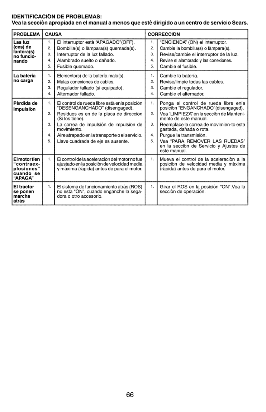
IDENTIFICACION
DE
PROBLEMAS:
Vea
la
seccion
apropiada
en
el
manual
a
menos
que
este
dirigido
a
un
centro
de
servicio
Sears.
PROBLEMA
|
CAUSA
CORRECCION
Las
luz
1.
|
El
interruptor
esta
‘“APAGADO”(OFF).
1.
|
“ENCIENDA’
(ON)
et
interruptor.
(ces)
de
2.
|
Bombilla(s)
o
lampara(s)
quemada(s).
2.
|
Cambie
la
bombilla(s)
o
lampara(s).
a
tera(s)
3.
|
Interruptor
de
la
luz
fallado.
3.
|
Revise/cambie
el
interruptor
de
la
luz.
nando
4.
|
Alambrado
suelto
o
dahado.
4.
|
Revise
el
alambrado
y
las
conexiones.
5.
|
Fusible
quemado.
5.
|
Cambie
el
fusible.
La
bateria
1.
|
Elemento(s)
de
la
bateria
malo(s).
1.
|
Cambie
la
bateria.
no
carga
2.
|
Malas
conexiones
de
cables.
2.
|
Revise/limpie
todas
las
cables.
3.
|
Regulador
fallado
(si
equipado).
3.
|
Cambie
el
regulador.
4.
|
Alternador
fallado.
4.
|
Cambie
el
alternador.
Perdida
de
1.
|
El
control
de
rueda
libre
esta
enlaposicion
|
1.
|
Ponga
el
control
de
rueda
libre
enla
i
ic
“DESENGANCHADO”
(disengaged).
posicion
“ENGANCHADO”
(disengaged).
impulsion
2.
|
Residuos
es
en
de
la
placa
de
direccion
|
2.
|
Vea
“LIMPIEZA’
en
la
seccion
de
Manteni-
(Si
tos
tiene).
mento
de
este
manual.
3.
|
La
correa
de
impulsion
de
impulsion
de
|
3.
|
Reemplace
la
correa
de
movimien-to
esta
movimiento.
gastada,
danada
o
rota.
4.
| Aire
atrapado
enlatransporte
oelservicio.
|
4.
|
Purgue
la
transmision.
5.
|
Liave
cuadrada
de
eje
es
ausente.
5.
|
Vea
“PARA
REMOVER
LAS
RUEDAS”
en
la
seccion
de
Servicio
y
Ajustes
de
este
manual.
Elmotortien
|
1.
|
Elcontroldelaaceleraciondelmotornofue
|
1.
|
Mueva
el
control
de
la
aceleracion
a
la
“contraex-
ajustado
en
la
posicion
de
velocidad
media
posicion
de
velocidad
media
y
maxima
plosiones”
y
maxima
(rapida)
antes
de
para
el
motor.
(rapida)
antes
de
para
el
motor.
cuando
se
“APAGA’”
El
tractor
1.
|
El
sistema
de
funcionamiento
atras
(ROS)
|
1.
|
Girar
el
ROS
en
la
posicion
"ON".Vea
la
se
ponen
no
esta
"ON",
cuando
enganche
la
sega-
seccion
de
operacion.
marcha
dora
o
otro
accesorio.
atras
66
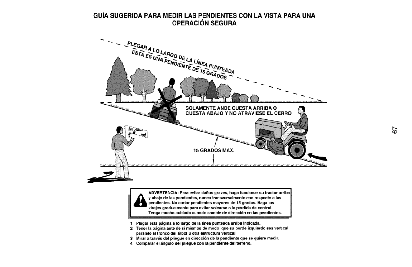
GUIA
SUGERIDA
PARA
MEDIR
LAS
PENDIENTES
CON
LA
VISTA
PARA
UNA
OPERACION
SEGURA
~"EGan
Esra
=
~
ARG
0
at
SOLAMENTE
ANDE
CUESTA
ARRIBA
O
CUESTA
ABAJO
Y
NO
ATRAVIESE
EL
CERRO
15
GRADOS
MAX.
CUO
UO
a
aaa
Sa
Oe
Aa
eno
a0)
Baa
aa
a
ae
aU
eo
aad
aa YY
aya
.
ADVERTENCIA:
Para
evitar
dafios
graves,
haga
funcionar
su
tractor
arriba
y
abajo
de
las
pendientes,
nunca
transversalmente
con
respecto
a
las
pendientes.
No
cortar
pendientes
mayores
de
15
grados.
Haga
los
virajes
graduaimente
para
evitar
volcarse
o
la
pérdida
de
control.
Tenga
mucho
cuidado
cuando
cambie
de
direccién
en
las
pendientes.
—
.
Plegar
esta
pagina
a
Jo
largo
de
la
linea
punteada
arriba
indicada.
2.
Tener
ta
pagina
ante
de
si
mismos
de
modo
que
su
borde
izquierdo
sea
vertical
paratelo
al
tronco
del
arbol
u
otra
estructura
vertical.
.
Mirar
a
través
del
pliegue
en
direccién
de
la
pendiente
que
se
quiere
medir.
.
Comparar
el
angulo
del
pliegue
con
la
pendiente
def
terreno.
pw
67

CRAFTSMAN
Product
questions
or
problems?
1-888-331-4569
Customer
Care
Hot
Line
Get
answers
to
questions,
troubleshoot
problems,
order
parts,
or
schedule
repair
service.
Para
respuestas
a
preguntas
o
problemas,
y
ordenar
piezas
o
pedir
servicio
para
la
reparacion
de
su
equipo.
To
help
us
help
you,
register
your
product
at
www.craftsman.com/registration
Para
poderte
ayudar
mejor,
registra
tu
producto
en
www.crafisman.com/registration
Join
the
Craftsman
Club
today!
CRAFTSMAN
Gay:
www.craftsman.com/signup
Receive
exclusive
member
benefits
including
special
pricing
and
offers,
project
sharing,
expert
advice,
and
SHOP
YOUR
WAY
REWARDS!
Como
miembro
exclusivo,
recibe
diversos
beneficios
como
ofertas,
precios
especiales,
proyectos
nuevos,
consejos
de
expertos
y
nuestro
programa
de
puntos
SHOP
YOUR
WAY
REWARDS!
®
Registered
Trademark
/
™
Trademark
of
KCD
IP,
LLC
in
the
United
States,
or
Sears
Brands,
LLC
in
other
countries
®
Marca
Registrada
/
™ Marca
de
Fabrica
de
KCD
IP,
LLC
en
Estados
Unidos,
o
Sears
Brands,
LLC
in
otros
paises
02.21.17 BD
Printed
in
the
U.S.A.


