Loading ...
Loading ...
Loading ...
13
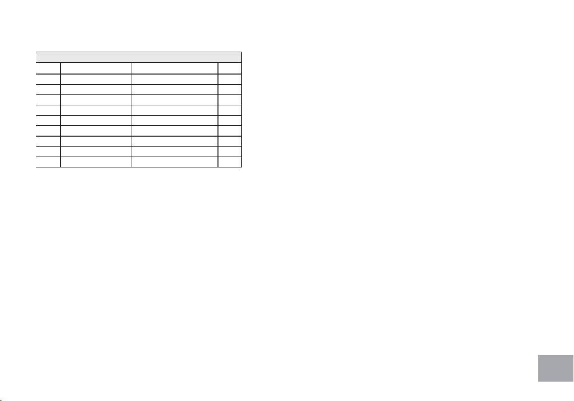
HARDWARE FOR STEP 1
PART TYPE DESCRIPTION QTY
103 BOLT
3/8”X3/4”
2
105 BOLT
3/8” X 2-1/4
1
116 PHILLIPS HEAD SCREW
M5 X 10mm
4
120 SHEET METAL SCREW
3.5 X16mm
3
130 NYLOC NUT
3/8” X 7T
2
137 FLAT WASHER
Ø3/8” × Ø19 × 1.5T
2
152 SPLIT WASHER
Ø10 × 2T
1
153 CURVED WASHER
Ø3/8” × 23 × 2T
6
176 BOLT
3/8” X 2-1/4”
6
1. Gather HARDWARE FOR STEP 1.
2. Locate the CONSOLE MAST (12) and CONSOLE MAST
COVER (72); slide the Cover onto the Mast as far as it will go.
Make sure the CONSOLE MAST COVER (72) is facing the
correct way.
3. At the top opening of the MAIN FRAME (1), there is a
COMPUTER CABLE (50) tied to a twist tie wire. Feed the
twist tie wire and COMPUTER CABLE (50) into the bottom
of the CONSOLE MAST (12) and out of the opening at the
top.
4. Install the CONSOLE MAST (12) into the receiving bracket
on the top of the MAIN FRAME (1). Be extremely careful
not to pinch the cables between the tubing. If the cable gets
pinched, this may affect the electrical functions of the console.
NOTE: There is one bolt already installed in the receiving
bracket that will engage with the slot at the bottom of the
Console Mast. This needs to be tightened last, after the three
other console mast bolts.
5. Place a SPLIT WASHER (152) onto the BOLT (105) and
hand tighten through the left side of the console mast. Place
a CURVED WASHER (153) onto each BOLT (103) and
thread both into the front of the console mast tube. Fasten
these front bolts as tight as possible with the WRENCH
(155). Next rmly tighten the two left side bolts with the same
wrench.
6. Connect the 2 HAND PULSE CABLES (48), RESISTANCE
CABLE (44), and COMPUTER CABLE (50) to the back of
the CONSOLE (43). Do not force the connectors; they will
only t one way and are different sizes to prevent confusion.
Store the excessive cable in the CONSOLE MAST TUBE
(12).
7. Attach the CONSOLE (43) to the bracket of the Console
Mast tube with 4 PHILLIPS HEAD SCREWS (116). Tighten
the screws with the PHILLIPS HEAD SCREW DRIVER
(157).
8. Attach the REAR FLOOR SUPPORT (15) to the RAILS
(2 & 3) with 2 Bolts (176) and Curved Washers (153) on
each side. Tighten using the COMBINATION M5 ALLEN
WRENCH & PHILLIPS HEAD SCREW DRIVER (177).
9. Slide the Rail Assembly into the MAIN FRAME (1). Insert 1
BOLT (176) through each side and attach a FLAT WASHER
(137) and a NYLOC NUT (130) to each joint on the inside.
Loading ...
Loading ...
Loading ...