
DDFCUC024
Fan Coil Unit
Controller
RJ12
211 mm (8.31 in)
95 mm (3.74 in)
75 mm (2.95 in)
1
45 mm
(1.77 in)
45 mm
(1.77 in)
Installation Instructions
Instructions d’installation
Installationsanweisungen
Instrucciones de instalación
Istruzioni per l’installazione
Installatie-instructies
インストール 手 順
安装指示
50° C (122° F)
0° C (32° F)
≤
90%
IEC Pollution Degree II
Devices must be installed in an
approved enclosure by a qualied
electrician in accordance with all
national and local electrical and
construction codes and regulations.
Les appareils doivent être installés dans un lieu jugé
apte, par un électricien qualié et conformément
aux règles et normes locales et nationales en
matière d’électricité et de construction.
Die Geräte müssen von einem geprüften Elektriker
entsprechend allen nationalen und lokalen Elektro
– und Bauvorschriften in einem zugelassenen
Gehäuse installiert werden.
Los dispositivos se deben instalar en un recinto
aprobado por un electricista cualicado de
acuerdo a todos los reglamentos eléctricos y de
construcción locales y nacionales pertinentes.
I dispositivi devono essere installati da un
elettricista qualicato in un luogo approvato, in
conformità a tutti gli standard e le norme nazionali
e locali vigenti in materia di impianti elettrici e
costruzioni edilizie.
Apparaten moeten door een erkende elektricien
worden geïnstalleerd in een goedgekeurde
behuizing in overeenstemming met alle nationale
en lokale elektriciteits – en bouwvoorschriften
en wetgeving.
デバイスを取り付ける際は、資格のある電気技師に依頼
し、電気と建設に関する国および地域のすべての法令に
従って、認可されている筐体内に取り付けてください。
根据国家/地区及当地的电气与建筑规范和法规,该设
备必须由有资质的电工安装在经批准的外罩内。
2
2
3
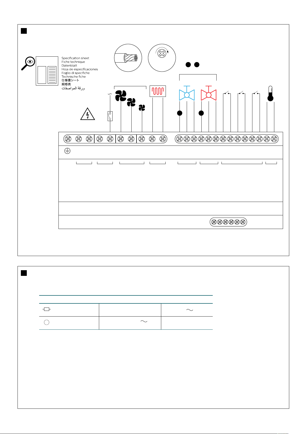
DDFCUC024
10 A
10 A 16 A 20 kΩ
A B
≤ 4 W+
A B
≤ 5 mm
2
10+ AWG
0.6 Nm
5.5 Lb-in
SHLD
GND
D+ D-
+12 V N/C
N N N L
FAN H
FAN M
FAN L
HEAT I
HEAT O
OPEN
CLOSE
COM
OPEN
CLOSE
COM
IN 1
0 V
IN 2
0 V
IN 3
0 V
TS
0 V
NEUTRAL
LINK
SUPPLY
IN
HEATER
SWITCH
FEED
THROUGH
COLD
VALVE
HOT
VALVE
DRY CONTACT
INPUTS
TEMP
SENSE
FAN OUT
Output Ratings / Channel
General Use
Load Type Fan Heater
Motor
M
16 A, 230 V
8 FLA (1 HP), 230 V
3
5
4
RS-485 DyNet
0 V IN/TS
< 20 m
NEUTRAL
LINK
SUPPLY
IN
TEMP
SENSE
HEATER
SWITCH
FEED
THROUGH
COLD
VALVE
HOT
VALVE
DRY CONTACT
INPUTS
FAN OUT
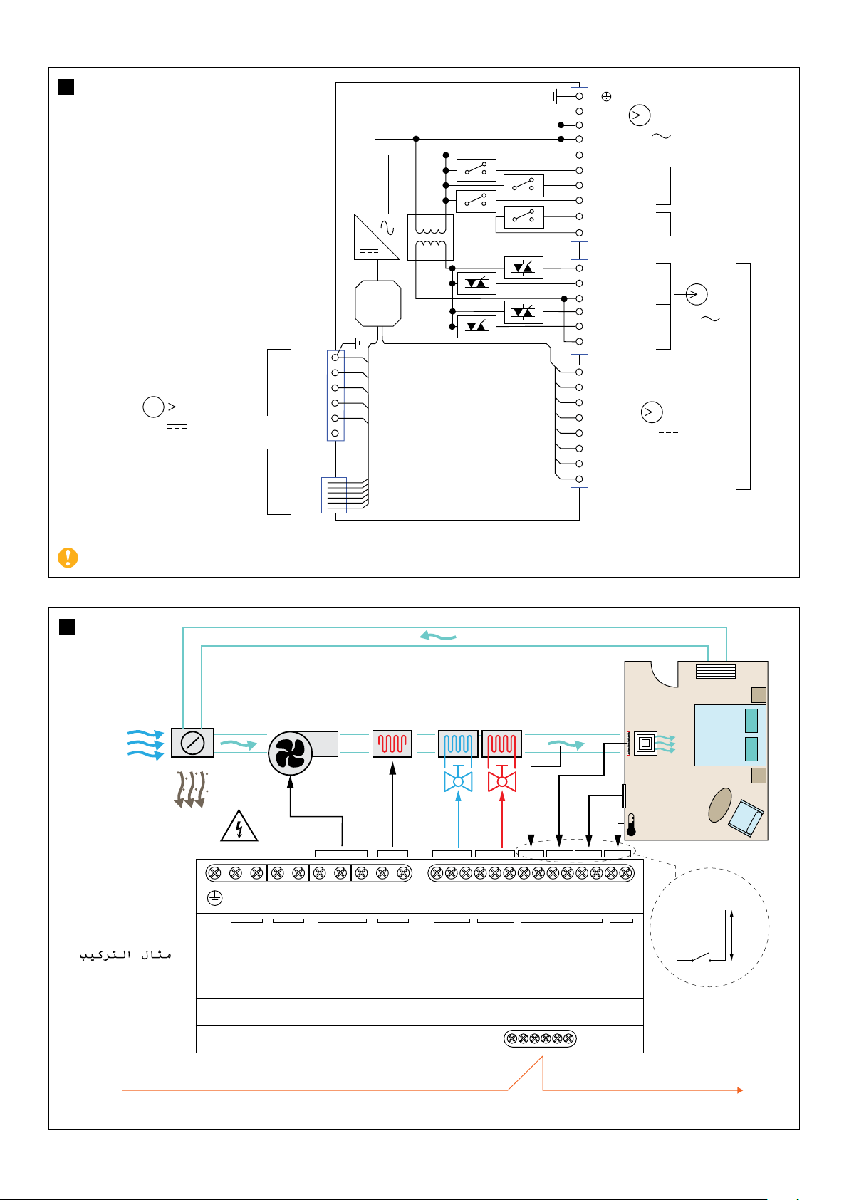
Installation example
Exemple d'installation
Installationsbeispiel
Ejemplo de instalación
Esempio di installazione
Installatievoorbeeld
設置例
安装示例
N N N L
FAN H
FAN M
FAN L
HEAT I
HEAT O
OPEN
CLOSE
COM
OPEN
CLOSE
COM
IN 1
0 V
IN 2
0 V
IN 3
0 V
TS
0 V
SHLD
GND
D+ D-
+12 V N/C
N
N
N
L
µP
FAN High
Heater In
24 VAC
0 V
TS
0 V
DC2
DC3
0 V
0 V
DC1
RS-485
DyNet
RJ12
+12 V
N/C
D +
D -
GND
SHLD
FAN Medium
MAX 16 A
MAX 10 A
FAN Low
Heater Out
OPEN
CLOSE
CLOSE
Common
OPEN
Common
HOT
SELV/Class 2 (UL)
COLD
230 V ± 14%
10 A
12 V 120 mA
SELV/Class 2 (UL)
≤ 5 V
1 mA
E
24 V 4 W
IEC Overvoltage Category III

7 8
RS-485 DyNet
This is a class A product. In a domestic environment this product may cause radio interference, in which case the user may be required to take adequate measures.
AZZ 410 1021 R18
© 2021 Signify Holding. All rights reserved. Specications are subject to
change without notice. No representation or warranty as to the accuracy or
completeness of the information included herein is given and any liability
for any action in reliance thereon is disclaimed. Philips and the Philips
Shield Emblem are registered trademarks of Koninklijke Philips N.V. All other
trademarks are owned by Signify Holding or their respective owners.
www.lighting.philips.com/dynalite
6 A 6 B
SHLD
GND
D+ D-
+12 V N/C
HEAT I
HEAT O
OPEN
CLOSE
COM
OPEN
CLOSE
COM
IN 1
0 V
IN 2
0 V
IN 3
0 V
TS
0 V
HEATER
SWITCH
FEED
THROUGH
COLD
VALVE
HOT
VALVE
DRY CONTACT
INPUTS
TEMP
SENSE
RS-485 DyNet
SHLD
GND
D+
D-
+12 V
N/C
≤ 2 A
0.3-2.5 mm
2
22-12 AWG
0.4 Nm
3.5 Lb-in
SHLD
GND
D+ D-
+12 V N/C
N N N L
FAN H
FAN M
FAN L
HEAT I
HEAT O
OPEN
CLOSE
COM
OPEN
CLOSE
COM
IN 1
0 V
IN 2
0 V
IN 3
0 V
TS
0 V
NEUTRAL
LINK
SUPPLY
IN
HEATER
SWITCH
FEED
THROUGH
COLD
VALVE
HOT
VALVE
DRY CONTACT
INPUTS
TEMP
SENSE
FAN OUT
RJ12
DyNet RS-485
RJ12
+12 V
+12 V
D-
D+
GND
GND
