Owner's Guide Car Accessories
On-Board Diagnostics (OBD) II
The first generation of On-Board Diagnostics (called OBD I) was developed by the California Air Resources Board (CARB) and implemented in 1988 to monitor some of the emission control components on vehicles. As technology evolved and the desire to improve the On-Board Diagnostic system increased, a new generation of On-Board Diagnostic system was developed. This second generation of On-Board Diagnostic regulations is called "OBD II".
The OBD II system is designed to monitor emission control systems and key engine components by performing either continuous or periodic tests of specific components and vehicle conditions. When a problem is detected, the OBD II system turns on a warning lamp (MIL) on the vehicle instrument panel to alert the driver typically by the phrase "Check Engine" or "Service Engine Soon". The system will also store important information about the detected malfunction so that a technician can accurately find and fix the problem. Here below follow three pieces of such valuable Information:
- Whether the Malfunction Indicator Light (MIL) is commanded 'on' or 'Off'
- Which, if any, Diagnostic Trouble Codes (DTCs) are stored;
- Readiness Monitor status.
Diagnostic Trouble Codes (DTCs)
OBD II Diagnostic Trouble Codes are codes that are stored by the on-board computer diagnostic system in response to a problem found in the vehicle. These codes identify a particular problem area and are intended to provide you with a guide as to where a fault might be occurring within a vehicle. OBD IIDiagnostic Trouble Codes consist of a five-digit alphanumeric code. The first character, a letter, identifies which control system sets the code. The other four characters, all numbers, provide additional information on where the DT Coriginated and the operating conditions that caused it to be set. Below is an example to illustrate the structure of the digits:
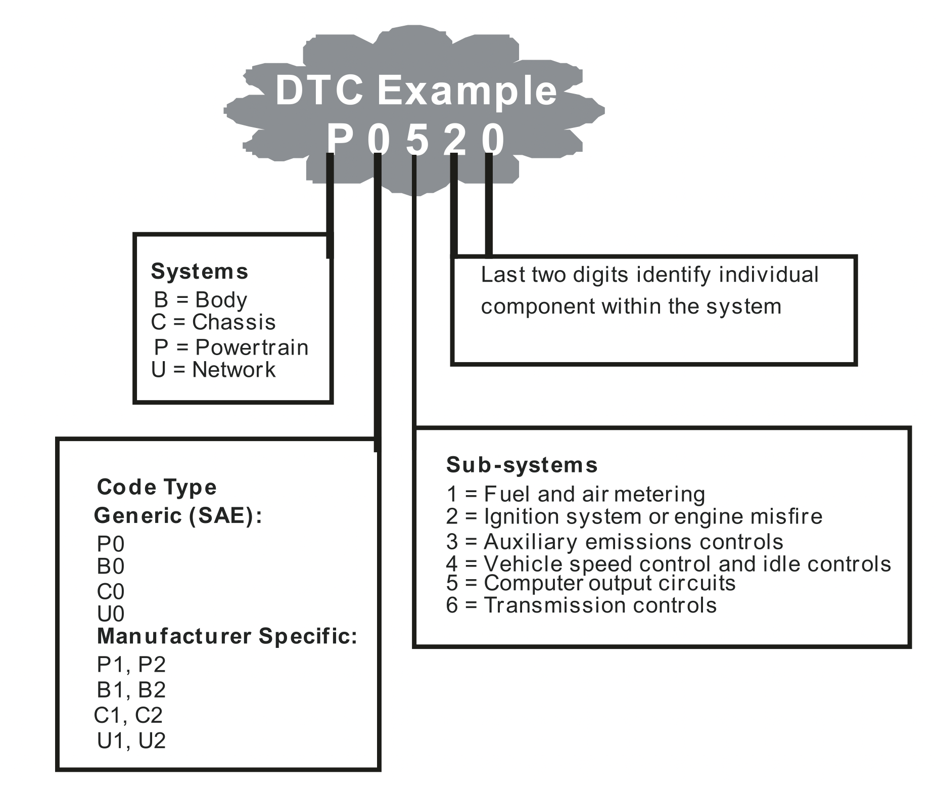
Figure 1-2: Explanation of a diagnostic trouble code.
Location of the Data Link Connector(DLC)
The DLC (Data Link Connector or Diagnostic Link Connector) is the standardized 16-cavity connector where diagnostic scan tools interface with the vehicle's on-board computer. The DLC is usually located 12 inches from the center of the instrument panel (dash), under or around the driver's side for most vehicles. If the Data Link Connector is not located under the dashboard, a label should be there revealing its location. For some Asian and European vehicles, the DLC is located behind the ashtray and the ashtray must be removed to access the connector. If the DLC cannot be found, refer to the vehicle's service manual for the location.

Figure 1-3: The DLC connector (left) can be found in the area of the car interior seen at right (black arrow).
OBD Il Readiness Monitors
Readiness Monitors are indicators used to find out if all of the emissions components have been evaluated by the OBD II system. They are running periodic tests on specific systems and components to ensure that they are performing within allowable limits.
Currently, there are eleven OBD II Readiness Monitors (or I/M Monitors) defined by the U.S. Environmental Protection Agency (EPA). Not all monitors are supported by all vehicles and the exact number of monitors in any vehicle depends on the motor vehicle manufacturer's emissions control strategy.
Comtinuous Monitors-Some of the vehicle components or systems are continuously tested by the vehicle's OBD II system, while others are tested only under specific vehicle operating conditions.The continuously monitored components listed below are always ready:
- Misfire
- Fuel System
- Comprehensive Components (CCM)
Once the vehicle is running, the OBD II system is continuously checking the above components, monitoring key engine sensors, watching for engine misfire, and monitoring fuel demands.
Non-Continuous Monitors-Unlike the continuous monitors, many emissions and engine system components require the vehicle to be operated under specific conditions before the monitor is ready. These monitors are termed non-continuous monitors and are listed below:
- EGR System - exhaust Gas Recirculation for reducing green house gases.
- O2 Sensors - monitor and adjust air/fuel mixture.
- Catalyst - reduces exhaust emissions.
- Evaporative System - monitors the integrity of the fuel tank system.
- O2 Sensor Heater - brings O2 sensor to correct operating temperature.
- Secondary air - reduces exhaust emissions.
- Heated Catalyst - brings catalyst to correct operating temperature.
- A/C system - monitors system for freon leaks.
OBD II Monitor Readiness Status
OBD II systems must indicate whether or not the vehicle's PCM's monitoring has completed testing on each emission component. Components that have been OBD II tested will be reported as "OK”. The purpose of recording readiness status is to allow inspectors to determine if the vehicle's OBD II system has tested all the emissions systems. This is handy to know before bringing vehicle to a state emissions testing facility.
The powertrain control module (PCM) sets a monitor to “OK” after an appropriate drive cycle has been performed. The drive cycle that enables a Monitor and sets readiness codes to “OK” varies for each individual monitor. Once a monitor is set as “OK”, it will remain in this state. A number of factors, including erasing of diagnostic trouble codes (DTCs) with a code reader or a disconnected battery, can result in Readiness Monitors being set to "INC" (incomplete). Since the three continuous monitors are constantly evaluating, they will be reported as “OK” all of the ime. As long as there are no DTCs stored in memory, the vehicle is running in accordance with the OBD II guidelines. If testing of a particular supportes non-continuous monitor has not been completed or not tested, the monitor status will be reported as "INC"(incomplete).
In order for the OBD monitor system to become ready, the vehicle should be driven under a variety of normal operating conditions. These operating conditions may include a mix of highway driving and stop and go, city type driving, and at least one overnight-off period. For specific information on getting your vehicle's OBD monitor system ready, please consult your vehicle owner's manual.
OBD II Definitions
Powertrain Control Module (PCM) - the OBD II terminology for the on-board computer that controls the engine and the drive train.
Malfunction Indicator Light (MIL) - Malfunction Indicator Light (Service Engine Soon, Check Engine) is a term used for the light on the instrument panel. It is to alert the driver and/or the repair technician that there is a problem with one or more of vehicle's systems and may cause emissions to exceed federal standards. If the MIL illuminates with a steady light, it indicates that a problem has been detected and the vehicle should be serviced as soon as possible. Under certain conditions, the dashboard light will blink or flash. This indicates a severe problem and flashing is intended to discourage vehicle operation. The vehicle onboard diagnostic system can not turn the MIL off until necessary repairs are completed or the condition no longer exists.
DTC-Diagnostic Trouble Codes (DTC) these identify which section of the emission control system has malfunctioned.
Enabling Criteria - Also termed Enabling Conditions. They are the vehicle-specific events of conditions that must occur within the engine before the various monitors will set, or run. Some monitors require the vehicle to follow a prescribed “drive cycle" routine as part of the enabling criteria. Drive cycles vary among vehicles and for each monitor in any particular vehicle.
OBD II Drive Cycle - A specific mode of vehicle operation that provides conditions required to set all the readiness monitors applicable to the vehicle to the “ready" condition. The purpose of completing an OBD II drive cycle is to force the vehicle to run its onboard diagnostics. Some form of a drive cycle needs to be performed after DTCs have been erased from the PCM's memory or after the battery has been disconnected. Running through a vehicle's complete drive cycle will “set” the readiness monitors so that future faults can be detected. Drive cycles vary depending on the vehicle and the monitor that needs to be reset. For vehicle specific drive cycle, consult the vehicle's Owner's Manual.
Freeze Frame Data-When an emissions related fault occurs, the OBD II system not only sets a code, but also records a snapshot of the vehicle operating parameters to help in identifying the problem. This set of values operating parameters to help in identifying the problem. This set of values is referred to as Freeze Frame Date and may include important engine is referred to as Freeze Frame Date and may include important engine parameters such as engine RPM, vehicle speed, air flow, engine load, fuel pressure, fuel trim value, engine coolant temperature, ignition timing advance, or closed loop status.
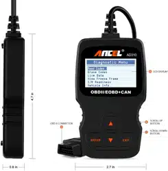
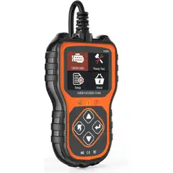
Tool Description - ANCEL AD310
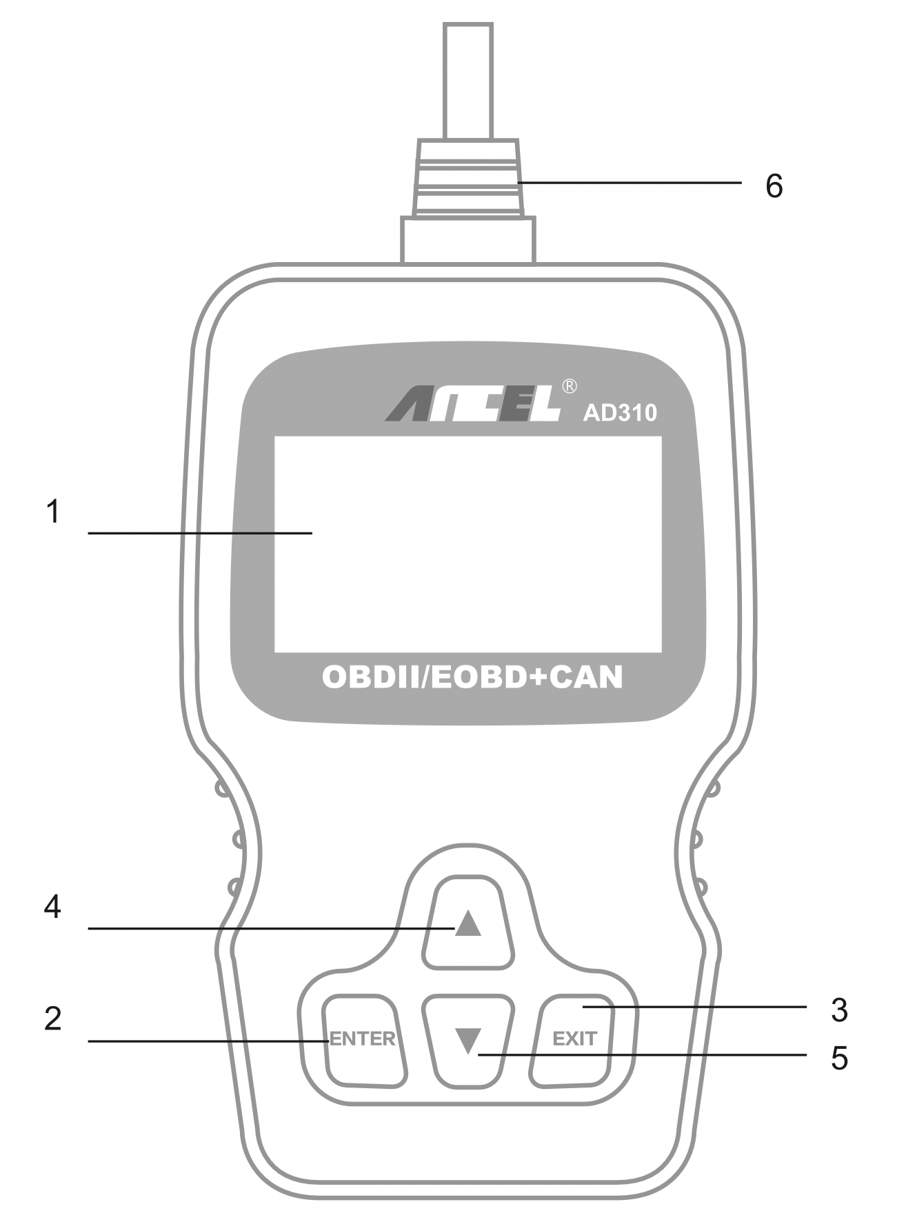
- LCD DISPLAY - Indicates test results. Backlit, 128 x 64 pixel display with contrast adjustment.
- ENTER BUTTON - Confirms a selection (or action) from a menu.
- EXIT BUTTON - Cancels a selection (or action) from a menu or returns to the menu. It is also used to exit DTC Lookup screen.
- UP SCROLL BUTTON - Moves up through menu and submenu items in menu mode. When more than one screen of data is retrieved, moves up through the current screen to the previous screens for additional data.
- DOWN SCROLL BUTTON - Moves down through menu and submenu items in menu mode. When more than one screen of data is retrieved, moves down through the current screen to next screens for additional data.
- OBD II CONNECTOR - Connects the scan tool to the vehicle's Data Link Connector (DLC).
Included
- AD310 Scan Tool main unit
- User's Manual
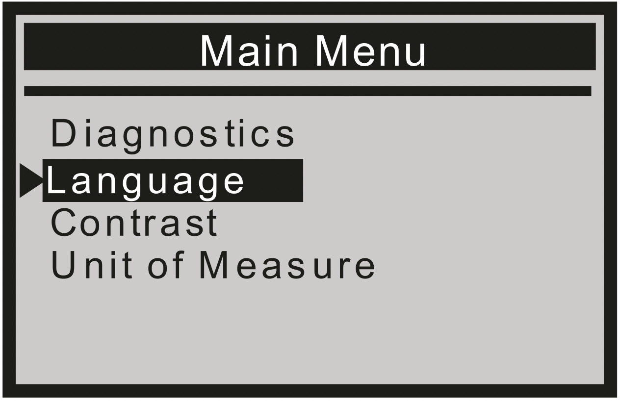
Language
- From the Main Menu, use the UP/DOWN scroll button to select the Language and press the ENTER button.
Contrast
- From the Main Menu, use the UP/DOWN scroll button to select Contrast, and press ENTER.
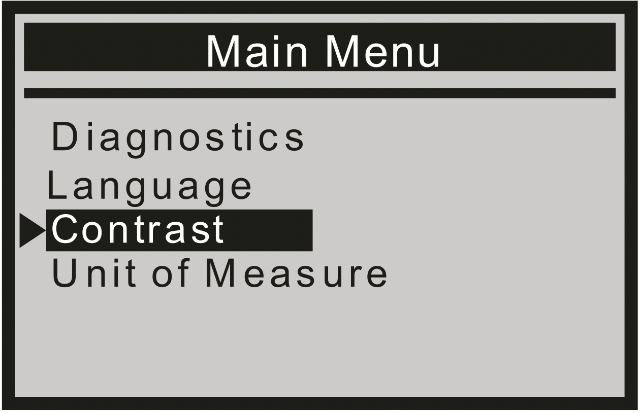
- From the Contrast menu, use the UP/DOWN scroll button to increase or decrease contrast.
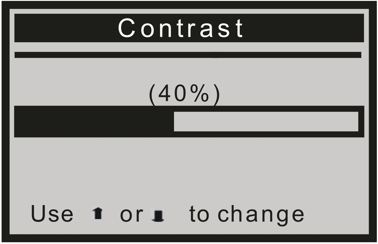
- Press ENTER to save your settings and return to the previous menu.
Unit of Measure
- From the Main Menu, use the UP/DOWN scroll button to select Unit of Measure, and press ENTER.
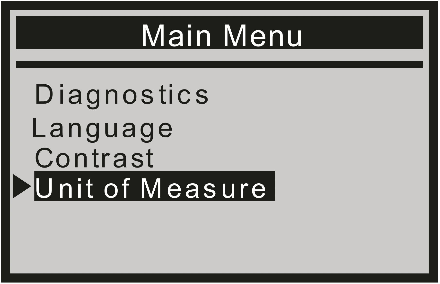
- From the Unit of Measure menu, use the UP/DOWN scroll button to select the desired Unit of Measure.
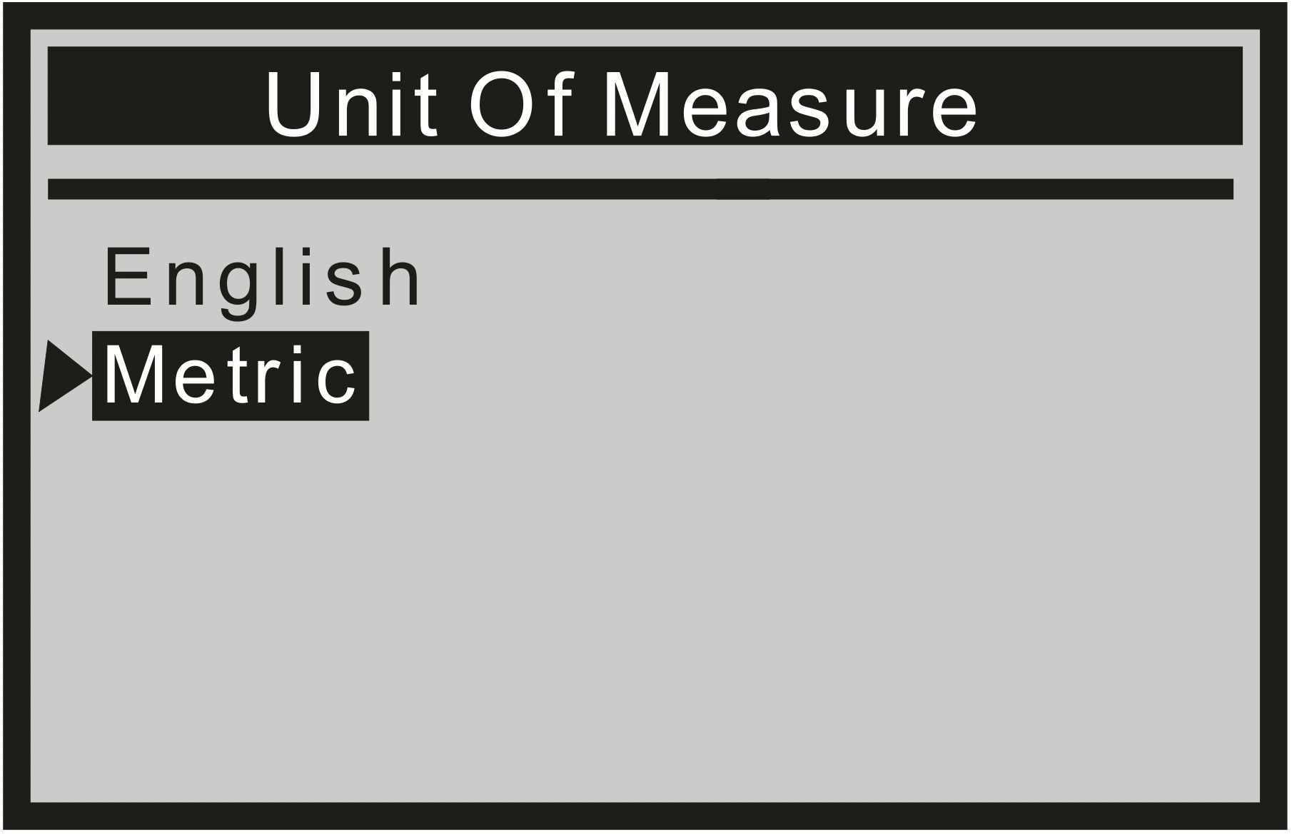
- Press the ENTER button to save your selection and return to the previous menu.
OBD II Diagnostics
CAUTION: Don't connect or disconnect any test equipment with ignition on or engine running.
- Turn the ignition off.
- Locate the vehicle's 16-pin Data Link Connector (DLC).
- Plug the scan tool cable connector into the vehicle's DLC.
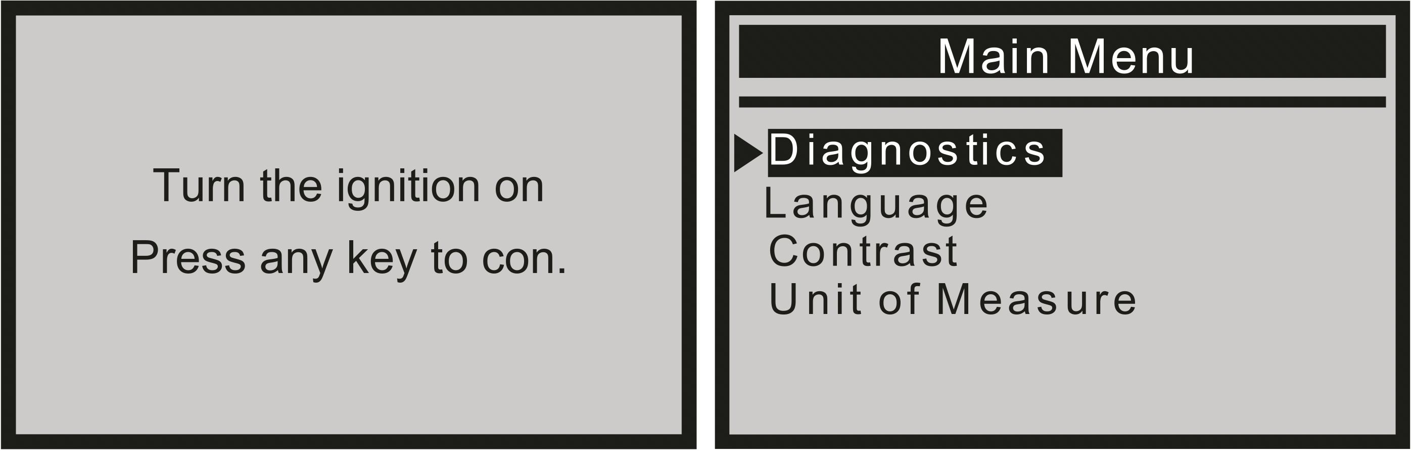
- Turn the ignition on.
- Press ENTER to enter Main Menu. Use the UP/DOWN scroll button to select Diagnostics from the menu.
- Press ENTER to confirm. A sequence of messages displaying the OBD II protocols will be observed on the display until the vehicle protocol is detected.
If the scan tool fails to communicate with the vehicle's ECU (Engine Control Unit), a "LINKING ERROR!" message shows up on the display.
- Verify that the ignition is ON;
- Check if the scan tool's OBD II connector is securely connected to the vehicle's DLC;
- Verify that the vehicle is OBD II compliant;
- Turn the ignition 'off' and wait for about 10 seconds. Turn the ignition back to 'on' and repeat the procedure from step 5.
Read Codes
- Stored codes are also known as "hard codes" or "permanent codes". These codes cause the control module to illuminate the malfunction indicator lamp (MIL) when an emission-related fault occurs.
- Pending Codes are also referred to as "maturing codes" or "continuous monitor codes". They indicate problems that the control module has detected during the current or last driving cycle, but are not considered serious, yet. Pending Codes will not turn on the malfunction indicator serious, yet. Pending Codes will not turn on the malfunction indicator up cycles, the code clears from memory.
- Use the UP/DOWN scroll button to select Read Codes from the Diagnostic Menu and press ENTER.
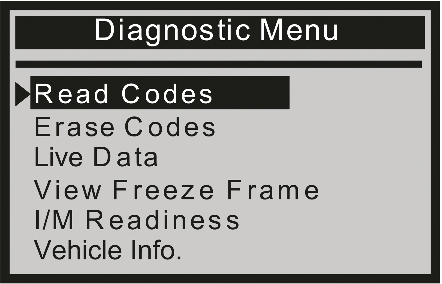
- Use the UP/DOWN scroll button to select Stored Codes or Pending Codes from the Trouble Codes menu and press ENTER.

If there are no Diagnostic Trouble Codes present, the display indicates "No (pending) codes are stored in the module!" Wait a few seconds or press any key to return to the Diagnostic Menu.
- View DTCs and their definitions on screen.
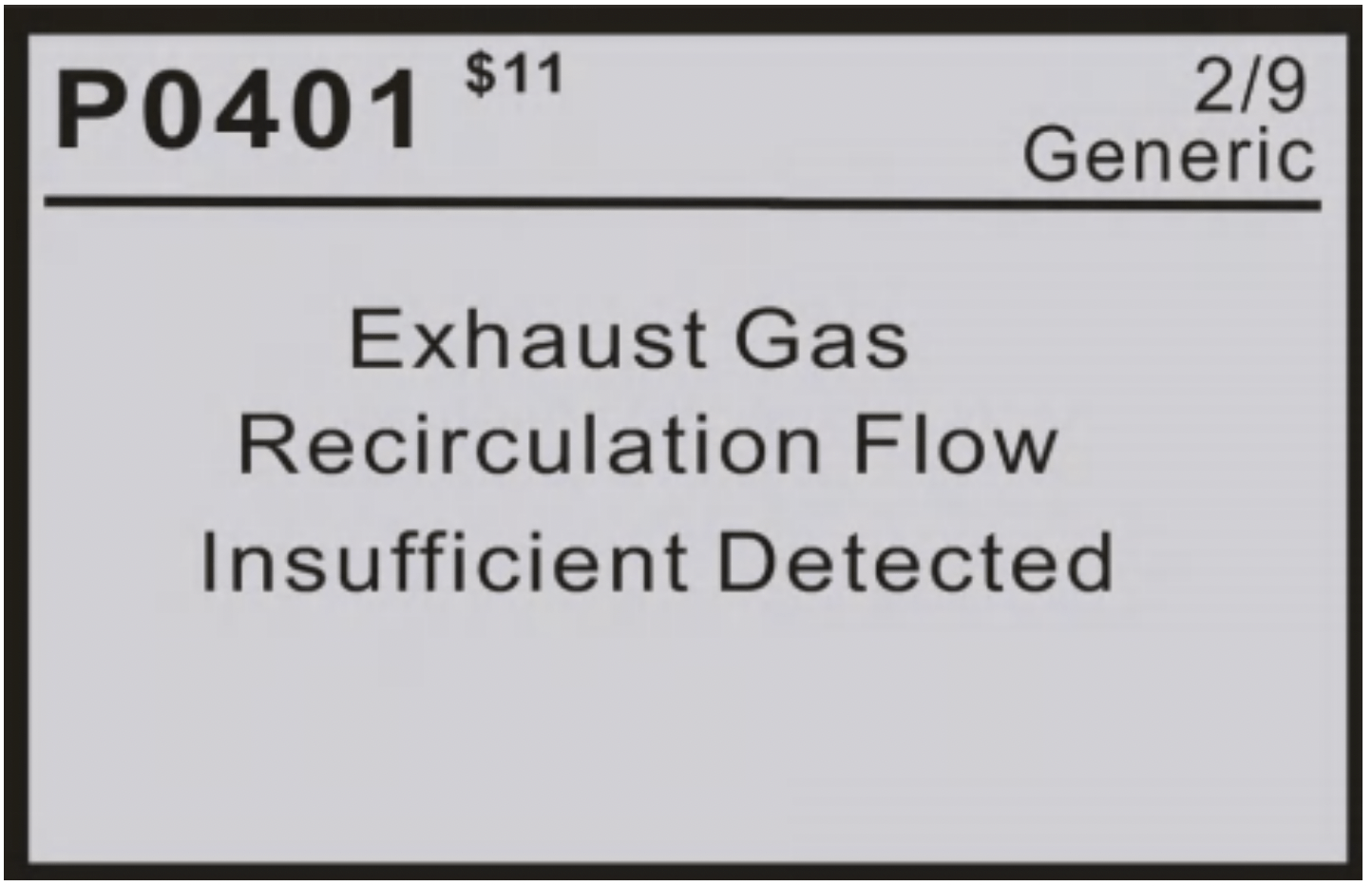
The control module number, sequence of the DTCs, total number of codes detected and type of codes (Generic of Manufacturer specific) will be observed on the upper right hand corner of the display.
- If more than one DTC is found, use the UP/DOWN scroll button, as necessary, until all the codes have been viewed.
If retrieved DTCs contain any manufacturer specific or enhanced codes, a "Manufacturer specific codes are found! Press any key to select vehicle make!" message comes up prompting you to select vehicle manufacturer to view DTC definitions. Use the UP/DOWN scroll button to select manufacturer and then press ENTER to confirm.
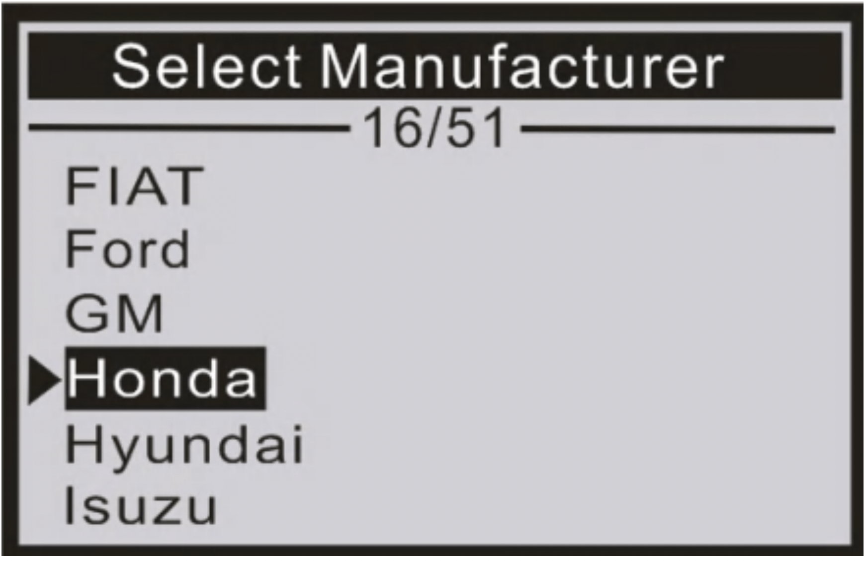
If the manufacturer for your vehicle is not listed, use the UP/DOWN scroll button to select "Other" and press ENTER.
Erase Codes
Notes:
- This function is performed with key on engine off. Do not start the engine.
- Before performing this function, make sure to retrieve and record the trouble codes.
- After clearing, you should retrieve trouble codes once more or turn ignition on and retrieve codes again. If there is still some trouble codes for hard troubles, please find the reason caused the trouble code firstly, and then solve the problem. Now, the trouble codes can be erased.
- Use the UP/DOWN scroll buttons to select Erase Codes from the Diagnostic Menu and press ENTER.
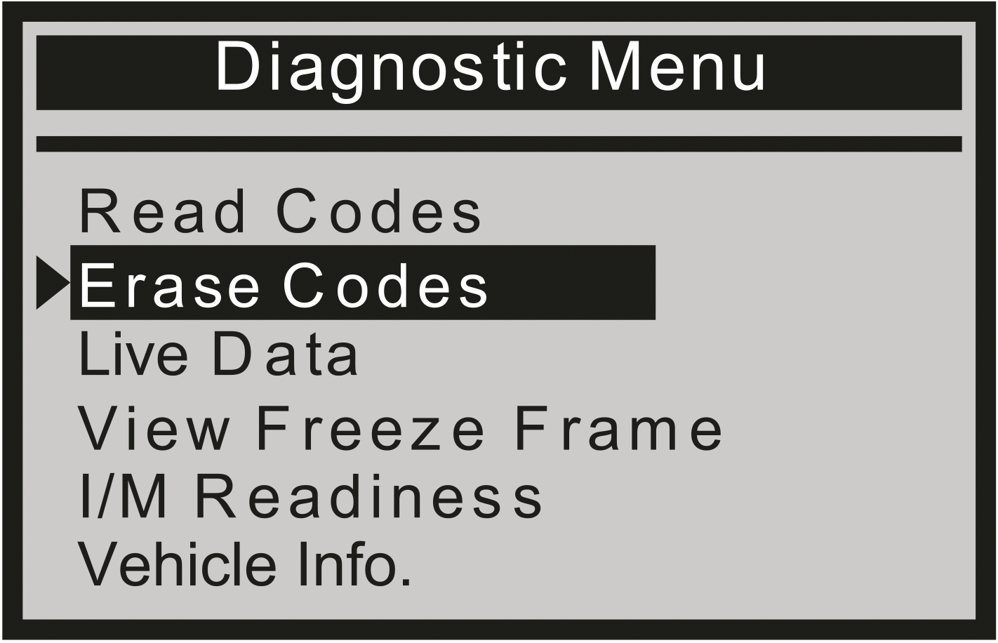
- A warning message comes up asking for your confirmation.
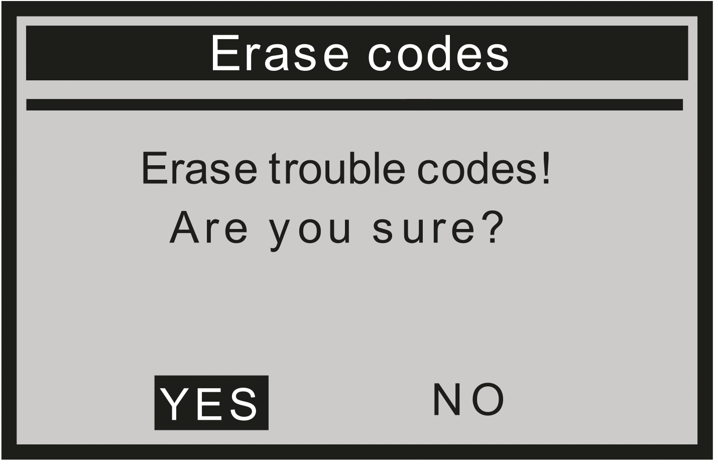
- Press ENTER to confirm
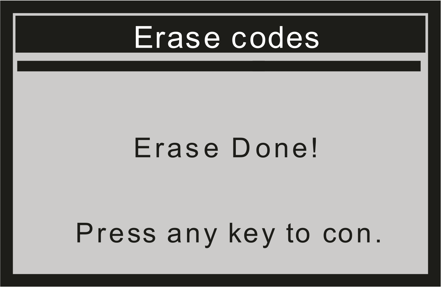
If the codes are cleared successfully, an "Erase Done!" confirmation message is displayed.
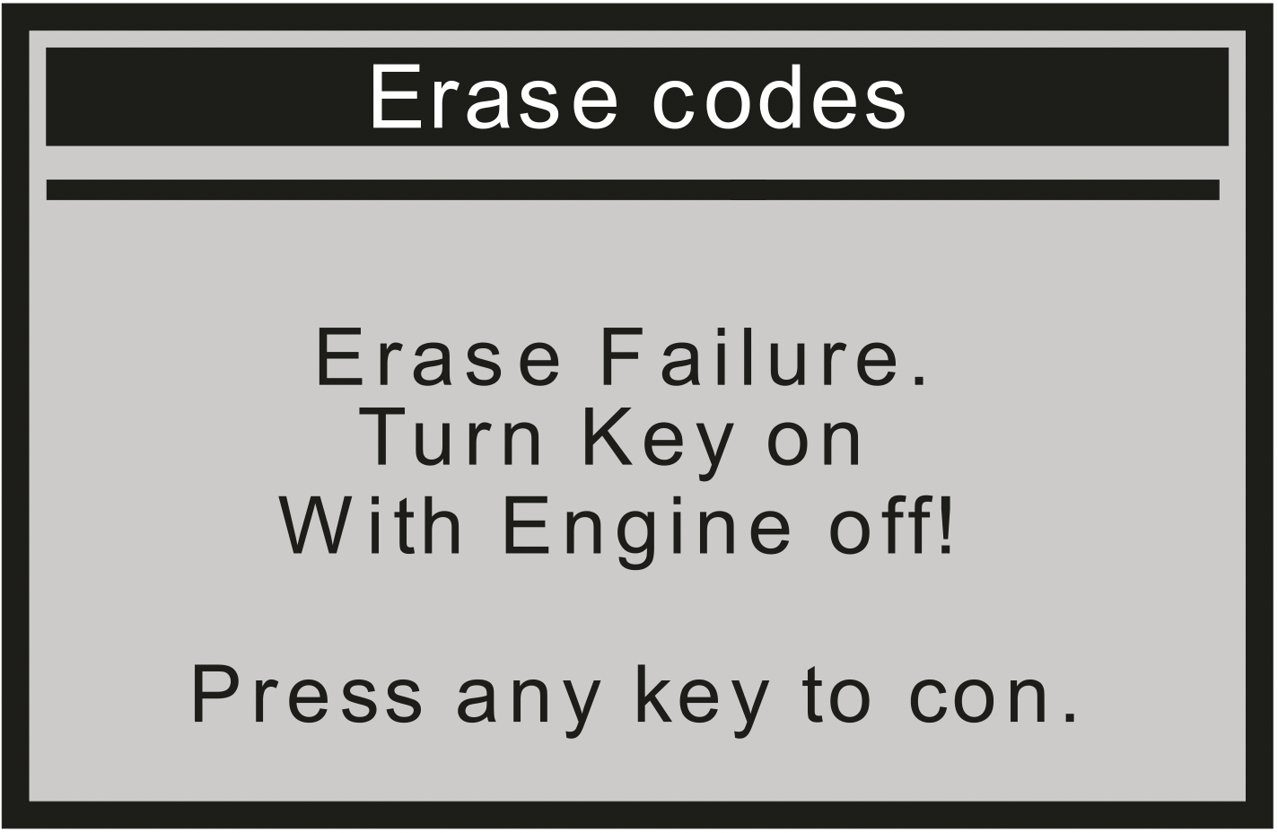
If the codes are not cleared, then an "Erase Failure. Turn Key on with Engine off!" message is displayed.