
For your safety, read carefully and keep in this vehicle.
2021 ALTIMA SEDAN
OWNER’S MANUAL
and MAINTENANCE INFORMATION
CALIFORNIA PROPOSITION 65 WARNING
WARNING
Operating, servicing and maintaining a passenger
vehicle or off-highway motor vehicle can expose you to
chemicals including engine exhaust, carbon monoxide,
phthalates, and lead, which are known to the State of
California to cause cancer and birth defects or other
reproduc tive harm. To minimize exposure, avoid
breathing exhaust, do not idle the engine except as
necessary, service your vehicle in a well-ventilated area
and wear gloves or wash your hands frequently when
servicing your vehicle. For more information go to
www.P65Warnings.ca.gov/passenger-vehicle.

This manual was prepared to help you un-
derstand the operation and maintenance
of your vehicle so that you may enjoy many
miles (kilometers) of driving pleasure.
Please read through this manual before
operating your vehicle.
A separate Warranty Information Book-
let explains details about the warranties
covering your vehicle. The “Maintenance
and schedules” section of this manual
explains details about maintaining and
servicing your vehicle. Additionally, a
separate Customer Care/Lemon Law
Booklet (U.S. only) will explain how to re-
solve any concerns you may have with
your vehicle, and clarify your rights un-
der your state's lemon law.
When you require any service or have any
questions, a NISSAN dealer will be glad to
assist you with the extensive resources
available to them.
In addition to factory-installed options,
your vehicle may also be equipped with
additional accessories installed prior to de-
livery. It is recommended that you visit a
NISSAN dealer for details concerning the
particular accessories with which your ve-
hicle is equipped. It is important that you
familiarize yourself with all disclosures,
warnings, cautions and instructions con-
cerning proper use of such accessories
prior to operating the vehicle and/or ac-
cessory. It is recommended that you visit a
NISSAN dealer for details concerning the
particular accessories with which your ve-
hicle is equipped.
Before driving your vehicle, please read this
Owner's Manual carefully. This will ensure
familiarity with controls and maintenance
requirements assisting you in the safe op-
eration of your vehicle.
WARNING
IMPORTANT SAFETY INFORMATION
REMINDERS!
Follow these important driving rules to
help ensure a safe and comfortable trip
for you and your passengers!
• NEVER drive under the influence of
alcohol or drugs.
•
ALWAYS observe posted speed limits
and never drive too fast for conditions.
• ALWAYS give your full attention to
driving and avoid using vehicle fea-
tures or taking other actions that
could distract you.
• ALWAYS use your seat belts and ap-
propriate child restraint systems.
Preteen children should be seated in
the rear seat.
• ALWAYS provide information about
the proper use of vehicle safety fea-
tures to all occupants of the vehicle.
• ALWAYS review this Owner’s Manual
for important safety information.
FOREWORD READ FIRST—THEN DRIVE SAFELY
MODIFICATION OF YOUR VEHICLE
This vehicle should not be modified.
Modification could affect its perfor-
mance, safety, emissions or durability
and may even violate governmental
regulations. In addition, damage or per-
formance problems resulting from
modifications may not be covered un-
der NISSAN warranties.
WARNING
Installing an aftermarket On-Board Di-
agnostic (OBD) plug-in device that uses
the port during normal driving, for ex-
ample remote insurance company
monitoring, remote vehicle diagnos-
tics, telematics or engine reprogram-
ming, may cause interference or dam-
age to vehicle systems. We do not
recommend or endorse the use of any
aftermarket OBD plug-in devices, un-
less specifically approved by NISSAN.
The vehicle warranty may not cover
damage caused by any aftermarket
plug-in device.
This manual includes information for all
features and equipment available on this
model. Features and equipment in your ve-
hicle may vary depending on model, trim
level, options selected, order, date of pro-
duction, region or availability. Therefore,
you may find information about features or
equipment that are not included or in-
stalled on your vehicle.
All information, specifications and illustra-
tions in this manual are those in effect at
the time of printing. NISSAN reserves the
right to change specifications, perfor-
mance, design or component suppliers
without notice and without obligation.
From time to time, NISSAN may update or
revise this manual to provide Owners with
the most accurate information currently
available. Please carefully read and retain
with this manual all revision updates sent
to you by NISSAN to ensure you have ac-
cess to accurate and up-to-date informa-
tion regarding your vehicle. Current ver-
sions of vehicle Owner's Manuals and any
updates can also be found in the Owner
section of the NISSAN website at https://
owners.nissanusa.com/nowners/
navigation/manualsGuide. If you have
questions concerning any information in
your Owner's Manual, contact NISSAN Con-
sumer Affairs. For contact information, re-
fer to the NISSAN CUSTOMER CARE PRO-
GRAM page in this Owner’s Manual.
IMPORTANT INFORMATION ABOUT
THIS MANUAL
You will see various symbols in this manual.
They are used in the following ways:
WARNING
This is used to indicate the presence of
a hazard that could cause death or se-
rious personal injury. To avoid or re-
duce the risk, the procedures must be
followed precisely.
CAUTION
This is used to indicate the presence of
a hazard that could cause minor or
moderate personal injury or damage to
your vehicle. To avoid or reduce the risk,
the procedures must be followed
car efully.
WHEN READING THE MANUAL

If you see this symbol, it means “Do not do
this” or “Do not let this happen.”
If you see a symbol similar to these in an
illustration,it means the arrow points to the
front of the vehicle.
Arrows in an illustration that are similar to
these indicate movement or action.
Arrows in an illustration that are similar to
these call attention to an item in the
illustration.
CALIFORNIA PERCHLORATE
ADVISORY
Some vehicle parts, such as lithium bat-
teries, may contain perchlorate material.
The following advisory is provided: “Per-
chlorate Material – special handling may
apply. For additional information, refer
to www.dtsc.ca.gov/hazardouswaste/
perchlorate/”.
SiriusXM® services
require a subscription
after trial period and
are sold separately or
as a package. The
satellite service is
available only in the
48 contiguous USA
and DC. SiriusXM®
satellite service is also
available in Canada;
see www.siriusxm.ca.
© 2021 NISSAN NORTH AMERICA, INC.
All rights reserved. No part of this Owner's
Manual may be reproduced or stored in a
retrieval system, or transmitted in any
form, or by any means, electronic, me-
chanical, photocopying, recording or oth-
erwise, without the prior written permis-
sion of Nissan North America, Inc.
APD1005

NISSAN CARES . . .
Both NISSAN and your NISSAN dealer are dedicated to serving all your automotive needs. Your satisfaction with your vehicle and your
NISSAN dealer are our primary concerns. Your NISSAN dealer is always available to assist you with all your automobile sales and service
needs.
However, if there is something that your
NISSAN dealer cannot assist you with or
you would like to provide NISSAN directly
with comments or questions, please con-
tact the NISSAN Consumer Affairs Depart-
ment using our toll-free number:
For U.S. customers
1-800-NISSAN-1
(1-800-647-7261)
For Canadian customers
1-800-387-0122
The Consumer Affairs Department will ask
for the following information:
– Your name, address, and telephone
number
– Vehicle identification number (attached
to the top of the instrument panel on the
driver's side)
– Date of purchase
– Current odometer reading
– Your NISSAN dealer's name
– Your comments or questions
OR
You can write to NISSAN with the informa-
tion at:
For U.S. customers
Nissan North America, Inc.
Consumer Affairs Department
P.O. Box 685003
Franklin, TN 37068-5003
or via e-mail at:
nnaconsumer[email protected]om
For Canadian customers
Nissan Canada Inc.
5290 Orbitor Drive
Mississauga, Ontario L4W 4Z5
or via e-mail at:
information.c[email protected]om
If you prefer, visit us at:
www.nissanusa.com (for U.S. customers)
or
www.nissan.ca (for Canadian customers)
We appreciate your interest in NISSAN and thank you for buying a quality NISSAN vehicle.
NISSAN CUSTOMER CARE PROGRAM

Table of
contents
Illustrated table of contents
Safety-Seats, seat belts and supplemental restraint system
Instruments and controls
Pre-driving checks and adjustments
Monitor, climate, audio, phone and voice recognition systems
Starting and driving
In case of emergency
Appearance and care
Do-it-yourself
Maintenance and schedules
Technical and consumer information
Index
0
1
2
3
4
5
6
7
8
9
10
11


0 Illustrated table of contents
Air bags, seat belts and child restraints ..........0-2
Ex terior front ....................................0-3
Ex terior rear .....................................0-4
Passenger compartment .......................0-5
Instrument panel................................0-6
Engine compartment check locations...........0-8
Warning/Indicator lights........................0-10

1. Top tether strap anchor (P. 1-23)
2. Rear seat belts with pretensioner(s) for
outboard seating (P. 1-12)
3. Roof-mounted curtain side-impact and
rollover supplemental air bag (P. 1-46)
4. Front seat-mounted side-impact
supplemental air bag (P. 1-46)
5. Head restraints/headrests (P. 1-7)
6. Front seat belt with pretensioner(s) and
shoulder height adjuster (P. 1-12, 1-46)
7. Side-impact pressure sensor (driver's
side shown; passenger's side similar)
(P. 1-46)
8. Supplemental air bags (P. 1-46)
9. Front seats (P. 1-2)
10. Occupant classification sensor
(weight sensor) (P. 1-46)
11. Rear seats (P. 1-2)
12. LATCH (Lower Anchors and Tethers for
CHildren) system (P. 1-23)
13. Rear outboard seat-mounted side
impact supplemental air bag (P. 1-46)
Refer to the page number indicated in
parentheses for operating details.
LII2583
AIR BAGS, SEAT BELTS AND CHILD
RESTRAINTS
0-2 Illustrated table of contents

1. Power windows (P. 2-72)
2. Windshield (P. 8-19)
3. Wiper and washer switch (P. 2-53)
4. Engine hood (P. 3-22)
5. Front view camera (if so equipped)
(P. 4-15)
Radar sensor (P. 5-111 or 5-123)
6. Fog light switch (if so equipped) (P. 2-55)
Turn signal switch (P. 2-55)
7. Headlight switch (P. 2-55)
LED Daytime Running Lights (DRL)
system (if so equipped) (P. 2-55)
Replacing bulbs (P. 8-25)
8. Tire pressure (P. 8-29)
Flat tire (P. 6-3)
Tire chains (P. 8-29)
9. Mirrors (P. 3-29)
Side view camera (if so equipped)
(P. 4-15)
10. Door locks (P. 3-4)
NISSAN Intelligent Key® (P. 3-7)
Keys (P. 3-2)
Refer to the page number indicated in
parentheses for operating details.
LII2559
EXTERIOR FRONT
Illustrated table of contents 0-3

1. Rear window and outside mirror (if so
equipped) defroster switch (P. 2-54)
2. Trunk lid (P. 3-22)
3. Sonar sensors (if so equipped) (P. 5-154)
4. Rearview camera (P. 4-8)
5. Replacing bulbs (P. 8-25)
6. Fuel-filler cap (P. 3-25)
Fuel recommendation (P. 10-2)
Fuel-filler door (P. 3-25)
7. Child safety rear door lock (P. 3-7)
Refer to the page number indicated in
parentheses for operating details.
LIC4027
EXTERIOR REAR
0-4 Illustrated table of contents

1. Power moonroof (if so equipped)
(P. 2-75)
2. Sun visors (P. 3-28)
3. Interior lights (P. 2-76)
4. HomeLink® Universal Transceiver
(if so equipped) (P. 2-78)
Rearview mirror (P. 3-29)
5. Glove box (P. 2-69)
6. Cup holders (P. 2-69)
Console box (P. 2-69)
7. Rear armrest (P. 1-2)
Cup holders (P. 2-69)
Refer to the page number indicated in
parentheses for operating details.
LII2563
PASSENGER COMPARTMENT
Illustrated table of contents 0-5

1. Vents (P. 4-30)
2. Steering wheel switches for audio
control*
Vehicle information display controls
(P. 2-18, 2-33)
3. Headlight/fog light (if so equipped)/
turn signal switch (P. 2-55)
Paddle shifters (if so equipped) (P. 5-18)
4. Driver supplemental air bag (P. 1-46)
Horn (P. 2-62)
5. Meters and gauges (P. 2-4)
Warning and indicator lights (P. 2-9)
Vehicle information display (P. 2-18,
2-33)
6. Wiper and washer switch (P. 2-53)
7. Heater and air conditioner (P. 4-32, 4-39)
Heated seat switches (if so equipped)
(P. 2-62)
Heated steering wheel switch
(if so equipped) (P. 2-63)
8. Navigation system* (if so equipped)
Audio system*
9. Front passenger supplemental air bag
(P. 1-46)
10. Front passenger supplemental knee
airbag (P. 1-46)
11.. Glove box (P. 2-69)
12. Front passenger air bag status light
(P. 1-46)
Hazard warning flasher switch (P. 6-2)
13. Power outlet (P. 2-67)
USB connection por t (if so equipped)
(P. 4-2, 4-66)
Aux jack*
14. Cup holders (P. 2-69)
15 Shift lever (P. 5-18)
LII2584
INSTRUMENT PANEL
0-6 Illustrated table of contents

16. Electronic parking brake switch
(if so equipped) (P. 5-24)
Automatic brake hold switch
(if so equipped) (P. 5-27)
17. Push-button ignition switch (P. 5-13)
18. Cruise control switches (if so equipped)
(P. 5-68)
Bluetooth® Hands-free Phone System*
ProPILOT Assist Switch (if so equipped)
(P. 5-70)
19. Driver supplemental knee airbag
(P. 1-46)
20. Hood release (P. 3-22)
Fuel-filler door release (P. 3-25)
Tilt/telescopic steering wheel controls
(P. 3-27)
21. Trip computer reset switch (P. 2-4)
Instrument brightness control (P. 2-55)
Steering assist switch (for vehicles with
ProPILOT Assist) (if so equipped)
(P. 2-64)
Trunk opener (P. 3-22)
*: For additional information, refer to the
separate NissanConnect® Owner's Manual.
Refer to the page number indicated in
parentheses for operating details.
Illustrated table of contents 0-7

2.0L 4 cylinder (KR20DDET engine
model)
1. Engine coolant reservoir (P. 8-5)
2. Drive belt location (P. 8-16)
3. Engine oil filler cap (P. 8-7)
4. Brake fluid reservoir (P. 8-12)
5. Battery (P. 8-14)
6. Fuse/Fusible link box (P. 8-21)
7. Air cleaner (P. 8-18)
8. Radiator cap (P. 8-5)
9. Engine oil dipstick (P. 8-7)
10. Windshield-washer fluid reservoir
(P. 8-13)
Refer to the page number indicated in
parentheses for operating details.
LDI3260
ENGINE COMPARTMENT CHECK
LOCATIONS
0-8 Illustrated table of contents

2.5L 4 cylinder (PR25DD engine model)
1. Engine coolant reservoir (P. 8-5)
2. Drive belt location (P. 8-16)
3. Engine oil filler cap (P. 8-7)
4. Engine oil dipstick (P. 8-7)
5. Brake fluid reservoir (P. 8-12)
6. Battery (P. 8-14)
7. Fuse/Fusible link box (P. 8-21)
8. Air cleaner (P. 8-18)
9. Radiator cap (P. 8-5)
10. Windshield-washer fluid reservoir
(P. 8-13)
Refer to the page number indicated in
parentheses for operating details.
LDI3615
Illustrated table of contents 0-9
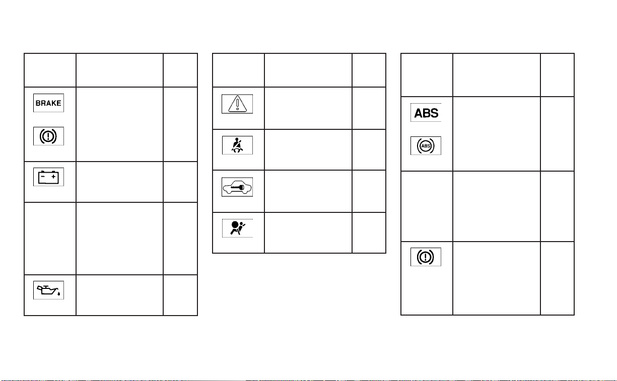
Warning/
Indicator
light (red)
Name Page
or
Brake warning
light
2-10
Charge warning
light
2-11
or
Electronic parking
brake indicator
light (if so
equipped)
2-11
Engine oil pres-
sure warning light
2-11
Warning/
Indicator
light (red)
Name Page
Master warning
light
2-12
Seat belt warning
light and chime
2-12
Security indicator
light
2-12
Supplemental air
bag warning light
2-12
Warning/
Indicator
light
(yellow)
Name Page
or
Anti-lock Braking
System (ABS)
warning light
2-13
Automatic Emer-
gency Braking
(AEB) with Pedes-
trian Detection
system warning
light
2-13
or
Electronic parking
brake warning
light (if so
equipped)
2-13
WARNING/INDICATOR LIGHTS
0-10 Illustrated table of contents
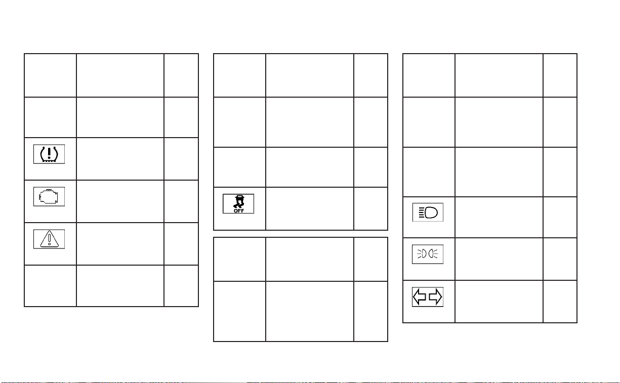
Warning/
Indicator
light
(yellow)
Name Page
Front passenger
air bag status
light
2-13
Low tire pressure
warning light
2-13
Malfunction Indi-
cator Light (MIL)
2-15
Master warning
light
2-16
Power steering
warning light
2-16
Warning/
Indicator
light
(yellow)
Name Page
Rear Automatic
Braking (RAB)
warning light (if so
equipped)
2-16
Slip indicator light 2-17
Vehicle Dynamic
Control (VDC) OFF
indicator light
2-17
Warning/
Indicator
light
(other)
Name Page
Automatic brake
hold indicator
light (white/
green) (if so
equipped)
2-17
Warning/
Indicator
light
(other)
Name Page
Front fog light
indicator light
(green) (if so
equipped)
2-17
High Beam Assist
indicator light
(green) (if so
equipped)
2-17
High beam indi-
cator light (blue)
2-18
Side light and
headlight indica-
tor light (green)
2-18
Turn signal/
hazard indicator
lights (green)
2-18
Illustrated table of contents 0-11

0-12 Illustrated table of contents

1 Safety-Seats, seat belts and
supplemental restraint system
Seats............................................ 1-2
Front manual seat adjustment
(if so equipped for passenger’s seat) ..........1-3
Front power seat adjustment
(for driver’s seat and if so equipped for
passenger’s seat) ............................ 1-4
Folding rear seat ............................. 1-5
Center armrest ................................1-7
Head restraints/headrests .......................1-7
Adjustable head restraint/headrest
components ................................. 1-8
Non-adjustable head restraint/
headrest components ....................... 1-9
Remove......................................1-9
Install ........................................1-10
Adjust ........................................1-10
Seatbelts.......................................1-12
Precautions on seat belt usage...............1-12
Seat belt warning light and chime ............1-14
Pregnant women ............................1-15
Injured persons ..............................1-15
Three-point type seat belt with
retractor .....................................1-15
Seat belt extenders .........................1-20
Seat belt maintenance ......................1-20
Child safety .....................................1-21
Infants .......................................1-21
Small children ...............................1-22
Larger children ..............................1-22
Child restraints .................................1-23
Precautions on child restraints ..............1-23
LATCH (Lower Anchors and Tethers for
CHildren) system ............................1-25
Rear-facing child restraint installation
using LATCH ................................1-29
Rear-facing child restraint installation
using the seat belts ..........................1-31
Forward-facing child restraint
installation using LATCH .....................1-34
Forward-facing child restraint
installation using the seat belts .............1-38
Booster seats ...............................1-42
Supplemental Restraint System (SRS) ..........1-46
Precautions on SRS .........................1-46
Supplemental air bag warning labels ........1-67
Supplemental air bag warning light .........1-67
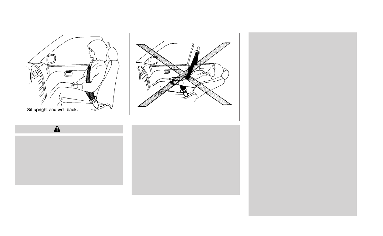
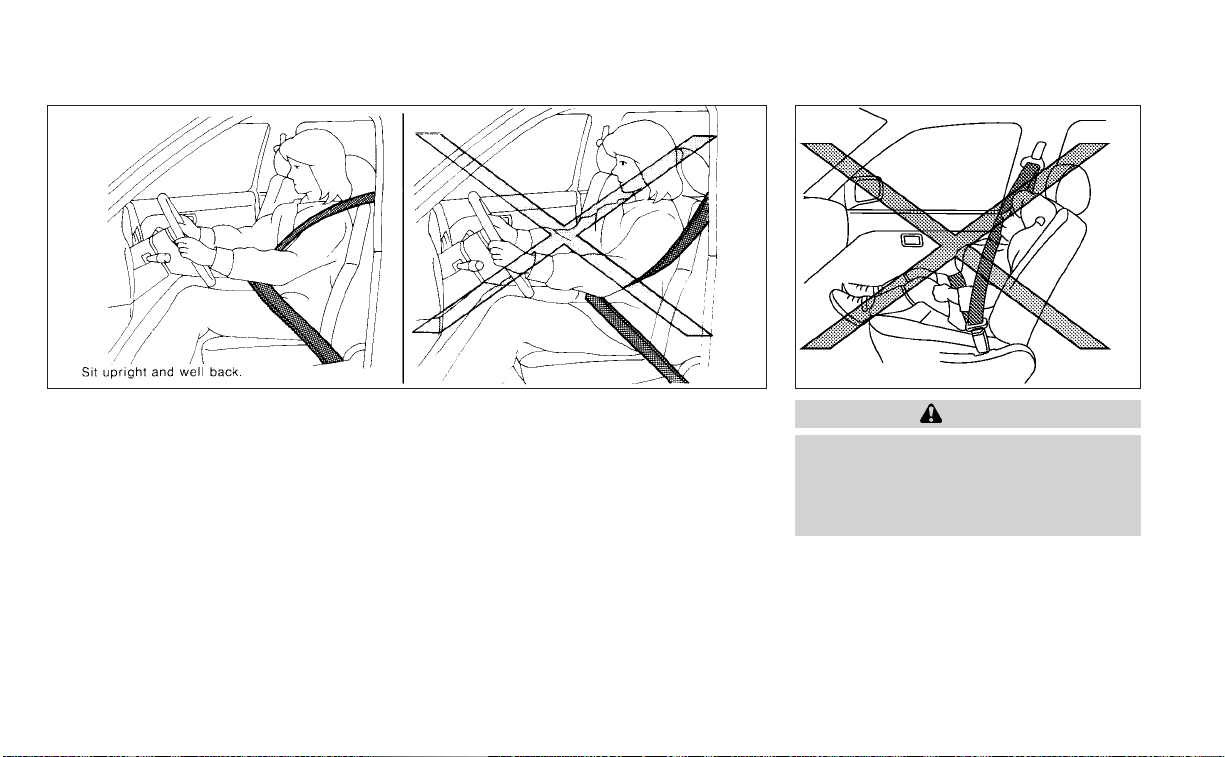
WARNING
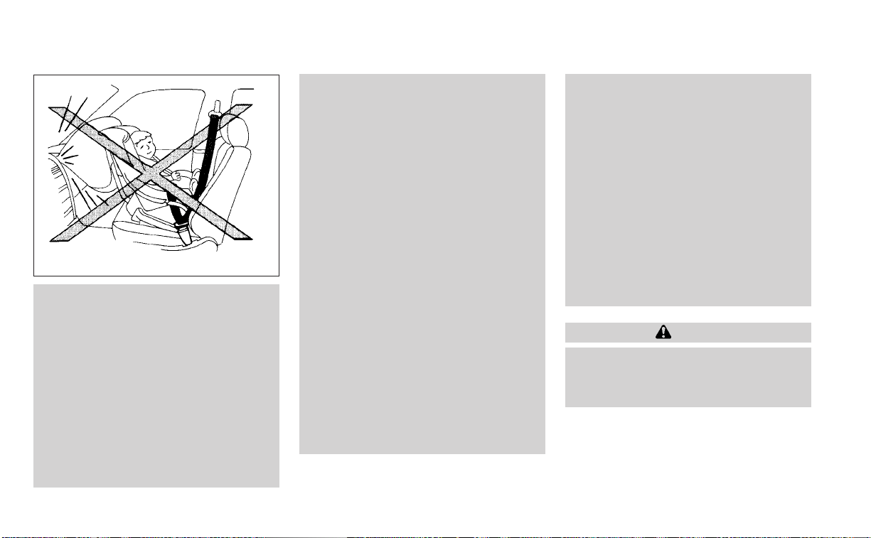
• Do not ride in a moving vehicle when
the seatback is reclined. This can be
dangerous. The shoulder belt will not
be against your body. In an accident,
you could be thrown into it and re-
ceive neck or other serious injuries.
You could also slide under the lap belt
and receive serious internal injuries.
• For the most effective protection
when the vehicle is in motion, the
seat should be upright. Always sit
well back and upright in the seat with
both feet on the floor and adjust the
seat properly. For additional infor-
mation, see “Precautions on seat belt
usage” (P. 1-12).
• After adjustment, gently rock in the
seat to make sure it is securely
locked.
• Do not leave children unattended in-
side the vehicle. They could unknow-
ingly activate switches or controls or
make the vehicle move. Unattended
children could become involved in
serious accidents.
• To help avoid risk of injury or death
through unintended operation of the
vehicle and/or its systems, do not
leave children, people who require
the assistance of others or pets unat-
tended in your vehicle. Additionally,
the temperature inside a closed ve-
hicle on a warm day can quickly be-
come high enough to cause a signifi-
cant risk of injury or death to people
and pets.
• Do not adjust the driver’s seat while
driving so full attention may be given
to vehicle operation. The seat may
move suddenly and could cause loss
of control of the vehicle.
• The seatback should not be reclined
any more than needed for comfort.
Seat belts are most effective when
the passenger sits well back and
straight up in the seat. If the seatback
is reclined, the risk of sliding under
the lap belt and being injured is
increased.
ARS1152
SEATS
1-2 Safety-Seats, seat belts and supplemental restraint system

CAUTION
When adjusting the seat positions, be
sure not to contact any moving parts to
avoid possible injuries and/or damage.
FRONT MANUAL SEAT
ADJUSTMENT (if so equipped for
passenger’s seat)
Your vehicle seats can be adjusted manu-
ally. For additional information about ad-
justing the seats, refer to the steps outlined
in this section.
Forward and backward
Pull the center of the bar up and hold it
while you slide the seat forward or back-
ward to the desired position. Release the
bar to lock the seat in position.
Reclining
To recline the seatback, pull the lever up
and lean back. To bring the seatback for-
ward, pull the lever up and lean your body
forward. Release the lever to lock the seat-
back in position.
The reclining feature allows adjustment of
the seatback for occupants of different
sizes for added comfort and to help obtain
proper seat belt fit. For additional informa-
tion, see “Precautions on seat belt usage”
(P. 1-12). Also, the seatback can be reclined
to allow occupants to rest when the vehicle
is stopped and the shift lever is in the P
(Park) position.
LRS3029 LRS3030
Safety-Seats, seat belts and supplemental restraint system 1-3

FRONT POWER SEAT ADJUSTMENT
(for driver’s seat and if so
equipped for passenger’s seat)
Operating tips
WARNING
Before driving the vehicle, return the
seatback to an upright seating position
after manually releasing it. Also, make
sure the seat is locked in place. Failure to
dosomaycausetheseattomoveina
collision or sudden stop. This may result
in damage to the seat or personal injury.
• The power seat motor has an auto-reset
overload protection circuit. If the motor
stops during operation, wait 30 seconds
then reactivate the switch.
• Do not operate the power seat switch for
a long period of time when the engine is
off. This will discharge the battery.
For additional information, see “Memory
Seat” (P. 3-31).
Forward and backward
Moving the switch as shown will slide the
seat forward or backward to the desired
position.
Reclining
Move the recline switch as shown until the
desired angle is obtained.
The reclining feature allows adjustment of
the seatback for occupants of different
sizes for added comfort and to help obtain
proper seat belt fit. For additional informa-
tion, see “Precautions on seat belt usage”
(P. 1-12). Also, the seatback can be reclined
to allow occupants to rest when the vehicle
is stopped and the shift lever is in the P
(Park) position.
LRS2662
1-4 Safety-Seats, seat belts and supplemental restraint system

Seat lifter (driver’s seat)
Move the switch as shown to adjust the
angle and height of the seat cushion.
Lumbar suppor t (if so equipped
for driver's seat)
The lumbar support feature provides ad-
justable lower back support to the driver.
Push the switch as shown to adjust the
seat lumbar area.
FOLDING REAR SEAT
LRS2636 LRS2270 LRS3286
\
Safety-Seats, seat belts and supplemental restraint system 1-5

Interior trunk access
The trunk can be accessed from the driver
side and passenger side of the rear seat for
loading and unloading, as shown.
1. Move the front passenger seat to the
most forward position.
2. Open the access cover on the rear par-
cel shelf.
3. Insert a key or another suitable tool
(such as a pen or a screw driver) into the
slot, then slide the recessed lever in the
direction of the arrow
O
1
.
4. Fold down the passenger's side seat-
back
O
2
.
NOTE:
To access the trunk in case of a dead
battery, use a key or another suitable
tool (such as a pen or screw driver), to
slide recessed lever in the direction of
the arrow.
WARNING
• Never allow anyone to ride in the
cargo area or on the rear seat when it
is in the fold-down position. Use of
these areas by passengers without
proper restraints could result in seri-
ous injury or death in an accident or
sudden stop.
• Properly secure all cargo with ropes
or straps to help prevent it from slid-
ing or shifting. Do not place cargo
higher than the seatbacks. In a sud-
den stop or collision, unsecured
cargo could cause personal injury.
• When returning the seatbacks to the
upright position, be certain they are
completely secured in the latched
position. If they are not completely
secured, passengers may be injured
in an accident or sudden stop.
• Closely supervise children when they
are around cars to prevent them
from playing and becoming locked in
the trunk where they could be seri-
ously injured. Keep the car locked,
with the rear seatback and trunk lid
securely latched when not in use, and
prevent children's access to car keys.
LRS3157
1-6 Safety-Seats, seat belts and supplemental restraint system

To fold down either side of the rear seat,
open the trunk and pull on the knob on that
side
O
A
.
CENTER ARMREST
Pull the armrest down as shown.
WARNING
Head restraints/headrests supplement
the other vehicle safety systems. They
may provide additional protection
against injury in certain rear end colli-
sions. Adjustable head restraints/
headrests must be adjusted properly,
as specified in this section. Check the
adjustment after someone else uses
the seat. Do not attach anything to the
head restraint/headrest stalks or re-
move the head restraint/headrest. Do
not use the seat if the head restraint/
headrest has been removed. If the head
restraint/headrest was removed, rein-
stall and properly adjust the head
restraint/headrest before an occupant
uses the seating position. Failure to fol-
low these instructions can reduce the
effectiveness of the head restraints/
headrests. This may increase the risk of
serious injury or death in a collision.
LRS3163 LRS3287
HEAD RESTRAINTS/HEADRESTS
Safety-Seats, seat belts and supplemental restraint system 1-7

The illustration shows the seating posi-
tions equipped with head
restraints/headrests.
䉱 Indicates the seating position is
equipped with a head restraint.
쮿 Indicates the seating position is
equipped with a headrest.
+ Indicates the seating position is not
equipped with a head restraint or headrest
(if applicable).
• Your vehicle is equipped with a head
restraint/headrest that may be inte-
grated, adjustable or non-adjustable.
• Adjustable head restraints/headrests
have multiple notches along the stalk(s)
to lock them in a desired adjustment
position.
• The non-adjustable head restraints/
headrests have a single locking notch to
secure them to the seat frame.
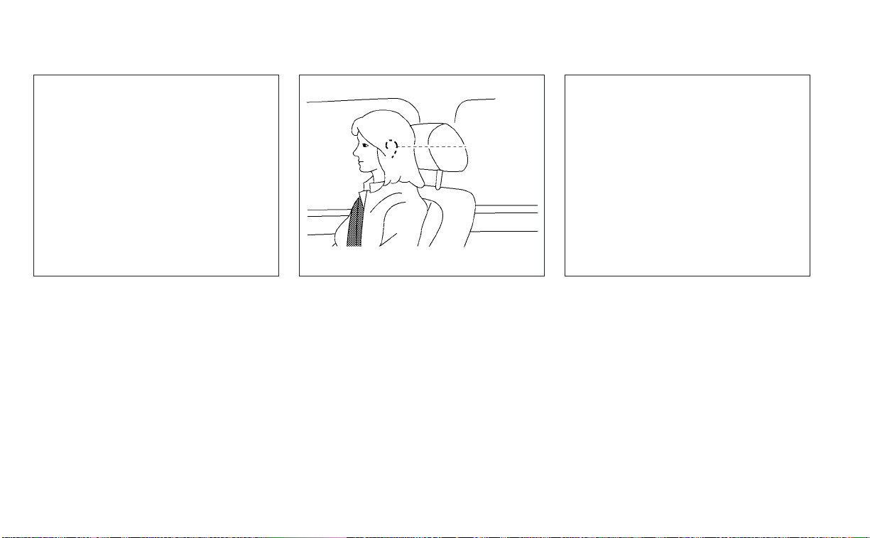
• Proper Adjustment:
– For the adjustable type, align the head
restraint/headrest so the center of
your ear is approximately level with the
center of the head restraint/headrest.
– If your ear position is still higher than
the recommended alignment, place
the head restraint/headrest at the
highest position.
• If the head restraint/headrest has been
removed, ensure that it is reinstalled and
locked in place before riding in that des-
ignated seating position.
ADJUSTABLE HEAD RESTRAINT/
HEADREST COMPONENTS
1. Removable head restraint/headrest
2. Multiple notches
3. Lock knob
4. Stalks
LRS2695 LRS2300
1-8 Safety-Seats, seat belts and supplemental restraint system

NON-ADJUSTABLE HEAD
RESTRAINT/HEADREST
COMPONENTS
1. Removable head restraint/headrest
2. Single notch
3. Lock knob
4. Stalks
REMOVE
Use the following procedure to remove the
head restraint/headrest:
1. Pull the head restraint/headrest up to
the highest position.
2. Push and hold the lock knob.
3. Remove the head restraint/headrest
from the seat.
4. Store the head restraint/headrest prop-
erly in a secure place so it is not loose in
the vehicle.
5. Reinstall and properly adjust the head
restraint/headrest before an occupant
uses the seating position.
LRS2299 LRS2302
Safety-Seats, seat belts and supplemental restraint system 1-9
INSTALL
1. Align the head restraint/headrest stalks
with the holes in the seat. Make sure that
the head restraint/headrest is facing the
correct direction. The stalk with the
notch (notches)
O
1
must be installed in
the hole with the lock knob
O
2
.
2. Push and hold the lock knob and push
the head restraint/headrest down.
3. Properly adjust the head restraint/
headrest before an occupant uses the
seating position.
ADJUST
For adjustable head restraint/headrest
Adjust the head restraint/headrest so the
center is level with the center of your ears. If
your ear position is still higher than the
recommended alignment, place the head
restraint/headrest at the highest position.
For non-adjustable head restraint/headrest
Make sure the head restraint/headrest is
positioned so the lock knob is engaged in
the notch before riding in that designated
seating position.
LRS2303 WRS0134 LRS2351
1-10 Safety-Seats, seat belts and supplemental restraint system

Raise
To raise the head restraint/headrest, pull it
up.
Make sure the head restraint/headrest is
positioned so the lock knob is engaged in
the notch before riding in that designated
seating position.
Lower
To lower, push and hold the lock knob and
push the head restraint/headrest down.
Make sure the head restraint/headrest is
positioned so the lock knob is engaged in
the notch before riding in that designated
seating position.
LRS2305 LRS2306
Safety-Seats, seat belts and supplemental restraint system 1-11
PRECAUTIONS ON SEAT BELT
USAGE
If you are wearing your seat belt properly
adjusted and you are sitting upright and
well back in your seat with both feet on the
floor, your chances of being injured or killed
in a collision and/or the severity of injury
may be greatly reduced. NISSAN strongly
encourages you and all of your passengers
to buckle up every time you drive, even if
your seating position includes a supple-
mental air bag.
Most U.S. states and Canadian provinces
or territories specify that seat belts be
worn at all times when a vehicle is being
driven.
WARNING
• Every person who drives or rides in
this vehicle should use a seat belt at
all times. Children should be in the
rear seats and in an appropriate
restraint.
SSS0136 SSS0016
SEAT BELTS
1-12 Safety-Seats, seat belts and supplemental restraint system
WARNING
• The seat belt should be properly ad-
justed to a snug fit. Failure to do so
may reduce the effectiveness of the
entire restraint system and increase
the chance or severity of injury in an
accident. Serious injury or death can
occur if the seat belt is not worn
properly.
WARNING
• Always route the shoulder belt over
your shoulder and across your chest.
Never put the belt behind your back,
under your arm or across your neck.
The belt should be away from your
face and neck, but not falling off your
shoulder.
• Position the lap belt as low and snug
as possible AROUND THE HIPS, NOT
THE WAIST. A lap belt worn too high
could increase the risk of internal in-
juries in an accident.
SSS0134 SSS0014
Safety-Seats, seat belts and supplemental restraint system 1-13

• Be sure the seat belt tongue is se-
curely fastened to the proper buckle.
• Do not wear the seat belt inside out
or twisted. Doing so may reduce its
effectiveness.
• Do not allow more than one person
to use the same seat belt.
• Never carry more people in the ve-
hicle than there are seat belts.
• If the seat belt warning light glows
continuously while the ignition is
turned ON with all doors closed and
all seat belts fastened, it may indi-
cate a malfunction in the system.
Have the system checked. It is rec-
ommended that you visit a NISSAN
dealer for this service.
• No changes should be made to the
seat belt system. For example, do not
modify the seat belt, add material, or
install devices that may change the
seat belt routing or tension. Doing so
may affect the operation of the seat
belt system. Modifying or tampering
with the seat belt system may result
in serious personal injury.
• Once seat belt pretensioner(s) have
activated, they cannot be reused and
must be replaced together with the
retractor. It is recommended that you
visit a NISSAN dealer for this service.
• All seat belt assemblies, including re-
tractors and attaching hardware,
should be inspected after any colli-
sion. It is recommended that you visit
a NISSAN dealer for this service.
NISSAN recommends that all seat
belt assemblies in use during a colli-
sion be replaced unless the collision
was minor and the belts show no
damage and continue to operate
properly. Seat belt assemblies not in
use during a collision should also be
inspected and replaced if either
damage or improper operation is
noted.
• All child restraints and attaching
hardware should be inspected after
any collision. Always follow the re-
straint manufacturer's inspection in-
structions and replacement recom-
mendations. The child restraints
should be replaced if they are
damaged.
SEAT BELT WARNING LIGHT AND
CHIME
The driver and front passenger seat is
equipped with an enhanced seat belt re-
minder function. If your vehicle is equipped
with an enhanced seat belt reminder func-
tion, a visual and audible alert will operate if
a driver or front passenger seat belt is un-
buckled at speeds of approximately 9 mph
(15 km/h) or more under the following con-
ditions:
• If the driver seat belt is not fastened.
LRS0786
1-14 Safety-Seats, seat belts and supplemental restraint system

• The front passenger’s seat belt is not fas-
tened and the seat is occupied by a pas-
senger for 7 seconds after the ignition
switch is placed in the ON position.
• The front passenger’s seat belt is not fas-
tened and objects or external force on
the passenger seat change the seat belt
reminder classification to Occupied.
The seat belt warning light will flash under
the conditions shown above until the nec-
essary seat belt is securely fastened.
A warning chime will sound for approxi-
mately 90 seconds or until one of the fol-
lowing conditions is met:
• The unbuckled front occupant’s seat belt
is securely fastened.
• The seat belt reminder function in the
front passenger seat no longer detects
that the front passenger seat is occupied.
• The ignition is turned off or the vehicle is
placed in P (Park).
The below situations could result in the
seat belt reminder light being illuminated
and the chime sounding, even with no oc-
cupant present in the passenger seat:
• Heavy objects placed on the seat.
• Someone pushing or pulling on the front
passenger seat.
• An object placed under the front passen-
ger seat.
• An object placed between the seat cush-
ion and center console or between the
seat cushion and the door.
• An object hanging on the seat or placed
in the seatback pocket.
• A child restraint or other object pressing
against the rear of the seatback.
PREGNANT WOMEN
NISSAN recommends that pregnant
women use seat belts. The seat belt should
be worn snug and always position the lap
belt as low as possible around the hips, not
the waist. Place the shoulder belt over your
shoulder and across your chest. Never run
the lap/shoulder belt over your abdominal
area. Contact your doctor for specific
recommendations.
INJURED PERSONS
NISSAN recommends that injured persons
use seat belts. Check with your doctor for
specific recommendations.
THREE-POINT TYPE SEAT BELT
WITH RETRACTOR
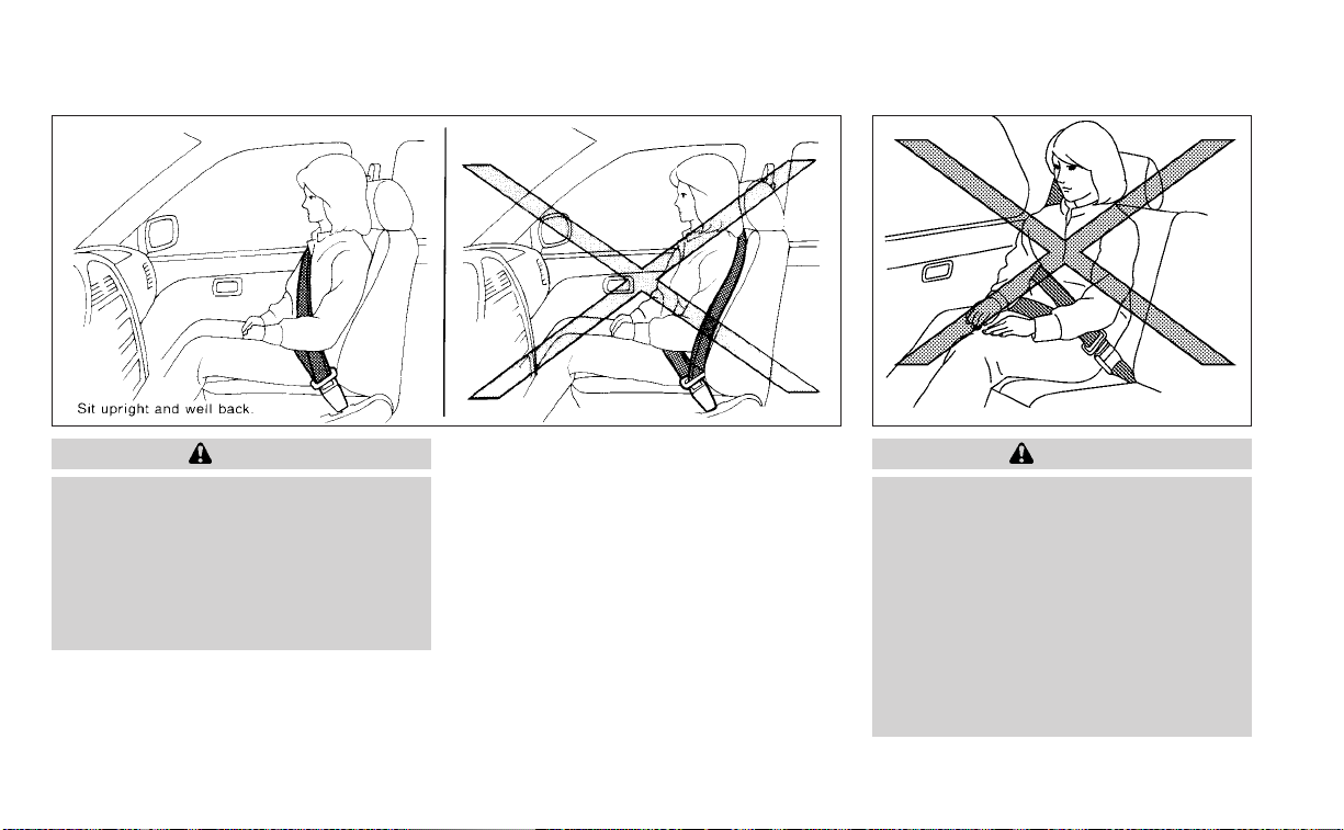
WARNING
• Every person who drives or rides in
this vehicle should use a seat belt at
all times. Children should be in the
rear seats and in an appropriate
restraint.
• Do not ride in a moving vehicle when
the seatback is reclined. This can be
dangerous. The shoulder belt will not
be against your body. In an accident,
you could be thrown into it and re-
ceive neck or other serious injuries.
You could also slide under the lap belt
and receive serious internal injuries.
• For the most effective protection
when the vehicle is in motion, the
seat should be upright. Always sit
well back and upright in the seat with
both feet on the floor and adjust the
seat belt properly.
Safety-Seats, seat belts and supplemental restraint system 1-15

• Do not allow children to play with the
seat belts. Most seating positions are
equipped with Automatic Locking
Retractor (ALR) mode seat belts. If
the seat belt becomes wrapped
around a child’s neck with the ALR
mode activated, the child can be se-
riously injured or killed if the seat belt
retracts and becomes tight. This can
occur even if the vehicle is parked.
Unbuckle the seat belt to release the
child. If the seat belt cannot be un-
buckled or is already unbuckled, re-
lease the child by cutting the seat
belt with a suitable tool (such as a
knife or scissors) to release the seat
belt.
Fastening the seat belts
1. Adjust the seat. For additional informa-
tion, see “Seats” (P. 1-2).
LRS3029
Manual front seat shown
(if so equipped for passenger’s seat)
1-16 Safety-Seats, seat belts and supplemental restraint system

2. Slowly pull the seat belt out of the retrac-
tor and insert the tongue into the buckle
O
A
until you hear and feel the latch
engage.
•
The retractor is designed to lock dur-
ingasuddenstoporonimpact.A
slow pulling motion permits the seat
belt to move and allows you some
freedom of movement in the seat.
• If the seat belt cannot be pulled
from its fully retracted position,
firmly pull the belt and release it.
Then smoothly pull the belt out of
the retractor.
LRS2662
Power front seat shown (for driver’s seat and if so equipped for passenger’s seat)
LRS2674
Safety-Seats, seat belts and supplemental restraint system 1-17

3. Position the lap belt portion low and
snug on the hips
O
B
as shown.
4. Pull the shoulder belt portion toward the
retractor to take up extra slack
O
C
.Be
sure the shoulder belt is routed over
your shoulder and across your chest.
The front passenger seat and the rear
seating positions’ three-point seat belts
have two modes of operation:
• Emergency Locking Retractor (ELR)
• Automatic Locking Retractor (ALR)
The ELR mode allows the seat belt to ex-
tend and retract to allow the driver and
passengers some freedom of movement
in the seat. The ELR locks the seat belt
when the vehicle slows down rapidly or
during certain impacts.
The ALR mode (child restraint mode) locks
the seat belt for child restraint installation.
When the ALR mode is activated, the seat
belt cannot be extended again until the
seat belt tongue is detached from the
buckle and fully retracted. The seat belt re-
turns to the ELR mode after the seat belt
fully retracts. For additional information,
see “Child restraints” (P. 1-23).
The ALR mode should be used only for
child restraint installation. During nor-
mal seat belt use by an occupant, the ALR
mode should not be activated. If it is ac-
tivated, it may cause uncomfortable seat
belt tension. It can also change the op-
eration of the front passenger air bag.
For additional information, see “Front
passenger air bag and status light”
(P. 1-57).
WARNING
When fastening the seat belts, be cer-
tain that the seatbacks are completely
secured in the latched position. If they
are not completely secured, passen-
gers may be injured in an accident or
sudden stop.
LRS2675
1-18 Safety-Seats, seat belts and supplemental restraint system
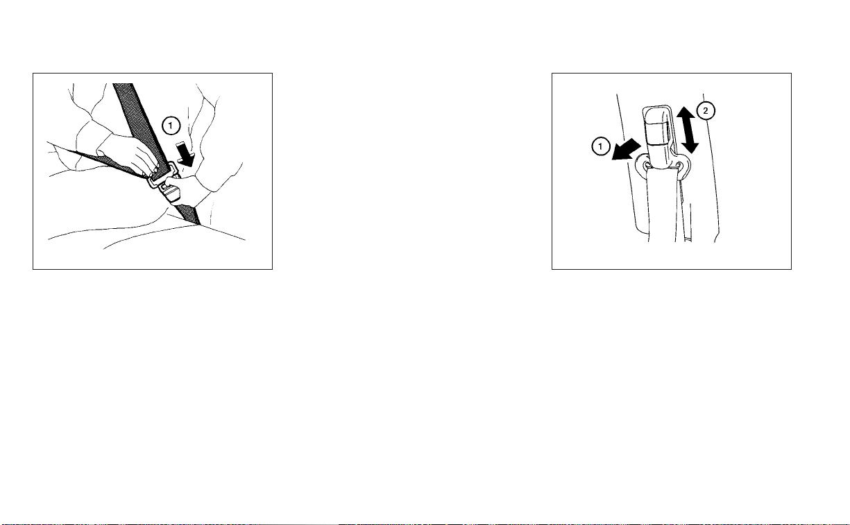
Unfastening the seat belts
To unfasten the seat belt, press the button
on the buckle
O
1
. The seat belt automati-
cally retracts.
Checking seat belt operation
Seat belt retractors are designed to lock
seat belt movement by two separate
methods:
• When the seat belt is pulled quickly from
the retractor
• When the vehicle slows down rapidly
To increase your confidence in the seat
belts, check the operation as follows:
• Grasp the shoulder belt and pull forward
quickly. The retractor should lock and re-
strict further belt movement.
If the retractor does not lock during this
check, get the system checked. It is recom-
mended that you visit a NISSAN dealer for
this service or to learn more about seat belt
operation.
Shoulder belt height adjustment
(front seats)
The shoulder belt anchor height should be
adjusted to the position best for you. For
additional information, see “Precautions on
seat belt usage” (P. 1-12). To adjust, pull out
the adjustment button
O
1
and move the
shoulder belt anchor to the desired posi-
tion
O
2
, so the belt passes over the center
of the shoulder. The belt should be away
from your face and neck, but not falling off
your shoulder.Release the adjustment but-
ton to lock the shoulder belt anchor into
position.
WRS0139 LRS0242
Safety-Seats, seat belts and supplemental restraint system 1-19

WARNING
• After adjustment, release the adjust-
ment button and try to move the
shoulder belt anchor up and down to
make sure it is securely fixed in
position.
• The shoulder belt anchor height
should be adjusted to the position
best for you. Failure to do so may re-
duce the effectiveness of the entire
restraint system and increase the
chance or severity of injury in an
accident.
SEAT BELT EXTENDERS
If, because of body size or driving position, it
is not possible to properly fit the lap/
shoulder belt and fasten it, an extender
that is compatible with the installed seat
belts is available for purchase. The ex-
tender adds approximately 8 in (200 mm)
of length and may be used for either the
driver or front passenger seating position.
It is recommended that you visit a NISSAN
dealer for assistance with purchasing an
extender if an extender is required.
WARNING
• Only NISSAN seat belt extenders,
made by the same company which
made the original equipment seat
belts, should be used with NISSAN
seat belts.
• Adults and children who can use the
standard seat belt should not use an
extender. Such unnecessary use
could result in serious personal injury
in the event of an accident.
• Never use seat belt extenders to in-
stall child restraints. If the child re-
straint is not secured properly, the
child could be seriously injured or
killed in a collision or a sudden stop.
SEAT BELT MAINTENANCE
• To clean the seat belt webbing, apply a
mild soap solution or any solution rec-
ommended for cleaning upholstery or
carpet. Then wipe with a cloth and allow
the seat belts to dry in the shade. Do not
allow the seat belts to retract until they
are completely dry.
• If dirt builds up in the shoulder belt
guide of the seat belt anchors, the seat
belts may retract slowly. Wipe the shoul-
der belt guide with a clean, dry cloth.
• Periodically check to see that the seat
belt and the metal components, such
as buckles, tongues, retractors, flexible
wires and anchors, work properly. If loose
parts, deterioration, cuts or other dam-
age on the webbing is found, the entire
seat belt assembly should be replaced.
1-20 Safety-Seats, seat belts and supplemental restraint system

WARNING
Do not allow children to play with the
seat belts. Most seating positions are
equipped with Automatic Locking Re-
tractor (ALR) mode seat belts. If the seat
belt becomes wrapped around a child’s
neck with the ALR mode activated, the
child can be seriously injured or killed if
the seat belt retracts and becomes
tight. This can occur even if the vehicle
is parked. Unbuckle the seat belt to re-
lease the child. If the seat belt cannot
be unbuckled or is already unbuckled,
release the child by cutting the seat
belt with a suitable tool (such as a knife
or scissors) to release the seat belt.
Children need adults to help protect
them. They need to be properly
restrained.
In addition to the general information in
this manual, child safety information is
available from many other sources, includ-
ing doctors, teachers, government traffic
safety offices, and community organiza-
tions. Every child is different, so be sure to
learn the best way to transport your child.
There are three basic types of child re-
straint systems:
• Rear-facing child restraints
• Forward-facing child restraints
• Booster seats
The proper restraint depends on the child's
size. Generally, infants up to about 1 year
and less than 20 lbs. (9 kg) should be placed
in rear-facing child restraints. Forward-
facing child restraints are available for chil-
dren who outgrow rear-facing child re-
straints and are at least 1 year old. Booster
seats are used to help position a vehicle
lap/shoulder belt on a child who can no
longer use a forward-facing child restraint.
WARNING
Infants and children need special pro-
tection. The vehicle's seat belts may
not fit them properly. The shoulder belt
may come too close to the face or neck.
The lap belt may not fit over their small
hip bones. In an accident, an improp-
erly fitting seat belt could cause serious
or fatal injury. Always use appropriate
child restraints.
All U.S. states and Canadian provinces or
territories require the use of approved child
restraints for infants and small children. For
additional information, see “Child re-
straints” (P. 1-23).
A child restraint may be secured in the ve-
hicle by using either the LATCH (Lower An-
chors and Tethers for CHildren) system or
with the vehicle seat belt. For additional
information, see “Child restraints” (P. 1-23).
NISSAN recommends that all pre-teens
and children be restrained in the rear
seat. Studies show that children are
safer when properly restrained in the
rear seat than in the front seat.
This is especially important because
your vehicle has a supplemental re-
straint system (air bag system) for the
front passenger. For additional informa-
tion, see “Supplemental Restraint Sys-
tem (SRS)” (P. 1-46).
INFANTS
Infants up to at least 1 year old should be
placed in a rear-facing child restraint.
NISSAN recommends that infants be
placed in child restraints that comply with
Federal Motor Vehicle Safety Standards or
Canadian Motor Vehicle Safety Standards.
You should choose a child restraint that fits
your vehicle and always follow the manu-
facturer's instructions for installation and
use.
CHILD SAFETY
Safety-Seats, seat belts and supplemental restraint system 1-21

SMALL CHILDREN
Children that are over 1 year old and weigh
at least 20 lbs. (9 kg) should remain in a
rear-facing child restraint as long as pos-
sible up to the height or weight limit of the
child restraint. Children who outgrow the
height or weight limit of the rear-facing
child restraint and are at least 1 year old
should be secured in a forward-facing child
restraint with a harness. Refer to the manu-
facturer’s instructions for minimum and
maximum weight and height recommen-
dations. NISSAN recommends that small
children be placed in child restraints that
comply with Federal Motor Vehicle Safety
Standards or Canadian Motor Vehicle
Safety Standards. You should choose a
child restraint that fits your vehicle and al-
ways follow the manufacturer’s instruc-
tions for installation and use.
LARGER CHILDREN
Children should remain in a forward-facing
child restraint with a harness until they
reach the maximum height or weight limit
allowed by the child restraint
manufacturer.
Once a child outgrows the height or weight
limit of the harness-equipped for ward-
facing child restraint, NISSAN recommends
that the child be placed in a commercially
available booster seat to obtain proper
seat belt fit. For a seat belt to fit properly, the
booster seat should raise the child so that
the shoulder belt is properly positioned
across the chest and the top, middle por-
tion of the shoulder. The shoulder belt
should not cross the neck or face and
should not fall off the shoulder. The lap belt
should lie snugly across the lower hips or
upper thighs, not the abdomen. A booster
seat can only be used in seating positions
that have a three-point type seat belt. The
booster seat should fit the vehicle seat and
have a label certifying that it complies with
Federal Motor Vehicle Safety Standards or
Canadian Motor Vehicle Safety Standards.
A booster seat should be used until the
child can pass the seat belt fit test below:
• Are the child’s back and hips against the
vehicle seatback?
• Is the child able to sit without slouching?
• Do the child’s knees bend easily over the
front edge of the seat with feet flat on the
floor?
• Can the child safely wear the seat belt (lap
belt low and snug across the hips and
shoulder belt across mid-chest and
shoulder)?
• Is the child able to use the properly ad-
justed head restraint/headrest?
• Will the child be able to stay in position for
the entire ride?
1-22 Safety-Seats, seat belts and supplemental restraint system
If you answered no to any of these ques-
tions, the child should remain in a booster
seat using a three-point type seat belt.
NOTE:
Laws in some communities may follow
different guidelines. Check local and
state regulations to confirm your child is
using the correct restraint system before
traveling.
WARNING
Never let a child stand or kneel on any
seat and do not allow a child in the
cargo area. The child could be seriously
injured or killed in a sudden stop or
collision.
PRECAUTIONS ON CHILD
RESTRAINTS
WARNING
•
Failure to follow the warnings and in-
structions for proper use and installa-
tion of child restraints could result in se-
rious injury or death of a child or other
passengers in a sudden stop or collision:
–
The child restraint must be used and
installed properly. Always follow all
of the child restraint manufacturer's
instructions for installation and use.
LRS2690 ARS1098
CHILD RESTRAINTS
Safety-Seats, seat belts and supplemental restraint system 1-23
– Infants and children should never
be held on anyone's lap. Even the
strongest adult cannot resist the
forces of a collision.
– Do not put a seat belt around both
a child and another passenger.
– NISSAN recommends that all child
restraints be installed in the rear
seat. Studies show that children
are safer when properly re-
strained in the rear seat than in
the front seat. If you must install a
forward-facing child restraint in
the front seat, see “Forward-
facing child restraint installation
using the seat belts” (P. 1-38).
– Even with the NISSAN Advanced
Air Bag System, never install a
rear-facing child restraint in the
front seat. An inflating air bag
could seriously injure or kill a child.
A rear-facing child restraint must
only be used in the rear seat.
– Be sure to purchase a child re-
straint that will fit the child and
vehicle. Some child restraints may
not fit properly in your vehicle.
– Child restraint anchorages are de-
signed to withstand only those
loads imposed by correctly fitted
child restraints. Under no circum-
stances are they to be used to at-
tach adult seat belts, or other
items or equipment to the vehicle.
Doing so could damage the child
restraint anchorages. The child re-
straint will not be properly in-
stalled using the damaged an-
chorage, and a child could be
seriously injured or killed in a
collision.
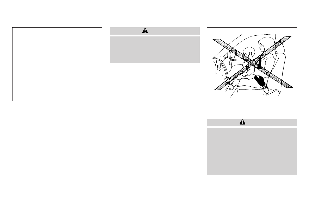
– Never use the anchor points for
adult seat belts, or other items.
– A child restraint with a top tether
strap should not be used in the
front passenger seat.
– Keep seatbacks as upright as pos-
sible after fitting the child
restraint.
– Infants and children should al-
ways be placed in an appropriate
child restraint while in the vehicle.
• When the child restraint is not in use,
keep it secured with the LATCH sys-
tem or a seat belt. In a sudden stop or
collision, loose objects can injure oc-
cupants or damage the vehicle.
CAUTION
A child restraint in a closed vehicle can
become very hot. Check the seating
sur face and buckles before placing a
child in the child restraint.
WRS0256
1-24 Safety-Seats, seat belts and supplemental restraint system

This vehicle is equipped with a universal
child restraint anchor system, referred to
as the LATCH (Lower Anchors and Tethers
for CHildren) system. Some child restraints
include rigid or webbing-mounted attach-
ments that can be connected to these an-
chors. For additional information, see
“LATCH (Lower Anchors and Tethers for
CHildren) system” (P. 1-25).
If you do not have a LATCH compatible
child restraint, the vehicle seat belts can be
used.
Several manufacturers offer child re-
straints for infants and children of various
sizes. When selecting any child restraint,
keep the following points in mind:
• Choose only a restraint with a label certi-
fying that it complies with Federal Motor
Vehicle Safety Standard 213 or Canadian
Motor Vehicle Safety Standard 213.
• Check the child restraint in your vehicle to
be sure it is compatible with the vehicle's
seat and seat belt system.
• If the child restraint is compatible with
your vehicle, place your child in the child
restraint and check the various adjust-
ments to be sure the child restraint is
compatible with your child. Choose a
child restraint that is designed for your
child's height and weight. Always follow
all recommended procedures.
• If the combined weight of the child and
child restraint is less than 65 lbs. (29.5 kg),
you may use either the LATCH anchors or
the seat belt to install the child restraint
(not both at the same time).
• If the combined weight of the child and
child restraint is greater than 65 lbs. (29.5
kg), use the vehicle’s seat belt (not the
lower anchors) to install the child
restraint.
• Be sure to follow the child restraint
manufacturer’s instructions for
installation.
All U.S. states and Canadian provinces or
territories require that infants and small
children be restrained in an approved
child restraint at all times while the ve-
hicle is being operated. Canadian law re-
quires the top tether strap on forward-
facing child restraints be secured to the
designated anchor point on the vehicle.
LATCH (Lower Anchors and
Tethers for CHildren) SYSTEM
Your vehicle is equipped with special an-
chor points that are used with LATCH sys-
tem compatible child restraints. This sys-
tem may also be referred to as the ISOFIX
or ISOFIX compatible system. With this sys-
tem, you do not have to use a vehicle seat
belt to secure the child restraint unless the
combined weight of the child and child re-
straint exceeds 65 lbs. (29.5 kg). If the com-
bined weight of the child and child restraint
is greater than 65 lbs. (29.5 kg), use the ve-
hicle’s seat belt (not the lower anchors) to
LRS3285
LATCH system anchor locations
Safety-Seats, seat belts and supplemental restraint system 1-25

install the child restraint. Be sure to follow
the child restraint manufacturer’s instruc-
tions for installation.
The LATCH anchor points can be used to
install child restraints in either of the rear
outboard seating positions or in the center
rear seating position. Please refer to the
following section of this Owner’s Manual for
specific information about installing a child
restraint in the center rear seating position
using the LATCH anchors.
LATCH lower anchor
WARNING
Failure to follow the warnings and in-
structions for proper use and installa-
tion of child restraints could result in
serious injury or death of a child or
other passengers in a sudden stop or
collision:
– Only attach LATCH system compat-
ible child restraints to the Lower An-
chors shown in the illustration. For
additional information, refer to the
following sections of this Owner’s
Manual for installation guidance.
– Inspect the lower anchors by insert-
ing your fingers into the lower an-
chor area. Feel to make sure there
are no obstructions over the an-
chors such as seat belt webbing or
seat cushion material. The child re-
straint will not be secured properly if
the lower anchors are obstructed.
Child restraint anchorages are de-
signed to withstand only those loads
imposed by correctly fitted child re-
straints. Under no circumstances are
they to be used to attach adult seat
belts, or other items or equipment to
the vehicle. Doing so could damage the
child restraint anchorages. The child
restraint will not be properly installed
using the damaged anchorage, and a
child could be seriously injured or killed
in a collision.
LATCH lower anchor location
The LATCH lower anchors are located as
shown. A label is attached to the seatback
to help you locate the LATCH lower
anchors.
LRS3036
LATCH lower anchor location
1-26 Safety-Seats, seat belts and supplemental restraint system
LATCH in the center rear seating
position
There are no LATCH anchors dedicated to
the center rear seating position. However,
the inboard LATCH anchors belonging to
the two outboard seating positions (indi-
cated by the arrows) can be used together
to secure a CRS in the center rear seating
position. These anchors are separated by a
distance
O
A
of 16 in (408 mm). Before at-
tempting to secure a CRS in this seating
position, ensure that the CRS manufactur-
er’s instructions permit the use of LATCH
anchors with the spacing indicated above.
(These are sometimes referred to as
“shared anchors” or “borrowed anchors.”)
CRS with rigid lower attachments cannot
be installed in the center seat. This type of
CRS should only be installed in the out-
board seating positions.
WARNING
• Never attach two CRS attachments
to the same LATCH anchor. This may
overload the anchor in a collision,
which could increase the risk of the
occupant’s serious injury or death.
• When installing the CRS in the center
rear seating position with the in-
board LATCH anchors, be careful to
ensure any occupant or CRS in the
outboard seating positions is prop-
erly restrained using the vehicle seat
belt and there is no interference with
the center CRS installation. If the out-
board occupants cannot be properly
restrained, consider using the vehicle
seat belt to restrain the CRS in the
center seating position, or moving
the CRS to another position instead.
Installing child restraint LATCH
lower anchor attachments
LATCH compatible child restraints include
two rigid or webbing-mounted attach-
ments that can be connected to two an-
chors located at certain seating positions
in your vehicle. With this system, you do not
have to use a vehicle seat belt to secure the
child restraint.Check your child restraint for
a label stating that it is compatible with
LATCH. This information may also be in the
instructions provided by the child restraint
manufacturer.
LRS3269 LRS0661
LATCH webbing-mounted attachment
Safety-Seats, seat belts and supplemental restraint system 1-27
When installing a child restraint, carefully
read and follow the instructions in this
manual and those supplied with the child
restraint.
Top tether anchor point locations
The child restraint top tether strap must be
used when installing the child restraint with
the LATCH lower anchor attachments or
seat belts. For additional information, see
“Installing top tether strap” (P. 1-37).
WARNING
Child restraint anchorages are de-
signed to withstand only those loads
imposed by correctly fitted child re-
straints. Under no circumstances are
they to be used to attach adult seat
belts, or other items or equipment to
the vehicle. Doing so could damage the
child restraint anchorages. The child
restraint will not be properly installed
using the damaged anchorage, and a
child could be seriously injured or killed
in a collision.
If you have any questions when install-
ing a top tether strap, it is recommended
that you visit a NISSAN dealer for this
service.
Anchor points
O
1
are located on the rear
parcel shelf.
LRS0662
LATCH rigid-mounted attachment
LRS3284
1-28 Safety-Seats, seat belts and supplemental restraint system

REAR-FACING CHILD RESTRAINT
INSTALLATION USING LATCH
For additional information, see all Warnings
and Cautions in the “Child safety” (P. 1-21)
and “Child restraints” (P. 1-23) before install-
ing a child restraint.
Do not use the lower anchors if the com-
bined weight of the child and the child re-
straint exceeds 65 lbs. (29.5 kg). If the com-
bined weight of the child and the child
restraint is greater than 65 lbs. (29.5 kg), use
the vehicle's seat belt (not the lower an-
chors) to install the child restraint. Be sure
to follow the child restraint manufacturer's
instructions for installation.
Follow these steps to install a rear-facing
child restraint using the LATCH system:
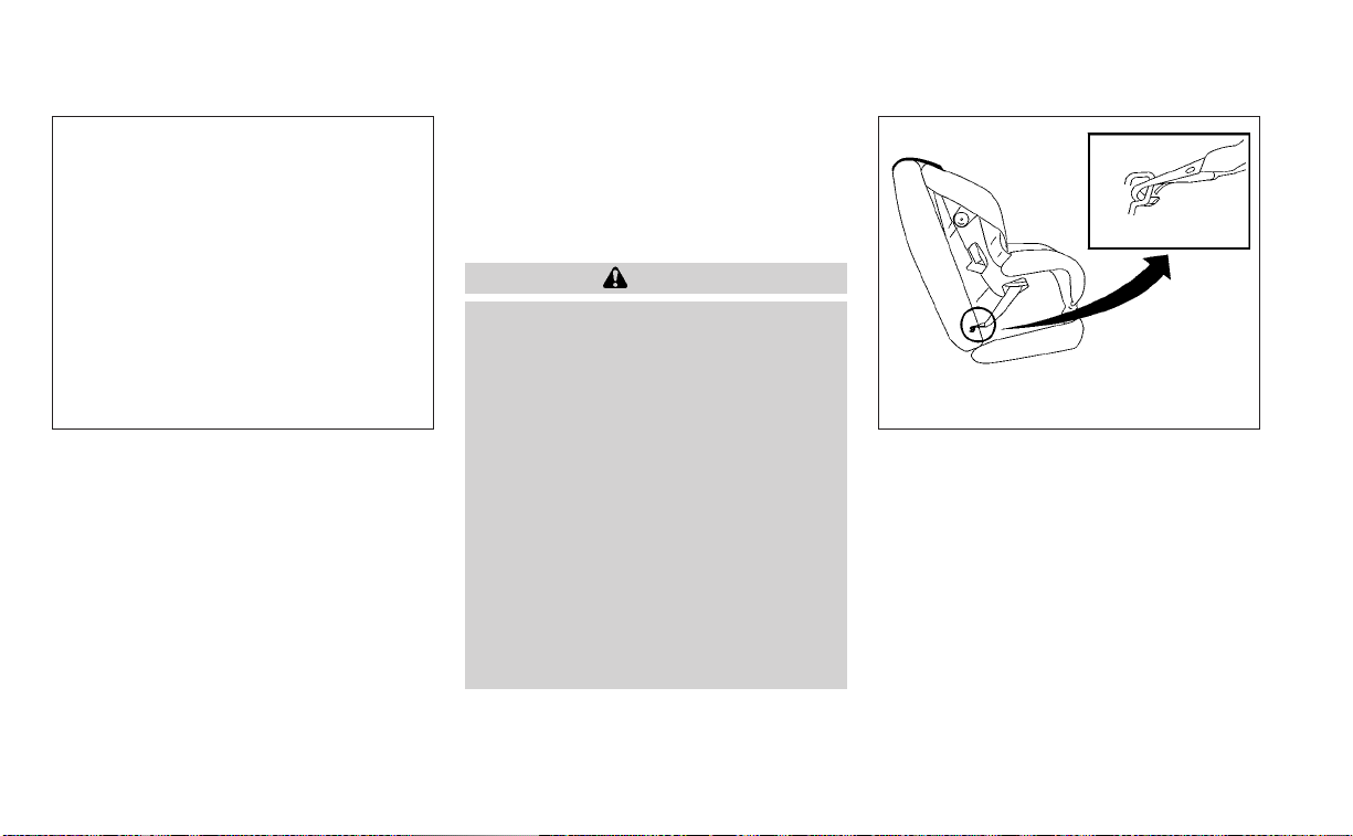
1. Type A (if so equipped):
Remove the plastic covers from the
LATCH anchors by pulling the covers
straight back. Store the covers in a se-
cure area.
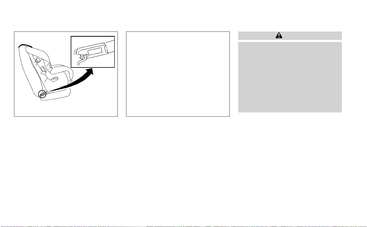
Type B (if so equipped):
Lift the flap of the material to expose the
LATCH anchors.
2. Position the child restraint on the seat.
Always follow the child restraint manu-
facturer's instructions.
LRS3118
Type A (if so equipped) — step 1
LRS3140
Type B (if so equipped) — step 1
Safety-Seats, seat belts and supplemental restraint system 1-29
3. Secure the child restraint anchor at-
tachments to the LATCH lower anchors.
Check to make sure the LATCH attach-
ment is properly attached to the lower
anchors.
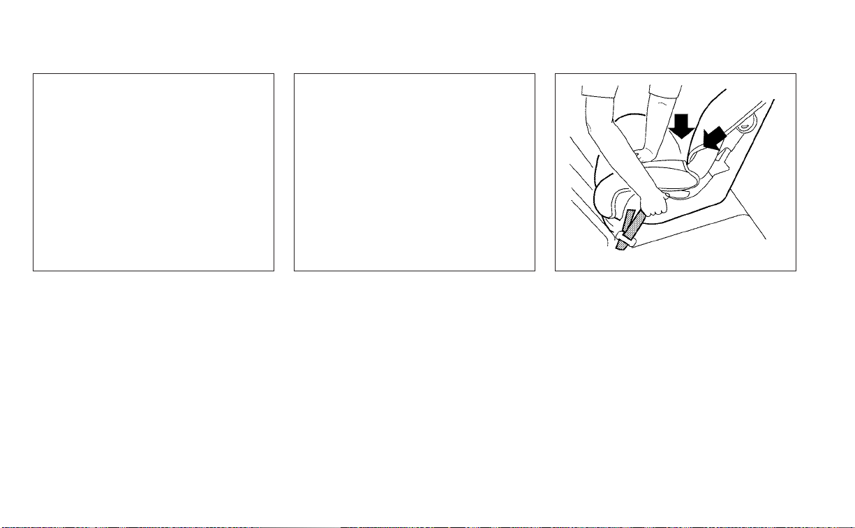
4. For child restraints that are equipped
with webbing-mounted attachments,
remove any additional slack from the
anchor attachments. Press downward
and rearward firmly in the center of the
child restraint with your hand to com-
press the vehicle seat cushion and seat-
back while tightening the webbing of
the anchor attachments.
5. Tighten the tether strap according to
the manufacturer’s instructions to re-
move any slack.
LRS2997
Rear-facing webbing-mounted – step 3
LRS2996
Rear-facing rigid-mounted – step 3
LRS0673
Rear-facing – step 4
1-30 Safety-Seats, seat belts and supplemental restraint system
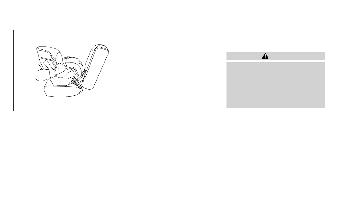
6. After attaching the child restraint, test it
before you place the child in it. Push it
from side to side while holding the child
restraint near the LATCH attachment
path. The child restraint should not
move more than 1 inch (25 mm), from
side to side. Try to tug it forward and
check to see if the LATCH attachment
holds the restraint in place. If the re-
straint is not secure, tighten the LATCH
attachment as necessary, or put the re-
straint in another seat and test it again.
You may need to try a different child
restraint or try installing by using the
vehicle seat belt (if applicable). Not all
child restraints fit in all types of vehicles.
7. Check to make sure the child restraint is
properly secured prior to each use. If the
child restraint is loose, repeat steps 2
through 6.
8. Type A (if so equipped):
If you remove the child restraint, reinstall
the plastic LATCH anchor covers after
use by pushing the covers straight onto
the LATCH anchors.
Type B (if so equipped):
If you remove the child restraint, se-
curely replace the flap by pressing the
material firmly against the seat.
REAR-FACING CHILD RESTRAINT
INSTALLATION USING THE SEAT
BELTS
WARNING
The three-point seat belt with Auto-
matic Locking Retractor (ALR) must be
used when installing a child restraint.
Failure to use the ALR mode will result
in the child restraint not being properly
secured. The restraint could tip over or
be loose and cause injury to a child in a
sudden stop or collision.
For additional information, see all Warnings
and Cautions in the “Child safety” (P. 1-21)
and “Child restraints” (P. 1-23) before install-
ing a child restraint.
Do not use the lower anchors if the com-
bined weight of the child and the child re-
straint exceeds 65 lbs. (29.5 kg). If the com-
bined weight of the child and the child
restraint is greater than 65 lbs. (29.5 kg), use
the vehicle's seat belt (not the lower an-
chors) to install the child restraint. Be sure
to follow the child restraint manufacturer's
instructions for installation.
Follow these steps to install a rear-facing
child restraint using the vehicle seat belts in
the rear seats:
LRS0674
Rear-facing – step 6
Safety-Seats, seat belts and supplemental restraint system 1-31
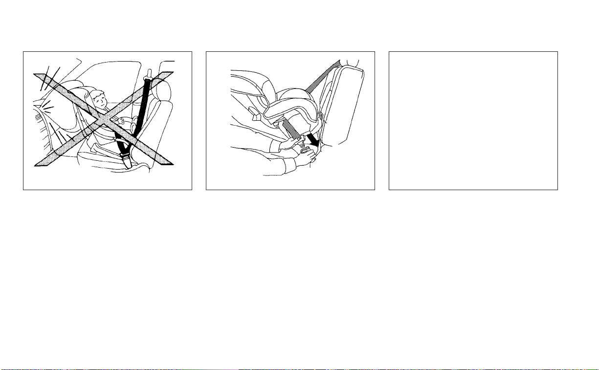
1. Child restraints for infants must be
used in the rear-facing direction and
therefore must not be used in the front
seat. Position the child restraint on the
seat. Always follow the child restraint
manufacturer’s instructions.
2. Route the seat belt tongue through the
child restraint and insert it into the
buckle until you hear and feel the latch
engage. Be sure to follow the child re-
straint manufacturer’s instructions for
belt routing.
3. Pull the shoulder belt until the belt is fully
extended. At this time, the seat belt re-
tractor is in the ALR mode (child restraint
mode). It reverts to the ELR mode when
the seat belt is fully retracted.
WRS0256
Rear-facing – step 1
WRS0761
Rear-facing – step 2
LRS2395
Rear-facing – step 3
1-32 Safety-Seats, seat belts and supplemental restraint system
4. Allow the seat belt to retract. Pull up on
the shoulder belt to remove any slack in
the belt.
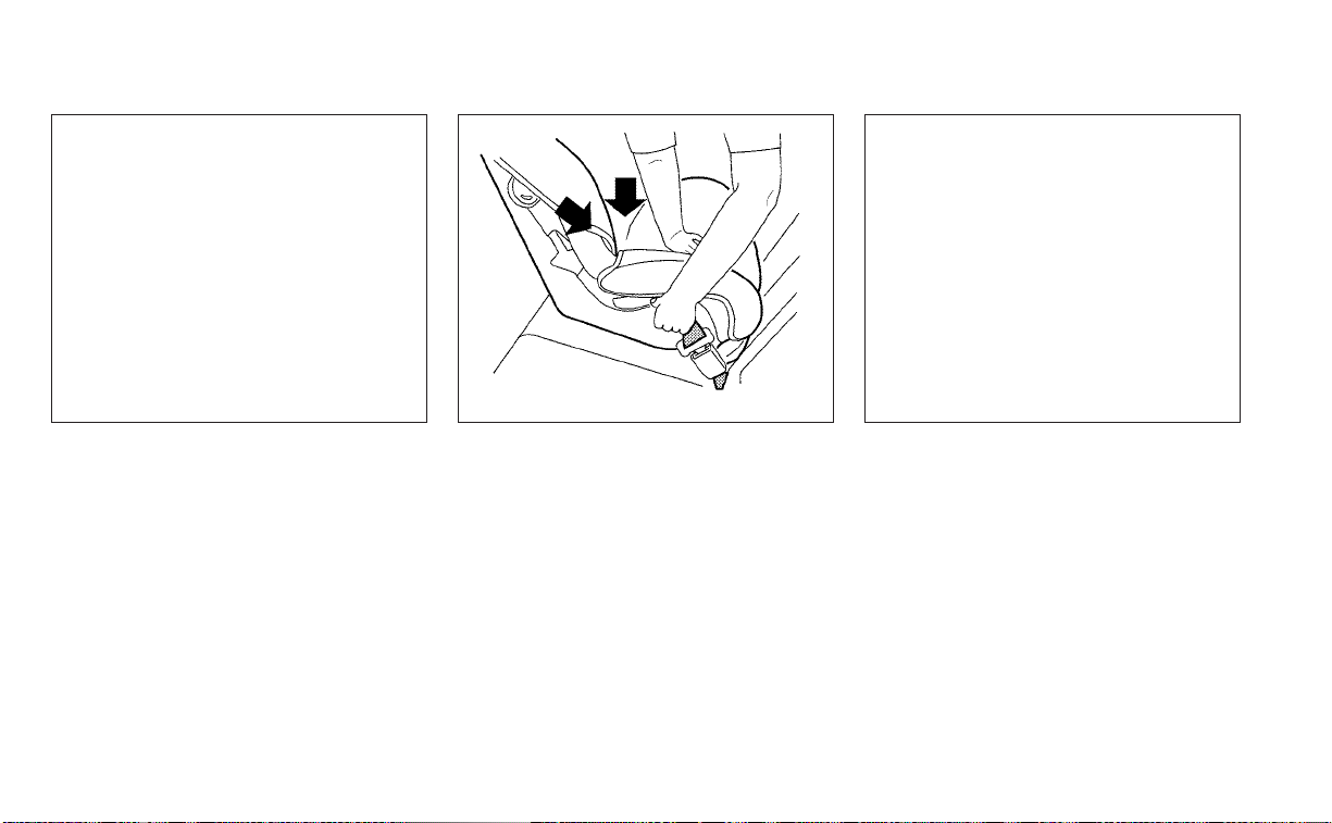
5. Remove any additional slack from the
seat belt; press downward and rearward
firmly in the center of the child restraint
to compress the vehicle seat cushion
and seatback while pulling up on the
seat belt.
6. After attaching the child restraint, test it
before you place the child in it. Push it
from side to side while holding the child
restraint near the seat belt path. The
child restraint should not move more
than 1 inch (25 mm), from side to side. Try
to tug it forward and check to see if the
belt holds the restraint in place. If the
restraint is not secure, tighten the seat
belt as necessary, or put the restraint in
another seat and test it again. You may
need to try a different child restraint. Not
all child restraints fit in all types of
vehicles.
LRS2396
Rear-facing – step 4
WRS0762
Rear-facing – step 5
LRS2397
Rear-facing – step 6
Safety-Seats, seat belts and supplemental restraint system 1-33

7. Check to make sure that the child re-
straint is properly secured prior to each
use. If the seat belt is not locked, repeat
steps 3 through 6.
After the child restraint is removed and the
seat belt fully retracted, the ALR mode
(child restraint mode) is canceled.
FORWARD-FACING CHILD
RESTRAINT INSTALLATION USING
LATCH
For additional information, see all Warnings
and Cautions in “Child safety” (P. 1-21) and
“Child restraints” (P. 1-23) before installing a
child restraint.
Do not use the lower anchors if the com-
bined weight of the child and the child re-
straint exceeds 65 lbs. (29.5 kg). If the com-
bined weight of the child and the child
restraint is greater than 65 lbs. (29.5 kg), use
the vehicle's seat belt (not the lower an-
chors) to install the child restraint. Be sure
to follow the child restraint manufacturer's
instructions for installation.
Follow these steps to install a forward-
facing child restraint using the LATCH
system:
1. Type A (if so equipped):
Remove the plastic covers from the
LATCH anchors by pulling the covers
straight back. Store the covers in a se-
cure area.
Type B (if so equipped):
Lift the flap of the material to expose the
LATCH anchors.
2. Position the child restraint on the seat.
Always follow the child restraint manu-
facturer's instructions.
LRS3118
Type A (if so equipped) – step 1
LRS3140
Type B (if so equipped) – step 1
1-34 Safety-Seats, seat belts and supplemental restraint system

3. Secure the child restraint anchor at-
tachments to the LATCH lower anchors.
Check to make sure the LATCH attach-
ment is properly attached to the lower
anchors.
If the child restraint is equipped with a
top tether strap, route the top tether
strap and secure the tether strap to the
tether anchor point. For additional infor-
mation, see “Installing top tether strap”
(P. 1-37).
Do not install child restraints that require
the use of a top tether strap in seating
positions that do not have a top tether
anchor.
4. The back of the child restraint should be
secured against the vehicle seatback.
If necessary, adjust or remove the head
restraint/headrest to obtain the correct
child restraint fit. If the head restraint/
headrest is removed, store it in a secure
place. Be sure to reinstall the head
restraint/headrest when the child re-
straint is removed. For additional infor-
mation about head restraint/headrest
adjustment, see "Head restraints/
headrests" (P. 1-7).
If the seating position does not have an
adjustable head restraint/headrest and
it is interfering with the proper child re-
straint fit, try another seating position or
a different child restraint.
LRS2995
Forward-facing webbing-mounted –
step 3
LRS2994
Forward-facing rigid-mounted – step 3
Safety-Seats, seat belts and supplemental restraint system 1-35
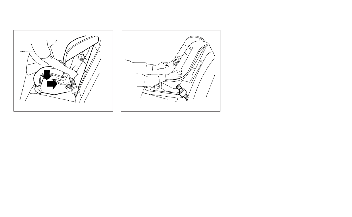
5. For child restraints that are equipped
with webbing-mounted attachments,
remove any additional slack from the
anchor attachments. Press downward
and rearward firmly in the center of the
child restraint with your knee to com-
press the vehicle seat cushion and seat-
back while tightening the webbing of
the anchor attachments.
6. Tighten the tether strap according to
the manufacturer's instructions to re-
move any slack.
7. After attaching the child restraint, test it
before you place the child in it. Push it
from side to side while holding the child
restraint near the LATCH attachment
path. The child restraint should not move
more than 1 inch (25 mm), from side to
side. Try to tug it forward and check to
see if the LATCH attachment holds the
restraint in place. If the restraint is not
secure, tighten the LATCH attachment
as necessary, or put the restraint in an-
other seat and test it again. You may
need to try a different child restraint or
try installing by using the vehicle seat
belt (if applicable). Not all child restraints
fit in all types of vehicles.
8. Check to make sure the child restraint is
properly secured prior to each use. If the
child restraint is loose, repeat steps 2
through 7.
9. Type A (if so equipped):
If you remove the child restraint, reinstall
the plastic LATCH anchor covers after
use by pushing the covers straight onto
the LATCH anchors.
Type B (if so equipped):
If you remove the child restraint, securely
replace the flap by pressing the material
firmly against the seat.
LRS0671
Forward-facing – step 5
WRS0697
Forward-facing – step 7
1-36 Safety-Seats, seat belts and supplemental restraint system

Installing top tether strap
The child restraint top tether strap must be
used when installing the child restraint with
the LATCH lower anchor attachments.
First, secure the child restraint with the
LATCH lower anchors.
Rear bench seat
OUTBOARD SEATING POSITIONS
1. Position the top tether strap
O
1
over the
seatback.
2. Secure the tether strap to the tether an-
chor point
O
2
as shown.
3. Tighten the tether strap according to
the manufacturer’s instructions to re-
move any slack.
CENTER SEATING POSITION
1. Position the top tether strap
O
1
over the
seatback.
2. Secure the tether strap to the tether an-
chor point
O
2
as shown.
3. Tighten the tether strap according to
the manufacturer’s instructions to re-
move any slack.
If you have any questions when install-
ing a top tether strap, it is recommended
that you visit a NISSAN dealer for this
service.
WARNING
Child restraint anchorages are de-
signed to withstand only those loads
imposed by correctly fitted child re-
straints. Under no circumstances are
they to be used to attach adult seat
belts, or other items or equipment to
the vehicle. Doing so could damage the
child restraint anchorages. The child
restraint will not be properly installed
using the damaged anchorage, and a
child could be seriously injured or killed
in a collision.
LRS3283
Rear seats
䊊
1
Top tether strap
䊊
2
Anchor point
Safety-Seats, seat belts and supplemental restraint system 1-37
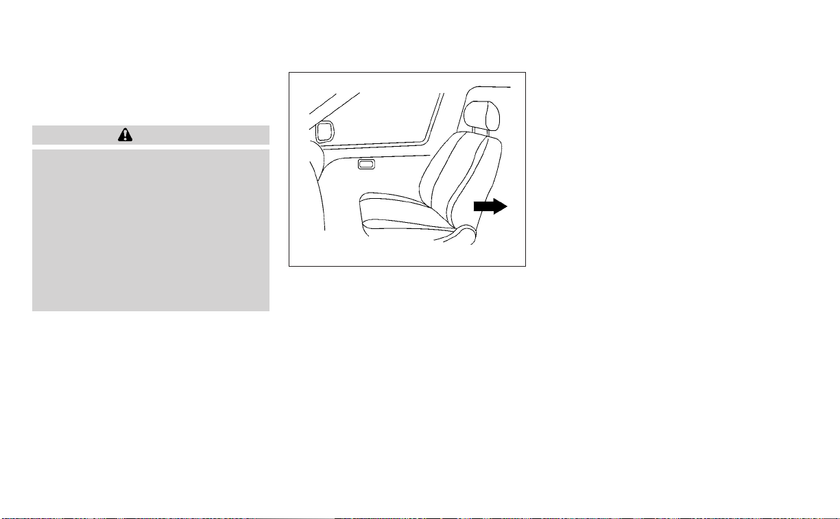
FORWARD-FACING CHILD
RESTRAINT INSTALLATION USING
THE SEAT BELTS
WARNING
The three-point seat belt with Auto-
matic Locking Retractor (ALR) must be
used when installing a child restraint.
Failure to use the ALR mode will result
in the child restraint not being properly
secured. The restraint could tip over or
be loose and cause injury to a child in a
sudden stop or collision. Also, it can
change the operation of the front pas-
senger air bag. For additional informa-
tion, see “Front passenger air bag and
status light” (P. 1-57).
For additional information, see all Warnings
and Cautions in the “Child safety” (P. 1-21)
and “Child restraints” (P. 1-23) before install-
ing a child restraint.
Do not use the lower anchors if the com-
bined weight of the child and the child re-
straint exceeds 65 lbs. (29.5 kg). If the com-
bined weight of the child and the child
restraint is greater than 65 lbs. (29.5 kg), use
the vehicle's seat belt (not the lower an-
chors) to install the child restraint. Be sure
to follow the child restraint manufacturer's
instructions for installation.
Follow these steps to install a forward-
facing child restraint using the vehicle seat
belt in the rear seats or in the front passen-
ger seat:
1. If you must install a child restraint in
the front seat, it should be placed in a
forward-facing direction only. Move
the seat to the rearmost position.
Child restraints for infants must be
used in the rear-facing direction and,
therefore, must not be used in the
front seat.
2. Position the child restraint on the seat.
Always follow the child restraint manu-
facturer’s instructions.
The back of the child restraint should be
secured against the vehicle seatback.
If necessary, adjust or remove the head
restraint/headrest to obtain the correct
child restraint fit. If the head restraint/
headrest is removed, store it in a secure
place. Be sure to reinstall the head
restraint/headrest when the child re-
straint is removed. For additional infor-
mation about head restraint/headrest
adjustment, removal and installation,
see “Head restraints/headrests” (P. 1-7).
WRS0699
Forward-facing (front passenger seat) –
step 1
1-38 Safety-Seats, seat belts and supplemental restraint system
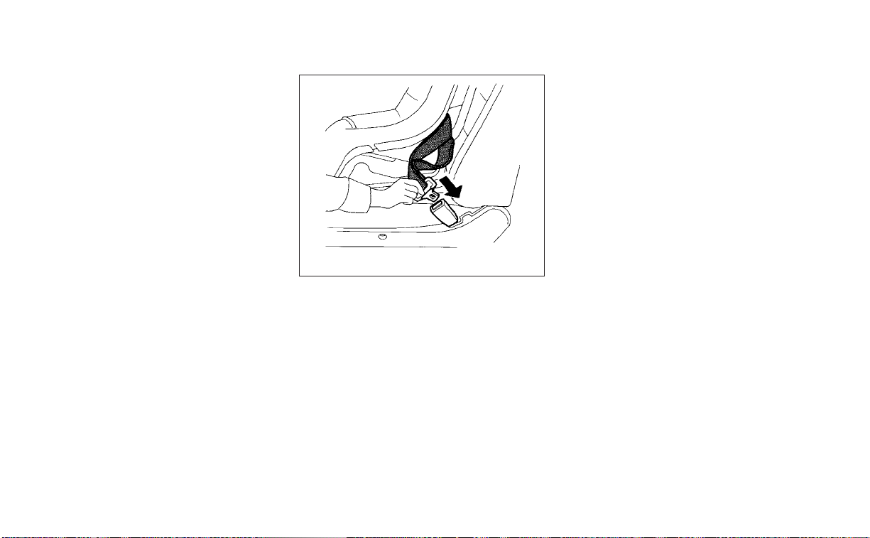
If the seating position does not have an
adjustable head restraint/headrest and
it is interfering with the proper child re-
straint fit, try another seating position or
a different child restraint.
3. Route the seat belt tongue through the
child restraint and insert it into the
buckle until you hear and feel the latch
engage. Be sure to follow the child re-
straint manufacturer’s instructions for
belt routing.
If the child restraint is equipped with a
top tether strap, route the top tether
strap and secure the tether strap to the
tether anchor point (rear seat installa-
tion only). For additional information, see
“Installing top tether strap” (P. 1-42).
Do not install child restraints that require
the use of a top tether strap in seating
positions that do not have a top tether
anchor.
WRS0680
Forward-facing – step 3
Safety-Seats, seat belts and supplemental restraint system 1-39
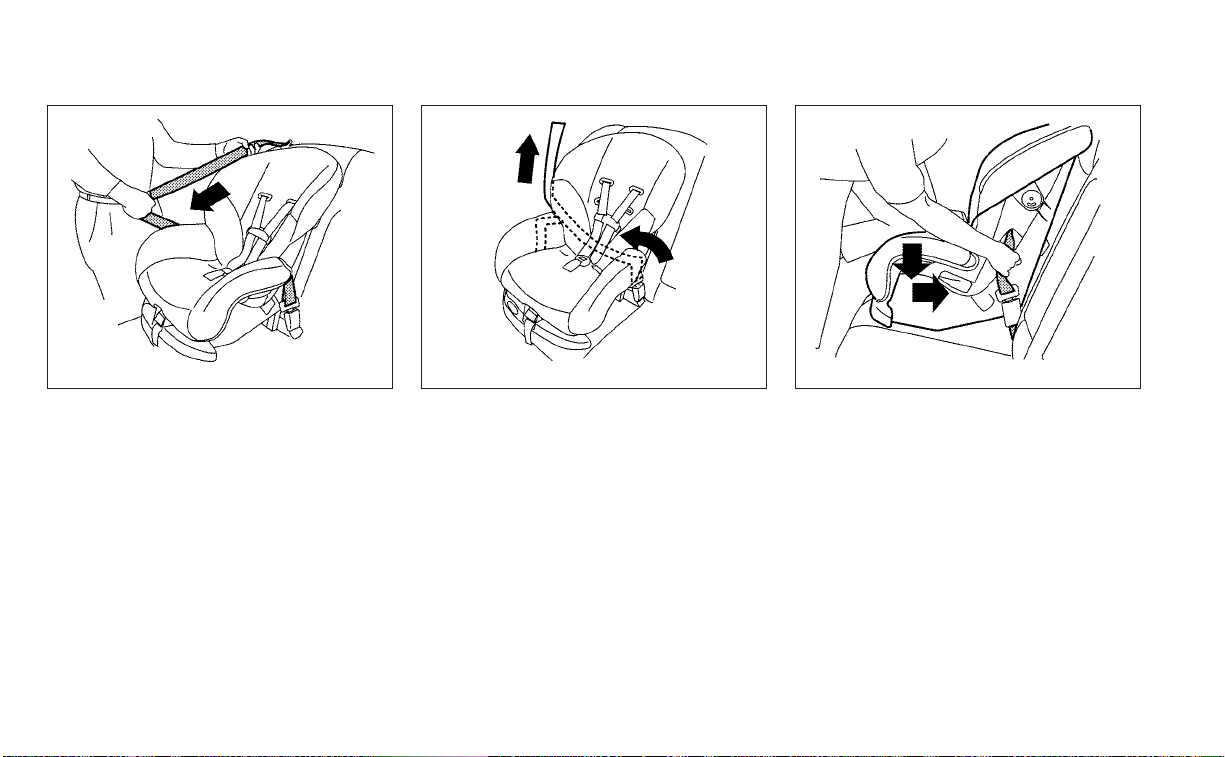
4. Pull the shoulder belt until the belt is fully
extended. At this time, the seat belt re-
tractor is in the ALR mode (child restraint
mode). It reverts to ELR mode when the
seat belt is fully retracted.
5. Allow the seat belt to retract. Pull up on
the shoulder belt to remove any slack in
the belt.
6. Remove any additional slack from the
seat belt; press downward and rear-
ward firmly in the center of the child re-
straint with your knee to compress the
vehicle seat cushion and seatback while
pulling up on the seat belt.
7. Tighten the tether strap according to the
manufacturer's instructions to remove
any slack.
LRS0667
Forward-facing – step 4
LRS0668
Forward-facing – step 5
WRS0681
Forward-facing – step 6
1-40 Safety-Seats, seat belts and supplemental restraint system
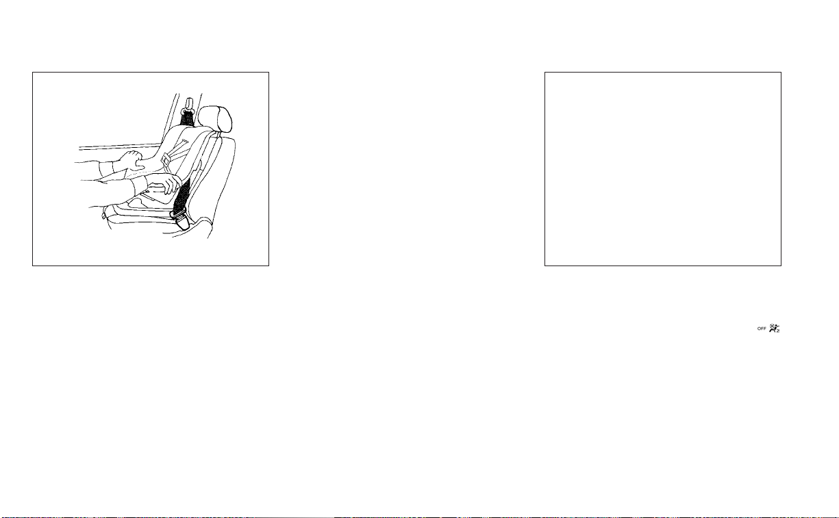
8. After attaching the child restraint, test it
before you place the child in it. Push it
from side to side while holding the child
restraint near the seat belt path. The
child restraint should not move more
than 1 inch (25 mm), from side to side. Try
to tug it forward and check to see if the
belt holds the restraint in place. If the
restraint is not secure, tighten the seat
belt as necessary, or put the restraint in
another seat and test it again. You may
need to try a different child restraint. Not
all child restraints fit in all types of
vehicles.
9. Check to make sure the child restraint is
properly secured prior to each use. If the
seat belt is not locked, repeat steps 4
through 8.
10. If the child restraint is installed in the
front passenger seat, place the ignition
switch in the ON position. The front
passenger air bag status light
should illuminate. If this light is not illu-
minated, see “Front passenger air bag
and status light” (P. 1-57). Move the child
restraint to another seating position.
Have the system checked. It is recom-
mended that you visit a NISSAN dealer
for this service.
After the child restraint is removed and the
seat belt is fully retracted, the ALR mode
(child restraint mode) is canceled.
WRS0698
Forward-facing – step 8
LRS3091
Forward-facing – step 10
Safety-Seats, seat belts and supplemental restraint system 1-41

Installing top tether strap
The child restraint top tether strap must be
used when installing the child restraint with
seat belts.
First, secure the child restraint with the seat
belt.
Rear bench seat
OUTBOARD AND CENTER SEATING
POSITIONS
1. Position the top tether strap
O
1
over the
seatback.
2. Secure the tether strap to the tether an-
chor point
O
2
as shown.
3. Tighten the tether strap according to
the manufacturer’s instructions to re-
move any slack.
If you have any questions when install-
ing a top tether strap, it is recommended
that you visit a NISSAN dealer for this
service.
WARNING
Child restraint anchorages are de-
signed to withstand only those loads
imposed by correctly fitted child re-
straints. Under no circumstances are
they to be used to attach adult seat
belts, or other items or equipment to
the vehicle. Doing so could damage the
child restraint anchorages. The child
restraint will not be properly installed
using the damaged anchorage, and a
child could be seriously injured or killed
in a collision.
BOOSTER SEATS
For additional information on installing a
booster seat in your vehicle, follow the in-
structions outlined in this section.
Precautions on booster seats
WARNING
If a booster seat and seat belt are not
used properly, the risk of a child being
injured or killed in a sudden stop or col-
lision greatly increases:
– Make sure the shoulder portion of
the belt is away from the child's face
and neck and the lap portion of the
belt does not cross the stomach.
– Make sure the shoulder belt is not
behind the child or under the child's
arm.
– A booster seat must only be installed
in a seating position that has a lap/
shoulder belt.
LRS3283
Rear seats
䊊
1
Top tether strap
䊊
2
Anchor point
1-42 Safety-Seats, seat belts and supplemental restraint system
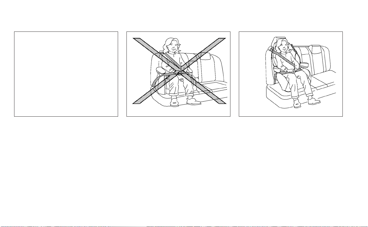
Booster seats of various sizes are offered
by several manufacturers. When selecting
any booster seat, keep the following points
in mind:
• Choose only a booster seat with a label
certifying that it complies with Federal
Motor Vehicle Safety Standard 213 or Ca-
nadian Motor Vehicle Safety Standard 213.
• Check the booster seat in your vehicle to
be sure it is compatible with the vehicle’s
seat and seat belt system.
• Make sure the child’s head will be properly
supported by the booster seat or vehicle
seat. The seatback must be at or above
the center of the child’s ears. For example,
if a low back booster seat is chosen, the
vehicle seatback must be at or above the
center of the child’s ears. If the seatback is
lower than the center of the child’s ears, a
high back booster seat should be used.
• If the booster seat is compatible with
your vehicle, place the child in the booster
seat and check the various adjustments
to be sure the booster seat is compatible
with the child. Always follow all recom-
mended procedures.
LRS2479
A. Low back booster seat
B. High back booster seat
LRS0453 LRS0464
Safety-Seats, seat belts and supplemental restraint system 1-43

All U.S. states and Canadian provinces or
territories require that infants and small
children be restrained in an approved
child restraint at all times while the ve-
hicle is being operated.
The instructions in this section apply to
booster seat installation in the rear seats
or the front passenger seat.
Booster seat installation
WARNING
All booster seats should be installed in
the rear seat. However, if you must in-
stall a booster seat in the front passen-
ger seat, move the passenger's seat to
the rearmost position.
To avoid injury to child, do not use the
lap/shoulder belt in the Automatic
Locking Retractor (ALR) mode when us-
ing a booster seat with the seat belts.
For additional information, see all Warnings
and Cautions in the “Child safety” (P. 1-21),
“Child restraints” (P. 1-23) and “Booster
seats” (P. 1-42) before installing a child
restraint.
Follow these steps to install a booster seat
in the rear seat or in the front passenger
seat:
1. If you must install a booster seat in the
front seat, move the seat to the rear-
most position.
2. Position the booster seat on the seat.
Only place it in a front-facing direction.
Always follow the booster seat manu-
facturer’s instructions.
WRS0699
1-44 Safety-Seats, seat belts and supplemental restraint system
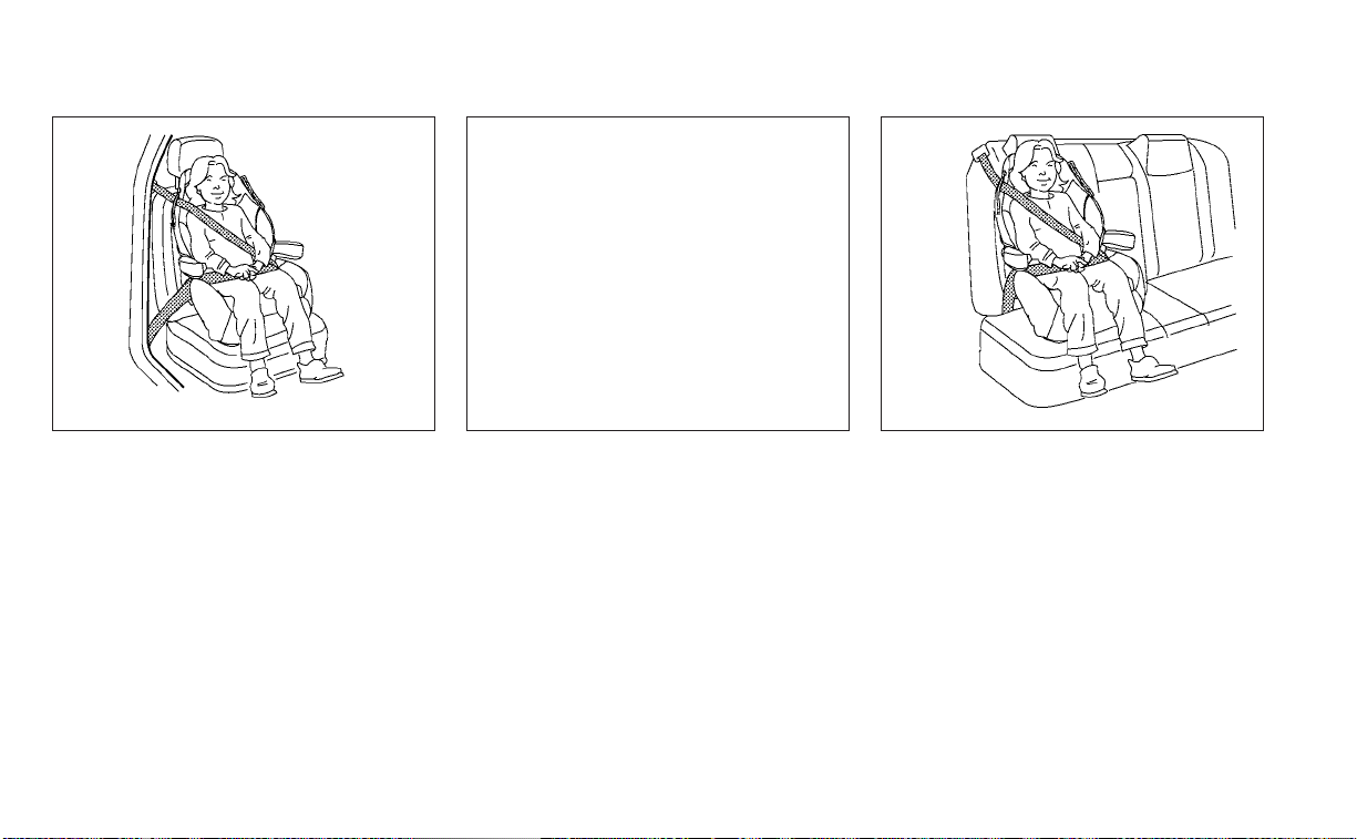
3. The booster seat should be positioned
on the vehicle seat so that it is stable.
If necessary, adjust or remove the head
restraint/headrest to obtain the correct
high back booster seat fit. If the head
restraint/headrest is removed, store it in
a secure place. Be sure to reinstall the
head restraint/headrest when the
booster seat is removed. For additional
information about head restraint/
headrest adjustment, removal and in-
stallation, see "Head restraints/
headrests" (P. 1-7).
LRS0454
Front passenger position
LRS0451
Rear center position
LRS0452
Rear outboard position
Safety-Seats, seat belts and supplemental restraint system 1-45

If the seating position does not have an
adjustable head restraint/headrest and
it is interfering with the proper booster
seat fit, try another seating position or a
different booster seat.
4. Position the lap portion of the seat belt
low and snug on the child’s hips. Be sure
to follow the booster seat manufactur-
er’s instructions for adjusting the seat
belt routing.
5. Pull the shoulder belt portion of the seat
belt toward the retractor to take up ex-
tra slack. Be sure the shoulder belt is
positioned across the top, middle por-
tion of the child’s shoulder. Be sure to
follow the booster seat manufacturer’s
instructions for adjusting the seat belt
routing.
6. Follow the warnings, cautions and in-
structions for properly fastening a seat
belt shown in “Three-point type seat belt
with retractor” (P. 1-15).
7. If the booster seat is installed in the front
passenger seat, place the ignition switch
in the ON position. The front passenger
air bag status light
may or may not
illuminate, depending on the size of the
child and the type of booster seat being
used. For additional information, see
“Front passenger air bag and status
light” (P. 1-57).
PRECAUTIONS ON SRS
This SRS section contains important infor-
mation concerning the following systems:
• Driver and front passenger supplemental
front-impact air bag (NISSAN Advanced
Air Bag System)
• Front seat-mounted side-impact supple-
mental air bag
• Rear outboard seat-mounted side-
impact supplemental air bag
• Roof-mounted curtain side-impact and
rollover supplemental air bag
• Driver and passenger supplemental knee
air bag
• Seat belt with pretensioner(s) (front and
rear outboard seats)
Supplemental front-impact air bag
system
The NISSAN Advanced Air Bag System can
help cushion the impact force to the head
and chest of the driver and front passenger
in certain frontal collisions.
LRS3091
SUPPLEMENTAL RESTRAINT SYSTEM
(SRS)
1-46 Safety-Seats, seat belts and supplemental restraint system

Front seat-mounted side-impact
supplemental air bag system
This system can help cushion the impact
force to the chest area of the driver and
front passenger in certain side-impact col-
lisions. The side air bags are designed to
inflate on the side where the vehicle is
impacted.
Rear outboard seat-mounted side-
impact supplemental air bag system
This system can help cushion the impact
force to the chest area of the rear outboard
seat passengers in certain side-impact
collisions. The side air bags are designed to
inflate on the side where the vehicle is
impacted.
Roof-mounted curtain side-impact and
rollover supplemental air bag system
This system can help cushion the impact
force to the head of occupants in front and
rear outboard seating positions in certain
side-impact collisions. The curtain air bags
are designed to inflate on the side where
the vehicle is impacted. In a rollover, the
curtain air bags are designed to inflate and
remain inflated for a short time.
Driver and passenger supplemental
knee air bags
This system can help cushion the impact
force to the driver’s and front passenger’s
knees in certain collisions.
The SRS is designed to supplement the
crash protection provided by the driver and
front passenger and rear seat belts and is
not a substitute for them. Seat belts
should always be correctly worn and the
occupant seated a suitable distance away
from the steering wheel, instrument panel
and door finishers. For additional informa-
tion, see “Seat belts” (P. 1-12).
The supplemental air bags operate only
when the ignition switch is placed in the
ON position.
After placing the ignition switch in the
ON position, the supplemental air bag
warning light illuminates. The supple-
mental air bag warning light will turn off
after about 7 seconds if the system is
operational.
Safety-Seats, seat belts and supplemental restraint system 1-47
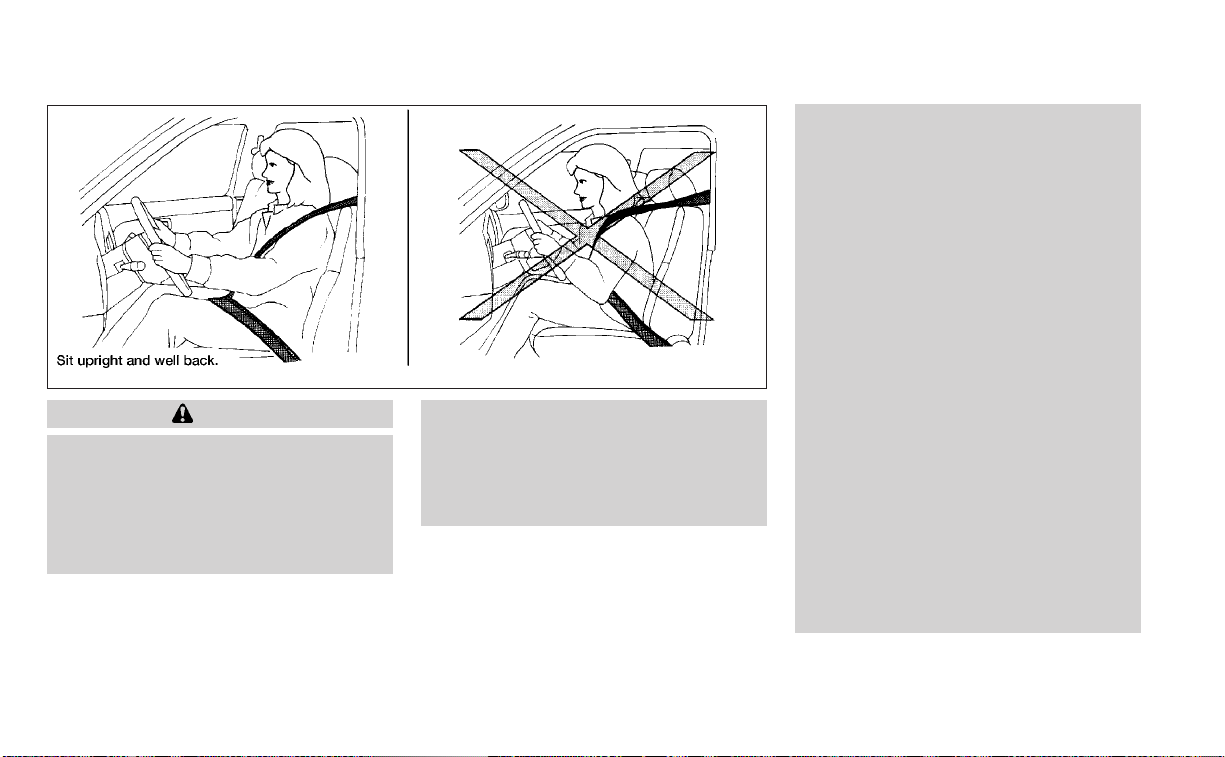
WARNING
• The front air bags ordinarily will not
inflate in the event of a side impact,
rear impact, rollover, or lower sever-
ity frontal collision. Always wear your
seat belts to help reduce the risk or
severity of injury in various kinds of
accidents
• The front passenger air bag and pas-
senger knee air bag will not inflate if
the passenger air bag status light is
lit. For additional information, see
“Front passenger air bag and status
light” (P. 1-57).
• The seat belts and the front air bags
are most effective when you are sit-
ting well back and upright in the seat.
The front air bags inflate with great
force. Even with the NISSAN Ad-
vanced Air Bag System, if you are un-
restrained, leaning forward, sitting
sideways or out of position in any
way, you are at greater risk of injury
or death in a crash. You may also re-
ceive serious or fatal injuries from
the front air bag if you are up against
it when it inflates. Always sit back
against the seatback and as far away
as practical from the steering wheel
or instrument panel. Always properly
use the seat belts.
• The driver and front passenger seat
belt buckles are equipped with sen-
sors that detect if the seat belts are
fastened. The NISSAN Advanced Air
Bag System monitors the severity of
a collision and seat belt usage, then
inflates the air bags as needed. Fail-
ure to properly wear seat belts can
increase the risk or severity of injury
in an accident.
WRS0031
1-48 Safety-Seats, seat belts and supplemental restraint system
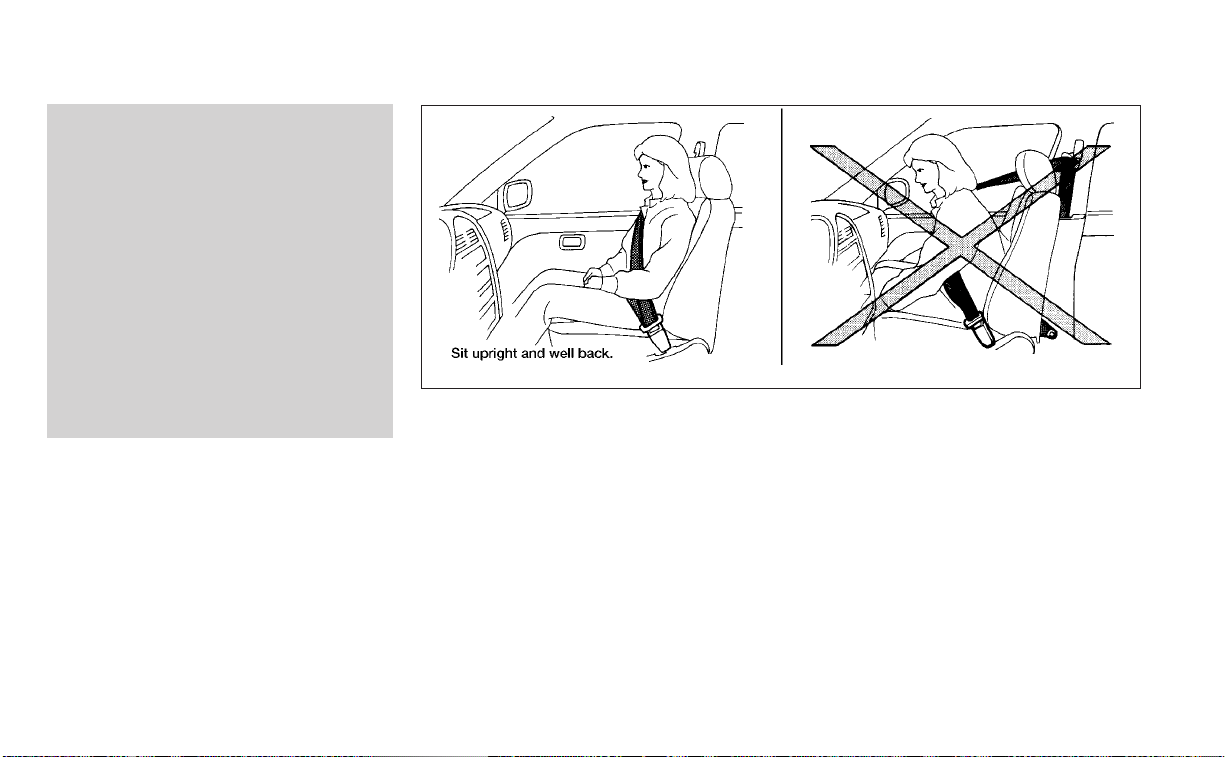
• The front passenger seat is equipped
with an occupant classification sen-
sor (weight sensor) that turns the
front passenger air bag and passen-
ger knee air bag OFF under some
conditions.This sensor is only used in
this seat. Failure to be properly
seated and wearing the seat belt can
increase the risk or severity of injury
in an accident. For additional infor-
mation, see “Front passenger air bag
and status light” (P. 1-57).
• Keep hands on the outside of the
steering wheel. Placing them inside
the steering wheel rim could increase
the risk that they are injured when
the front air bag inflates.
ARS1133
Safety-Seats, seat belts and supplemental restraint system 1-49
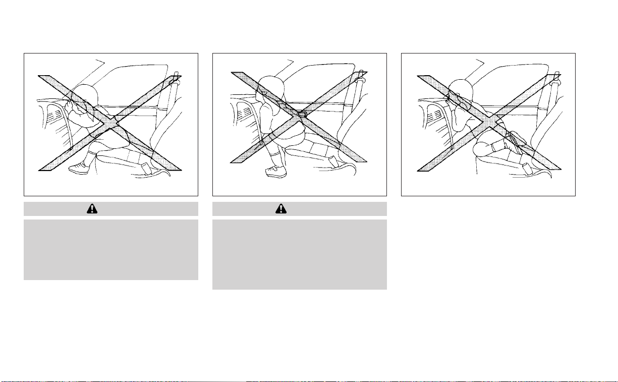
WARNING
• Never let children ride unrestrained
or extend their hands or face out of
the window. Do not attempt to hold
them in your lap or arms. Some ex-
amples of dangerous riding posi-
tions are shown in the illustrations.
WARNING
• Children may be severely injured or
killed when the front air bags, side air
bags or curtain air bags inflate if they
are not properly restrained. Pre-
teens and children should be prop-
erly restrained in the rear seat, if
possible.
ARS1041 ARS1042 ARS1043
1-50 Safety-Seats, seat belts and supplemental restraint system
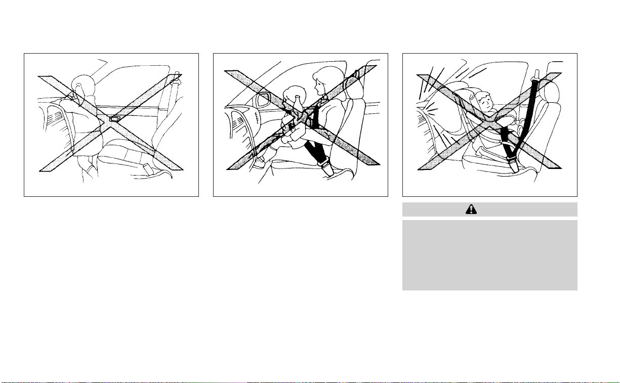
WARNING
• Even with the NISSAN Advanced Air
Bag System, never install a rear-
facing child restraint in the front seat.
An inflating front air bag could seri-
ously injure or kill your child. For ad-
ditional information, see “Child re-
straints” (P. 1-23).
ARS1044 ARS1045 ARS1046
Safety-Seats, seat belts and supplemental restraint system 1-51
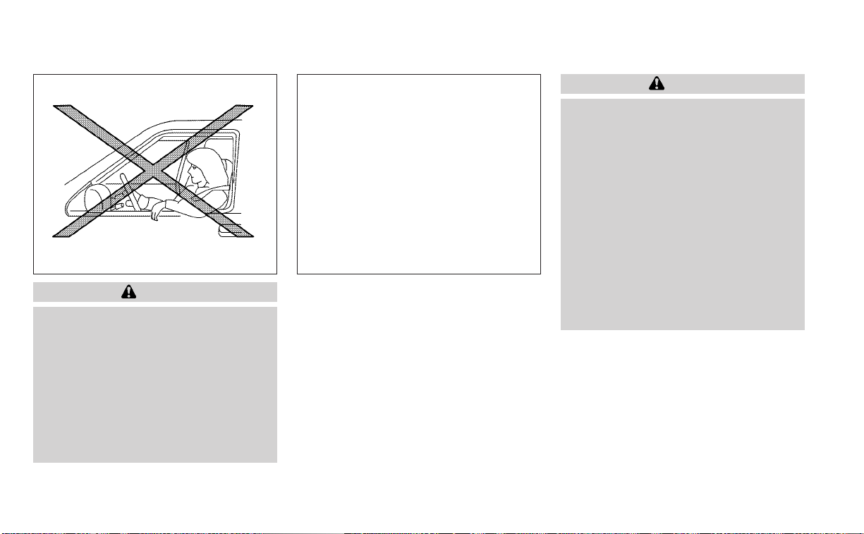
WARNING
Front and rear outboard seat-mounted
side-impact supplemental air bags and
roof-mounted curtain side-impact and
rollover supplemental air bags:
• The side air bags and curtain air bags
ordinarily will not inflate in the event
of a frontal impact, rear impact, or
lower severity side collision. Always
wear your seat belts to help reduce
the risk or severity of injury in various
kinds of accidents.
WARNING
• The seat belts, the side air bags and
curtain air bags are most effective
when you are sitting well back and
upright in the seat with both feet on
the floor. The side air bag and curtain
air bag inflate with great force. Do not
allow anyone to place their hand, leg
or face near the side air bag on the
side of the seatback of the front and
rear seat or near the side roof rails.
Do not allow anyone sitting in the
front seats or rear outboard seats to
extend their hand out of the window
or lean against the door. Some ex-
amples of dangerous riding posi-
tions are shown in the previous
illustrations.
WRS0431 LRS3119
1-52 Safety-Seats, seat belts and supplemental restraint system
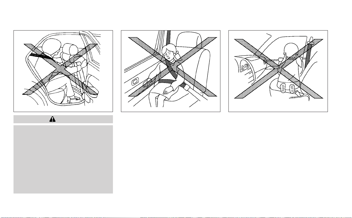
WARNING
• When sitting in the rear seat, do not
hold onto the seatback of the front
seat. If the side air bag inflates, you
may be seriously injured. Be espe-
cially careful with children, who
should always be properly re-
strained. Some examples of danger-
ous riding positions are shown in the
illustrations.
• Do not use seat covers on the front or
rear seatbacks. They may interfere
with side air bag inflation.
WRS0032 SSS0162 SSS0159
Safety-Seats, seat belts and supplemental restraint system 1-53

NISSAN Advanced Air Bag System
1. Top tether strap anchor
2. Roof-mounted curtain side-impact and
rollover supplemental air bag inflators
3. Rear seat belts
4. Roof-mounted curtain side-impact and
rollover supplemental air bag
5. Front seat-mounted side-impact
supplemental air bag
6. Head restraints/headrests
7. Front seat belts
8. Side-impact pressure sensor (driver's
side shown; front passenger's side
similar)
9. Supplemental front-impact air bags
10. Driver and passenger supplemental
knee air bags
11. Seats
12. Occupant classification sensor (weight
sensor)
13. Seat belt with pretensioner(s) (front
seats shown; rear outboard seats
similar)
14. Satellite sensors (passenger’s side
shown; driver’s side similar)
15. LATCH (Lower Anchors and Tethers for
CHildren) system
LRS3090
1-54 Safety-Seats, seat belts and supplemental restraint system

16. Satellite sensors (passenger ’s side
shown; driver’s side similar)
17. Rear outboard seat-mounted side-
impact supplemental air bags
WARNING
To ensure proper operation of the pas-
senger’s NISSAN Advanced Air Bag Sys-
tem, please observe the following
items.
• Do not allow a passenger in the rear
seat to push or pull on the seatback
pocket.
• Do not place heavy loads heavier
than 9.1 lbs. (4 kg) on the seatback,
head restraint/headrest or in the
seatback pocket.
• Make sure that there is nothing
pressing against the rear of the seat-
back, such as a child restraint in-
stalled in the rear seat or an object
stored on the floor.
• Make sure that there is no object
placed under the front passenger
seat.
• Make sure that there is no object
placed between the seat cushion and
center console or between the seat
cushion and the door.
• If a forward facing child restraint is
installed in the front passenger seat,
do not position the front passenger
seat so the child restraint contacts
the instrument panel. If the child re-
straint does contact the instrument
panel, the system may determine the
seat is occupied and the passenger
air bag and passenger knee air bag
may deploy in a collision. Also the
front passenger air bag status light
may not illuminate. For additional in-
formation about installing and using
child restraints, see "Child restraints"
(P. 1-23).
• Confirm the operating condition with
the front passenger air bag status
light.
• If you notice that the front passenger
air bag status light is not operating
as described in this section, get the
occupant classification system
checked. It is recommended that you
visit a NISSAN dealer for this service.
• Until you have confirmed with a
dealer that your passenger seat oc-
cupant classification system is work-
ing properly, position the occupants
in the rear seating positions.
• Do not position the front passenger
seat so it contacts the rear seat. If the
front seat does contact the rear seat,
the air bag system may determine a
sensor malfunction has occurred
and the front passenger air bag sta-
tus light may illuminate and the
supplemental air bag warning light
may flash.
This vehicle is equipped with the NISSAN
Advanced Air Bag System for the driver and
front passenger seats. This system is de-
signed to meet certification requirements
under U.S. regulations. It is also permitted in
Canada. However, all of the information,
cautions and warnings in this manual
still apply and must be followed.
The driver supplemental front-impact air
bag is located in the center of the steering
wheel. The front passenger supplemental
front-impact air bag is mounted in the
dashboard above the glove box. The front
air bags are designed to inflate in higher
severity frontal collisions, although they
may inflate if the forces in another type of
collision are similar to those of a higher
severity frontal impact. They may not in-
flate in certain frontal collisions. Vehicle
Safety-Seats, seat belts and supplemental restraint system 1-55

damage (or lack of it) is not always an indi-
cation of proper front air bag system
operation.
The NISSAN Advanced Air Bag System
monitors information from the crash zone
sensor, the Air bag Control Unit (ACU), seat
belt buckle sensors and occupant classifi-
cation sensor (weight sensor). Inflator op-
eration is based on the severity of a colli-
sion and seat belt usage for the driver. For
the front passenger, the occupant classifi-
cation sensor is also monitored. Based on
information from the sensor, only one front
air bag may inflate in a crash, depending on
the crash severity and whether the front
occupants are belted or unbelted. Addi-
tionally, the front passenger air bag and
passenger knee air bag may be automati-
cally turned off under some conditions, de-
pending on the weight detected on the
front passenger seat and how the seat belt
is used. If the front passenger air bag and
passenger knee air bag are OFF, the front
passenger air bag status light will be illumi-
nated. For additional information, see
“Front passenger air bag and status light”
(P. 1-57). One front air bag inflating does not
indicate improper performance of the
system.
If you have any questions about your air
bag system, it is recommended that you
visit a NISSAN dealer to obtain information
about the system. If you are considering
modification of your vehicle due to a dis-
ability, you may also contact NISSAN. Con-
tact information is contained in the front of
this Owner's Manual.
When a front air bag inflates, a fairly loud
noise may be heard, followed by the re-
lease of smoke. This smoke is not harmful
and does not indicate a fire. Care should be
taken to not inhale it, as it may cause irrita-
tion and choking. Those with a history of a
breathing condition should get fresh air
promptly.
Front air bags, along with the use of seat
belts, help to cushion the impact force on
the face and chest of the front occupants.
They can help save lives and reduce seri-
ous injuries. However, an inflating front air
bag may cause facial abrasions or other
injuries. Front air bags do not provide re-
straint to the lower body.
Even with NISSAN Advanced Air Bags, seat
belts should be correctly worn and the
driver and front passenger seated upright
as far as practical away from the steering
wheel or instrument panel. The front air
bags inflate quickly in order to help protect
the front occupants. Because of this, the
force of the front air bag inflating can in-
crease the risk of injury if the occupant is
too close to, or is against, the front air bag
module during inflation.
The front air bags deflate quickly after a
collision.
The front air bags operate only when the
ignition switch is placed in the ON
position.
After placing the ignition switch in the
ON position, the supplemental air bag
warning light illuminates. The supple-
mental air bag warning light will turn off
after about 7 seconds if the system is
operational.
1-56 Safety-Seats, seat belts and supplemental restraint system
Front passenger air bag and status
light
WARNING
The front passenger air bag and pas-
senger knee air bag are designed to au-
tomatically turn OFF under some con-
ditions. Read this section carefully to
learn how it operates. Proper use of the
seat, seat belt, and child restraints is
necessary for most effective protec-
tion. Failure to follow all instructions in
this manual concerning the use of
seats, seat belts, and child restraints
can increase the risk or severity of in-
jury in an accident.
Status light
The front passenger seat is equipped with
an occupant classification sensor (weight
sensor) that turns the front passenger air
bag and passenger knee air bag on or off
depending on the weight applied to the
front passenger seat. The status of the
front passenger air bag and passenger
knee air bag (ON or OFF) is indicated by the
front passenger air bag status light
which is located on the instrument panel.
After the ignition switch is placed in the
"ON" position, the front passenger air bag
status light on the instrument panel illumi-
nates for about 7 seconds and then turns
off or remains illuminated depending on
the front passenger seat occupied status.
The light operates as follows:
CONDITION DESCRIPTION
PASSENGER AIR BAG
STATUS LIGHT (
)
FRONT PASSENGER AIR BAG AND PASSENGER KNEE AIR BAG STATUS
Empty Empty front passenger seat ON (illuminated) INHIBITED
Nobody/Somebody
Bag or Child or Child Restraint or
Small Adult in front passenger
seat
ON (illuminated) INHIBITED
Adult Adult in the front passenger seat OFF (dark) ACTIVATED
In addition to the above, certain objects
placed on the front passenger seat may
also cause the light to operate as de-
scribed above depending on their weight.
For additional information, see “Normal op-
eration” (P. 1-59) and “Troubleshooting”
(P. 1-60).
LRS3091
Safety-Seats, seat belts and supplemental restraint system 1-57

Front passenger air bag
The front passenger air bag and passen-
ger knee air bag is designed to automati-
cally turn OFF when the vehicle is operated
under some conditions as described be-
low in accordance with U.S. regulations. If
the front passenger air bag and passenger
knee air bag is OFF, it will not inflate in a
crash. The driver air bag and other air bags
in your vehicle are not part of this system.
The purpose of the regulation is to help
reduce the risk of injury or death from an
inflating air bag to certain front passenger
seat occupants, such as children, by requir-
ing the air bags to be automatically turned
OFF. Certain sensors are used to meet the
requirements.
The occupant classification sensor in this
vehicle is a weight sensor. It is designed to
detect an occupant and objects on the
seat by weight. For example, if a child is in
the front passenger seat, the NISSAN Ad-
vanced Air Bag System is designed to turn
the front passenger air bag and passenger
knee air bag OFF in accordance with the
regulations. Also, if a child restraint of the
type specified in the regulations is on the
seat, its weight and the child’s weight can
be detected and cause the air bag to turn
OFF.
Front passenger seat adult occupants who
are properly seated and using the seat belt
as outlined in this manual should not
cause the front passenger air bag and pas-
senger knee air bag to be automatically
turned OFF. For small adults it may be
turned OFF, however if the occupant takes
his/her weight off the seat cushion (for ex-
ample, by not sitting upright, by sitting on
an edge of the seat, or by otherwise being
out of position), this could cause the sensor
to turn the air bags OFF. Always be sure to
be seated and wearing the seat belt prop-
erly for the most effective protection by the
seat belt and supplemental air bag.
NISSAN recommends that pre-teens and
children be properly restrained in a rear
seat. NISSAN also recommends that ap-
propriate child restraints and booster
seats be properly installed in a rear seat. If
this is not possible, the occupant classifica-
tion sensor is designed to operate as de-
scribed above to turn the front passenger
air bag and passenger knee air bag OFF for
specified child restraints as required by the
regulations. Failing to properly secure child
restraints and to use the ALR mode may
allow the restraint to tip or move in a colli-
sion or sudden stop. This can also result in
the passenger air bag and passenger knee
air bag inflating in a crash instead of being
OFF. For additional information about
proper use and installation, see “Child re-
straints” (P. 1-23).
If the front passenger seat is not occupied,
the front passenger air bag and passenger
knee air bag are designed not to inflate in a
crash. However, heavy objects placed on
the seat could result in air bag inflation,
because of the object’s weight detected by
the occupant classification sensor. Other
conditions could also result in air bag infla-
tion, such as if a child is standing on the
seat, or if two children are on the seat, con-
trary to the instructions in this manual. Al-
ways be sure that you and all vehicle occu-
pants are seated and restrained properly.
Using the front passenger air bag status
light, you can monitor when the front pas-
senger air bag and passenger knee air bag
are automatically turned OFF.
If an adult occupant is in the seat but the
front passenger air bag status light is illu-
minated (indicating that the front passen-
ger air bag and passenger knee air bag are
OFF), it could be that the person is a small
adult, or is not sitting on the seat properly
or not using the seat belt properly.
If a child restraint must be used in the front
seat, the front passenger air bag status
1-58 Safety-Seats, seat belts and supplemental restraint system

light may or may not be illuminated, de-
pending on the size of the child and the
type of child restraint being used. If the air
bag status light is not illuminated (indicat-
ing that the air bag might inflate in a crash),
it could be that the child restraint or seat
belt is not being used properly. Make sure
that the child restraint is installed properly,
the seat belt is used properly and the occu-
pant is positioned properly. If the air bag
status light is still not illuminated, reposi-
tion the occupant or child restraint in a rear
seat.
If the front passenger air bag status light
will not illuminate even though you believe
that the child restraint, the seat belts and
the occupant are properly positioned, it is
recommended that you take your vehicle
to a NISSAN dealer. A NISSAN dealer can
check system status by using a special
tool. However, until you have confirmed
with a dealer that your air bag is working
properly, reposition the occupant or child
restraint in a rear seat.
The NISSAN Advanced Air Bag System and
front passenger air bag status light will
take a few seconds to register a change in
the front passenger seat status. This is nor-
mal system operation and does not indi-
cate a malfunction.
If a malfunction occurs in the front passen-
ger air bag system, the supplemental air
bag warning light
, located in the me-
ter and gauges area of the instrument
panel, will be illuminated (blinking or
steadily lit). Have the system checked. It is
recommended that you visit a NISSAN
dealer for this service.
Normal operation
In order for the occupant classification
sensor system to classify the front passen-
ger based on weight, please follow the pre-
cautions and steps outlined below:
Precautions
• Make sure that there are no objects
weighing over 9.1 lbs. (4 kg) hanging on
the seat or placed in the seatback pocket.
• Make sure that a child restraint or other
object is not pressing against the rear of
the seatback.
• Make sure that a rear passenger is not
pushing or pulling on the back of the front
passenger seat.
• Make sure that the front passenger seat
or seatback is not forced back against an
object on the seat or floor behind it.
• Make sure that there is no object placed
under the front passenger seat.
Steps
1. Adjust the seat as outlined in the “Seats”
(P. 1-2) section of this manual. Sit upright,
leaning against the seatback, and cen-
tered on the seat cushion with your feet
comfortably extended to the floor.
2. Make sure there are no objects on your
lap.
3. Fasten the seat belt as outlined in the
“Seat belts” (P. 1-12) section of this
manual. Front passenger seat belt
buckle status is monitored by the occu-
pant classification system, and is used
as an input to determine occupancy
status. So, it is highly recommended that
the front passenger fasten their seat
belt.
4. Remain in this position for 30 seconds
allowing the system to classify the front
passenger before the vehicle is put into
motion.
5. Ensure proper classification by checking
the front passenger air bag status light.
Safety-Seats, seat belts and supplemental restraint system 1-59

NOTE:
This vehicle’s occupant classification
sensor system generally keeps the clas-
sification locked during driving, so it is
important that you confirm that the
front passenger is properly classified
prior to driving. However, the occupant
classification sensor may recalculate the
weight of the occupant under some con-
ditions (both while driving and when
stopped), so front passenger seat occu-
pants should continue to remain seated
as outlined above.
Troubleshooting
If you think the front passenger air bag
status light is incorrect:
1. If the light is ON with an adult occupying
the front passenger seat:
• Occupant is a small adult — the air bag
light is functioning as intended. The front
passenger air bag and passenger knee
air bag are suppressed.
However, if the occupant is not a small
adult, then this may be due to the following
conditions that may be interfering with the
weight sensors:
• Occupant is not sitting upright, leaning
against the seatback, and centered on
the seat cushion with his/her feet com-
fortably extended to the floor.
• A child restraint or other object pressing
against the rear of the seatback.
• A rear passenger pushing or pulling on
the back of the front passenger seat.
•
Forcing the front seat or seatback against
an object on the seat or floor behind it.
• An object placed under the front passen-
ger seat.
• An object placed between the seat cush-
ion and center console or between the
seat cushion and the door.
If the vehicle is moving, please come to a
stop when it is safe to do so. Check and
correct any of the above conditions. Re-
start the vehicle and wait 1 minute.
NOTE:
A system check will be performed during
which the front passenger air bag status
light will remain lit for about 7 seconds
initially.
If the light is still ON after this, the person
should be advised not to ride in the front
passenger seat and the vehicle should be
checked as soon as possible. It is recom-
mended that you visit a NISSAN dealer for
this service.
2. If the light is OFF with a small adult, child
or child restraint occupying the front
passenger seat.
This may be due to the following condi-
tions that may be interfering with the
weight sensors:
• Small adult or child is not sitting upright,
leaning against the seatback, and cen-
tered on the seat cushion with his/her
feet comfortably extended to the floor.
• The child restraint is not properly in-
stalled, as outlined in the “Child restraints”
section of this manual.
• An object weighing over 9.1 lbs. (4 kg)
hanging on the seat or placed in the seat-
back pocket.
• A child restraint or other object pressing
against the rear of the seatback.
• A rear passenger pushing or pulling on
the back of the front passenger seat.
• Forcing the front seat or seatback
against an object on the seat or floor be-
hind it.
1-60 Safety-Seats, seat belts and supplemental restraint system

• An object placed under the front passen-
ger seat.
• An object placed between the seat cush-
ion and center console.
If the vehicle is moving, please come to a
stop when it is safe to do so. Check and
correct any of the above conditions. Re-
start the vehicle and wait 1 minute.
NOTE:
A system check will be performed during
which the front passenger air bag status
light will remain lit for about 7 seconds
initially.
If the light is still OFF after this, the small
adult, child or child restraint should be re-
positioned in the rear seat and the vehicle
should be checked as soon as possible. It is
recommended that you visit a NISSAN
dealer for this service.
3. If the light is OFF with no front passenger
and no objects on the front passenger
seat, the vehicle should be checked. It is
recommended that you visit a NISSAN
dealer as soon as possible.
Other supplemental front-impact air
bag precautions
WARNING
• Do not place any objects on the
steering wheel pad or on the instru-
ment panel. Also, do not place any
objects between any occupant and
the steering wheel or instrument
panel. Such objects may become
dangerous projectiles and cause in-
jury if the front air bags inflate.
• Immediately after inflation, several
front air bag system components will
be hot. Do not touch them; you may
severely burn yourself.
• No unauthorized changes should be
made to any components or wiring
of the supplemental air bag system.
This is to prevent accidental inflation
of the supplemental air bag or dam-
age to the supplemental air bag
system.
• Do not make unauthorized changes
to your vehicle's electrical system,
suspension system or front end
structure. This could affect proper
operation of the front air bag system.
• Tampering with the front air bag sys-
tem may result in serious personal
injury. Tampering includes changes
to the steering wheel and the instru-
ment panel assembly by placing ma-
terial over the steering wheel pad
and above the instrument panel or
by installing additional trim material
around the air bag system.
• Removing or modifying the front
passenger seat may affect the func-
tion of the air bag system and result
in serious personal injury.
• Modifying or tampering with the
front passenger seat may result in
serious personal injury. For example,
do not change the front seats by
placing material on the seat cushion
or by installing additional trim mate-
rial, such as seat covers, on the seat
that are not specifically designed to
assure proper air bag operation. Ad-
ditionally, do not stow any objects
under the front passenger seat or the
seat cushion and seatback. Such ob-
jects may interfere with the proper
operation of the occupant classifica-
tion sensor (weight sensor).
Safety-Seats, seat belts and supplemental restraint system 1-61

• No unauthorized changes should be
made to any components or wiring
of the seat belt system. This may af-
fect the front air bag system. Tam-
pering with the seat belt system may
result in serious personal injury.
• It is recommended that you visit a
NISSAN dealer for work on and
around the front air bag system. It is
also recommended that you visit a
NISSAN dealer for installation of elec-
trical equipment. The Supplemental
Restraint System (SRS) wiring har-
nesses* should not be modified or
disconnected. Unauthorized electri-
cal test equipment and probing de-
vices should not be used on the air
bag system.
• A cracked windshield should be re-
placed immediately by a qualified re-
pair facility. A cracked windshield
could affect the function of the
supplemental air bag system.
*The SRS wiring harness connectors are
yellow and orange for easy identification.
When selling your vehicle, we request that
you inform the buyer about the front air
bag system and guide the buyer to the
appropriate sections in this Owner's
Manual.
Front and rear outboard
seat-mounted side-impact
supplemental air bag and
roof-mounted curtain
side-impact and rollover
supplemental air bag systems
The side air bags are located in the outside
of the seatback of the front and rear out-
board seats. The curtain air bags are lo-
cated in the side roof rails. All of the infor-
mation, cautions and warnings in this
manual must be followed. The side air
bags and curtain air bags are designed to
LRS3142
1-62 Safety-Seats, seat belts and supplemental restraint system

inflate in higher severity side collisions, al-
though they may inflate if the forces in an-
other type of collision are similar to those of
a higher severity impact. They are de-
signed to inflate on the side where the ve-
hicle is impacted. They may not inflate in
certain side collisions.
Curtain air bags are also designed to inflate
in certain types of rollover collisions or near
rollovers. As a result, certain vehicle move-
ments (for example, during severe off-
roading) may cause the curtain air bags to
inflate.
Vehicle damage (or lack of it) is not always
an indication of proper side air bag and
curtain air bag operation.
When the side air bags and curtain air bags
inflate, a fairly loud noise may be heard,
followed by the release of smoke. This
smoke is not harmful and does not indi-
cate a fire. Care should be taken not to
inhale it, as it may cause irritation and
choking. Those with a history of a breath-
ing condition should get fresh air promptly.
Side air bags, along with the use of seat
belts, help to cushion the impact force on
the chest and pelvic area of the front and
rear outboard occupants. Curtain air bags
help to cushion the impact force to the
head of occupants in the front and rear
outboard seating positions. They can help
save lives and reduce serious injuries. How-
ever, an inflating side air bag and curtain air
bag may cause abrasions or other injuries.
Side air bags and curtain air bags do not
provide restraint to the lower body.
The seat belts should be correctly worn
and the driver, front passenger and rear
outboard occupants seated upright as far
as practical away from the side air bag.
Rear seat passengers should be seated as
far away as practical from the door finish-
ers and side roof rails. The side air bags and
curtain air bags inflate quickly in order to
help protect the occupants. Because of
this, the force of the side air bag and curtain
air bag inflating can increase the risk of
injury if the occupant is too close to, or is
against, these air bag modules during in-
flation. The side air bag will deflate quickly
after the collision is over.
The curtain air bag will remain inflated for a
short time.
The side air bags and curtain air bags
operate only when the ignition switch is
placed in the ON position.
After placing the ignition switch in the
ON position, the supplemental air bag
warning light illuminates. The supple-
mental air bag warning light will turn off
after about 7 seconds if the system is
operational.
WARNING
• Do not place any objects near the
seatback of the front and rear seats.
Also, do not place any objects (an
umbrella,bag, etc.) between the front
and rear door finisher and the front
and rear seat. Such objects may be-
come dangerous projectiles and
cause injury if a side air bag inflate.
• Right after inflation, several side air
bag and curtain air bag system com-
ponents will be hot. Do not touch
them; you may severely burn
yourself.
• No unauthorized changes should be
made to any components or wiring
of the side air bag and curtain air bag
systems. This is to prevent damage
to or accidental inflation of the side
air bag and curtain air bag or dam-
age to the side air bag and curtain air
bag systems.
Safety-Seats, seat belts and supplemental restraint system 1-63

• Do not make unauthorized changes
to your vehicle's electrical system,
suspension system or side panel.
This could affect proper operation of
the side air bag and cur tain air bag
systems.
• Tampering with the side air bag sys-
tem may result in serious personal
injury. For example, do not change
the front and rear seats by placing
material near the seatbacks or by in-
stalling additional trim material,
such as seat covers, around the side
air bag.
• It is recommended that you visit a
NISSAN dealer for work on and
around the side air bag and curtain
air bag. It is also recommended that
you visit a NISSAN dealer for installa-
tion of electrical equipment. The SRS
wiring harnesses* should not be
modified or disconnected. Unauthor-
ized electrical test equipment and
probing devices should not be used
on the side air bag or cur tain air bag
system.
* The SRS wiring harness connectors are
yellow and orange for easy identification.
When selling your vehicle, we request that
you inform the buyer about the side air bag
and curtain air bag systems and guide the
buyer to the appropriate sections in this
Owner's Manual.
Driver and front passenger
supplemental knee air bag
The knee air bag is located in the knee
bolster, on the driver’s and passenger’s
side. All of the information, cautions and
warnings in this manual apply and must
be followed. The knee air bag is designed
to inflate in higher severity frontal collisions,
although it may inflate if the forces in an-
other type of collision are similar to those of
a higher severity frontal impact. It may not
inflate in certain collisions.
LRS3276
Driver’s side
1-64 Safety-Seats, seat belts and supplemental restraint system

Vehicle damage (or lack of it) is not always
an indication of proper knee air bag
operation.
When the knee air bag inflates, a fairly loud
noise may be heard, followed by release of
smoke. This smoke is not harmful and
does not indicate a fire. Care should be
taken not to inhale it, as it may cause irrita-
tion and choking. Those with a history of a
breathing condition should get fresh air
promptly.
The knee air bag helps to cushion the im-
pact force on the knees of the driver and
passenger. It can help reduce serious inju-
ries. However, an inflating knee air bag may
cause abrasions or other injuries. The knee
air bag provides restraint to the lower body.
The knee air bag inflates quickly in order to
help protect the occupants. Because of
this, the force of the knee air bag inflating
can increase the risk of injury if the occu-
pant is too close to, or is against, this air bag
module during inflation. The knee air bag
will deflate quickly after the collision is over
OR the knee air bag will remain inflated for
a short time.
The knee air bag operates only when the
ignition switch is placed in the ON
position.
After placing the ignition switch in the
ON position, the supplemental air bag
warning light illuminates. The supple-
mental air bag warning light will turn off
after about 7 seconds if the system is
operational.
WARNING
• Do not place any objects between the
knee bolster and the driver’s or pas-
senger’s seat. Such objects may be-
come dangerous projectiles and
cause injury if a knee air bag inflates.
• Right after inflation, the knee air bag
system components will be hot. Do
not touch them; you may severely
burn yourself.
• No unauthorized changes should be
made to any components or wiring
of the knee air bag system. This is to
prevent damage to or accidental in-
flation of the knee air bag system.
• Do not make unauthorized changes
to your vehicle's electrical system or
suspension system. This could affect
proper operation of the knee air bag
system.
• Tampering with the knee air bag sys-
tem may result in serious personal
injury. For example, do not change
the driver or passenger knee bolster
or install additional trim material
around the knee air bag.
LRS3290
Passenger’s side
Safety-Seats, seat belts and supplemental restraint system 1-65

• It is recommended that you visit a
NISSAN dealer for work on and
around the knee air bag. It is also rec-
ommended that you visit a NISSAN
dealer for installation of electrical
equipment. The SRS wiring har-
nesses* should not be modified or
disconnected. Unauthorized electri-
cal test equipment and probing de-
vices should not be used on the knee
air bag system.
*
The SRS wiring harness or connectors are
yellow or orange for easy identification.
When selling your vehicle, we request that
you inform the buyer about the knee air
bag system and guide the buyer to the
appropriate sections in this manual.
Seat belt with pretensioner(s)
(front and rear outboard seats)
WARNING
• The pretensioner(s) cannot be re-
used after activation. They must be
replaced together with the retractor
and buckle as a unit.
• If the vehicle becomes involved in a
collision but pretensioner(s) are not
activated, be sure to have the preten-
sioner system checked and, if neces-
sary, replaced. It is recommended
that you visit a NISSAN dealer for this
service.
• No unauthorized changes should be
made to any components or wiring
of the pretensioner system. This is to
prevent damage to or accidental ac-
tivation of the pretensioner(s). Tam-
pering with the pretensioner system
may result in serious personal injury.
• It is recommended that you visit a
NISSAN dealer for work on and
around the pretensioner system. It is
also recommended that you visit a
NISSAN dealer for installation of elec-
trical equipment. Unauthorized elec-
trical test equipment and probing
devices should not be used on the
pretensioner system.
• If you need to dispose of the preten-
sioner(s) or scrap the vehicle, it is rec-
ommended that you visit a NISSAN
dealer for this service. Incorrect dis-
posal procedures could cause per-
sonal injury.
The pretensioner system may activate
with the supplemental air bag system in
certain types of collisions. Working with the
seat belt retractor, the pretensioner(s) help
tighten the seat belt when the vehicle be-
comes involved in certain types of colli-
sions, helping to restrain front and rear out-
board seat occupants.
The pretensioner(s) are encased within the
seat belt retractor and to the seat belt an-
chor affixed to the floor of the vehicle.
These seat belts are used the same way as
conventional seat belts.
When pretensioner(s) activate, smoke is re-
leased and a loud noise may be heard. This
smoke is not harmful and does not indi-
cate a fire. Care should be taken not to
inhale it, as it may cause irritation and
choking. Those with a history of a breath-
ing condition should get fresh air promptly.
After the pretensioner(s’) activation, load
limiters allow the seat belt to release web-
bing (if necessary) to reduce forces against
the chest.
The supplemental air bag warning light
is used to indicate malfunctions in the
pretensioner system. For additional infor-
mation, see "Supplemental air bag warning
1-66 Safety-Seats, seat belts and supplemental restraint system
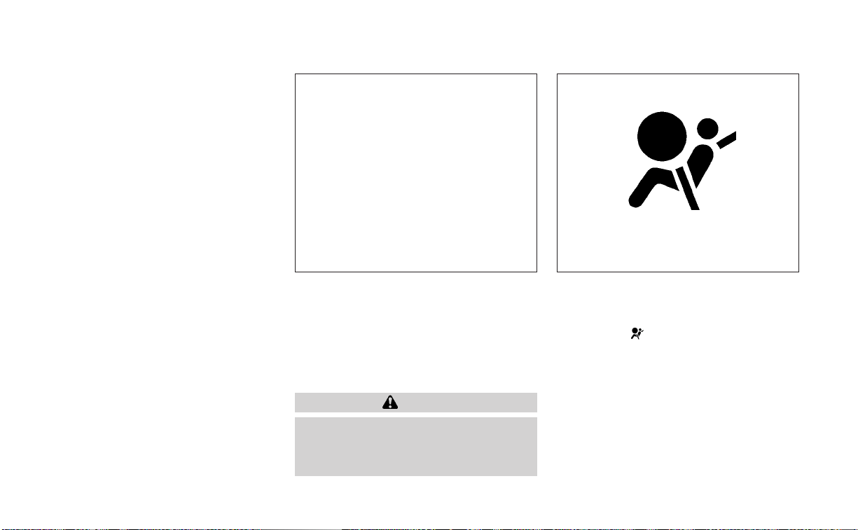
light" (P. 1-67). If the operation of the supple-
mental air bag warning light indicates
there is a malfunction, have the system
checked. It is recommended that you visit a
NISSAN dealer for this service.
When selling your vehicle, we request that
you inform the buyer about the preten-
sioner system and guide the buyer to the
appropriate sections in this Owner's
Manual.
SUPPLEMENTAL AIR BAG WARNING
LABELS
Warning labels about the supplemental
front-impact air bag system are placed in
the vehicle as shown in the illustration.
WARNING
Do not use a rear-facing child restraint
on a seat protected by an air bag in
front of it. If the air bag deploys, it may
cause serious injury or death.
SUPPLEMENTAL AIR BAG WARNING
LIGHT
The supplemental air bag warning light,
displaying
in the instrument panel,
monitors the circuits for the air bag sys-
tems, pretensioner(s) and all related wiring.
When the ignition switch is placed in the ON
position, the supplemental air bag warning
light illuminates for about 7 seconds and
then turns off. This means the system is
operational.
LRS2163
1. SRS air bag warning labels (located on
the sun visors)
LRS0100
Safety-Seats, seat belts and supplemental restraint system 1-67

If any of the following conditions occur, the
front air bag, side air bag, curtain air bag,
knee air bag and pretensioner systems
need servicing:
• The supplemental air bag warning light
remains on after approximately 7
seconds.
• The supplemental air bag warning light
flashes intermittently.
• The supplemental air bag warning light
does not come on at all.
Under these conditions, the front air bag,
side air bag, curtain air bag, knee air bag or
pretensioner systems may not operate
properly. They must be checked and re-
paired. It is recommended that you visit a
NISSAN dealer for this service.
WARNING
If the supplemental air bag warning
light is on, it could mean that the front
air bag, side air bag, curtain air bag,
knee air bag and/or pretensioner sys-
tems will not operate in an accident. To
help avoid injury to yourself or others,
have your vehicle checked as soon as
possible. It is recommended that you
visit a NISSAN dealer for this service.
Repair and replacement
procedure
The front air bags, side air bags, curtain air
bags, knee air bags and pretensioner(s) are
designed to inflate on a one-time-only ba-
sis. As a reminder, unless it is damaged, the
supplemental air bag warning light re-
mains illuminated after inflation has oc-
curred. These systems should be repaired
and/or replaced as soon as possible. It is
recommended that you visit a NISSAN
dealer for this service.
When maintenance work is required on the
vehicle, the front air bags, side air bags,
curtain air bags, knee air bags, pretension-
er(s) and related parts should be pointed
out to the person performing the mainte-
nance. The ignition switch should always
be placed in the LOCK position when work-
ing under the hood or inside the vehicle.
WARNING
• Once a front air bag, side air bag, cur-
tain air bag or knee air bag has in-
flated, the air bag module will not
function again and must be replaced.
Additionally, the activated preten-
sioner(s) must also be replaced. The
air bag module and pretensioner(s)
should be replaced. It is recom-
mended that you visit a NISSAN
dealer for this service. However, the
air bag module and pretensioner(s)
cannot be repaired.
• The front air bag, side air bag, curtain
air bag, knee air bag systems and the
pretensioner system should be in-
spected if there is any damage to the
front end or side portion of the ve-
hicle. It is recommended that you
visit a NISSAN dealer for this service.
• If you need to dispose of the supple-
mental air bag or pretensioner sys-
tems or scrap the vehicle, it is recom-
mended that you contact a NISSAN
dealer for this service. Incorrect dis-
posal procedures could cause per-
sonal injury.
1-68 Safety-Seats, seat belts and supplemental restraint system

• If there is an impact to your vehicle
from any direction, your Occupant
Classification Sensor (OCS) should be
checked to verify it is still functioning
correctly. It is recommended that you
visit a NISSAN dealer for this service.
The OCS should be checked even if no
air bags deploy as a result of the im-
pact. Failure to verify proper OCS
function may result in an improper
air bag deployment resulting in in-
jury or death.
Safety-Seats, seat belts and supplemental restraint system 1-69

2 Instruments and controls
Instrument panel................................2-2
Meters and gauges .............................2-4
Speedometer and odometer .................2-4
Tachometer ..................................2-6
Engine coolant temperature gauge ..........2-6
Fuel gauge ...................................2-7
Distance To Empty (DTE) .....................2-7
Variable Compression Turbo (if so
equipped) ....................................2-8
Warning lights, indicator lights and audible
reminders .......................................2-9
Checking lights ..............................2-10
Warning/Indicator lights (red) ...............2-10
Warning/Indicator lights (yellow) ............2-12
Warning/Indicator lights (other) .............2-17
Audible reminders...........................2-18
Vehicle information display- 5 inch (13 cm)
Type A (if so equipped) .........................2-18
How to use the vehicle information
display ......................................2-19
Startup display ..............................2-19
Resetting the drive computer ...............2-20
Oil control system (if so equipped) ...........2-20
Settings .....................................2-21
Vehicle information display warnings
and indicators...............................2-27
Vehicle information display —7 inch (18 cm)
Type B (if so equipped) .........................2-33
How to use the vehicle information
display ......................................2-34
Startup display ..............................2-34
Resetting the drive computer ...............2-34
Oil control system (if so equipped) ...........2-35
Settings .....................................2-35
Vehicle information display warnings
and indicators...............................2-43
Security systems ...............................2-50
Vehicle security system .....................2-50
NISSAN Vehicle Immobilizer System .........2-52
Wiper and washer switch .......................2-53
Switch operation ............................2-53
Rear window and outside mirror
(if so equipped) defroster switch ...............2-54
Headlight and turn signal switch ...............2-55
Headlight control switch
....................2-55
LED
Day time Running Lights (DRL)
system (if so equipped) ......................2-60
Instrument brightness control ..............2-60
Turn signal switch ...........................2-61
Fog light switch (if so equipped) .............2-61
Horn ...........................................2-62

Heated seat switches (if so equipped) ..........2-62
Heated steering wheel switch (if so equipped) . . 2-63
Steering Assist switch (for vehicles with
ProPILOT Assist) (if so equipped) ................2-64
Emergency call (SOS) button (if so equipped) . . . 2-65
Rear Door Alert .................................2-65
Power outlet ...................................2-67
Ex tended storage switch .......................2-68
Storage ........................................2-69
Front-door pockets .........................2-69
Seatback pockets (if so equipped) ...........2-69
Glovebox ...................................2-70
Console box .................................2-70
Overhead sunglasses storage...............2-70
Cup holders ................................. 2-71
Windows .......................................2-72
Power windows .............................2-72
Moonroof (if so equipped) ......................2-75
Power moonroof ............................2-75
Interior lights ...................................2-76
Map lights ...................................2-77
Personal lights ..............................2-77
Trunk light ......................................2-78
HomeLink® Universal Transceiver
(if so equipped) .................................2-78
Programming HomeLink® ...................2-79
Programming HomeLink® for Canadian
customers and gate openers ...............2-80
Operating the HomeLink® Universal
Transceiver ..................................2-81
Programming trouble-diagnosis ............2-81
Clearing the programmed information ......2-81
Reprogramming a single HomeLink®
button ......................................2-82
If your vehicle is stolen ......................2-82

1. Vents (P. 4-30)
2.
Steering wheel switches for audio control*
Vehicle information display controls
(P. 2-18, 2-33)
3. Headlight/fog light (if so equipped)/
turn signal switch (P. 2-55)
Paddle shifters (if so equipped) (P. 5-18)
4. Driver supplemental air bag (P. 1-46)
Horn (P. 2-62)
5. Meters and gauges (P. 2-4)
Warning and indicator lights (P. 2-9)
Vehicle information display (P. 2-18,
2-33)
6. Wiper and washer switch (P. 2-53)
7. Heater and air conditioner (P. 4-32, 4-39)
Heated seat switches (if so equipped)
(P. 2-62)
Heated steering wheel switch
(if so equipped) (P. 2-63)
8. Navigation system* (if so equipped)
Audio system*
9. Front passenger supplemental air bag
(P. 1-46)
10. Front passenger supplemental knee
airbag (P. 1-46)
11.. Glove box (P. 2-69)
12. Front passenger air bag status light
(P. 1-46)
Hazard warning flasher switch (P. 6-2)
13. Power outlet (P. 2-67)
USB connection por t (if so equipped)
(P. 4-2, 4-66)
Aux jack*
14. Cup holders (P. 2-69)
15 Shift lever (P. 5-18)
LII2584
INSTRUMENT PANEL
2-2 Instruments and controls

16. Electronic parking brake switch
(if so equipped) (P. 5-24)
Automatic brake hold switch
(if so equipped) (P. 5-27)
17. Push-button ignition switch (P. 5-13)
18. Cruise control switches (if so equipped)
(P. 5-68)
Bluetooth® Hands-free Phone System*
ProPILOT Assist Switch (if so equipped)
(P. 5-70)
19. Driver supplemental knee airbag
(P. 1-46)
20. Hood release (P. 3-22)
Fuel-filler door release (P. 3-25)
Tilt/telescopic steering wheel controls
(P. 3-27)
21. Trip computer reset switch (P. 2-4)
Instrument brightness control (P. 2-55)
Steering assist switch (for vehicles with
ProPILOT Assist) (if so equipped)
(P. 2-64)
Trunk opener (P. 3-22)
*: For additional information, refer to the
separate NissanConnect® Owner's Manual.
Refer to the page number indicated in
parentheses for operating details.
Instruments and controls 2-3

1. Tachometer
2. Warning and indicator lights
3. Vehicle information display
4. Speedometer
5. Fuel gauge
6. Engine coolant temperature gauge
SPEEDOMETER AND ODOMETER
This vehicle is equipped with a speedom-
eter and odometer. The speedometer is
located on the right side of the meter clus-
ter. The odometer is located within the ve-
hicle information display.
Speedometer
The speedometer indicates vehicle speed.
LIC4199
LIC2255
5 inch (13 cm) Type A (if so equipped)
METERS AND GAUGES
2-4 Instruments and controls

Odometer/Twin trip odometer
The odometer and the twin trip odometer
O
1
are displayed in the vehicle information
display when the ignition switch is placed
in the ON position.
The odometer records the total distance
the vehicle has been driven.
The twin trip odometer records the dis-
tance of individual trips.
Changing the display
Push the TRIP RESET switch
O
2
on the left
side of the instrument panel to change the
display as follows:
Odometer Mileage → Trip
→ Trip
→ Odometer Mileage
Resetting the trip odometer
Push the TRIP RESET switch
O
2
until the
desired trip odometer (Trip
or Trip
) is displayed.
Pushing the TRIP RESET switch
O
2
for more
than 1 second resets the currently dis-
played trip odometer to zero.
LIC2218
7 inch (18 cm) Type B (if so equipped)
LIC4499
5 inch (13 cm) Type A (if so equipped)
LIC2921
7 inch (18 cm) Type B (if so equipped)
Instruments and controls 2-5

TACHOMETER
The tachometer indicates engine speed in
revolutions per minute (rpm).
Do not rev the engine into the red zone
O
1
.
CAUTION
When engine speed approaches the
red zone, shift to a higher gear or re-
duce engine speed. Operating the en-
gine in the red zone may cause serious
engine damage.
ENGINE COOLANT TEMPERATURE
GAUGE
The gauge indicates the engine coolant
temperature. The engine coolant tempera-
ture is within the normal range
O
1
when
the gauge needle points within the zone
shown in the illustration.
The engine coolant temperature varies
with the outside air temperature and driv-
ing conditions.
LIC4217
5 inch (13 cm) Type A (if so equipped)
LIC4641
7 inch (18 cm) Type B (if so equipped)
LIC4209
5 inch (13 cm) Type A (if so equipped)
2-6 Instruments and controls
CAUTION
If the gauge indicates coolant tem-
perature near the hot (H) end of the
normal range, reduce vehicle speed to
decrease temperature. If the gauge is
over the normal range, stop the vehicle
as soon as safely possible. If the engine
is overheated, continued operation of
the vehicle may seriously damage the
engine. For additional information, see
“If your vehicle overheats” (P. 6-13) for
immediate action required.
FUEL GAUGE
The gauge indicates the approximate fuel
level in the tank.
The gauge may move slightly during brak-
ing, turning, acceleration, or going up or
down hills.
The gauge needle returns to 0 (Empty) af-
ter the ignition switch is placed in the OFF
position.
The low fuel warning message shows in
the vehicle information display when the
amount of fuel in the tank is getting low.
Refill the fuel tank before the gauge reg-
isters 0 (Empty).
The
indicates that the fuel-filler door
is located on the driver's side of the vehicle.
CAUTION
• If the vehicle runs out of fuel, the
Malfunction Indicator Light (MIL) may
come on. Refuel as soon as possible.
After a few driving trips, the
light
should turn off. If the light remains on
after a few driving trips, have the ve-
hicle inspected. It is recommended
that you visit a NISSAN dealer for this
service.
• For additional information, see “Mal-
function Indicator Light (MIL)” (P. 2-15).
DISTANCE TO EMPTY (DTE)
Displays the estimated distance the ve-
hicle can be driven before refueling. The
value is calculated based on recent fuel
economy, the amount of fuel remaining in
the fuel tank, and the actual fuel
consumption.
LIC3538
7 inch (18 cm) Type B (if so equipped)
LIC2222
Instruments and controls 2-7

Changes in driving patterns or conditions
can cause the DTE value to vary. As a result,
the value displayed may differ from the ac-
tual distance that can be driven.
DTE display will change to “---” when the
fuel level in the tank is getting low, prior to
the fuel gauge reaching 0 (Empty).
NOTE:
• The DTE value after refill is estimated
based on recent fuel economy and
amount of fuel added.
• If a small amount of fuel is added, or
the ignition is on during refueling, the
display may not be updated.
• Conditions that affect the fuel
economy will also affect the estimated
DTE value (city/highway driving, idle
time, remote start time, terrain, sea-
sonal weather, added vehicle weight,
added deflectors, roof racks, etc.).
VARIABLE COMPRESSION TURBO
(if so equipped)
Your engine is equipped with a variable
compression ratio system called “Variable
Compression Turbo”. This system can vary
the engine compression ratio continuously.
According to driving conditions, the system
applies optimum compression ratio auto-
matically to achieve both high output and
high fuel economy efficiency.
This is not a physical gauge. It is a display
option in the vehicle information display
that can be selected. For additional infor-
mation, see “Vehicle information display”
(P. 2-33).
䊊
1
Compression ratio status display
Displays the status of compression ra-
tio controlled by Variable Compression
Turbo. The lowest compression ratio
(8:1) and the highest (14:1) are displayed
as “Power” and ”ECO” respectively.
䊊
2
Turbo charger boost pressure gauge
Displays the turbo charger boost
pressure.
NOTE:
Under some conditions, the compres-
sion ratio may not change. This is not a
malfunction of the system.
CAUTION
If the Variable Compression Turbo be-
comes faulty, the Malfunction Indicator
Light (MIL) may come on. For additional
information, see “Malfunction Indicator
Light (MIL)” (P. 2-15).
LIC4236
2-8 Instruments and controls
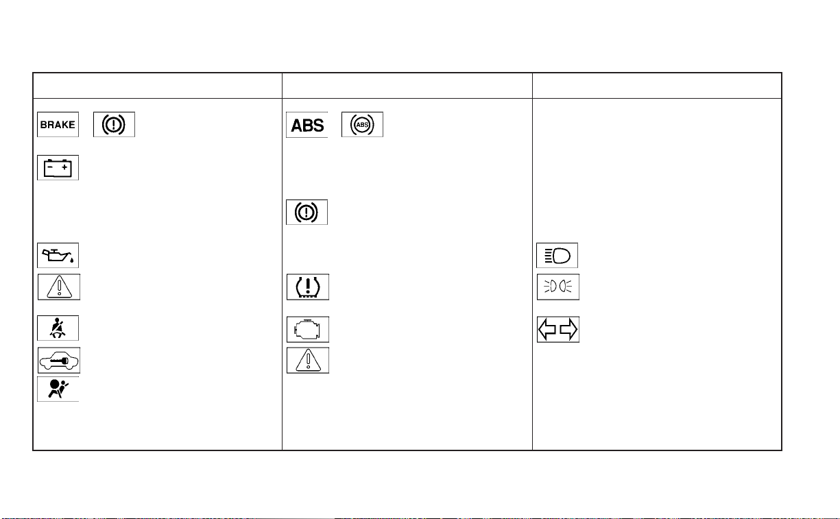
Warning/Indicator light (red) Warning/Indicator light (yellow) Warning/Indicator light (other)
or Brake warning light or Anti-lock Braking System (ABS)
warning light
Automatic brake hold indicator light
(white/green) (if so equipped)
Charge warning light Automatic Emergency Braking (AEB) with
Pedestrian Detection system warning light
Front fog light indicator light (green)
(if so equipped)
or Electronic parking brake
indicator light (if so equipped)
or Electronic parking brake
warning light (if so equipped)
High Beam Assist indicator light (green)
(if so equipped)
Engine oil pressure warning light Front passenger air bag status light High beam indicator light (blue)
Master warning light Low tire pressure warning light Side light and headlight indicator light
(green)
Seat belt warning light and chime Malfunction Indicator Light (MIL) Turn signal/hazard indicator lights (green)
Security indicator light Master warning light
Supplemental air bag warning light Power steering warning light
Rear Automatic Braking (RAB) warning light
(if so equipped)
WARNING LIGHTS, INDICATOR LIGHTS
AND AUDIBLE REMINDERS
Instruments and controls 2-9
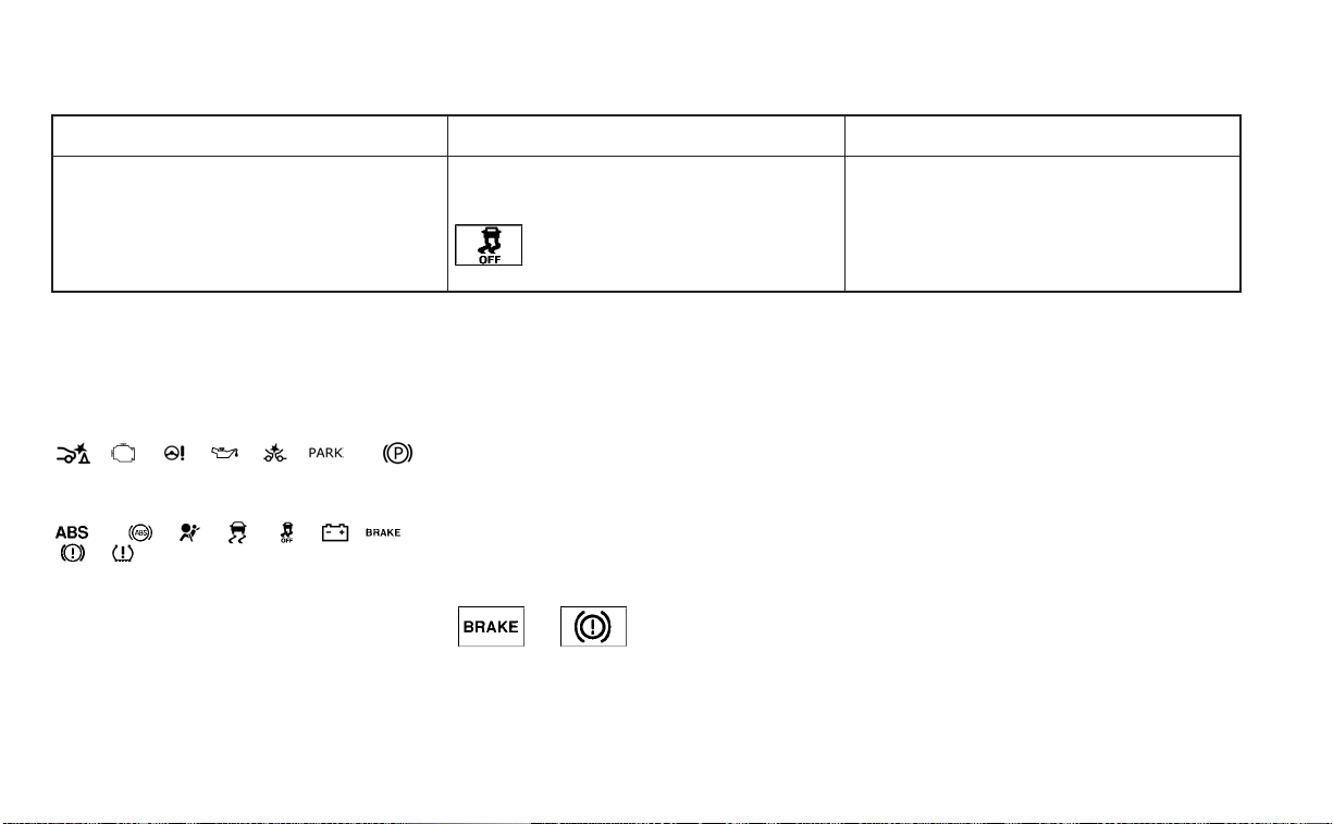
Warning/Indicator light (red) Warning/Indicator light (yellow) Warning/Indicator light (other)
Slip indicator light
Vehicle Dynamic Control (VDC) OFF indica-
tor light
CHECKING LIGHTS
With all doors closed, apply the parking
brake, fasten the seat belts and place the
ignition switch in the ON position without
starting the engine. The following lights (if
so equipped) will come on:
, , , , , or
The following lights (if so equipped) come
on briefly and then go off:
or , , , , , or
,
If any light fails to come on or operate in a
way other than described, it may indicate a
burned-out bulb and/or a system mal-
function. Have the system checked. It is
recommended that you visit a NISSAN
dealer for this service.
Some indicators and warnings are also dis-
played in the vehicle information display
between the speedometer and tachom-
eter. For additional information, see “Ve-
hicle information display-5 inch (13 cm)
Type A” (P. 2-18) or “Vehicle information
display-7 inch (18 cm) Type B” (P. 2-33).
WARNING/INDICATOR LIGHTS (red)
For additional information on warnings
and indicators, see “Vehicle information
display–5 inch (13 cm) Type A” (P. 2-18) or
“Vehicle information display—7 inch (18cm)
Type B” (P. 2-33).
or Brake warning
light
This light functions for both the parking
brake and the foot brake systems.
Parking brake indicator (if so
equipped)
When the ignition switch is placed in the ON
position, the light comes on when the park-
ing brake is applied.
Low brake fluid warning light
When the ignition switch is placed in the ON
position, the light warns of a low brake fluid
level. If the light comes on while the engine
is running with the parking brake not ap-
plied, stop the vehicle and perform the
following:
1. Check the brake fluid level. Add brake
fluid as necessary. For additional infor-
mation, see “Brake fluid” (P. 8-12).
2. If the brake fluid level is correct, have the
warning system checked. It is recom-
mended that you visit a NISSAN dealer
for this service.
2-10 Instruments and controls
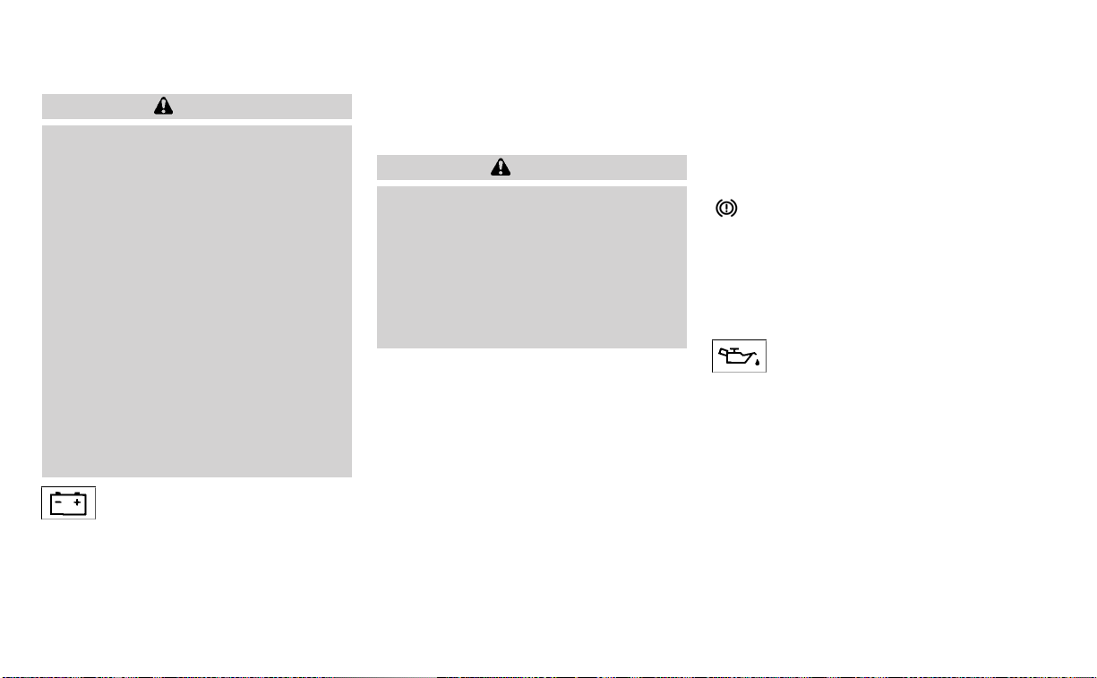
WARNING
• Your brake system may not be work-
ing properly if the warning light is on.
Driving could be dangerous. If you
judge it to be safe, drive carefully to
the nearest service station for re-
pairs. Otherwise, have your vehicle
towed because driving it could be
dangerous.
• Pressing the brake pedal with the en-
gine stopped and/or a low brake
fluid level may increase your stop-
ping distance and braking will re-
quire greater pedal effort as well as
pedal travel.
• If the brake fluid level is below the
MINIMUM or MIN mark on the brake
fluid reservoir, do not drive until the
brake system has been checked. It is
recommended that you visit a
NISSAN dealer for this service.
Charge warning light
If this light comes on while the engine is
running, it may indicate the charging sys-
tem is not functioning properly. Turn the
engine off and check the generator belt. If
the belt is loose, broken, or missing, or if the
light remains on, have the system checked.
It is recommended that you visit a NISSAN
dealer for this service.
CAUTION
• Do not ground electrical accessories
directly to the battery terminal. Do-
ing so will bypass the variable volt-
age control system and the vehicle
battery may not charge completely.
For additional information, see “Vari-
able voltage control system” (P. 8-16).
• Do not continue driving if the genera-
tor belt is loose, broken or missing.
or Electronic parking
brake indicator
light (if so
equipped)
This light illuminates when the electronic
parking brake system is operating.
When the ignition switch is placed in the ON
position, the electronic parking brake
warning light illuminates. When the engine
is started and the parking brake is released,
the warning light turns off.
If the parking brake is not released, the
electronic parking brake warning light re-
mains illuminated. Ensure the electronic
parking brake warning light has turned off
before driving.
If the electronic parking brake warning light
illuminates or flashes while the electronic
parking brake system warning light
(yellow) illuminates, it may indicate
that the electronic parking brake system is
not functioning properly. Have the system
checked. It is recommended that you visit a
NISSAN dealer for this service.
For additional information, see “Parking
brake” (P. 5-24).
Engine oil pressure
warning light
This light warns of low engine oil pressure. If
the light flickers or comes on during nor-
mal driving, pull off the road in a safe area,
stop the engine immediately and call a
NISSAN dealer or other authorized repair
shop.
The engine oil pressure warning light is
not designed to indicate a low oil level.
Use the dipstick to check the oil level. For
additional information, see “Engine oil”
(P. 8-7).
Instruments and controls 2-11
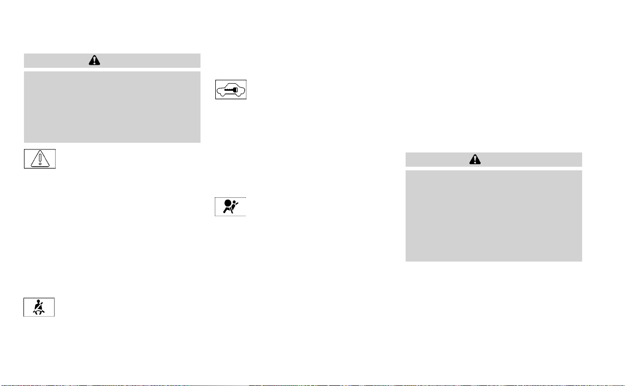
CAUTION
Running the engine with the engine oil
pressure warning light on could cause
serious damage to the engine almost
immediately. Such damage is not cov-
ered by the NISSAN New Vehicle Limited
Warranty. Turn off the engine as soon
as it is safe to do so.
Master warning light
When the ignition is in the ON position, the
master warning light illuminates if any of
the following are displayed on the vehicle
information display.
• Parking brake release warning
• Door open warning (while moving)
• Steering Alert hands on detection
warning
The warning(s) remain on the vehicle infor-
mation display until action is taken, or the
ignition is placed in the OFF position.
Seat belt warning light and
chime
The light and chime remind you to fasten
the driver and front passenger seat belts.
For additional information, see “Seat belts”
(P. 1-12).
Security indicator light
This light blinks when the ignition switch is
placed in the OFF, LOCK or AUTO ACC
position.
The blinking security indicator light indi-
cates that the security systems equipped
on the vehicle are operational.
For additional information, see “Security
systems” (P. 2-50).
Supplemental air bag
warning light
When the ignition switch is placed in the ON
or START position, the supplemental air
bag warning light illuminates for about 7
seconds and then turns off. This means the
system is operational.
If any of the following conditions occur, the
front air bag, side air bag, curtain air bag,
and pretensioner systems need servicing
and your vehicle must be taken to a NISSAN
dealer:
• The supplemental air bag warning light
remains on after approximately 7
seconds.
• The supplemental air bag warning light
flashes intermittently.
• The supplemental air bag warning light
does not come on at all.
Unless checked and repaired, the supple-
mental restraint system (air bag system)
and/or the pretensioners may not function
properly. For additional details, see “Supple-
mental Restraint System (SRS)” (P. 1-46).
WARNING
If the supplemental air bag warning
light is on, it could mean that the front
air bag, side air bag, curtain air bag sys-
tems and/or pretensioner systems will
not operate in an accident. To help
avoid injury to yourself or others, have
your vehicle checked as soon as pos-
sible. It is recommended that you visit a
NISSAN dealer for this service.
WARNING/INDICATOR LIGHTS
(yellow)
For additional information on warnings
and indicators, see “Vehicle information
display-5 inch (13 cm) Type A” (P. 2-18) or
“Vehicle information display-7 inch (18 cm)
Type B” (P. 2-33).
2-12 Instruments and controls

or Anti-lock Braking
System (ABS)
warning light
When the ignition switch is placed in the ON
position, the ABS warning light illuminates
and then turns off. This indicates the ABS is
operational.
If the ABS warning light illuminates while
the engine is running or while driving, it
may indicate the ABS is not functioning
properly. Have the system checked. It is
recommended that you visit a NISSAN
dealer for this service.
If an ABS malfunction occurs, the anti-lock
function is turned off. The brake system
then operates normally but without anti-
lock assistance. For additional information,
see “Brake system” (P. 5-148).
Automatic Emergency
Braking (AEB) with
Pedestrian Detection
system warning light
This light comes on when the ignition
switch is placed in the ON position. It turns
off after the engine is started.
This light illuminates when the AEB with
Pedestrian Detection system is set to OFF
in the vehicle information display.
If the light illuminates when the AEB with
Pedestrian Detection system is on, it may
indicate that the system is unavailable. For
additional information, see “Automatic
Emergency Braking (AEB) with Pedestrian
Detection” (P. 5-111) and “Intelligent Forward
Collision Warning (I-FCW)” (P. 5-123).
or Electronic
parking brake
warning light (if
so equipped)
The electronic parking brake system warn-
ing light functions for the electronic park-
ing brake system. If the warning light illumi-
nates, it may indicate the electronic
parking brake system is not functioning
properly. Have the system checked. It is
recommended that you visit a NISSAN
dealer for this service.
For additional information, see “Parking
brake” (P. 5-24).
Front passenger air bag
status light
The front passenger air bag status light will
be lit and the passenger front air bag will be
off depending on how the front passenger
seat is being used.
For additional information, see “Front pas-
senger air bag and status light” (P. 1-57).
Low tire pressure warning
light
Your vehicle is equipped with a Tire Pres-
sure Monitoring System (TPMS) that moni-
tors the tire pressure of all tires except the
spare.
The low tire pressure warning light warns
of low tire pressure or indicates that the
TPMS is not functioning properly.
After the ignition switch is placed in the ON
position, this light illuminates for about 1
second and turns off.
Low tire pressure warning
If the vehicle is being driven with low tire
pressure, the warning light will illumi-
nate. A “Tire Pressure Low - Add Air”
warning also appears in the vehicle in-
formation display.
Instruments and controls 2-13

When the low tire pressure warning light
illuminates, you should stop and adjust
the tire pressure of all four tires to the
recommended COLD tire pressure shown
on the Tire and Loading Information la-
bel located in the driver's door opening.
The low tire pressure warning light does
not automatically turn off when the tire
pressure is adjusted. After the tire is in-
flated to the recommended pressure,
the vehicle must be driven at speeds
above 16 mph (25 km/h) to activate the
TPMS and turn off the low tire pressure
warning light. Use a tire pressure gauge
to check the tire pressure.
The “Tire Pressure Low - Add Air” warning
appears each time the ignition switch is
placed in the ON position as long as the low
tire pressure warning light remains
illuminated.
For additional information, see “Vehicle in-
formation display — 7 inch (18 cm) Type B”
(P. 2-33), and “Tire Pressure Monitoring Sys-
tem (TPMS)” (P. 5-5) and (P. 6-3).
TPMS malfunction
If the TPMS is not functioning properly, the
low tire pressure warning light will flash for
approximately 1 minute when the ignition
switch is placed in the ON position. The
light will remain on after 1 minute. Have the
system checked. It is recommended that
you visit a NISSAN dealer for this service.
The "Tire Pressure Low — Add Air" warning
does not appear if the low tire pressure
warning light illuminates to indicate a
TPMS malfunction.
For additional information, see “Tire Pres-
sure Monitoring System (TPMS)” (P. 5-5) and
(P. 6-3).
WARNING
• Radio waves could adversely affect
electric medical equipment. Those
who use a pacemaker should contact
the electric medical equipment
manufacturer for the possible influ-
ences before use.
• If the light does not illuminate with
the ignition switch placed in the ON
position, have the vehicle checked as
soon as possible. It is recommended
that you visit a NISSAN dealer for this
service.
• If the light illuminates while driving,
avoid sudden steering maneuvers or
abrupt braking, reduce vehicle
speed, pull off the road to a safe loca-
tion and stop the vehicle as soon as
possible. Driving with under-inflated
tires may permanently damage the
tires and increase the likelihood of
tire failure. Serious vehicle damage
could occur and may lead to an acci-
dent and could result in serious per-
sonal injury or death. Check the tire
pressure for all four tires. Adjust the
tire pressure to the recommended
COLD tire pressure show on the Tire
and Loading Information label lo-
cated in the driver’s door opening to
turn the low tire pressure warning
light off. If the light still illuminates
while driving after adjusting the tire
pressure, a tire may be flat or the
TPMS may be malfunctioning. If you
have a flat tire, replace it with a spare
tire as soon as possible. If no tire is
flat and all tires are properly inflated,
have the vehicle checked. It is recom-
mended that you visit a NISSAN
dealer for this service.
2-14 Instruments and controls

• When using a wheel without the
TPMS such as the spare tire, the TPMS
will not function and the low tire
pressure warning light will flash for
approximately 1 minute. The light will
remain on after 1 minute. Have your
tires replaced and/or TPMS system
reset as soon as possible. It is recom-
mended that you visit a NISSAN
dealer for these services.
• Replacing tires with those not origi-
nally specified by NISSAN could af-
fect the proper operation of the
TPMS.
CAUTION
• The TPMS is not a substitute for the
regular tire pressure check. Be sure
to check the tire pressure regularly.
• If the vehicle is being driven at
speeds of less than 16 mph (25 km/h),
the TPMS may not operate correctly.
• Be sure to install the specified size of
tires to the four wheels correctly.
Malfunction Indicator Light
(MIL)
If this indicator light comes on steady or
blinks while the engine is running, it may
indicate a potential emission control
malfunction.
The MIL may also come on steady if the
fuel-filler cap is loose or missing, or if the
vehicle runs out of fuel. Check to make sure
the fuel-filler cap is installed and closed
tightly, and that the vehicle has at least 3
gallons (11.4 liters) of fuel in the fuel tank.
After a few driving trips, the
light
should turn off if no other potential emis-
sion control system malfunction exists.
If this indicator light comes on steady for 20
seconds and then blinks for 10 seconds
when the engine is not running, it indicates
that the vehicle is not ready for an emission
control system inspection/maintenance
test. For additional information, see “Readi-
ness for Inspection/Maintenance (I/M) test”
(P. 10-24).
Operation
The MIL will come on in one of two ways:
• MIL on steady — An emission control sys-
tem malfunction has been detected.
Check the fuel-filler cap if the Loose Fuel
Cap warning appears in the vehicle infor-
mation display. If the fuel-filler cap is loose
or missing, tighten or install the cap and
continue to drive the vehicle. The
light should turn off after a few driving
trips. If the
light does not turn off
after a few driving trips, have the vehicle
inspected. It is recommended that you
visit a NISSAN dealer for this service. You
do not need to have your vehicle towed
to the dealer.
• MIL blinking — An engine misfire has been
detected which may damage the emis-
sion control system. To reduce or avoid
emission control system damage:
– do not drive at speeds above 45 mph
(72 km/h).
– avoid hard acceleration or
deceleration.
– avoid steep uphill grades.
– if possible, reduce the amount of cargo
being hauled or towed.
Instruments and controls 2-15

The MIL may stop blinking and come on
steady. Have the vehicle inspected. It is rec-
ommended that you visit a NISSAN dealer
for this service. You do not need to have
your vehicle towed to the dealer.
CAUTION
Continued vehicle operation without
having the emission control system
checked and repaired as necessary
could lead to poor driveability, reduced
fuel economy, and possible damage to
the emission control system.
Master warning light
When the ignition is in the ON position, the
master warning light illuminates if any of
the following are displayed on the vehicle
information display.
• No key warning
• Low windshield-washer fluid warning
• Door open warning (when stopped)
• Trunk open warning
• Loose fuel cap
• Low tire pressure warning
• AWD warning
If the master warning light illuminates and
the message(s) are not visible on the ve-
hicle information display, use the buttons
located on the steering wheel to navigate
the vehicle information display until the
“Warnings” screen is displayed.
Power steering warning
light
WARNING
• If the engine is not running or is
turned off while driving, the power
assist for the steering will not work.
Steering will be harder to operate.
• When the power steering warning
light illuminates with the engine run-
ning, there will be no power assist for
the steering. You will still have control
of the vehicle, but the steering will be
harder to operate. Have the power
steering system checked. It is recom-
mended that you visit a NISSAN
dealer for this service.
When the ignition switch is placed in the ON
position, the power steering warning light
illuminates. After starting the engine, the
power steering warning light turns off. This
indicates the power steering is operational.
If the power steering warning light illumi-
nates while the engine is running, it may
indicate the power steering is not function-
ing properly and may need servicing. Have
the power steering checked. It is recom-
mended that you visit a NISSAN dealer for
this service.
When the power steering warning light illu-
minates with the engine running, there will
be no power assist for the steering, but you
will still have control of the vehicle. At this
time, greater steering effort is required to
operate the steering wheel, especially in
sharp turns and at low speeds.
For additional information, see “Power
steering” (P. 5-147).
Rear Automatic Braking
(RAB) warning light (if so
equipped)
This light comes on when the ignition
switch is placed in the ON position. It turns
off after the engine is started.
This light illuminates when the RAB system
is turned off in the vehicle information
display.
If the light illuminates when the RAB sys-
tem is on, it may indicate that the system is
2-16 Instruments and controls
unavailable. For additional information, see
“Rear Automatic Braking (RAB)” (P. 5-104).
Slip indicator light
This indicator light will blink when the Ve-
hicle Dynamic Control (VDC) system is op-
erating, thus alerting the driver to the fact
that the road surface is slipper y and the
vehicle is nearing its traction limits.
You may feel or hear the system working;
this is normal.
The light will blink for a few seconds after
the VDC system stops limiting wheel spin.
The
indicator light also comes on
when you place the ignition switch in the
ON position. The light will turn off after ap-
proximately 2 seconds if the system is op-
erational. If the light does not come on
have the system checked. It is recom-
mended that you visit a NISSAN dealer for
this service.
Vehicle Dynamic Control
(VDC) OFF indicator light
This indicator light comes on when the
VDC is turned off in the vehicle information
display. This indicates the VDC has been
turned off.
Turn the VDC on using the vehicle informa-
tion display, or by restarting the engine. For
additional information, see “Vehicle Dy-
namic Control (VDC) system” (P. 5-150).
The VDC light also comes on when the ig-
nition switch is placed in the ON position.
The light will turn off after a period of time if
the system is operational. If the light stays
on or comes on along with the
indica-
tor light while you are driving, have the VDC
system checked. It is recommended that
you visit a NISSAN dealer for this service.
WARNING
VDC should remain on unless freeing a
vehicle from mud or snow.
While the VDC system is operating, you
might feel a slight vibration or hear the sys-
tem working when starting the vehicle or
accelerating, but this is normal.
WARNING/INDICATOR LIGHTS
(other)
For additional information on warnings
and indicators, see “Vehicle information
display-5 inch (13 cm) Type A” (P. 2-18) or
“Vehicle information display 7 inch (18 cm)
Type B” (P. 2-33).
Automatic brake hold
indicator light (white/green)
(if so equipped)
The automatic brake hold indicator light
(white) illuminates when the automatic
brake hold system is on standby.
The automatic brake hold indicator light
(green) illuminates when the automatic
brake hold system is operating.
For additional information, see “Automatic
brake hold” (P. 5-27).
Front fog light indicator
light (green) (if so
equipped)
The front fog light indicator light illumi-
nates when the front fog lights are on. For
additional information, see “Fog light
switch” (P. 2-61).
High Beam Assist indicator
light (green) (if so equipped)
This indicator light illuminates when the
headlights come on while the headlight
switch is in the AUTO position with the high
beams selected. This indicates that the
high beam assist is operational.
Instruments and controls 2-17

For additional information, see “Headlight
and turn signal switch” (P. 2-55).
High beam indicator light
(blue)
This blue light comes on when the head-
light high beams are on and goes out when
the low beams are selected.
The high beam indicator light also comes
on when the passing signal is activated.
Side light and headlight
indicator light (green)
The side light and headlight indicator light
illuminates when the side light or headlight
position is selected. For additional informa-
tion, see “Headlight and turn signal switch”
(P. 2-55).
Turn signal/hazard
indicator lights (green)
The appropriate light flashes when the turn
signal switch is activated.
Both lights flash when the hazard switch is
turned on.
AUDIBLE REMINDERS
Brake pad wear warning
The disc brake pads have audible wear
warnings. When a disc brake pad requires
replacement, it makes a high pitched
scraping sound when the vehicle is in mo-
tion, whether or not the brake pedal is de-
pressed. Have the brakes checked as soon
as possible if the warning sound is heard.
Light reminder chime
With the ignition switch placed in the OFF
position, a chime sounds when the driver's
door is opened if the headlights or parking
lights are on.
Turn the headlight control switch off before
leaving the vehicle.
NISSAN Intelligent Key® door
buzzer
The Intelligent Key door buzzer sounds if
the Intelligent Key is left inside the vehicle
when locking the doors. When the buzzer
sounds, be sure to check both the vehicle
and the Intelligent Key. For additional infor-
mation, see “NISSAN Intelligent Key®” (P. 3-2).
The vehicle information display is located
to the left of the speedometer. It displays
such items as:
• Vehicle settings
• Indicators and warnings
• Information/warning messages
• Tire pressure information
• Drive computer information
• Cruise control system information
• Driving Aids (if so equipped)
• NISSAN Intelligent Key® operation
information
• Audio information
LIC2630
VEHICLE INFORMATION DISPLAY-
5 INCH (13 cm) TYPE A (if so equipped)
2-18 Instruments and controls

• Shift position
• Distance to empty
• Odometer/twin trip odometer
• Clock and outside temperature
HOW TO USE THE VEHICLE
INFORMATION DISPLAY
The vehicle information display can be
changed using the
,
, and OK buttons located on the steer-
ing wheel.
䊊
1
- Use these buttons
to navigate the vehicle information
display.
䊊
2
OK - Change or select an item in the
vehicle information display.
䊊
3
— Returns to the previous menu.
The OK,
and buttons also
control audio and control panel functions
in some conditions. Most screens and
menus offer instruction prompts of the
steering switch buttons to indicate how to
control the vehicle information display. The
OK button changes the audio source and
the
buttons also control voice
recognition manual mode. The OK button
can be used to change the audio source
when the audio screen is displayed. The
buttons can be used when con-
trolling voice recognition prompts manu-
ally. For additional information, refer to the
separate NissanConnect® Owner’s Manual.
STARTUP DISPLAY
When the vehicle in placed in the ON posi-
tion the vehicle information display may
display the following screens (if so
equipped):
• Drive Computer — Speed, Trip Distance &
Time, Fuel Economy
• Audio
• Driving Aids
• Tire Pressure
• Settings
• Warnings*
LIC3566
Instruments and controls 2-19

*Warnings will only display if there are any
present. For additional information, see
“Vehicle information display warnings and
indicators” (P. 2-27).
To control what items display in the vehicle
information display, see “How to use the
vehicle information display” (P. 2-19).
RESETTING THE DRIVE COMPUTER
The drive computer is divided across three
screens:
• Speed
• Trip Distance & Time
• Fuel Economy
1. Press the
or buttons until the
desired drive computer screen is
displayed.
2. Press the OK button to bring up the drive
computer Reset menu.
3. Use the
or to select the de-
sired option. Then press the OK button:
• “Cancel” — returns to the previous screen
without resetting the trip computer.
• Drive computer value — resets only the
displayed drive computer value.
– “Average Speed” - resets the average
speed of the selected drive computer
screen.
– “Distance & Time” - resets the distance
and time of the selected drive com-
puter screen.
– “Fuel Economy” - resets the fuel
economy of the selected drive com-
puter screen.
• “All” — resets all linked drive computer val-
ues. This includes distance & time, aver-
age fuel economy and average speed
information.
OIL CONTROL SYSTEM (if so
equipped)
The oil control system can be accessed in
the Maintenance portion of the vehicle in-
formation display settings.
Engine oil information informs the distance
to oil change. Never exceed one year or
7,500 miles (12,000 km) between oil change
intervals for the 2.0L 4 cylinder (KR20DDET
engine model) or 10,000 miles (16,000 km)
between oil change intervals for the 2.5L 4
cylinder (PR25DD engine model).
Display when
ignition is ON
Display timing Action Required
Engine Oil Ser-
vice due in xxx
kilometers
Remaining oil
life is less than
940 miles (1500
km).
Plan to have
your vehicle
serviced.
Service due
now
Remaining oil
lifeis0miles(0
km).
Have your ve-
hicle serviced
within two
weeks or less
than 500 miles
(800 km).
The oil change interval cannot be adjusted
manually.
The distance to oil change interval is calcu-
lated depending on the driving conditions
and set automatically by the oil control sys-
tem. A reminder will be displayed when ap-
proaching the end of the service interval.
When the Factory Reset option is selected
in the vehicle information display, the oil
control system will also be reset to initial
value. Please change the engine oil when
Factory Reset is selected.
2-20 Instruments and controls
CAUTION
If the oil replacement indicator is dis-
played, change the engine oil within
two weeks or less than 500 miles (800
km).
Operating the vehicle with deteriorated
oil can damage the engine.
To reset oil control system:
1. Place the ignition switch in the ON
position.
2. Press the
and buttons located
on the steering wheel until “Settings” dis-
plays in the vehicle information display.
Use
to select “Maintenance”.
Then, press the OK button.
3. Select “Oil Control System” and press the
OK button.
4. Press the OK button according to the
reset instructions displayed at the bot-
tom of the “Oil Control System” mainte-
nance screen.
5. For additional information, refer to the
separate maintenance booklet.
SETTINGS
The setting mode allows you to change the
information displayed in the vehicle infor-
mation display. It also allows you to change
vehicle functions:
• VDC
• Driver Assistance
• Clock
• Display Settings
• Vehicle Settings
• Maintenance
• Alarm
• Tire Pressures
• Unit
• Language
• Factory Reset
VDC
The VDC Setting menu allows the user to enable or disable the Vehicle Dynamic Control (VDC) system.
Menu item Explanation
VDC Allows the user turn the VDC system on or off. For additional information, see “Vehicle Dynamic Control (VDC) system”
(P. 5-150).
Instruments and controls 2-21

Driver Assistance
The driver assistance menu allows the user to change the settings for driving, parking, and braking aids.
Some menu items shown below may not be equipped on your vehicle.
Menu item Explanation
Driving Aids Displays available driving aids.
Emergency Brake Displays available emergency brake options.
Front Allows the user to turn the emergency braking system on or off. For additional information, see “Automatic Emer-
gency Braking (AEB) with Pedestrian Detection ” (P. 5-111) and “Intelligent Forward Collision Warning (I-FCW)”
(P. 5-123).
Rear Allows the user to turn the rear emergency braking system on or off. For additional information, see “Rear Auto-
matic Braking (RAB)” (P. 5-104).
Lane Displays available lane options.
Lane (LDW) Allows the user to turn the Lane Departure Warning (LDW) system on or off. For additional information, see “Lane
Departure Warning (LDW)” (P. 5-33).
Blind Spot Displays available emergency brake options.
Blind Spot (BSW) Allows the user to turn the Blind Spot Warning (BSW) system on or off. For additional information, see “Blind Spot
Warning (BSW) ” (P. 5-46).
Indicator Brightness Allows user to change the brightness of the side indicator.
Driver Attention Allows user to turn the Intelligent Driver Alertness on or off. For additional information, see “Intelligent Driver Alert-
ness” (P. 5-138).
Parking Aids Displays available parking aids.
Cross Traffic Allows user to turn the Rear Cross Traffic Alert (RCTA) system on or off. For additional information, see “ Rear Cross
Traffic Alert (RCTA)” (P. 5-58).
Rear Sensor Allows user to turn the rear sonar on or off.
Display Allows user to turn the display on or off.
Volume Allows the user to set the parking sensor volume to High/Med./Low.
Range Allows user to set the distance sensor range to Far/Mid./Near.
Chassis Control Displays available chassis control options.
Trace Control Allows user to turn the Intelligent Trace Control system on or off. For additional information, see “ Intelligent Trace
Control (I-TC)” (P. 5-153).
2-22 Instruments and controls

Clock
Menu item Explanation
Clock Allows user to adjust the clock settings and time within the vehicle information display. Adjustments that can
be made include manually setting the time, 12H/24H format, Daylight Saving Time, and time zone.
The clock can also be set within the center display. For additional information, refer to the separate
NissanConnect® Owner’s Manual.
Display Settings
The display settings menu allows the user to customize the information that appears in the vehicle information display.
Some menu items shown below may not be equipped on your vehicle.
Menu item Explanation
Main Menu Selection Displays available screens that can be shown in the vehicle information display.
Speed Allows user to turn the speedometer screen on or off in the vehicle information display.
Trip Allows user to turn the trip computer on or off in the vehicle information display.
Fuel Economy Allows user to turn the fuel economy screen on or off in the vehicle information display.
Audio Allows user to turn the audio controls screen on or off in the vehicle information display.
Driving Aids Allows user to turn the driving aids screen on or off in the vehicle information display.
Tire pressures Allows user to turn the tire pressure screen on or off in the vehicle information display.
Welcome Effect Displays the available welcome effect settings.
Dial Effect Allows user to turn the dial effect on or off.
Display Effect Allows user to turn the display effect on or off.
Light/Wiper Displays the available light and wiper guidance settings.
Light Guidance Allows user to turn the light mode guidance on or off.
Wiper Guidance Allows user to turn the wiper mode guidance on or off.
Instruments and controls 2-23

Vehicle Settings
The vehicle settings allow the user to change the settings for lights, wipers, locking, keys, and other vehicle settings.
Some menu items shown below may not be equipped on your vehicle.
Menu item Explanation
Lighting Displays the available lighting options.
Welcome Light Allows user to turn the welcome light on or off.
Auto Room Lamp Allows user to turn the interior light timer on or off.
Light Sensitivity Allows user to change when the auto lights activate based on exterior brightness.
Light Off Delay Allows user to change the length of time the exterior lights remain on.
Turn indicator Displays the available turn indicator options.
3 Flash Pass Allows user to turn the 3 flash pass on or off.
Locking Displays the available locking options.
I-Key Door Lock Allows the user to turn the I-Key door lock on or off. When on, the request switch on the door is activated.
Selective Unlock Allows user to turn selective unlock on or off. When turned on, only the driver’s door is unlocked after the door unlock operation.
When the door handle request switch on the driver’s or front passenger’s side door is pushed to be unlocked, only the corre-
sponding door is unlocked first. All the doors can be unlocked if the door unlock operation is performed again within 5 seconds.
When this item is turned off, all the doors will be unlocked after the door unlock operation is performed once.
Auto Door Unlock Displays the auto door unlock options.
Off Doors will have to be manually unlocked.
Ignition OFF Doors will unlock when the ignition is turned off.
Shift to Park Doors will unlock when the vehicle is shifted into Park.
Answer Back Horn Allows user to turn answer back horn on or off. When turned on, the horn will chirp and the hazard indicators will flash once
when locking the vehicle with the Intelligent Key.
Wipers Displays the available wiper options.
Speed Dependent Allows user to turn wiper with speed on or off.
Rear Door Alert Displays the available Rear Door Alert options. For additional information, see “Rear Door Alert” (P. 2-65).
Horn & Alert When selected, the alert is displayed and the horn sounds.
Alert Only When selected, only the alert is displayed.
OFF When selected, no alert or horn will be active.
Remote Start Allows user to turn the Remote Engine Start on or off. When turned on, the engine can be started remotely. For additional infor-
mation, see “Remote Engine Start” (P. 3-19).
2-24 Instruments and controls
Maintenance
The maintenance menu allows the user to set reminders for various vehicle maintenance items.
WARNING
The tire replacement indicator is not a substitute for regular tire checks, including tire pressure checks. For additional informa-
tion, see “Changing wheels and tires” (P. 8-38). Many factors including tire inflation, alignment, driving habits and road conditions
affect tire wear and when tires should be replaced. Setting the tire replacement indicator for a certain driving distance does not
mean your tires will last that long. Use the tire replacement indicator as a guide only and always perform regular tire checks.
Failure to perform regular tire checks, including tire pressure checks could result in tire failure. Serious vehicle damage could
occur and may lead to a collision, which could result in serious personal injury or death.
Menu item Explanation
Maintenance Displays various maintenance reminder options.
Oil Control System Allows user to reset the current interval. This should only be done after completing oil change maintenance.
Oil Filter Allows user to set a reminder at a specific interval or reset the current one.
Tire Allows user to set a reminder at a specific interval or reset the current one.
Other Allows user to set a reminder at a specific interval or reset the current one.
Alarm
The alarms menu allows the user to set various alerts.
Menu item Explanation
Timer Alert Allows user to set the timer alert for a specific interval.
Phone Allows user to turn the phone alert on or off.
Instruments and controls 2-25

Tire Pressures
The TPMS settings menu allows the user to change the tire pressure units displayed in the vehicle information display.
Menu item Explanation
Tire Pressures Displays available tire pressure settings.
Tire Pressure Unit Allows user to select the tire pressure units that will display in the vehicle information display.
Unit
The units menu allows the user to change the units shown in the vehicle information display.
Some menu items shown below may not be equipped on your vehicle.
Menu item Explanation
Mileage Allows user to select different mileage display units.
Tire Pressures Allows user to select different pressure display units.
Temperature Allows user to select different temperature display units.
Language
The language menu allows the user to change the languages displayed in the vehicle information display.
Menu item Explanation
Language Displays available language options for the vehicle information display.
Factory Reset
The factory reset menu allows the user to restore the vehicle information display settings to factory status.
Menu item Explanation
Factory Reset
Allows user to reset the vehicle information display settings to the original factory settings. Once selected,
the user can confirm or cancel the reset.
2-26 Instruments and controls

VEHICLE INFORMATION DISPLAY
WARNINGS AND INDICATORS
The following messages may appear in
your vehicle information display.
Engine start operation for
Intelligent Key system (if
I-Key batter y level is low)
This indicator appears when the battery of
the Intelligent Key is low and when the In-
telligent Key system and the vehicle are not
communicating normally.
If this appears, touch the ignition switch
with the Intelligent Key while depressing
the brake pedal. For additional information,
see “NISSAN Intelligent Key® batter y dis-
charge” (P. 5-15).
Key Battery Low
This indicator appears when the Intelligent
Key battery is running out of power.
If this indicator appears, replace the bat-
tery with a new one. For additional infor-
mation, see “Battery replacement” (P. 8-23).
Key ID Incorrect
This warning appears when the ignition
switch is placed from the OFF position and
the Intelligent Key is not recognized by the
system. You cannot start the engine with
an unregistered key.
For additional information, see “NISSAN In-
telligent Key®” (P. 3-7).
Key System Error: See
Owner’s Manual
After the ignition switch is placed in the ON
position, this warning appears for a period
of time and then turns off.
The Key System Error message warns of a
malfunction with the Intelligent Key sys-
tem. If the warning appears while the en-
gine is stopped, it may be impossible to
start the engine.
If the warning appears while the engine is
running, you can drive the vehicle. However,
in these cases, have the system checked. It
is recommended that you visit a NISSAN
dealer for this service.
No Key Detected
This warning appears when the Intelligent
Key is left outside the vehicle with the igni-
tion switch in the ON position. Make sure
the Intelligent Key is inside the vehicle.
For additional information, see “NISSAN In-
telligent Key®” (P. 3-2).
Alarm— Time for a driver
break
This indicator appears when the set time is
reached. The time can be set up to six
hours. For additional information, see “Set-
tings” (P. 2-21).
Chassis Control System Error: See
Owner’s Manual
This warning appears if there is an error in
the Automatic Brake Hold system. Have the
system checked. It is recommended that
you visit a NISSAN dealer for this service. For
additional information, see “Chassis con-
trol” (P. 5-153) or “Automatic brake hold”
(P. 5-27).
Rear Door Alert is activated
When the system is enabled, this message
appears when the Rear Door Alert system
is active and can remind the driver to check
the back seat.
Instruments and controls 2-27

• Using the steering wheel switch, a driver
can select “Dismiss Message” to clear the
display for a period of time. If no selection
is made, this message automatically
turns off after a period of time.
• Using the steering wheel switch, a driver
can select “Disable Alert” to disable the
horn alert for the remainder of the cur-
rent trip.
WARNING
Selecting “Dismiss Message” during a
stop within a trip temporarily dis-
misses the message for that stop with-
out turning the system off. Alerts can
be provided for other stops during the
trip. Selecting “Disable Alert” turns off
the Rear Door Alert system for the re-
mainder of a trip and no audible alert
will be provided.
NOTE:
This system is disabled until a driver en-
ables it using the vehicle information
display. For additional information, see
“How to use the vehicle information dis-
play” (P. 2-34).
For additional information, see “Rear Door
Alert” (P. 2-65).
Check Rear Seat For All Articles
When the system is enabled, this message
appears when the vehicle comes to a com-
plete stop, the vehicle is transitioned from
the D (Drive) position to P (Park) position,
and the driver exits the vehicle. This mes-
sage alerts the driver, after a period of time,
to check for items in the rear seat after the
audible alert has been provided.
NOTE:
This system is disabled until a driver en-
ables it using the vehicle information
display. For additional information, see
“How to use the vehicle information dis-
play” (P. 2-34).
For additional information, see “Rear Door
Alert” (P. 2-65).
Door/Trunk Open
This warning appears when a door or the
trunk has been opened.
Drive sport mode indicator
A small “S” appears to the right of the Trans-
mission Shift Position indicator in the ve-
hicle information display when the drive
sport mode is engaged.
Activate the drive sport mode by pushing
the switch on the shift lever while the shift
lever is in the D (Drive) position.
For additional information, see “Driving the
vehicle” (P. 5-18).
Engine Oil Service due in – –
– miles
This distance to oil change is displayed if
the distance to oil change is less than 62
miles (100 km).
Loose Fuel Cap
This warning appears when the fuel-filler
cap is not tightened correctly after the ve-
hicle has been refueled. For additional in-
formation, see “Fuel-filler cap” (P. 3-25).
Low Fuel
This warning appears when the fuel level in
the fuel tank is getting low. Refuel as soon
as it is convenient, preferably before the
fuel gauge reaches 0 (Empty). There will be
a small reserve of fuel in the tank when
the fuel gauge needle reaches 0 (Empty).
2-28 Instruments and controls

Low Oil Pressure Stop
Vehicle
This warning appears if low oil pressure is
detected.
If the warning appears during normal driv-
ing, pull off the road in a safe area and stop
the engine immediately. Have the system
checked. It is recommended that you visit a
NISSAN dealer or other authorized repair
shop for this service.
The low oil pressure warning is not de-
signed to indicate a low oil level. Use the
dipstick to check the oil level. For additional
information, see “Engine oil” (P. 8-7).
Low outside temperature
indicator
This indicator appears if the outside tem-
perature is below 37°F (3°C). The tempera-
ture can be changed to display in Fahren-
heit or Celsius. For additional information,
see “Unit” (P. 2-26).
Low Washer Fluid
This warning appears when the
windshield-washer fluid is at a low level.
Add windshield-washer fluid as necessary.
For additional information, see
“Windshield-washer fluid” (P. 8-13).
Power will turn off to save the battery
This message appears after a period of
time if the ignition switch is in the AUTO
ACC or the ON position and if the vehicle is
in P (Park). For additional information, see
“Push-button ignition switch positions”
(P. 5-14).
Power turned off to save the battery
This message appears after the ignition
switch is automatically turned off. For addi-
tional information, see “Push-button igni-
tion switch positions” (P. 5-14).
Push brake and start
button to drive
This indicator appears when the shift lever
is in the P (Park) position and the vehicle
has not been started. Start the engine by
pushing the ignition switch with the brake
pedal depressed. You can start the engine
from any position of the ignition switch.
This message also appears when the ve-
hicle has been started using the Remote
Engine Start function (if so equipped). Push
the ignition switch with the brake pedal
depressed to place the ignition switch in
the ON position. For additional information,
see “Remote Engine Start” (P. 3-19).
Push Ignition to OFF
After the Push Ignition to OFF warning ap-
pears, the warning will appear if the ignition
switch is placed in the AUTO ACC position
when the shift lever is moved to the P (Park)
position.
To turn the warning off, place the ignition
switch in the ON position and then in the
LOCK position.
Reminder Turn OFF
Headlights
This warning appears when the headlights
are left in the ON position when exiting the
vehicle. Place the headlight switch in the
OFF or AUTO position. For additional infor-
mation, see “Headlight and turn signal
switch” (P. 2-55).
Release Parking Brake
This warning appears when the parking
brake is set and the vehicle is driven.
Instruments and controls 2-29

Shift to Park
This warning appears when the ignition
switch is in the AUTO ACC or OFF position
and the shift lever is not in the P (Park)
position. Also, a chime sounds when the
ignition switch is in the AUTO ACC or OFF
position.
If this warning appears, move the shift lever
to the P (Park) position and start the engine.
Shipping Mode On Push Storage Fuse
This warning may appear if the extended
storage switch is not pushed in. When this
warning appears, push in the extended
storage switch to turn off the warning. For
additional information, see “Extended stor-
age switch” (P. 2-68).
Tire Pressure Low - Add Air
This warning appears when the low tire
pressure warning light in the meter illumi-
nates and low tire pressure is detected. The
warning appears each time the ignition
switch is placed in the ON position as long
as the low tire pressure warning light re-
mains illuminated. If this warning appears,
stop the vehicle and adjust the tire pres-
sures of all four tires to the recommended
COLD tire pressure shown on the Tire and
Loading Information label. For additional
information, see “Low tire pressure warning
light” (P. 2-13) and “Tire Pressure Monitoring
System (TPMS)” (P. 5-5).
Transmission Shift Position
indicator
This indicator shows the transmission shift
position.
AWD Error: See Owner’s
Manual
This warning appears when the All-Wheel
Drive (AWD) system is not functioning prop-
erly while the engine is running.
AWD High Temp. Stop
Vehicle
This warning may appear while trying to
free a stuck vehicle due to increased oil
temperature. The driving mode may
change to 2-Wheel Drive (2WD). If this warn-
ing is displayed, stop the vehicle with the
engine idling, as soon as it is safe to do so.
Then if the warning turns off, you can con-
tinue driving.
Tire Size Incorrect See
Owner’s Manual
This warning may appear if there is a large
difference between the diameters of the
front and rear wheels. Pull off the road in a
safe area, with the engine idling. Check that
all the tire sizes are the same, that the tire
pressure is correct and that the tires are
not excessively worn.
Service CVT
This warning appears when there is a
problem with the CVT system. If this warn-
ing appears, have the system checked. It is
recommended that you visit a NISSAN
dealer for this service.
CVT hot Power reduced
This transmission has a high fluid tem-
perature protection mode. If the fluid tem-
perature becomes too high (for example,
climbing steep grades in high tempera-
tures with heavy loads, such as when tow-
ing a trailer), engine power and, under
some conditions, vehicle speed will be de-
creased automatically to reduce the
chance of transmission damage. Vehicle
speed can be controlled with the accelera-
tor pedal, but the engine and vehicle speed
may be reduced.
2-30 Instruments and controls

WARNING
When the high fluid temperature pro-
tection mode operation occurs, vehicle
speed may be gradually reduced. The
reduced speed may be lower than
other traffic, which could increase the
chance of a collision. Be especially
careful when driving. If necessary, pull
to the side of the road at a safe place
and allow the transmission to return to
normal operation; or have it repaired if
necessary.
Engine Stalled: Stop safely
This message appears 30 seconds before
the vehicle is shut down due to an above
normal operating exhaust temperature.
The Malfunction Indicator Light (MIL) and
malfunction warning (red) will illuminate.
Have the system checked. It is recom-
mended that you visit a NISSAN dealer im-
mediately for this service.
Engine Malfunction Power reduced
Service now
This warning appears when the engine is
not operating under normal conditions. If
this warning appears, have the system
checked. It is recommended that you visit a
NISSAN dealer for this service.
Engine Malfunction Service now
This warning appears when there is a prob-
lem with the engine. If this warning appears,
have the system checked. It is recommended
that you visit a NISSAN dealer for this service.
Engine hot Power reduced
This engine has a high fluid temperature
protection mode. If the fluid temperature
becomes too high (for example, climbing
steep grades in high temperatures with
heavy loads, such as when towing a trailer),
engine power and, under some conditions,
vehicle speed will be decreased automati-
cally to reduce the chance of engine dam-
age. Vehicle speed can be controlled with
the accelerator pedal, but the engine and
vehicle speed may be reduced.
WARNING
When the high fluid temperature protec-
tion mode operation occurs, vehicle
speed may be gradually reduced. The re-
duced speed may be lower than other
traffic, which could increase the chance
of a collision. Be especially careful when
driving. If necessary, pull to the side of
the road at a safe place and allow the
engine to return to normal operation; or
have it repaired if necessary.
Automatic Emergency
Braking (AEB) with
Pedestrian Detection
emergency warning
indicator
This indicator appears along, with an au-
dible warning, when the system detects
the possibility of a forward collision.
For additional information, see “Automatic
Emergency Braking (AEB) with Pedestrian
Detection” (P. 5-111).
Blind Spot Warning (BSW)
indicator
This indicator appears when the BSW sys-
tem is engaged.
For additional information, see “Blind Spot
Warning (BSW)” (P. 5-46).
Cruise control indicator
This indicator shows the cruise control sys-
tem status.
When cruise control is activated, a green
circle will appear to indicate it is set. The
vehicle information display will also display
the speed the cruise control was set at. If
you accelerate past the set speed, the
speed will blink until you either cancel
cruise control or go back to the set speed. If
Instruments and controls 2-31

cruise control is on and canceled, the
speed will be displayed to show the speed
the vehicle will return to if the resume but-
ton is activated.
Forward Driving Aids Temporarily
Disabled Front Sensor Blocked See
Owner’s Manual
This message appears when the front ra-
dar sensor may be obstructed due to:
• mud, dirt, snow, ice, etc.
• inclement weather (rain, fog, snow, etc.).
All forward driving aids are temporarily dis-
abled until the system detects that the
front radar sensor is no longer obstructed.
For additional information, see:
• Automatic Emergency Braking (AEB) with
Pedestrian Detection (P. 5-111).
• Intelligent Forward Collision Warning (I-
FCW ) (P. 5-123).
Intelligent Driver
Alertness— Take a break?
This alert appears when the system has
detected that the driver may be displaying
fatigue or a lack of attention.
Lane Departure Warning
(LDW) indicator
This indicator appears when the LDW sys-
tem is engaged.
For additional information, see “Lane De-
parture Warning (LDW)” (P. 5-33).
Malfunction See Owner’s Manual
This warning appears when one of the fol-
lowing systems (if so equipped) is not func-
tioning properly:
• Automatic Emergency Braking (AEB) with
Pedestrian Detection
• Blind Spot Warning (BSW)
• Driver Attention Alert
• Intelligent Forward Collision Warning
(I-FCW )
• Lane Departure Warning (LDW )
• Rear Automatic Braking (RAB)
• Rear Cross Traffic Alert (RCTA)
If one or more of these warning appears,
have the system checked. It is recom-
mended that you visit a NISSAN dealer for
this service.
For additional information, see “Automatic
Emergency Braking (AEB) with Pedestrian
Detection” (P. 5-111), “Blind Spot Warning
(BSW)” (P. 5-46), “Intelligent Driver Alertness
(I-DA)” (P. 5-138), “Intelligent Forward Colli-
sion Warning (I-FCW)” (P. 5-123), “Lane De-
parture Warning (LDW)” (P. 5-33), “Rear Auto-
matic Braking (RAB)” (P. 5-104) and “Rear
Cross Traffic Alert (RCTA)” (P. 5-58).
Parking Sensor Error: See Owner’s
Manual
This warning appears when there is an er-
ror with the system. For additional informa-
tion, see “Rear Sonar System (RSS)” (P. 5-155).
Rear Automatic Braking
(RAB) indicator
This indicator appears to indicate the sta-
tus of the Rear Automatic Braking (RAB)
system. For additional information, see
“Rear Automatic Braking (RAB)” (P. 5-104).
Unavailable High Cabin Temperature
This message appears when the camera
detects an interior temperature of more
than 104°F (40°C). For additional informa-
tion, see “Automatic Emergency Braking
(AEB) with Pedestrian Detection” (P. 5-111) or
“Lane Departure Warning (LDW)” (P. 5-33).
2-32 Instruments and controls

Unavailable Side Radar Obstruction
This message appears when the Blind
Spot Warning (BSW)/Rear Cross Traffic Alert
(RCTA) systems become unavailable be-
cause a radar blockage is detected. For
additional information, see “Blind Spot
Warning (BSW)” (P. 5-46) or “Rear Cross Traf-
fic Alert (RCTA)” (P. 5-58).
Vehicle ahead detection
indicator
This indicator shows when the following
systems are engaged and have detected a
vehicle:
• Automatic Emergency Braking (AEB) with
Pedestrian Detection
• Intelligent Forward Collision Warning
(I-FCW )
For additional information, see “Automatic
Emergency Braking (AEB) with Pedestrian
Detection” (P. 5-111) or “Intelligent Forward
Collision Warning (I-FCW)” (P. 5-123).
The vehicle information display is located
to the left of the speedometer. It displays
such items as:
• Vehicle settings
• Indicators and warnings
• Information/warning messages
• Tire pressure information
• Drive computer information
• Cruise control system information
• Driving Aids (if so equipped)
• ProPILOT (if so equipped)
• NISSAN Intelligent Key® operation
information
• Audio information
• Compass and navigation information (if
so equipped)
• Variable Compression Turbo information
(if so equipped)
• Shift position
• Distance to empty
• Odometer/twin trip odometer
• Clock and outside temperature
LIC3224
VEHICLE INFORMATION DISPLAY —
7 INCH (18 cm) TYPE B (if so equipped)
Instruments and controls 2-33

HOW TO USE THE VEHICLE
INFORMATION DISPLAY
The vehicle information display can be
changed using the
,
, and OK buttons located on the steer-
ing wheel.
䊊
1
- Use these buttons
to navigate the vehicle information
display.
䊊
2
OK - Change or select an item in the
vehicle information display.
䊊
3
— Returns to the previous menu.
The OK,
and buttons also
control audio and control panel functions
in some conditions. Most screens and
menus offer instruction prompts of the
steering switch buttons to indicate how to
control the vehicle information display.
Dots on the right side of the vehicle infor-
mation display will appear if there is more
than one page of menu items or warning
messages. The OK button changes the au-
dio source and the
buttons also
control voice recognition manual mode.
The OK button can be used to change the
audio source when the audio screen is dis-
played. The
buttons can be used
when controlling voice recognition
prompts manually. For additional informa-
tion, refer to the separate NissanConnect®
Owner’s Manual.
STARTUP DISPLAY
When the vehicle in placed in the ON position
the vehicle information display may display
the following screens (if so equipped):
• Home
• Drive Computer — Speed, Fuel Economy,
Trip Distance & Time
• Convenience
• Tire Pressure
• Variable Compression Turbo
• Speed Limit Sign
• Compass and Navigation
• Audio/telephone
• ProPILOT
• Driving Aids
• Settings
• Warnings*
*Warnings will only display if there are any
present. For additional information, see “Ve-
hicle information display warnings” (P. 2-43).
To control what items display in the vehicle
information display, see “How to use the
vehicle information display” (P. 2-34).
RESETTING THE DRIVE COMPUTER
The drive computer is divided across three
screens:
• Average Speed
• Average Fuel Economy
• Trip Distance & Time
1. Press the
buttons
until you reach the desired drive com-
puter mode.
2. Press and hold the OK button for ap-
proximately 1 second to reset the infor-
mation on the currently displayed
screen.
LIC3566
2-34 Instruments and controls
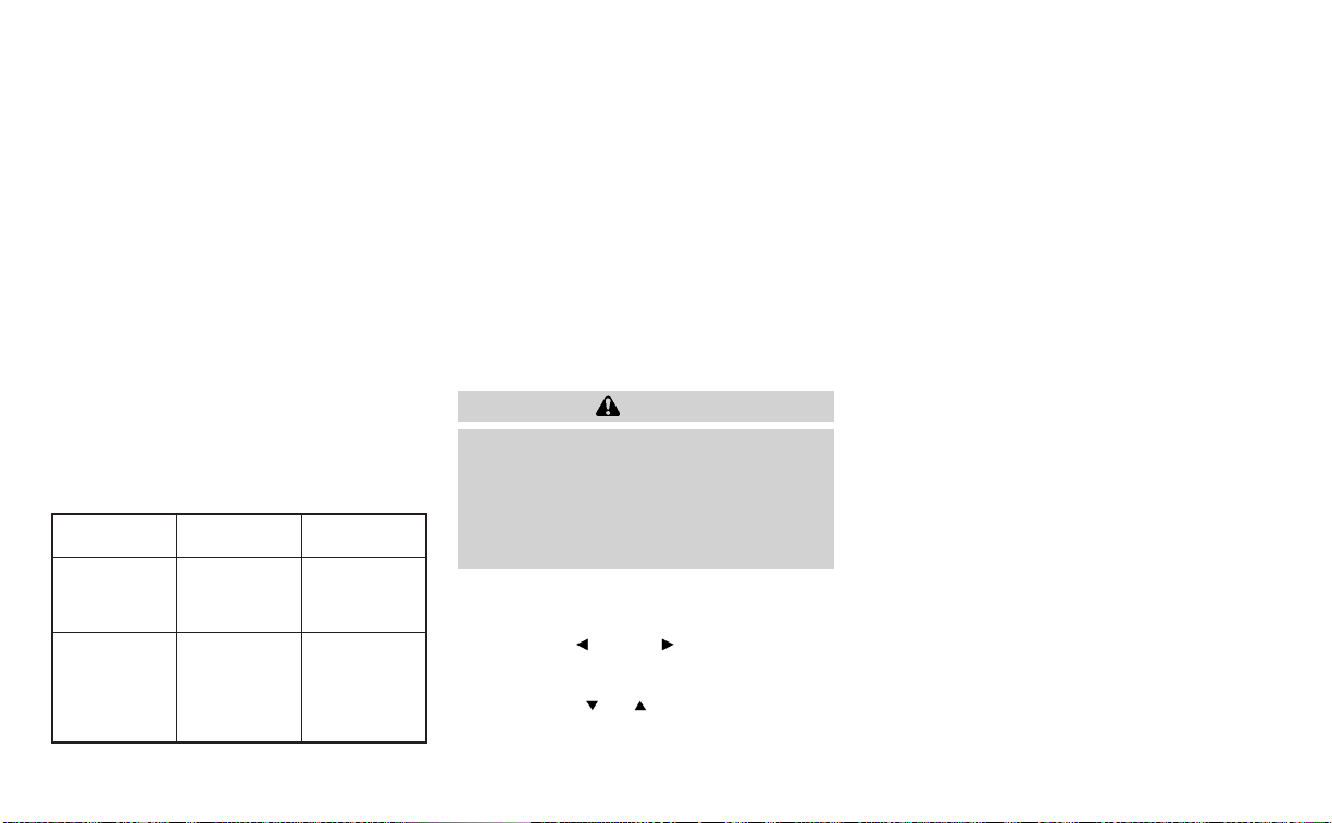
NOTE:
If you wish to reset all drive computer val-
ues at once, press and hold the OK button
for approximately 3 seconds until a reset
menu appears; and follow the instructions.
OIL CONTROL SYSTEM (if so
equipped)
The oil control system can be accessed in
the Maintenance portion of the vehicle in-
formation display settings.
Engine oil information informs the distance
to oil change. Never exceed one year or
7,500 miles (12000 km) between oil change
intervals for the 2.0L 4 cylinder (KR20DDET
engine model) or 10,000 miles (16,000 km)
between oil change intervals for the 2.5L 4
cylinder (PR25DD engine model).
Display when
ignition is ON
Display timing Action Re-
quired
Engine Oil Ser-
vice due in xxx
miles
Remaining oil
life is less than
940 miles (1500
km).
Plan to have
your vehicle
serviced.
Engine Oil Ser-
vice due
Remaining oil
lifeis0miles(0
km).
Have your ve-
hicle serviced
within two
weeks or less
than 500 miles
(800 km).
The oil change interval cannot be adjusted
manually.
The distance to oil change interval is calcu-
lated depending on the driving conditions
and set automatically by the oil control sys-
tem. A reminder will be displayed when ap-
proaching the end of the service interval.
When the Factory Reset option is selected
in the vehicle information display, the oil
control system will also be reset to initial
value. Please change the engine oil when
Factory Reset is selected.
CAUTION
If the oil replacement indicator is dis-
played, change the engine oil within
two weeks or less than 500 miles (800
km).
Operating the vehicle with deteriorated
oil can damage the engine.
To reset oil control system:
1. Push ignition button to “ON” position.
2. Push the
and buttons located
on the steering wheel until “Settings” dis-
plays in the vehicle information display.
Use the
buttons to select
“Maintenance”. Then, press the OK
button.
3. Select the “Oil Control System” and press
the OK button.
4. Press the OK button according to the
reset instructions displayed at the bot-
tom of the “Oil Control System” mainte-
nance screen.
For additional information, see “Oil control
system” (P. 9-7).
SETTINGS
The setting mode allows you to change the
information displayed in the vehicle infor-
mation display. It also allows you to change
vehicle functions:
• VDC Setting
• Driver Assistance
• TPMS Setting
• Clock
• Vehicle Settings
• Maintenance
• Customize Display
• Unit/Language
• Key-Linked Settings (if so equipped)
• Factory Reset
Instruments and controls 2-35

VDC Setting
The VDC Setting menu allows the user to enable or disable the Vehicle Dynamic Control (VDC) system.
Menu item Explanation
System Allows the user to turn the VDC system on or off. For additional information, see “Vehicle Dynamic Control
(VDC) system” (P. 5-150).
Driver Assistance
The driver assistance menu allows the user to change the settings for driving, parking, and braking aids.
Some menu items shown below may not be equipped on your vehicle.
Menu item Explanation
Steering Assist Allows user to turn the Steering Assist of the ProPILOT Assist system on or off. For additional information, please
see “ProPILOT Assist” (P. 5-70).
Emergency Brake Displays available emergency braking options.
Front Allows user to turn the front emergency braking system on or off. For additional information, see “Automatic
Emergency Braking (AEB) with Pedestrian Detection” (P. 5-111) and “Intelligent Forward Collision Warning (I-FCW)”
(P. 5-123).
Rear Allows user to turn the rear emergency braking system on or off. For additional information, see “Rear Automatic
Braking (RAB)” (P. 5-104).
Lane Displays available lane options.
Lane Departure Warning Allows user to turn the Lane Departure Warning (LDW) system on or off. For additional information, see “Lane De-
parture Warning (LDW)” (P. 5-33).
Lane Departure Prevention Allows user to turn Intelligent Lane Intervention (I-LI) system on or off. For additional information, see “Intelligent
Lane Intervention (I-LI)” (P. 5-40).
Blind Spot Displays available blind spot options.
Blind Spot Warning Allows user to turn the Blind Spot Warning (BSW) system on or off. For additional information, see “Blind Spot
Warning (BSW)” (P. 5-46).
Side Indicator Brightness Allows user to change the brightness of the side indicator.
2-36 Instruments and controls

Menu item Explanation
Speed Limit Sign Allows user to turn the Speed Limit Sign recognition on or off. For additional information, see “Traffic Sign Recogni-
tion (TSR)” (P. 5-30).
Parking Aids Displays available parking aids.
Auto Show Sonar Allows user to auto display the sonar. For additional information, see “Rear Sonar System (RSS)” (P. 5-154).
Rear Allows user to turn the rear sonar on or off.
Distance Allows user to set the distance sensor range to Long/Medium/Short.
Volume Allows the user to set the parking sensor volume to High/Medium/Low.
Rear Cross Traffic Alert Allows user to turn the Rear Cross Traffic Alert (RCTA) system on or off. For additional information, see “Rear Cross
Traffic Alert (RCTA)” (P. 5-58).
Driver Attention Alert Allows user to turn the Intelligent Driver Alertness on or off. For additional information, see “Intelligent Driver Alert-
ness (I-DA)” (P. 5-138).
Timer Alert Allows user to set the timer alert.
Low Temperature Alert Allows user to turn the low temperature alert on or off.
Chassis Control Displays available chassis control options.
Active Trace Control Allows user to turn the Intelligent Trace Control system on or off. For additional information, see “Intelligent Trace
Control (I-TC)” (P. 5-153).
TPMS Setting
The TPMS settings menu allows the user to change the tire pressure units displayed in the vehicle information display.
Menu item Explanation
TPMS Setting Displays available TPMS settings.
Tire Pressure Unit Allows user to select the tire pressure units that will display in the vehicle information display.
Instruments and controls 2-37

Clock
Menu item Explanation
Clock Allows user to adjust the clock settings and time within the vehicle information display. Adjustments that can
be made include automatically setting the time, 12H/24H format, Daylight Saving Time, time zone, and manu-
ally setting the time.
The clock can also be set within the center display. For additional information, refer to the separate
NissanConnect® Owner’s Manual.
Vehicle Settings
The vehicle settings allow the user to change the settings for lights, wipers, locking, keys, and other vehicle settings.
Some menu items shown below may not be equipped on your vehicle.
Menu item Explanation
Lighting Displays the available lighting options.
Welcome Headlight Allows user to turn the welcome light on or off.
Auto Room Lamp Allows user to turn the auto room lamp on or off.
Accent Lighting Allows user to adjust the accent lighting brightness.
Auto Headlight Allows user to change when the auto headlights activate based on the exterior brightness.
Light Off Delay Allows user to change the length of time the exterior lights remain on.
Turn indicator Displays the available turn indicator options.
3 Flashes Allows user to turn the 3 flash pass feature on or off.
Continuous Allows user to adjust the continuous feature.
Locking Displays the available locking options.
Ext Door Switch Allows user to turn the exterior door switch on or off. When turned on, the request switch on the door is acti-
vated.
2-38 Instruments and controls

Menu item Explanation
Selective Unlock Allows user to turn selective unlock on or off. When turned on, only the driver’s door is unlocked after the door
unlock operation. When the door handle request switch on the driver’s or front passenger’s side door is
pushed to be unlocked, only the corresponding door is unlocked first. All the doors can be unlocked if the
door unlock operation is performed again within 5 seconds. When this item is turned off, all the doors will be
unlocked after the door unlock operation is performed once.
Auto Door Unlock Displays the auto door unlock options.
Shift to P Doors will unlock when the vehicle is shifted into P (Park).
IGN OFF Doors will unlock when the ignition is turned off.
OFF Doors will have to be manually unlocked.
Horn beeps on lock Allows user to turn answer back horn on or off. When turned on, the horn will chirp and the hazard indicators
will flash once when locking the vehicle with the Intelligent Key.
Wipers Displays the available wiper options.
Speed Dependent Allows user to turn wiper with speed on or off.
Driving Position Displays the available driving position options.
Exit Seat Slide Allows the user to turn the exit seat slide on or off. When turned on, this feature will move the driver’s seat
backward for an easy exit when the ignition is turned off and the driver’s door is opened. After getting into
the vehicle and placing the ignition switch in the ON position, the driver’s seat will move to the previous set
position. For additional information, see “Memory seat” (P. 3-31).
Rear Door Alert Displays the available Rear Door Alert options. For additional information, see “Rear Door Alert” (P. 2-65).
Horn & Alert When selected, the alert is displayed and horn sounds.
Alert Only When selected, only the alert is displayed.
OFF When selected, no alert or horn will be active.
Remote Engine Star t Allows user to turn the Remote Engine Start on or off. When turned on, the engine can be restarted remotely.
For additional information, see “Remote Engine Start” (P. 5-17).
Instruments and controls 2-39
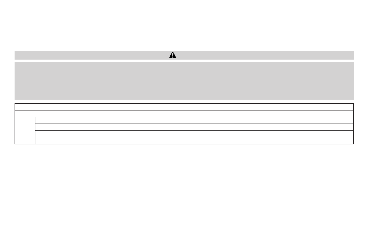
Maintenance
The maintenance menu allows the user to set reminders for various vehicle maintenance items.
WARNING
The tire replacement indicator is not a substitute for regular tire checks, including tire pressure checks. For additional informa-
tion, see “Changing wheels and tires” (P. 8-38). Many factors including tire inflation, alignment, driving habits and road conditions
affect tire wear and when tires should be replaced. Setting the tire replacement indicator for a certain driving distance does not
mean your tires will last that long. Use the tire replacement indicator as a guide only and always perform regular tire checks.
Failure to perform regular tire checks, including tire pressure checks could result in tire failure. Serious vehicle damage could
occur and may lead to a collision, which could result in serious personal injury or death.
Menu item Explanation
Maintenance Displays various maintenance reminder options.
Oil Control System Allows user to reset the current interval. This should only be done after completing oil change maintenance.
Oil and Filter Allows user to set a reminder at a specific interval or reset the current one.
Tire Allows user to set a reminder at a specific interval or reset the current one.
Other Allows user to set a reminder at a specific interval or reset the current one.
2-40 Instruments and controls

Customize Display
The customize display menu allows the user to customize the information that appears in the vehicle information display.
Some menu items shown below may not be equipped on your vehicle.
Menu item Explanation
Main Menu Selection Displays available screens that can be shown in the vehicle information display.
Home Allows user to turn the home screen on or off in the vehicle information display.
Blank Allows user to turn the blank on or off in the vehicle information display.
Audio Allows user to turn the audio controls screen on or off in the vehicle information display.
Navigation Allows user to turn the navigation screen on or off in the vehicle information display.
Fuel Economy Allows user to turn the fuel economy screen on or off in the vehicle information display.
Chassis Control Allows user to turn the chassis control screen on or off in the vehicle information display.
Cruise Allows user to turn the cruise control screen on or off in the vehicle information display.
Speed Limit Sign Allows user to turn the speed limit sign screen on or off in the vehicle information display.
TPMS Allows user to turn the TPMS screen on or off in the vehicle information display.
Variable Compression Turbo Allows user to turn the Variable Compression Turbo screen on or off in the vehicle information display.
Speed Allows user to turn the speedometer screen on or off in the vehicle information display.
Drive Computer Allows user to turn the drive computer screen on or off in the vehicle information display.
Auto Turn Notification Displays the available auto turn notification settings.
Alerts Allows user to turn the auto turn notification alerts on or off.
Cruise Screen Transition Allows user to turn the cruise screen transition on or off.
Welcome Effect Displays the available welcome effect settings.
Gauges Allows user to turn the gauges effect on or off.
Animation Allows user to turn the animation effect on or off.
Light/Wiper Guidance Displays the available light and wiper guidance settings.
Lights mode guidance Allows user to turn the light mode guidance on or off.
Wiper mode guidance Allows user to turn the wiper mode guidance on or off.
Instruments and controls 2-41

Unit/Language
The unit/language menu allows the user to change the units shown in the vehicle information display.
Menu item Explanation
Mileage/Fuel Displays the available mileage/fuel display units and allows user to select preferred unit for display.
Tire Pressure Allows user to select the tire pressure display units. Changing the tire pressure units will also change the
units displayed for the Variable Compression Turbo (if so equipped).
Temperature Allows user to select the temperature display units.
Language Displays the available language options and allows user to select preferred language for display.
Key-Linked Settings (if so equipped)
Menu item Explanation
Key-Linked Settings Allows user to turn the Key-Linked Settings on or off. For additional information, see “Memory storage func-
tion” (P. 3-31).
Factory Reset
The factory reset menu allows the user to restore the vehicle information display settings to factory status.
Menu item Explanation
Factory Reset
Allows user to reset the vehicle information display settings to the original factory settings. Once selected,
the user can confirm or cancel the reset.
2-42 Instruments and controls

VEHICLE INFORMATION DISPLAY
WARNINGS AND INDICATORS
The following messages may appear in
your vehicle information display.
Place the key near the start
switch
This indicator appears when the battery of
the Intelligent Key is low and when the In-
telligent Key system and the vehicle are not
communicating normally.
If this appears, touch the ignition switch
with the Intelligent Key while depressing
the brake pedal. For additional information,
see “NISSAN Intelligent Key® batter y dis-
charge” (P. 5-15).
Key Battery Low
This indicator appears when the Intelligent
Key battery is running out of power.
If this indicator appears, replace the bat-
tery with a new one. For additional infor-
mation, see “Battery replacement” (P. 8-23).
Key ID Incorrect
This warning appears when the ignition
switch is placed from the OFF position and
the Intelligent Key is not recognized by the
system. You cannot start the engine with
an unregistered key.
For additional information, see “NISSAN In-
telligent Key®” (P. 3-7).
Key System Error: See
Owner’s Manual
After the ignition switch is placed in the ON
position, this warning appears for a period
of time and then turns off.
The Key System Error message warns of a
malfunction with the Intelligent Key sys-
tem. If the warning appears while the en-
gine is stopped, it may be impossible to
start the engine.
If the warning appears while the engine is
running, you can drive the vehicle. However,
in these cases, have the system checked. It
is recommended that you visit a NISSAN
dealer for this service.
No Key Detected
This warning appears when the Intelligent
Key is left outside the vehicle with the igni-
tion switch in the ON position. Make sure
the Intelligent Key is inside the vehicle.
For additional information, see “NISSAN In-
telligent Key®” (P. 3-7).
Brightness indicator
This indicator appears when the vehicle
information display screen brightness is
being adjusted.
Chassis Control System Error: See
Owner’s Manual
This warning appears if there is an error in
the Automatic Brake Hold system. Have the
system checked. It is recommended that
you visit a NISSAN dealer for this service. For
additional information, see “Chassis con-
trol” (P. 5-153) or “Automatic brake hold”
(P. 5-27).
Rear Door Alert is activated
When the system is enabled, this message
appears when the Rear Door Alert system
is active and can remind the driver to check
the back seat.
Instruments and controls 2-43

• Using the steering wheel switch, a driver
can select “Dismiss Message” to clear the
display for a period of time. If no selection
is made, this message automatically
turns off after a period of time.
• Using the steering wheel switch, a driver
can select “Disable Alert” to disable the
horn alert for the remainder of the cur-
rent trip.
WARNING
Selecting “Dismiss Message” during a
stop within a trip temporarily dis-
misses the message for that stop with-
out turning the system off. Alerts can
be provided for other stops during the
trip. Selecting “Disable Alert” turns off
the Rear Door Alert system for the re-
mainder of a trip and no audible alert
will be provided.
NOTE:
This system is disabled until a driver en-
ables it using the vehicle information
display. For additional information, see
“How to use the vehicle information dis-
play” (P. 2-34).
For additional information, see “Rear Door
Alert” (P. 2-65).
Check Rear Seat For All Articles
When the system is enabled, this message
appears when the vehicle comes to a com-
plete stop, the vehicle is transitioned from
the D (Drive) position to P (Park) position,
and the driver exits the vehicle. This mes-
sage alerts the driver, after a period of time,
to check for items in the rear seat after the
audible alert has been provided.
NOTE:
This system is disabled until a driver en-
ables it using the vehicle information
display. For additional information, see
“How to use the vehicle information dis-
play” (P. 2-34).
For additional information, see “Rear Door
Alert” (P. 2-65).
Door/Trunk Open
This warning appears when a door or the
trunk has been opened.
Drive sport mode indicator
A small “S” appears to the right of the Trans-
mission Shift Position indicator in the ve-
hicle information display when the drive
sport mode is engaged.
Activate the drive sport mode by pushing
the switch on the shift lever while the shift
lever is in the D (Drive) position.
For additional information, see “Driving the
vehicle” (P. 5-18 ).
Engine Oil Service due in – –
– miles
This distance to oil change is displayed if
the distance to oil change is less than 62
miles (100 km).
Headlight System Error: See Owner’s
Manual
This warning appears when there is an er-
ror with the system. For additional informa-
tion, see “Headlight and turn signal switch”
(P. 2-55).
Loose Fuel Cap
This warning appears when the fuel-filler
cap is not tightened correctly after the ve-
hicle has been refueled. For additional in-
formation, see “Fuel-filler cap” (P. 3-25).
2-44 Instruments and controls

Low Fuel
This warning appears when the fuel level in
the fuel tank is getting low. Refuel as soon
as it is convenient, preferably before the
fuel gauge reaches 0 (Empty). There will be
a small reserve of fuel in the tank when
the fuel gauge needle reaches 0 (Empty).
Low outside temperature
indicator
This indicator appears if the outside tem-
perature is below 37°F (3°C). The tempera-
ture can be changed to display in Fahren-
heit or Celsius. For additional information,
see “Unit” (P. 2-26).
Low Washer Fluid
This warning appears when the
windshield-washer fluid is at a low level.
Add windshield-washer fluid as necessary.
For additional information, see
“Windshield-washer fluid” (P. 8-13).
Power will turn off to save the battery
This message appears after a period of
time if the ignition switch is in the AUTO
ACC or the ON position and if the vehicle is
in P (Park). For additional information, see
“Push-button ignition switch positions”
(P. 5-14).
Power turned off to save the battery
This message appears after the ignition
switch is automatically turned off. For addi-
tional information, see “Push-button igni-
tion switch positions” (P. 5-14).
Press Brake Pedal
This message may appear in the following
situations:
• The driver tries to release the electronic
parking brake manually without depress-
ing the brake pedal.
• The vehicle is stopped on a steep hill; and
there is a possibility of moving back-
wards, even if the electronic parking
brake is applied.
• The vehicle moves while the automatic
brake hold is activated.
For additional information, see “Electronic
parking brake” (P. 5-25).
Push brake and start
switch to drive
This indicator appears when the shift lever
is in the P (Park) position and the vehicle
has not been started. Start the engine by
pushing the ignition switch with the brake
pedal depressed. You can start the engine
from any position of the ignition switch.
This message also appears when the ve-
hicle has been started using the Remote
Engine Start function (if so equipped). Push
the ignition switch with the brake pedal
depressed to place the ignition switch in
the ON position. For additional information,
see “Remote Engine Start” (P. 3-19).
Push Ignition to OFF
After the Push Ignition to OFF warning ap-
pears, the warning will appear if the ignition
switch is placed in the AUTO ACC position
when the shift lever is moved to the P (Park)
position.
To turn the warning off, place the ignition
switch in the ON position and then in the
LOCK position.
Release Parking Brake
This warning appears when the parking
brake is set and the vehicle is driven.
Reminder: Turn OFF
Headlights
This warning appears when the headlights
are left in the ON position when exiting the
vehicle. Place the headlight switch in the
OFF or AUTO position. For additional infor-
mation, see “Headlight and turn signal
switch” (P. 2-55)
Instruments and controls 2-45

Shift to Park
This warning appears when the ignition
switch is in the AUTO ACC or OFF position
and the shift lever is not in the P (Park)
position. Also, a chime sounds when the
ignition switch is in the AUTO ACC or OFF
position.
If this warning appears, move the shift lever
to the P (Park) position and start the engine.
Shipping Mode On Push Storage Fuse
This warning may appear if the extended
storage switch is not pushed in. When this
warning appears, push in the extended
storage switch to turn off the warning. For
additional information, see “Extended stor-
age switch” (P. 2-68).
Timer Alert Time for a
break?
This message appears when the set time
is reached. This time can be set up to six
hours. For additional information, see
“Driver Assistance” (P. 2-36)
Tire Pressure Low - Add Air
This warning appears when the low tire
pressure warning light in the meter illumi-
nates and low tire pressure is detected. The
warning appears each time the ignition
switch is placed in the ON position as long
as the low tire pressure warning light re-
mains illuminated. If this warning appears,
stop the vehicle and adjust the tire pres-
sures of all four tires to the recommended
COLD tire pressure shown on the Tire and
Loading Information label. For additional
information, see “Low tire pressure warning
light” (P. 2-13) and “Tire Pressure Monitoring
System (TPMS)” (P. 5-5).
Transmission Shift Position
indicator
This indicator shows the transmission shift
position.
AWD Error: See Owner’s
Manual
This warning appears when the All-Wheel
Drive (AWD) system is not functioning prop-
erly while the engine is running.
AWD High Temp. Stop
Vehicle
This warning may appear while trying to
free a stuck vehicle due to increased oil
temperature. The driving mode may
change to 2-Wheel Drive (2WD). If this warn-
ing is displayed, stop the vehicle with the
engine idling, as soon as it is safe to do so.
Then if the warning turns off, you can con-
tinue driving.
Tire Size Incorrect See
Owner’s Manual
This warning may appear if there is a large
difference between the diameters of the
front and rear wheels. Pull off the road in a
safe area, with the engine idling. Check that
all the tire sizes are the same, that the tire
pressure is correct and that the tires are
not excessively worn.
CVT (AT) Malfunction
Service now
This warning appears when there is a
problem with the CVT system. If this warn-
ing appears, have the system checked. It is
recommended that you visit a NISSAN
dealer for this service.
2-46 Instruments and controls

CVT (AT) hot Power reduced
This transmission has a high fluid tem-
perature protection mode. If the fluid tem-
perature becomes too high (for example,
climbing steep grades in high tempera-
tures with heavy loads, such as when tow-
ing a trailer), engine power and, under
some conditions, vehicle speed will be de-
creased automatically to reduce the
chance of transmission damage. Vehicle
speed can be controlled with the accelera-
tor pedal, but the engine and vehicle speed
may be reduced.
WARNING
When the high fluid temperature pro-
tection mode operation occurs, vehicle
speed may be gradually reduced. The
reduced speed may be lower than
other traffic, which could increase the
chance of a collision. Be especially
careful when driving. If necessary, pull
to the side of the road at a safe place
and allow the transmission to return to
normal operation; or have it repaired if
necessary.
Automatic Emergency
Braking (AEB) with
Pedestrian Detection
emergency warning
indicator
This indicator appears along, with an au-
dible warning, when the system detects
the possibility of a forward collision.
For additional information, see “Automatic
Emergency Braking (AEB) with Pedestrian
Detection” (P. 5-111).
Blind Spot Warning (BSW)
indicator
This indicator appears when the BSW sys-
tem is engaged.
For additional information, see “Blind Spot
Warning (BSW)” (P. 5-46).
Cruise control indicator
This indicator shows the cruise control sys-
tem status.
When cruise control is activated, a green
circle will appear to indicate it is set. The
vehicle information display will also display
the speed the cruise control was set at. If
you accelerate past the set speed, the
speed will blink until you either cancel
cruise control or go back to the set speed. If
cruise control is on and canceled, the
speed will be displayed to show the speed
the vehicle will return to if the resume but-
ton is activated.
Currently not available
This message may appear when the ProPI-
LOT Assist system or the Intelligent Lane
Intervention (I-LI) system is engaged.
Under the following conditions, the ProPI-
LOT Assist or the Intelligent Lane Interven-
tion (I-LI) system is automatically canceled:
• When the VDC system is turned off
The above system cannot be used in some
situations (VDC operates, wheel slip and
VDC system is off.)
Driver Attention Alert
Malfunction
This warning appears when the Intelligent
Driver Alertness (I-DA) system is not func-
tioning properly. For additional information,
see “Intelligent Driver Alertness (I-DA)”
(P. 5-138).
Driver Attention Alert—
TakeaBreak?
This alert appears when the system has
detected that the driver may be displaying
fatigue or a lack of attention.
Instruments and controls 2-47

Forward Driving Aids temporarily
disabled Front Sensor blocked See
Owner’s Manual
This message appears when the front ra-
dar sensor may be obstructed due to:
• mud, dirt, snow, ice, etc.
• inclement weather (rain, fog, snow, etc.).
All forward driving aids are temporarily dis-
abled until the system detects that the
front radar sensor is no longer obstructed.
For additional information, see:
• Automatic Emergency Braking (AEB) with
Pedestrian Detection (P. 5-111)
• ProPILOT Assist (P. 5-70)
• Intelligent Forward Collision Warning (I-
FCW ) (P. 5-123)
Intelligent Lane
Intervention (I-LI) indicator
This indicator shows when the I-LI system
is engaged.
For additional information, see “Intelligent
Lane Intervention (I-LI)” (P. 5-40).
Lane Departure Warning
(LDW) indicator
This indicator shows when the LDW system
is engaged.
For additional information, see “Lane De-
parture Warning (LDW)” (P. 5-33) and “Intelli-
gent Lane Intervention (I-LI)” (P. 5-40).
Malfunction
This warning appears when one or more of
the following systems (if so equipped) is
not functioning properly:
• Automatic Emergency Braking (AEB) with
Pedestrian Detection
• Intelligent Forward Collision Warning
(I-FCW )
If one or more of these warning appears,
have the system checked. It is recom-
mended that you visit a NISSAN dealer for
this service.
For additional information, see “Automatic
Emergency Braking (AEB) with Pedestrian
Detection” (P. 5-111) or “Intelligent Forward
Collision Warning (I-FCW) (P. 5-123).
Malfunction: See Owner’s Manual
This warning appears when one or more of
the following systems (if so equipped) is
not functioning properly:
• Traffic Sign Recognition (TSR)
• Rear Automatic Braking (RAB)
If one or more of these warning appears,
have the system checked. It is recom-
mended that you visit a NISSAN dealer for
this service.
Not Available Parking Brake On
This message may appear when the ProPI-
LOT Assist system is engaged.
Under the following condition, the ProPILOT
Assist system is automatically canceled:
• The electronic parking brake is applied.
The above system cannot be used when
the electronic parking is activated.
For additional information, see "ProPILOT
Assist (P. 5-70) and “Parking brake” (P. 5-24).
Not Available Poor Road Conditions
This message may appear when the ProPI-
LOT Assist system or the Intelligent Lane
Intervention (I-LI) system is engaged.
2-48 Instruments and controls

Under the following conditions, the ProPI-
LOT Assist system or the Intelligent Lane
Intervention (I-LI) system is automatically
canceled:
• When the VDC system is turned off
The above system cannot be used in some
situations (VDC operates, wheel slip and
VDC system is off.)
Not Available Seat Belt Not Fastened
This message may appear when the ProPI-
LOT Assist system is engaged.
Under the following condition, the ProPILOT
Assist system is automatically canceled:
• When the driver’s seat belt is not fastened
The above system cannot be used when
the driver’s seat belt is not fastened.
Not Available System Malfunction
This warning appears when one or more of
the following systems (if so equipped) is
not functioning properly.
• ProPILOT
• Blind Spot Warning (BSW)
• Lane Departure Warning (LDW )
• Intelligent Lane Intervention (I-LI)
If one or more of these warnings appear,
have the system checked. It is recom-
mended that you visit a NISSAN dealer for
this service.
For additional information, see ProPILOT
Assist” (P. 5-70), “Blind Spot Warning (BSW)”
(P. 5-46), “Lane Departure Warning (LDW)”
(P. 5-33) or “Intelligent Lane Intervention (I-
LI)” (P. 5-40).
Parking Sensor Error: See Owner’s
Manual
This warning appears when there is an er-
ror with the system. For additional informa-
tion, see “Rear Sonar System (RSS)” (P. 5-155).
ProPILOT Assist indicators
These indicators show the ProPILOT Assist
system status. The status is shown by
color. For additional information, see “Pro-
PILOT Assist” (P. 5-70).
Rear Automatic Braking
(RAB) indicator
This indicator appears to indicate the sta-
tus of the Rear Automatic Braking (RAB)
system. For additional information, see
“Rear Automatic Braking (RAB)” (P. 5-104).
Speed Limit Sign indicator
This message may appear when the Traffic
Sign Recognition system is engaged.
For additional information, see “Traffic Sign
Recognition (TSR)” (P. 5-30).
Steering Assist Alert
This message may appear when the Steer-
ing Assist system is engaged.
It will be displayed under the following
condition:
• When not holding the steering wheel or
when there is no steering wheel
operation
Please hold on the steering wheel immedi-
ately. When the steering operation is de-
tected, the warning turns off and the steer-
ing assist function is automatically
restored.
Steering Assist indicator
This indicator appears when the Steering
Assist system is engaged.
For additional information, see “ProPILOT
Assist” (P. 5-70).
Instruments and controls 2-49

Unavailable: High Cabin Temperature
This message appears when the camera
detects an interior temperature of more
than 104°F (40°C). For additional informa-
tion, see “Automatic Emergency Braking
(AEB) with Pedestrian Detection” (P. 5-111),
“ProPILOT Assist” (P. 5-70), “Intelligent Lane
Intervention (I-LI)” (P. 5-96), “Lane Departure
Warning (LDW)” (P. 5-33) or “Traffic Sign Rec-
ognition (TSR) . (P. 5-30).
Unavailable: Side Radar Obstruction
This message appears when the Blind
Spot Warning (BSW)/Rear Cross Traffic Alert
(RCTA) systems become unavailable be-
cause a radar blockage is detected. For
additional information, see “Blind Spot
Warning (BSW)” (P. 5-46) or “Rear Cross Traf-
fic Alert (RCTA)” (P. 5-58).
Vehicle ahead detection
indicator
This indicator shows when the following
systems are engaged and have detected a
vehicle:
• Automatic Emergency Braking (AEB) with
Pedestrian Detection
• Intelligent Forward Collision Warning
(I-FCW )
For additional information, see “Automatic
Emergency Braking (AEB) with Pedestrian
Detection” (P. 5-111) or “Intelligent Forward
Collision Warning (I-FCW)” (P. 5-123).
Your vehicle may have two types of security
systems:
• Vehicle security system
• NISSAN Vehicle Immobilizer System
VEHICLE SECURITY SYSTEM
The vehicle security system provides visual
and audible alarm signals if someone
opens the doors or trunk when the system
is armed. It is not, however, a motion detec-
tion type system that activates when a ve-
hicle is moved or when a vibration occurs.
The system helps deter vehicle theft but
cannot prevent it, nor can it prevent the
LIC0301
SECURITY SYSTEMS
2-50 Instruments and controls

theft of interior or exterior vehicle compo-
nents in all situations. Always secure your
vehicle even if parking for a brief period.
Never leave your keys in the vehicle, and
always lock the vehicle when unattended.
Be aware of your surroundings, and park in
secure, well-lit areas whenever possible.
Many devices offering additional protec-
tion, such as component locks, identifica-
tion markers, and tracking systems, are
available at auto supply stores and spe-
cialty shops. A NISSAN dealer may also offer
such equipment. Check with your insur-
ance company to see if you may be eligible
for discounts for various theft protection
features.
How to arm the vehicle security
system
1. Close all windows and the moonroof.
The system can be armed even if the
windows and moonroof (if so
equipped) are open.
2. Remove the Intelligent Key from the
vehicle.
3. Close all doors, hood and trunk. Lock all
doors. The doors can be locked with the
Intelligent Key, door handle request
switch, or power door lock switch..
4. Confirm that the
indicator light
comes on. The
indicator stays
illuminated for a period of time indicat-
ing that the system is in the pre-armed
phase.
The
indicator light will blink every
3 seconds once the security system is
armed.
If during the pre-armed phase one of
the following occurs, the system will not
arm:
• Any door is unlocked with the Intelligent
Key or door request switch.
• The ignition switch is placed in the AUTO
ACC or ON position.
• Even when the driver and/or passen-
gers are in the vehicle, the system will
activate when all the doors, hood and
trunk are locked with the ignition
switch placed in the LOCK position.
When placing the ignition switch in the
AUTO ACC or ON position, the system
will be released.
Vehicle security system activation
The vehicle security system will give the
following alarm:
• The headlights blink and the horn sounds
intermittently.
• The alarm automatically turns off after a
period of time. However, the alarm reacti-
vates if the vehicle is tampered with
again. The alarm can be shut off by press-
ing the
button on the Intelligent Key.
The alarm is activated by:
• opening the door or trunk without using
Intelligent Key (even if the door is un-
locked by releasing the door inside lock
knob switch).
How to stop an activated alarm
The alarm stops only by unlocking a door
by pressing the
button on the Intelli-
gent Key or pushing the request switch on
the driver's or passenger's door with the
Intelligent Key in range of the door handle.
Instruments and controls 2-51

NISSAN VEHICLE IMMOBILIZER
SYSTEM
The NISSAN Vehicle Immobilizer System
will not allow the engine to start without
the use of a registered key.
If the engine fails to start using a registered
key (for example, when interference is
caused by another registered key, an auto-
mated toll road device or automatic pay-
ment device on the key ring), restart the
engine using the following procedures:
1. Leave the ignition switch placed in the
ON position for approximately 5
seconds.
2. Place the ignition switch in the OFF or
LOCK position, and wait approximately
10 seconds.
3. Repeat steps 1 and 2.
4. Restart the engine while holding the de-
vice (which may have caused the inter-
ference) separate from the registered
key.
If the no start condition re-occurs, NISSAN
recommends placing the registered key on
a separate key ring to avoid interference
from other devices.
FCC Notice:
For USA:
This device complies with part 15 of the
FCC Rules. Operation is subject to the fol-
lowing two conditions: (1) This device
may not cause harmful interference, and
(2) this device must accept any interfer-
ence received, including interference
that may cause undesired operation.
NOTE:
Changes or modifications not expressly
approved by the party responsible for
compliance could void the user's author-
ity to operate the equipment.
For Canada:
This device contains licence-exempt
transmitter(s)/receiver(s) that comply
with Innovation, Science and Economic
Development Canada’s licence-exempt
RSS(s). Operation is subject to the fol-
lowing two conditions: (1) This device
may not cause interference (2) This de-
vice must accept any interference, in-
cluding interference that may cause un-
desired operation of the device.
Security indicator light
The security indicator light blinks whenever
the ignition switch is placed in the OFF,
LOCK or AUTO ACC position.
This function indicates the NISSAN Vehicle
Immobilizer System is operational.
If the NISSAN Vehicle Immobilizer System is
malfunctioning, the light will remain on
while the ignition switch is placed in the ON
position.
LIC0474
2-52 Instruments and controls

If the light still remains on and/or the
engine will not start, seek service for the
NISSAN Vehicle Immobilizer System as
soon as possible. Please bring all regis-
tered keys that you have. It is recom-
mended that you visit a NISSAN dealer
for this service.
SWITCH OPERATION
WARNING
In freezing temperatures the washer
solution may freeze on the windshield
and obscure your vision which may
lead to an accident. Warm the wind-
shield with the defroster before you
wash the windshield.
CAUTION
• Do not operate the washer continu-
ously for more than 30 seconds.
• Do not operate the washer if the
windshield-washer fluid reservoir is
empty.
• Do not fill the windshield-washer
fluid reservoir with windshield-
washer fluid concentrates at full
strength. Some methyl alcohol
based windshield-washer fluid con-
centrates may permanently stain the
grille if spilled while filling the
windshield-washer fluid reservoir.
• Pre-mix windshield-washer fluid
concentrates with water to the
manufacturer's recommended lev-
els before pouring the fluid into the
windshield-washer fluid reservoir.
Do not use the windshield-washer
fluid reservoir to mix the windshield-
washer fluid concentrate and water.
NOTE:
If the windshield wiper operation is in-
terrupted by snow or ice, the wiper may
stop moving to protect its motor. If this
occurs, turn the wiper switch to the OFF
position and remove the snow or ice that
is on and around the wiper arms. In ap-
proximately 1 minute, turn the switch on
again to operate the wiper.
LIC4238
WIPER AND WASHER SWITCH
Instruments and controls 2-53

The windshield wiper and washer operates
when the ignition switch is placed in the ON
position.
Push the lever down to operate the wiper
at the following speed:
䊊
1
Intermittent — intermittent operation
can be adjusted by turning the knob
toward
O
A
(faster) or
O
B
(slower).
䊊
2
Low — continuous low speed operation
䊊
3
High — continuous high speed
operation
Push the lever up
O
4
to have one sweep
operation (MIST) of the wiper.
Pull the lever toward you
O
5
to operate the
washer. The wiper will also operate several
times.
NOTE:
The Wiper with Speed and Wiper Guid-
ance features may be disabled. For addi-
tional information, see “Vehicle informa-
tion display-5 inch (13 cm) Type A”
(P. 2-18) or “Vehicle information display-7
inch (18 cm) Type B” (P. 2-33).
To defrost the rear window glass and out-
side mirrors (if so equipped), place the igni-
tion switch in the ON position and push the
rear window defroster switch on. The rear
window defroster indicator light on the
switch comes on. Push the switch again to
turn the defroster off.
The rear window defroster automatically
turns off after approximately 15 minutes.
CAUTION
When cleaning the inner side of the rear
window, be careful not to scratch or
damage the rear window defroster.
NOTE:
The top and bottom few rows of wires on
the rear window are not part of the rear
window defroster system. These wires
make up the antenna for the audio
system.
LIC4039
REAR WINDOW AND OUTSIDE
MIRROR (if so equipped)
DEFROSTER SWITCH
2-54 Instruments and controls

HEADLIGHT CONTROL SWITCH
Lighting
䊊
1
Rotate the switch to the position,
and the front parking, tail, license plate,
and instrument panel lights will come
on. The
will illuminate in the meter.
䊊
2
Rotate the switch to the position,
and the headlights will come on and all
the other lights remain on.
NOTE:
The Light Guidance feature may be dis-
abled. For additional information, see
“Vehicle information display-5 inch (13
cm) Type A” (P. 2-18) or “Vehicle informa-
tion display-7 inch (18 cm) Type B”
(P. 2-33).
CAUTION
Use the headlights with the engine run-
ning to avoid discharging the vehicle
battery.
LIC2634
Type A (if so equipped)
LIC2635
Type B (if so equipped)
LIC4237
Type C (if so equipped)
HEADLIGHT AND TURN SIGNAL
SWITCH
Instruments and controls 2-55

Autolight system
The autolight system allows the headlights
to turn on and off automatically. The auto-
light system can:
• Turn on the headlights, front parking, tail,
license plate and instrument panel lights
automatically when it is dark.
• Turn off all the lights when it is light.
• Keep all the lights on for a period of time
after you place the ignition switch in the
OFF position and all doors are closed.
NOTE:
Autolight activation sensitivity and the
time delay for autolight shutoff can be
adjusted.
For additional information, see “Vehicle
information display-5 inch (13 cm) Type
A” (P. 2-18) or “Vehicle information
display-7 inch (18 cm) Type B” (P. 2-33).
To turn on the autolight system:
1. Turn the headlight switch to the AUTO
position
O
1
.
2. Place the ignition switch in the ON
position.
3. The autolight system automatically
turns the headlights on and off.
Initially, if the ignition switch is placed in the
OFF position and a door is opened and left
open, the headlights remain on for a period
of time. If another door is opened while the
headlights are on, then the timer is reset.
To turn the autolight system off, turn the
switch to the OFF (if so equipped),
,or
position.
The headlights will turn on automatically at
twilight or in rainy weather (when the wind-
shield wiper is operated continuously).
LIC4498
Type D (if so equipped)
LIC2636
2-56 Instruments and controls
If the ignition switch is pushed to the OFF
position and one of the doors is opened
and this condition is continued, the head-
lights remain on for 5 minutes.
Be sure you do not put anything on top
of the autolight sensor located in the top
side
O
1
of the instrument panel. The au-
tolight sensor controls the autolight; if it
is covered, the autolight sensor reacts as
if it is dark out and the headlights will
illuminate. If this occurs while parked
with the engine off and the ignition
switch placed in the ON position, your
vehicle's battery could become
discharged.
Headlight beam select
䊊
1
To select the high beam function, put
the headlight switch in the
posi-
tion and push the lever forward. The
high beam lights come on and the
light illuminates in the meter.
䊊
2
Pull the lever back to select the low
beam.
䊊
3
Pulling and releasing the lever flashes
the headlight high beams on and off.
LIC0836 LIC2637
Instruments and controls 2-57

High Beam Assist (if so equipped)
The High Beam Assist system will operate
when the vehicle is driven at speeds of ap-
proximately 25 mph (40 km/h) and above. If
an oncoming vehicle or leading vehicle ap-
pears in front of your vehicle when the
headlight high beam is on, the headlight
will be switched to the low beam
automatically.
WARNING
• The High Beam Assist system is a
convenience but it is not a substitute
for safe driving operation. The driver
should remain alert at all times, en-
sure safe driving practices and
switch the high beams and low beam
manually when necessary.
• The high beam or low beam may not
switch automatically under the fol-
lowing conditions. Switch the high
beam and low beam manually.
– During bad weather (rain, fog,
snow, wind, etc.).
– When a light source similar to a
headlight or tail light is in the vi-
cinity of the vehicle.
– When the headlights of the on-
coming vehicle or the leading ve-
hicle are turned off, when the color
of the light is affected due to for-
eign materials on the lights, or
when the light beam is out of
position.
– When there is a sudden, continu-
ous change in brightness.
– When driving on a road that
passes over rolling hills, or a road
that has level differences.
– When driving on a road with many
curves.
– When a sign or mirror-like surface
is reflecting intense light towards
the front of the vehicle.
– When the container, etc. being
towed by a leading vehicle is re-
flecting intense light.
– When a headlight on your vehicle
is damaged or dirty.
– When the vehicle is leaning at an
angle due to a punctured tire, be-
ing towed, etc.
• The timing of switching the low
beam and high beam may change
under the following situations.
– The brightness of the headlights
of the oncoming vehicle or leading
vehicle.
– The movement and direction of
the oncoming vehicle and the
leading vehicle.
– When only one light on the on-
coming vehicle or the leading ve-
hicle is illuminated.
– When the oncoming vehicle or the
leading vehicle is a two-wheeled
vehicle.
– Road conditions (incline, curve,
the road surface, etc.).
– The number of passengers and
the amount of luggage.
2-58 Instruments and controls

High Beam Assist operation
To activate the High Beam Assist system,
turn the headlight switch to the AUTO po-
sition
O
1
and push the lever forward
O
2
(high beam position). The High Beam
Assist indicator light in the meter will illumi-
nate while the headlights are turned on.
If the High Beam Assist indicator light does
not illuminate in the above condition, it may
indicate that the system is not functioning
properly. Have the system checked, it is
recommended that you visit a NISSAN
dealer for this service.
When the vehicle speed lowers to less than
approximately 16 mph (25 km/h), the head-
light uses the low beam.
To turn off the High Beam Assist system,
turn the headlight switch to the
posi-
tion or select the low beam position by
placing the lever in the N (Neutral) position.
Ambient image sensor maintenance
The ambient image sensor
O
A
for the High
Beam Assist system is located in front of
the inside mirror. To maintain the proper
operation of the high beam assist system
and prevent a system malfunction, be sure
to observe the following:
• Always keep the windshield clean.
• Do not attach a sticker (including trans-
parent material) or install an accessory
near the ambient image sensor.
• Do not strike or damage the areas
around the ambient image sensor. Do
not touch the sensor lens that is located
on the ambient image sensor.
LIC3696 LSD3502
Instruments and controls 2-59

If the ambient image sensor is damaged
due to an accident, it is recommended that
you visit a NISSAN dealer.
Battery saver system (if so
equipped)
If the ignition switch is placed in the OFF
position while the headlight switch is in the
or position, the headlights will
turn off after a period of time.
CAUTION
Even though the battery saver feature
automatically turns off the headlights
after a period of time, you should turn
the headlight switch to the OFF posi-
tion when the engine is not running to
avoid discharging the vehicle battery.
LED DAYTIME RUNNING LIGHTS
(DRL) SYSTEM (if so equipped)
The LED DRL automatically illuminate at
100% intensity when the engine is started
and the parking brake released. The LED
Day time Running Lights (DRL) operate with
the headlight switch in any position. When
you turn the headlight switch to the
position for full illumination, the LED DRL
illuminate at a lower intensity.
If the parking brake is applied before the
engine is started, the LED DRL do not illumi-
nate. The LED DRL illuminate when the
parking brake is released. The LED DRL will
remain on until the ignition switch is placed
in the OFF position.
At dusk, the headlights, interior controls
and switches will automatically illuminate if
the headlight switch is in the AUTO
position.
WARNING
When the LED DRL system is active, tail
lights on your vehicle are not on. It is
necessary at dusk to turn on your
headlights. Failure to do so could cause
an accident injuring yourself and
others.
INSTRUMENT BRIGHTNESS
CONTROL
Press the “+” button to increase the bright-
ness of instrument panel lights.
Press the “-” button to decrease the bright-
ness of instrument panel lights.
LIC3176
2-60 Instruments and controls

TURN SIGNAL SWITCH
Turn signal
䊊
1
Move the lever up or down to signal the
turning direction. When the turn is com-
pleted, the turn signal cancels
automatically.
Lane change signal
䊊
2
Move the lever up or down until the turn
signal begins to flash, but the lever
does not latch, to signal a lane change.
Hold the lever until the lane change is
completed.
Move the lever up or down until the turn
signal begins to flash, but the lever does
not latch, and release the lever. The turn
signal will automatically flash three times.
Choose the appropriate method to signal
a lane change based on road and traffic
conditions.
NOTE:
The 3 flash pass feature may be disabled.
For additional information, see “Vehicle
information display-5 inch (13 cm) Type
A” (P. 2-18) or “Vehicle information
display-7 inch (18 cm) Type B” (P. 2-33).
FOG LIGHT SWITCH (if so
equipped)
To turn the fog lights on, turn the headlight
switch to the
position, then turn the
fog light switch to the
position.
To turn the fog lights on with the headlight
switch in the AUTO position, the headlights
must be on, then turn the fog light switch to
the
position.
To turn the fog lights off, turn the fog light
switch to the OFF position.
LIC2638 LIC2639
Type A (if so equipped)
Instruments and controls 2-61

The headlights must be on and the low
beams selected for the fog lights to oper-
ate. The fog lights automatically turn off
when the high beam headlights are
selected.
To sound the horn, push near the horn icon
on the steering wheel.
WARNING
Do not disassemble the horn. Doing so
could affect proper operation of the
supplemental front air bag system.
Tampering with the supplemental
front air bag system may result in seri-
ous personal injury.
WARNING
Do not use or allow occupants to use
the seat heater if you or the occupants
cannot monitor elevated seat tem-
peratures or have an inability to feel
pain in body parts that contact the
seat. Use of the seat heater by such
people could result in serious injury.
LIC4500
Type B (if so equipped)
LIC3568 LIC3973
HORN HEATED SEAT SWITCHES (if so
equipped)
2-62 Instruments and controls

CAUTION
• The battery could run down if the
seat heater is operated while the en-
gine is not running.
• Do not use the seat heater for ex-
tended periods or when no one is us-
ing the seat.
• Do not put anything on the seat
which insulates heat, such as a blan-
ket, cushion, seat cover, etc. Other-
wise, the seat may become
overheated.
• Do not place anything hard or heavy
on the seat or pierce it with a pin or
similar object. This may result in
damage to the heater.
• Any liquid spilled on the heated seat
should be removed immediately with
a dry cloth.
• When cleaning the seat, never use
gasoline, benzine, thinner, or any
similar materials.
• If any malfunctions are found or the
heated seat does not operate, turn
the switch off and have the system
checked. It is recommended that you
visit a NISSAN dealer for this service.
The front seats are warmed by built-in
heaters.
1. Place the ignition switch in the ON
position.
2. Push the switch until either two lights
are illuminated for high setting, or one
light is illuminated for low setting.
The heater is controlled by a thermostat,
automatically turning the heater on and
off. The indicator light will remain on as
long as the switch is on.
3. When the seat is warmed or before you
leave the vehicle, be sure to push the
switch to turn it off.
Push the heated steering wheel switch to
warm the steering wheel after the ignition
switch is placed in the ON position. The
indicator light will come on.
If the surface temperature of the steering
wheel is below 68°F (20°C), the system will
heat the steering wheel and cycle off and
on to maintain a temperature above 68°F
(20°C). The indicator light will remain on as
long as the system is on.
Push the switch again to turn the heated
steering wheel system off manually. The
indicator light will go off.
LIC4030
HEATED STEERING WHEEL SWITCH (if
so equipped)
Instruments and controls 2-63

NOTE:
• Once activated, your heated steering
wheel will automatically turn on and
off to maintain a temperature above
68°F (20°C).
• When the temperature of the steering
wheel is above 122°F (50°C) and the
heated steering wheel switch is turned
on, the system will not heat the steer-
ing wheel. This does not indicate a
malfunction.
The Steering Assist switch is used to en-
able and disable the Steering Assist sys-
tem that is activated using the settings
menu of the vehicle information display.
The Steering Assist system controls the
steering system, when ProPILOT Assist is
engaged, to help keep your vehicle near
the center of the lane when driving. For
additional information, see ”ProPILOT As-
sist” (P. 5-70) and “Intelligent Lane Interven-
tion (I-LI)” (P. 5-40).
LIC4101
STEERING ASSIST SWITCH (for
vehicles with ProPILOT Assist) (if so
equipped)
2-64 Instruments and controls

The Emergency call (SOS) button is used in
combination with a NissanConnect® Ser-
vices subscription to call for assistance in
case of an emergency.
The Emergency call button is under a
cover. Press the cover once
O
1
. The cover
will drop down, exposing the Emergency
call button.
Pressing the button
O
2
will (with a paid
subscription) reach a response specialist
that will provide assistance based on the
situation described by the vehicle’s occu-
pant. For additional information, or to enroll
your vehicle, refer to www.NissanUSA.com/
connect or call 855–426–6628.
The Rear Door Alert system functions un-
der certain conditions to indicate there
may be an object or passenger in the rear
seat(s). Check the seat(s) before exiting the
vehicle.
The Rear Door Alert system is initially dis-
abled. The driver can enable the system
using the vehicle information display. For
additional information, see “Vehicle infor-
mation display warnings and indicators”
(P. 2-27 or 2-43).
When the system is enabled:
• The system is activated when a rear door
is opened and closed within 10 minutes of
the vehicle being driven. When the driver
door is closed and the system is acti-
vated, a visual message appears in the
vehicle information display. For additional
information, see “Rear Door Alert is acti-
vated (P. 2-27 or 2-43)
• If a rear door is opened and closed but
the vehicle is not driven within approxi-
mately 10 minutes, the system will not be
activated. A rear door must be opened
and closed and the car driven within 10
minutes for the system to activate.
LIC4213
EMERGENCY CALL (SOS) BUTTON (if
so equipped)
REAR DOOR ALERT
Instruments and controls 2-65

When the Rear Door Alert system is acti-
vated:
• When the driver puts the vehicle in the P
(Park) position, a notification message
appears in the vehicle information dis-
play with the options to “Dismiss Mes-
sage” or “Disable Alert” if desired.
• Select “Disable Alert” to temporarily
disable for that stop.
• No selection or ‘Dismiss Message” will
keep the alert enabled for that stop.
• If the alert is enabled when a driver exits
the vehicle, a message will appear in the
vehicle information display that states
“Check Back Seat For All Articles.”
If “Horn & Alert” setting is selected:
• An audible horn sound will occur after
a short time unless a rear door is
opened and closed within a short time
to deactivate the alert.
• If the doors are locked before the alert
is deactivated by opening a rear door,
the horn will sound.
• If the trunk is opened before a rear
door is opened, the horn will be de-
layed until after the trunk is closed.
NOTE:
If “Aler t Only” setting is selected, the
message alert will still be shown in the
vehicle information display but the horn
will not sound.
WARNING
• If the driver selects “Disable Alert”, no
audible alert will be provided regard-
less of rear door open/close status.
• There may be times when there is an
object or passenger in the rear
seat(s) but the audible alert does not
sound. For example, this may occur if
rear seat passengers enter or exit the
vehicle during a trip.
• The system does not directly detect
objects or passengers in the rear
seat(s). Instead, it can detect when a
rear door is opened and closed, indi-
cating that there may be something
in the rear seat(s).
NOTE:
There may be times when the horn
sounds but there are no objects or pas-
sengers in the rear seat(s).
For additional information, see “Rear Door
Alert is activated (P. 2-27 or 2-43)
2-66 Instruments and controls

The power outlet is for powering electrical
accessories such as cellular telephones. It
is rated at 12 volt, 120W (10A) maximum.
The power outlet is powered only when the
ignition switch is in the AUTO ACC or ON
position.
CAUTION
• The outlet and plug may be hot dur-
ing or immediately after use.
• Only certain power outlets are de-
signed for use with a cigarette lighter
unit. Do not use any other power out-
let for an accessory lighter. For addi-
tional information, it is recom-
mended that you visit a NISSAN
dealer.
• Do not use with accessories that ex-
ceed a 12 volt, 120W (10A) power draw.
• Do not use double adapters or more
than one electrical accessory.
• Use power outlets with the engine
running to avoid discharging the ve-
hicle battery.
• Avoid using power outlets when the
air conditioner, headlights, or rear
window defroster is on.
• Before inserting or disconnecting a
plug, be sure the electrical accessory
being used is turned OFF.
• Push the plug in as far as it will go. If
good contact is not made, the plug
may overheat or the internal tem-
perature fuse may open.
• When not in use, be sure to close the
cap. Do not allow water or any other
liquid to contact the outlet.
LIC3345
Instrument Panel
POWER OUTLET
Instruments and controls 2-67

The extended storage switch is used when
shipping the vehicle. It is located in the fuse
panel to the left of the steering wheel on
the instrument panel. If any electrical
equipment does not operate, ensure the
extended storage switch is pushed fully in
place, as shown.
LIC4040 LIC3266
Pulled position
LIC3268
Pushed position
EXTENDED STORAGE SWITCH
2-68 Instruments and controls

FRONT-DOOR POCKETS SEATBACK POCKETS (if so
equipped)
The seatback pockets may be located on
the back of the driver’s and/or passenger’s
seats. The pockets can be used to store
maps.
WARNING
To ensure proper operation of the driv-
er’s and/or front passenger's NISSAN
Advanced Air Bag System (if so
equipped), please observe the follow-
ing items:
• Do not allow a passenger in the rear
seat to push or pull on the seatback
pocket or head restraint/head rest.
• Do not place heavy loads heavier
than 9.1 lbs. (4 kg) on the seatback,
head restraint/head rest or in the
seatback pocket.
LIC4088 LIC1328
STORAGE
Instruments and controls 2-69

GLOVE BOX
Open the glove box by pulling the handle.
Use the master key when locking
O
1
or un-
locking
O
2
the glove box.
WARNING
Keep glove box lid closed while driving
to help prevent injury in an accident or
a sudden stop.
CONSOLE BOX
To open the console box, press in on the
lever
O
1
and raise the lid
O
2
.
To close, push the lid down until the lock
latches.
OVERHEAD SUNGLASSES
STORAGE
To open the sunglasses holder, push and
release.
Only store one pair of sunglasses in the
holder.
WARNING
Keep the sunglasses holder closed
while driving to avoid obstructing the
driver’s view and to help prevent an
accident.
LIC2300 LIC4091 LIC4034
2-70 Instruments and controls

CAUTION
• Do not use for anything other than
sunglasses.
• Do not leave sunglasses in the sun-
glasses holder while parking in direct
sunlight. The heat may damage the
sunglasses.
CUP HOLDERS
The rear center cup holders are located in
the rear fold-down armrest.
CAUTION
• Avoid abrupt starting and braking
when the cup holder is being used to
prevent spilling the drink. If the liquid
is hot, it can scald you or your
passenger.
• Use only soft cups in the cup holder.
Hard objects can injure you in an
accident.
LIC4032
Front
LIC2297
Rear
Instruments and controls 2-71

POWER WINDOWS
WARNING
• Make sure that all passengers have
their hands, etc., inside the vehicle
while it is in motion and before clos-
ing the windows. Use the window
lock switch to prevent unexpected
use of the power windows.
• To help avoid risk of injury or death
through unintended operation of the
vehicle and/or its systems, including
entrapment in windows or inadver-
tent door lock activation, do not
leave children, people who require
the assistance of others or pets unat-
tended in your vehicle. Additionally,
the temperature inside a closed ve-
hicle on a warm day can quickly be-
come high enough to cause a signifi-
cant risk of injury or death to people
and pets.
The power windows operate when the ig-
nition switch is placed in the ON position or
for a period of time after the ignition switch
is placed in the OFF position. If the driver's
or passenger's door is opened during this
period of time, the power to the windows is
canceled.
Driver's side power window
switch
The driver's side control panel is equipped
with switches to open or close all of the
windows.
To open a window, push the switch to the
detent and continue to hold down until the
desired window position is reached. To
close a window, pull the switch to the de-
tent and continue to hold up until the de-
sired window position is reached.
LIC3208
1. Window lock switch
2. Power door lock switch
3. Front passenger side switch
4. Right rear passenger side switch
5. Left rear passenger side switch
6. Driver’s side automatic switch
WINDOWS
2-72 Instruments and controls
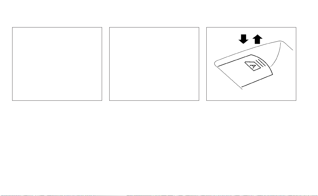
Front passenger's power window
switch
The passenger's window switch operates
only the corresponding passenger's win-
dow.To open the window partially, push the
switch down lightly until the desired win-
dow position is reached. To close the win-
dow, pull the switch up until the desired
window position is reached.
Rear power window switch
The rear power window switches open or
close only the corresponding windows. To
open the window, push the switch and hold
it down
O
1
. To close the window, pull the
switch up
O
2
.
Locking passengers' windows
When the window lock switch is depressed,
only the driver's side window can be
opened or closed. Push it again to cancel
the window lock function.
Automatic operation
To fully open a window equipped with au-
tomatic operation, push the window
switch down to the second detent and re-
lease it; it need not be held. The window
automatically opens all the way. To stop
the window, lift the switch up while the win-
dow is opening.
To fully close a window equipped with au-
tomatic operation, pull the switch up to the
second detent and release it; it need not be
held. The window automatically closes all
the way. To stop the window, push the
switch down while the window is closing.
LIC4228 LIC2663 LIC0410
Instruments and controls 2-73

Auto-reverse function
If the control unit detects something
caught in the window as it is closing, the
window will be immediately lowered.
The auto-reverse function can be acti-
vated when the window is closed by auto-
matic operation when the ignition switch is
placed in the ON position or for a period of
time after the ignition switch is placed in
the OFF position.
Depending on the environment or driv-
ing conditions, the auto-reverse func-
tion may be activated if an impact or
load similar to something being caught
in the window occurs.
WARNING
There are some small distances imme-
diately before the closed position
which cannot be detected. Make sure
that all passengers have their hands,
etc., inside the vehicle before closing
the window.
When power window switch does
not operate
If the power window automatic function
(closing only) does not operate properly,
perform the following procedure to initial-
ize the power window system:
1. Place the ignition switch in the ON
position.
2. Open the window more than halfway by
operating the power window switch.
3. Pull the power window switch and hold it
to close the window, and then hold the
switch more than 3 seconds after the
window is closed.
4. Release the power window switch. Op-
erate the window by the automatic
function to confirm the initialization is
complete.The power window automati-
cally opens or closes depending on if the
automatic down or up function is
selected.
5. Perform steps 2 through 4 above for
other windows.
If the power window function does not op-
erate properly after per forming the above
procedure have the system checked and
repaired. It is recommended that you visit a
NISSAN dealer for this service.
2-74 Instruments and controls

POWER MOONROOF
The moonroof will only operate when the
ignition switch is placed in the ON position.
The power moonroof is operational for a
period of time, even if the ignition switch is
placed in the AUTO ACC or OFF position. If
the driver's door or the front passenger's
door is opened during this period of time,
the power to the moonroof is canceled.
Sliding the moonroof
To fully open or close the moonroof, push
the switch to the open
O
1
or close
O
2
posi-
tion and release it; it need not be held. The
roof will automatically open or close all the
way. To stop the roof, push the switch once
more while it is opening or closing.
Tilting the moonroof
To tilt up, first close the moonroof, then
push the switch
O
3
and release it; it need
not be held. To tilt down the moonroof,
push the switch to the tilt down position
O
2
.
Resetting the moonroof switch
If the moonroof does not operate properly,
perform the following procedure to initial-
ize the moonroof operation system.
1. If the moonroof is open, close it fully by
repeatedly pushing the moonroof
switch to the closed position
O
2
.
2. Push and hold the switch to the closed
position
O
2
for approximately 15
seconds.
3. Release the switch after the moonroof
moves up, down, then back to the full tilt
up position.
4. Push and hold the switch to the closed
position
O
2
.
5. Release the switch after the moonroof
completes one full cycle from the tilt up
position to the closed position, then to
the open position, and again to the fully
closed position.
6. Check if the moonroof switch operates
normally.
If the moonroof does not operate properly
after performing the procedure above,
have your vehicle serviced. It is recom-
mended that you visit a NISSAN dealer for
this service.
Auto-reverse function (when
closing or tilting down the
moonroof)
The auto-reverse function can be acti-
vated when the moonroof is closed or
tilted down by automatic operation when
the ignition switch is placed in the ON po-
sition or for a period of time after the igni-
tion switch is placed in the OFF position.
Depending on the environment or driv-
ing conditions, the auto-reverse func-
tion may be activated if an impact or
load similar to something being caught
in the moonroof occurs.
LIC4249
MOONROOF (if so equipped)
Instruments and controls 2-75

WARNING
There are some small distances imme-
diately before the closed position
which cannot be detected. Make sure
that all passengers have their hands,
etc., inside the vehicle before closing
the moonroof.
When closing
If the control unit detects something
caught in the moonroof as it moves to the
front, the moonroof will immediately open
backward.
When tilting down
If the control unit detects something
caught in the moonroof as it tilts down, the
moonroof will immediately tilt up.
If the auto-reverse function malfunctions
and repeats opening or tilting up the
moonroof, keep pushing the tilt down
switch within 5 seconds after it happens;
the moonroof will fully close gradually.
Make sure nothing is caught in the
moonroof.
WARNING
• In an accident you could be thrown
from the vehicle through an open
moonroof. Always use seat belts and
child restraints.
• Do not allow anyone to stand up or
extend any portion of their body out
of the moonroof opening while the
vehicle is in motion or while the
moonroof is closing.
CAUTION
• Remove water drops, snow, ice or
sand from the moonroof before
opening.
• Do not place heavy objects on the
moonroof or surrounding area.
Sunshade
Open and close the sunshade by sliding it
forward or backward.
If the moonroof does not close
Have your moonroof checked and re-
paired. It is recommended that you visit a
NISSAN dealer for this service.
䊊
1
The interior light can be turned ON re-
gardless of door position. The light will
go off after a period of time unless the
ignition switch is placed in the ON posi-
tion when any door is opened.
䊊
2
The interior lights can be set to operate
when the doors are opened. To turn off
the interior lights when a door is open,
push the switch, the interior lights will
not illuminate, regardless of door posi-
tion.
The lights will go off when the ignition
switch is placed in the ON position, or
the driver's door is closed and locked.
LIC4033
INTERIOR LIGHTS
2-76 Instruments and controls

The lights will also go off after a period
of time when the doors are open.
NOTE:
The step lights (if so equipped) illumi-
nate when the driver and passenger
doors are opened regardless of the inte-
rior light switch position. These lights
will turn off automatically after a period
of time while doors are open to prevent
the battery from becoming discharged.
CAUTION
Do not use for extended periods of time
with the engine stopped. This could re-
sult in a discharged battery.
MAP LIGHTS
To turn the map lights on, push the
switches. To turn them off, push the
switches again.
CAUTION
Do not use for extended periods of time
with the engine stopped. This could re-
sult in a discharged battery.
PERSONAL LIGHTS
To turn the rear personal lights on, push the
switch. To turn them off, push the switch
again.
LIC4035 LIC4041
Instruments and controls 2-77

The light illuminates when the trunk lid is
opened. When the trunk lid is closed, the
light goes off.
The light will go off after a period of time if
the trunk lid is left open, unless the ignition
switch is placed in the ON position.
For additional information, see “Exterior
and interior lights” (P. 8-26).
The HomeLink® Universal Transceiver pro-
vides a convenient way to consolidate the
functions of up to three individual hand-
held transmitters into one built-in device.
HomeLink® Universal Transceiver:
• Will operate most radio frequency de-
vices such as garage doors, gates, home
and office lighting, entry door locks and
security systems.
• Is powered by your vehicle's battery. No
separate batteries are required. If the ve-
hicle's battery is discharged or is discon-
nected, HomeLink® will retain all
programming.
When the HomeLink® Universal Trans-
ceiver is programmed, retain the original
transmitter for future programming pro-
cedures (Example: new vehicle pur-
chases). Upon sale of the vehicle, the
programmed HomeLink® Universal
Transceiver but tons should be erased for
security purposes. For additional infor-
mation, see “Programming HomeLink®”
(P. 2-79).
WARNING
• Your vehicle's engine should be
turned off while programming the
HomeLink® Universal Transceiver. For
additional information, see “Push-
button ignition switch” (P. 5-13). Do
not breathe exhaust gases; they con-
tain colorless and odorless carbon
monoxide. Carbon monoxide is dan-
gerous. It can cause unconscious-
ness or death.
• Do not use the HomeLink® Universal
Transceiver with any garage door
opener that lacks safety stop and re-
verse features as required by federal
safety standards. (These standards
became effective for opener models
manufactured after April 1, 1982.) A
garage door opener which cannot
detect an object in the path of a clos-
ing garage door and then automati-
cally stop and reverse does not meet
current federal safety standards. Us-
ing a garage door opener without
these features increases the risk of
serious injury or death.
TRUNK LIGHT HOMELINK® UNIVERSAL
TRANSCEIVER (if so equipped)
2-78 Instruments and controls

• During the programming procedure
your garage door or security gate will
open and close (if the transmitter is
within range). Make sure that people
or objec ts are clear of the garage
door, gate, etc., that you are
programming.
PROGRAMMING HOMELINK®
If you have any questions or are having
difficulty programming your HomeLink®
buttons, refer to the HomeLink® web site at:
www.homelink.com or call 1-800-355-3515.
NOTE:
Place the ignition switch in the ON posi-
tion (without starting the engine) when
programming HomeLink®. It is also rec-
ommended that a new battery be placed
in the hand-held transmitter of the de-
vice being programmed to HomeLink®
for quicker programming and accurate
transmission of the radio frequency.
1. Position the end of your hand-held
transmitter 1–3 in (2–8 cm) away from
the HomeLink® surface, keeping the
HomeLink® indicator light
O
1
in view.
2. Using both hands, simultaneously press
and hold the desired HomeLink® button
and hand-held transmitter button. DO
NOT release until the HomeLink® indica-
tor light
O
1
flashes slowly and then rap-
idly. When the indicator light flashes rap-
idly, both buttons may be released. (The
rapid flashing indicates successful
programming.)
LIC2365 LIC4095
Instruments and controls 2-79

NOTE:
Some devices may require you to replace
Step 2 with the cycling procedure noted
in “Programming HomeLink® for Cana-
dian customers and gate openers” in this
section.
3. Press and hold the programmed
HomeLink® button and observe the indi-
cator light.
• If the indicator light
O
1
is solid/
continuous, programming is complete
and your device should activate when the
HomeLink® button is pressed and
released.
• If the indicator light
O
1
blinks rapidly for 2
seconds and then turns to a solid/
continuous light, continue with Steps
4-6 for a rolling code device. A second
person may make the following steps
easier. Use a ladder or other device. Do
not stand on your vehicle to perform the
next steps.
4. At the receiver located on the garage
door opener motor in the garage, locate
the “learn” or “smart” button (the name
and color of the button may vary by
manufacturer but it is usually located
near where the hanging antenna wire is
attached to the unit). If there is difficulty
locating the button, reference the ga-
rage door opener’s manual.
5. Press and release the “learn” or “smart”
button.
NOTE:
Once the button is pressed, you have ap-
proximately 30 seconds to initiate the
next step.
6. Return to the vehicle and firmly press
and hold the trained HomeLink® button
for 2 seconds and release. Repeat the
“press/hold/release” sequence up to
three times to complete the training
process. HomeLink® should now acti-
vate your rolling code equipped device.
7. If you have any questions or are having
difficulty programming your HomeLink®
buttons, refer to the HomeLink® web site
at: www.homelink.com or call
1-800-355-3515.
PROGRAMMING HOMELINK® FOR
CANADIAN CUSTOMERS AND GATE
OPENERS
Canadian radio-frequency laws require
transmitter signals to “time-out” (or quit)
after several seconds of transmission –
which may not be long enough for
HomeLink® to pick up the signal during
training. Similar to this Canadian law, some
U.S. gate operators are designed to “tim-
eout” in the same manner.
If you live in Canada or you are having diffi-
culties training a gate operator or garage
door opener by using the “Training” proce-
dures, replace “Programming HomeLink®”
step 2 with the following:
NOTE:
When programming a garage door
opener, etc., unplug the device during
the “cycling” process to prevent possible
damage to the garage door opener
components.
1. For additional information, see “Pro-
gramming HomeLink®” step 1 (P. 2-79).
2-80 Instruments and controls

2. Using both hands, simultaneously press
and hold the desired HomeLink® button
and the hand-held transmitter button.
During training, your hand-held trans-
mitter may automatically stop transmit-
ting. Continue to press and hold the de-
sired HomeLink® button while you press
and re-press (“cycle”) your hand-held
transmitter every 2 seconds until the
frequency signal has been learned. The
HomeLink® indicator light will flash
slowly and then rapidly after several
seconds upon successful training. DO
NOT release until the HomeLink® indica-
tor light flashes slowly and then rapidly.
When the indicator light flashes rapidly,
both buttons may be released. The rapid
flashing indicates successful training.
Proceed with “Programming
HomeLink®” step 3 to complete.
If the device was unplugged during the
programming procedure, remember to
plug it back in when programming is
completed.
OPERATING THE HOMELINK®
UNIVERSAL TRANSCEIVER
The HomeLink® Universal Transceiver, after
it is programmed, can be used to activate
the programmed device. To operate, sim-
ply press and release the appropriate pro-
grammed HomeLink® Universal Trans-
ceiver button. The amber indicator light will
illuminate while the signal is being
transmitted.
For convenience, the hand-held transmit-
ter of the device may also be used at any
time.
PROGRAMMING TROUBLE-
DIAGNOSIS
If the HomeLink® does not quickly learn the
hand-held transmitter information:
• Replace the hand-held transmitter bat-
teries with new batteries.
• Position the hand-held transmitter with
its battery area facing away from the
HomeLink® surface.
• Press and hold both the HomeLink® and
hand-held transmitter buttons without
interruption.
• Position the hand-held transmitter1-3
inches (26 - 76 mm) away from the
HomeLink® surface. Hold the transmitter
in that position for up to 15 seconds. If
HomeLink® is not programmed within
that time, try holding the transmitter in
another position – keeping the indicator
light in view at all times.
If you have any questions or are having
difficulty programming your HomeLink®
buttons, refer to the HomeLink® web site at:
www.homelink.com or call 1-800-355-3515.
CLEARING THE PROGRAMMED
INFORMATION
The following procedure clears the pro-
grammed information from both buttons.
Individual buttons cannot be cleared. How-
ever, individual buttons can be repro-
grammed. For additional information, see
“Reprogramming a single HomeLink® but-
ton” (P. 2-82).
To clear all programming:
1. Press and hold the two outer HomeLink®
buttons until the indicator light begins to
flash in approximately 10 seconds. Do
not hold for longer than 20 seconds.
2. Release both buttons.
Instruments and controls 2-81

HomeLink® is now in the programming
mode and can be programmed at any
time beginning with “Programming
HomeLink®” - step 1.
REPROGRAMMING A SINGLE
HOMELINK® BUTTON
To reprogram a HomeLink® Universal
Transceiver button, complete the following:
1. Press and hold the desired HomeLink®
button. DO NOT release the button.
2. The indicator light will begin to flash af-
ter 20 seconds. Without releasing the
HomeLink® button, proceed with “Pro-
gramming HomeLink®” - step 1 (P. 2-79).
For questions or comments, contact
HomeLink® at: www.homelink.com or
1–800–355–3515 (except Mexico).
The HomeLink® Universal Transceiver but-
ton has now been reprogrammed. The
new device can be activated by pressing
the HomeLink® button that was just pro-
grammed. This procedure will not affect
any other programmed HomeLink®
buttons.
IF YOUR VEHICLE IS STOLEN
If your vehicle is stolen, you should change
the codes of any non-rolling code device
that has been programmed into
HomeLink®. Consult the Owner's Manual of
each device or call the manufacturer or
dealer of those devices for additional
information.
When your vehicle is recovered, you will
need to reprogram the HomeLink® Uni-
versal Transceiver with your new trans-
mitter information.
FCC Notice:
For USA:
This device complies with Part 15 of the
FCC Rules. Operation is subject to the fol-
lowing two conditions: (1) This device
may not cause interference, and (2) this
device must accept any interference re-
ceived, including interference that may
cause undesired operation.
NOTE:
Changes or modifications not expressly
approved by the party responsible for
compliance could void the user’s author-
ity to operate the equipment.
For Canada:
This device contains licence-exempt
transmitter(s)/receiver(s) that comply
with Innovation, Science and Economic
Development Canada’s licence-exempt
RSS(s). Operation is subject to the fol-
lowing two conditions: (1) This device
may not cause interference.(2) This de-
vice must accept any interference, in-
cluding interference that may cause un-
desired operation of the device.
2-82 Instruments and controls

3 Pre-driving checks and adjustments
Keys.............................................3-2
NISSAN Intelligent Key® .......................3-2
NISSAN Vehicle Immobilizer System
keys..........................................3-4
Doors ...........................................3-4
Locking with key .............................3-5
Locking with inside lock knob ................3-6
Locking with power door lock switch .........3-6
Automatic door locks ........................3-6
Child safety rear door lock ....................3-7
NISSAN Intelligent Key® ..........................3-7
Operating range .............................3-9
Door locks/unlocks precaution ...............3-9
NISSAN Intelligent Key® operation ...........3-10
How to use the remote keyless entry
function .....................................3-14
Warning signals .............................3-16
Troubleshooting guide ...................... 3-17
Remote Engine Start ...........................3-19
Remote Engine Start operating range .......3-19
Remote starting the vehicle .................3-20
Ex tending engine run time ..................3-20
Canceling a Remote Engine Start ...........3-20
Conditions the Remote Engine Start will
notwork ....................................3-21
Hood ...........................................3-22
Trunk lid ........................................3-22
Opener operation ...........................3-22
Interior trunk lid release .....................3-24
Interior trunk access ........................3-24
Fuel-filler door ..................................3-25
Opener operation ...........................3-25
Fuel-filler cap ................................3-25
Steering wheel .................................3-27
Tilt operation ................................3-27
Telescopic operation ........................3-27
Sun visors ......................................3-28
Vanity mirrors ...............................3-29
Mirrors .........................................3-29
Manual anti-glare rearview mirror
(if so equipped) ..............................3-29
Automatic anti-glare rearview mirror
(if so equipped) ..............................3-29
Outside mirrors .............................
3-30
Memor
y seat (if so equipped) ................... 3-31
Memory storage function ...................3-31
Memory storage function (switch) ...........3-32
Entry/exit function ..........................3-33
System operation ...........................3-33

NISSAN INTELLIGENT KEY®
Your vehicle can only be driven with the
Intelligent Keys which are registered to
your vehicle’s Intelligent Key system com-
ponents and NISSAN Vehicle Immobilizer
System components.
Never leave these keys in the vehicle.
As many as four Intelligent Keys can be
registered and used with one vehicle. The
new keys must be registered prior to use
with the Intelligent Key system and NISSAN
Vehicle Immobilizer System of your vehicle.
It is recommended that you visit a NISSAN
dealer for this service. Since the registra-
tion process requires erasing all memory in
the Intelligent Key components when reg-
istering new keys, be sure to take all Intelli-
gent Keys that you have to the NISSAN
dealer.
A key number plate is supplied with your
keys. Record the key number and keep it in
a safe place (such as your wallet), not in the
vehicle. If you lose your keys, it is recom-
mended that you visit a NISSAN dealer for
duplicates by using the key number.
NISSAN does not record key numbers so it
is very important to keep track of your key
number plate.
A key number is only necessary when you
have lost all keys and do not have one to
duplicate from. If you still have a key, it can
be duplicated without knowing the key
number.
CAUTION
Listed below are conditions or occur-
rences which will damage the Intelli-
gent Key:
• Do not allow the Intelligent Key,
which contains electrical compo-
nents, to come into contact with wa-
ter or salt water. This could affect the
system function.
• Do not drop the Intelligent Key.
• Do not strike the Intelligent Key
sharply against another object.
• Do not change or modify the Intelli-
gent Key.
• Wetting may damage the Intelligent
Key. If the Intelligent Key gets wet,
immediately wipe until it is com-
pletely dry.
• Do not place the Intelligent Key for an
extended period in an area where
temperatures exceed 140°F (60°C).
• Do not attach the Intelligent Key with
a key holder that contains a magnet.
• Do not place the Intelligent Key near
equipment that produces a magnetic
field, such as a TV, audio equipment
and personal computers.
LPD2875
1. Intelligent Keys (two sets)
2. Mechanical key
3. Key number plate (one plate)
KEYS
3-2 Pre-driving checks and adjustments
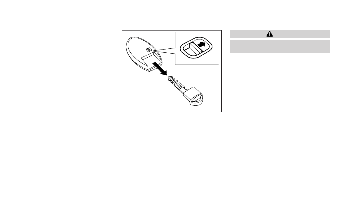
If an Intelligent Key is lost or stolen, NISSAN
recommends erasing the ID code of that
Intelligent Key from the vehicle. This may
prevent the unauthorized use of the Intelli-
gent Key to operate the vehicle. For infor-
mation regarding the erasing procedure, it
is recommended that you visit a NISSAN
dealer.
Mechanical key
The Intelligent Key contains the mechani-
cal key.
To remove the mechanical key, release the
lock knob on the back of the Intelligent Key.
To install the mechanical key, firmly insert it
into the Intelligent Key until the lock knob
returns to the lock position.
Use the mechanical key to lock or unlock
the doors and glove box (if so equipped).
For additional information, see “Doors”
(P. 3-4) and “Storage” (P. 2-69).
CAUTION
Always carry the mechanical key in-
stalled in the Intelligent Key slot.
Valet hand-off
When you have to leave a key with a valet,
give them the Intelligent Key itself and keep
the mechanical key with you to protect
your belongings.
To prevent the glove box from being
opened during valet hand-off, follow the
procedures below:
1. Remove the mechanical key from the
Intelligent Key.
2. Lock the glove box (if so equipped) with
the mechanical key.
3. Hand the Intelligent Key to the valet and
keep the mechanical key with you.
For additional information, see “Storage”
(P. 2-69).
SPA1951
Pre-driving checks and adjustments 3-3

NISSAN VEHICLE IMMOBILIZER
SYSTEM KEYS
Additional or replacement keys:
If you still have a key, the key number is not
necessary when you need extra NISSAN
Vehicle Immobilizer System keys. Your ex-
isting key can be duplicated without know-
ing the key number. As many as four
NISSAN Vehicle Immobilizer System keys
can be used with one vehicle. You should
bring all NISSAN Vehicle Immobilizer Sys-
tem keys that you have to the NISSAN
dealer for registration. This is because the
registration process will erase the memory
of all key codes previously registered into
the NISSAN Vehicle Immobilizer System. Af-
ter the registration process, these compo-
nents will only recognize keys coded into
the NISSAN Vehicle Immobilizer System
during registration. Any key that is not
given to the dealer at the time of registra-
tion will no longer be able to start your
vehicle.
CAUTION
Do not allow the immobilizer system
key, which contains an electrical tran-
sponder, to come into contact with wa-
ter or salt water. This could affect sys-
tem function.
When the doors are locked using one of the
following methods, the doors cannot be
opened using the inside or outside door
handles. The doors must be unlocked to
open the doors.
WARNING
• Always have the doors locked while
driving. Along with the use of seat
belts, this provides greater safety in
the event of an accident by helping to
prevent persons from being thrown
from the vehicle. This also helps keep
children and others from uninten-
tionally opening the doors, and will
help keep out intruders.
• Before opening any door, always look
for and avoid oncoming traffic.
DOORS
3-4 Pre-driving checks and adjustments

• To help avoid risk of injury or death
through unintended operation of the
vehicle and/or its systems, including
entrapment in windows and/or inad-
vertent door lock activation, do not
leave children, people who require
the assistance of others and/or pets
unattended in your vehicle. Addition-
ally, the temperature inside a closed
vehicle on a warm day can quickly
become high enough to cause a sig-
nificant risk of injury or death to
people and pets.
LOCKING WITH KEY
To lock the door using the mechanical key,
turn the key toward the rear of the vehicle
O
1
. This will only lock the corresponding
door and will not activate the security sys-
tem. To arm the security system, press the
button on the Intelligent Key.
To unlock the corresponding door using
the mechanical key, turn the key toward
the front of the vehicle
O
2
. This will only
unlock the corresponding door and will not
disarm the security system.
For additional information, see “Security
systems” (P. 2-50).
LPD2919
Driver's side
Pre-driving checks and adjustments 3-5

LOCKING WITH INSIDE LOCK KNOB
To lock the door without the key, move the
inside lock knob to the lock position
O
1
,
then close the door.
To unlock the door without the key, move
the inside lock knob to the unlock position
O
2
.
LOCKING WITH POWER DOOR
LOCK SWITCH
To lock all the doors without a key, push the
door lock switch (driver's or front passen-
ger's side) to the lock position
O
1
. When
locking the door this way, be certain not to
leave the key inside the vehicle.
To unlock all the doors without a key, push
the door lock switch (driver's or front pas-
senger's side) to the unlock position
O
2
.
Lockout protection
With the Intelligent Key left in the vehicle
and any door open, all doors will unlock
automatically and a chime will sound after
the door is closed.
These functions help to prevent the Intelli-
gent Key from being accidentally locked
inside the vehicle.
AUTOMATIC DOOR LOCKS
• All doors lock automatically when the ve-
hicle speed reaches 15 mph (24 km/h)
• All doors unlock automatically when the
transmission is placed in the P (Park) po-
sition or when the ignition switch is
placed in the OFF position, depending on
the option selected in the “Vehicle Set-
tings” menu.
NOTE:
The Auto Door Unlock feature can be
changed using the "Vehicle Settings"
menu on the vehicle information display.
For additional information, see “Vehicle
information display- 5 inch (13 cm) Type
A (if so equipped)” (P. 2-18) or “Vehicle
information display —7 inch (18 cm) Type
B (if so equipped)” (P. 2-33).
LPD2862
Inside lock
LPD2309
Door lock switch
3-6 Pre-driving checks and adjustments

CHILD SAFETY REAR DOOR LOCK
Child safety locks help prevent the rear
doors from being opened accidentally, es-
pecially when small children are in the
vehicle.
The child safety lock levers are located on
the edge of the rear doors.
When the lever is in the unlock position
O
2
,
the door can be opened from the outside
or the inside.
When the lever is in the LOCK position
O
1
,
the door can be opened only from the
outside.
WARNING
• Radio waves could adversely affect
electric medical equipment. Those
who use a pacemaker should contact
the electric medical equipment
manufacturer for the possible influ-
ences before use.
• The Intelligent Key transmits radio
waves when the buttons are pressed.
The FAA advises the radio waves may
affect aircraft navigation and com-
munication systems. Do not operate
the Intelligent Key while on an air-
plane. Make sure the buttons are not
operated unintentionally when the
unit is stored for a flight.
The Intelligent Key can operate all the door
locks using the remote control function or
pushing the request switch on the vehicle
without taking the key out from a pocket or
purse. The operating environment and/or
conditions may affect the Intelligent Key
operation.
Be sure to read the following before using
the Intelligent Key.
CAUTION
• Be sure to carry the Intelligent Key
with you when operating the vehicle.
• Never leave the Intelligent Key in the
vehicle when you leave the vehicle.
The Intelligent Key is always communicat-
ing with the vehicle as it receives radio
waves. The Intelligent Key transmits weak
radio waves. Environmental conditions
may interfere with the operation of the In-
telligent Key under the following operating
conditions:
• When operating near a location where
strong radio waves are transmitted, such
as a TV tower, power station and broad-
casting station.
• When in possession of wireless equip-
ment, such as a cellular telephone, trans-
ceiver or a CB radio.
• When the Intelligent Key is in contact with
or covered by metallic materials.
• When any type of radio wave remote con-
trol is used nearby.
• When the Intelligent Key is placed near an
electric appliance such as a personal
computer.
• When the vehicle is parked near a parking
meter.
LPD2863
NISSAN INTELLIGENT KEY®
Pre-driving checks and adjustments 3-7

In such cases, correct the operating condi-
tions before using the Intelligent Key func-
tion or use the mechanical key.
Although the life of the battery varies de-
pending on the operating conditions, the
battery’s life is approximately two years. If
the battery is discharged, replace it with a
new one.
When the Intelligent Key battery is low, an
indicator illuminates in the vehicle informa-
tion display. For additional information, see
“Vehicle information display - 5 inch (13 cm)
Type A (if so equipped)” (P. 2-18) or “Vehicle
information display - 7 inch (18 cm) Type B (if
so equipped)” (P. 2-33).
Since the Intelligent Key is continuously re-
ceiving radio waves, if the key is left near
equipment which transmits strong radio
waves, such as signals from a TV and per-
sonal computer, the battery life may be-
come shorter.
For additional information, see “Battery re-
placement” (P. 8-23).
As many as four Intelligent Keys can be
registered and used with one vehicle. For
information about the purchase and use of
additional Intelligent Keys, it is recom-
mended that you visit a NISSAN dealer.
CAUTION
Listed below are conditions or occur-
rences which will damage the Intelli-
gent Key:
• Do not allow the Intelligent Key,
which contains electrical compo-
nents, to come into contact with wa-
ter or salt water. This could affect the
system function.
• Do not drop the Intelligent Key.
• Do not strike the Intelligent Key
sharply against another object.
• Do not change or modify the Intelli-
gent Key.
• Wetting may damage the Intelligent
Key. If the Intelligent Key gets wet,
immediately wipe until it is com-
pletely dry.
• Do not place the Intelligent Key for an
extended period in an area where
temperatures exceed 140°F (60°C).
• Do not attach the Intelligent Key with
a key holder that contains a magnet.
• Do not place the Intelligent Key near
equipment that produces a magnetic
field, such as a TV, audio equipment
and personal computers.
If an Intelligent Key is lost or stolen, NISSAN
recommends erasing the ID code of that
Intelligent Key from the vehicle. This may
prevent the unauthorized use of the Intelli-
gent Key to operate the vehicle. For infor-
mation regarding the erasing procedure, it
is recommended that you visit a NISSAN
dealer.
3-8 Pre-driving checks and adjustments

OPERATING RANGE
The Intelligent Key functions can only be
used when the Intelligent Key is within the
specified operating range from the request
switch
O
1
.
When the Intelligent Key battery is dis-
charged or strong radio waves are present
near the operating location, the Intelligent
Key system’s operating range becomes
narrower, and the Intelligent Key may not
function properly.
The operating range is within 31.50 in (80
cm) from each request switch
O
1
.
If the Intelligent Key is too close to the door
glass, handle or rear bumper, the request
switches may not function.
When the Intelligent Key is within the oper-
ating range, it is possible for anyone, even
someone who does not carry the Intelli-
gent Key, to push the request switch to
lock/unlock the doors.
DOOR LOCKS/UNLOCKS
PRECAUTION
• Do not push the door handle request
switch with the Intelligent Key held in your
hand as illustrated. The close distance to
the door handle will cause the Intelligent
Key system to have difficulty recognizing
that the Intelligent Key is outside the
vehicle.
• After locking with the door handle re-
quest switch, verify the doors are se-
curely locked by testing them.
LPD2864
LPD2554
Pre-driving checks and adjustments 3-9

• To prevent the Intelligent Key from being
left inside the vehicle, make sure you
carry the Intelligent Key with you and then
lock the doors.
• Do not pull the door handle before push-
ing the door handle request switch. The
door will be unlocked but will not open.
Release the door handle once and pull it
again to open the door.
NISSAN INTELLIGENT KEY®
OPERATION
You can lock or unlock the doors without
taking the key out of your pocket or bag.
When you carry the Intelligent Key with you,
you can lock or unlock all doors by pushing
the door handle request switch within the
range of operation.
Locking doors
1. Move the shift lever to the P (Park) posi-
tion, place the ignition switch in the LOCK
position and make sure you carry the
Intelligent Key with you.
2. Close all doors.
3. Push any door handle request switch
O
1
while carrying the Intelligent Key with
you.
4. All doors and the trunk will lock.
5. The hazard warning lights flash twice
and the outside chime sounds twice.
LPD2865 LPD2887
3-10 Pre-driving checks and adjustments

NOTE:
• Request switches for all doors and
trunk can be deactivated when the Ext.
Door Switch or I-Key Door Lock feature
is switched to OFF using the “Vehicle
Settings” menu on the vehicle infor-
mation, see “Vehicle information dis-
play - 5 inch (13 cm) Type A (if so
equipped)” (P. 2-18) or “Vehicle infor-
mation display - 7 inch (18 cm) Type B (if
so equipped)” (P. 2-33).
• Doors lock with the door handle re-
quest switch while the ignition switch
is not in the LOCK position.
• Doors lock by pushing the driver’s side
door handle request switch while any
door is open. However, the correspond-
ing door locks with the mechanical key
even if any door is open.
• Doors do not lock with the door handle
request switch with the Intelligent Key
inside the vehicle and a beep sounds to
warn you. However, when an Intelligent
Key is inside the vehicle, doors can be
locked with another Intelligent Key.
WARNING
After locking the doors using the re-
quest switch, make sure that the doors
have been securely locked by operat-
ing the door handles. Failure to follow
these instructions may result in inad-
vertently unlocking the doors, which
may decrease the safety and security
of your vehicle.
CAUTION
• When locking the doors using the re-
quest switch, make sure to have the
Intelligent Key in your possession
before operating the request switch
to prevent the Intelligent Key from
being left in the vehicle.
• The request switch is operational
only when the Intelligent Key has
been detected by the Intelligent Key
system.
Lockout protection
To prevent the Intelligent Key from being
accidentally locked in the vehicle, lockout
protection is equipped with the Intelligent
Key.
When the driver’s side door is open, the
doors are locked and then the Intelligent
Key is put inside the vehicle and all the
doors are closed; the lock will automati-
cally unlock and the door chime sounds.
NOTE:
The doors may not lock when the Intelli-
gent Key is in the same hand that is op-
erating the request switch to lock the
door. Put the Intelligent Key in a purse,
pocket or your other hand.
LPD2165
Pre-driving checks and adjustments 3-11

CAUTION
The lockout protection may not func-
tion under the following conditions:
• When the Intelligent Key is placed on
top of the instrument panel.
• When the Intelligent Key is placed on
top of the rear parcel shelf.
• When the Intelligent Key is placed in-
side the glove box or a storage bin.
• When the Intelligent Key is placed in-
side the door pockets.
• When the Intelligent Key is placed on
or under the spare tire area.
• When the Intelligent Key is placed in-
side or near metallic materials.
Unlocking doors
1. Carry the Intelligent Key.
2. Push the door handle request switch
O
1
.
3. The hazard warning lights flash once
and the outside chime sounds once.
4. Push the door handle request switch
O
1
again within 60 seconds to unlock all
doors and trunk. The outside chime
sounds again.
If a door handle is pulled while unlocking
the doors, that door may not be unlocked.
Returning the door handle to its original
position will unlock the door. If the door
does not unlock after returning the door
handle, push the door handle request
switch to unlock the door.
All doors will be locked automatically un-
less one of the following operations is per-
formed within one minute after pushing
the request switch:
• Opening any door.
• Pushing the ignition switch.
LPD2887 LPD2165
3-12 Pre-driving checks and adjustments

Using the interior lights
The interior lights illuminate for a period of
time when a door is unlocked.
The lights can be turned off without waiting
by performing one of the following
operations:
• Placing the ignition switch in the ON
position.
• Locking the doors with the Intelligent Key.
• Switching the interior light switch to the
OFF position.
• Switching the Auto Room Lamp feature
to the OFF position in the “Vehicle Set-
tings” menu on the vehicle information
display. For additional information, see
“Vehicle information display - 5 inch (13
cm) Type A (if so equipped)” (P. 2-18) or
“Vehicle information display - 7 inch (18
cm) Type B (if so equipped)” (P. 2-33).
For additional information, see “Interior
lights” (P. 2-76).
Opening the trunk lid
To open the trunk lid, perform the following:
1. Push the trunk opener switch
O
A
for
more than 1 second while carrying the
Intelligent Key with you.
2. The trunk will unlatch. A chime will
sound four times.
3. Raise the trunk lid to open the trunk.
Lockout protection
To prevent the Intelligent Key from being
accidentally locked in the trunk, lockout
protection is equipped with the Intelligent
Key system.
When all doors are locked and the trunk lid
is closed with the Intelligent Key inside the
trunk, a chime will sound and the trunk will
open.
LPD2866
Pre-driving checks and adjustments 3-13
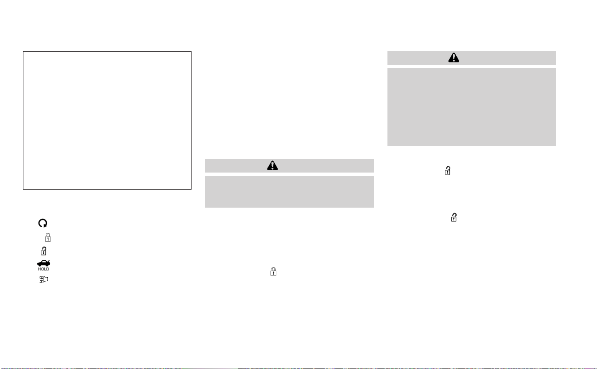
HOW TO USE THE REMOTE
KEYLESS ENTRY FUNCTION
1. (remote engine start) button
2.
(lock) button
3.
(unlock) button
4.
(trunk) button
5.
(panic) button
The remote keyless entry function can op-
erate all door locks using the remote key-
less function of the Intelligent Key. The re-
mote keyless function can operate at a
distance of 33 ft (10 m) away from the ve-
hicle. The operating distance depends
upon the conditions around the vehicle.
The remote keyless entry function will not
function under the following conditions:
• When the Intelligent Key is not within the
operational range.
• When the doors or the trunk are open or
not closed securely.
• When the Intelligent Key battery is
discharged.
CAUTION
When locking the doors using the Intel-
ligent Key, be sure not to leave the key
in the vehicle.
Locking doors
1. Place the ignition switch in the LOCK
position.
2. Close all doors.
3. Press the
button on the Intelli-
gent Key.
4. The hazard indicator lights flash twice
and the horn beeps once.
5. All doors will be locked.
WARNING
After locking the doors using the Intel-
ligent Key, be sure that the doors have
been securely locked by operating the
door handles. Failure to follow these in-
structions may result in inadvertently
unlocking the doors, which may de-
crease the safety and security of your
vehicle.
Unlocking doors
1. Press the button on the Intelligent
Key.
2. The hazard indicator lights flash once
and the driver’s door will unlock.
3. Press the
button again within 1
minute to unlock all doors and trunk.
NOTE:
The Selective Unlock feature can be
changed using the “Vehicle Settings”
menu on the vehicle information display.
For additional information, see “Vehicle
information display - 5 inch (13 cm) Type
A (if so equipped)” (P. 2-18) or “Vehicle
information display - 7 inch (18 cm) Type
B (if so equipped)” (P. 2-33).
LPD3603
3-14 Pre-driving checks and adjustments

All doors will be locked automatically un-
less one of the following operations is per-
formed within 1 minute after pressing the
button:
• Opening any doors.
• Pushing the ignition switch.
Using the interior lights
The interior lights illuminate for a period of
time when a door is unlocked.
The lights can be turned off without waiting
by performing one of the following
operations:
• Placing the ignition switch in the ON
position.
• Locking the doors with the Intelligent Key.
• Switching the interior light switch to the
OFF position.
• Switching the Auto Room Lamp feature
to the OFF position in the “Vehicle Set-
tings” menu on the vehicle information
display. For additional information, see
“Vehicle information display - 5 inch (13
cm) Type A (if so equipped)” (P. 2-18) or
“Vehicle information display - 7 inch (18
cm) Type B (if so equipped)” (P. 2-33).
For additional information, see “Interior
lights” (P. 2-76).
Opening windows
The Intelligent Key allows you to simultane-
ously open windows equipped with auto-
matic operation.
To open the windows, press the
but-
ton on the Intelligent Key longer than 3
seconds after all doors are unlocked.
The door windows cannot be closed by
using the Intelligent Key.
Releasing the trunk lid
Press the button for longer than 0.5
seconds to open the trunk lid. The trunk
release button will not operate when the
ignition switch is placed in the ON position.
Using the panic alarm
If you are near your vehicle and feel threat-
ened, you may activate the panic alarm to
call attention by pressing and holding the
button on the Intelligent Key for lon-
ger than 0.5 seconds.
The panic alarm and headlights will stay on
for a period of time.
The panic alarm stops when:
• It has run for a period of time, or
• Any button is pressed on the Intelligent
Key.
• The request switch on the driver or pas-
senger door is pushed and the Intelligent
Key is in range of the door handle.
Answer back horn feature
If desired, the answer back horn feature
can be deactivated using the Intelligent
Key. When it is deactivated and the
button is pressed, the hazard indicator
lights flash twice. When the
button is
pressed, neither the hazard indicator lights
nor the horn operates.
NOTE:
If you can change the Answer Back Horn
feature with the Intelligent Key, the ve-
hicle information display screen will
show the current mode after the ignition
switch has been cycled from the OFF to
the ON position. The vehicle information
display screen can also be used to
change the answer back horn mode.
For additional information, see “Vehicle
information display - 5 inch (13 cm) Type
A (if so equipped)” (P. 2-18 or “Vehicle in-
formation display - 7 inch (18 cm) Type B
(if so equipped)” (P. 2-33).
Pre-driving checks and adjustments 3-15

To deactivate:
Press and hold the
and but-
tons for at least 2 seconds. The hazard
indicator lights will flash three times to con-
firm that the answer back horn feature has
been deactivated.
To activate:
Press and hold the
and but-
tons for at least 2 seconds once more.
The hazard indicator lights will flash once
and the horn will sound once to confirm
that the horn beep feature has been
reactivated.
Deactivating the horn beep feature does
not silence the horn if the alarm is
triggered.
Intelligent Key button operation
light
The light blinks only when you press any
button on the Intelligent Key. The light illu-
mination only signifies that the key fob has
transmitted a signal. You may look and/or
listen to verify that the vehicle has per-
formed the intended operation.
If the light does not blink, your battery may
be too weak to communicate to the ve-
hicle. If this occurs, the battery may need to
be replaced. For additional information re-
garding the replacement of a battery, see
“Battery replacement” (P. 8-23).
WARNING SIGNALS
To help prevent the vehicle from moving
unexpectedly by erroneous operation of
the Intelligent Key or to help prevent the
vehicle from being stolen, a chime or
buzzer sounds from inside and outside the
vehicle and a warning is displayed in the
instrument panel.
When a chime or beep sounds or a warning
is displayed, be sure to check the vehicle
and the Intelligent Key.
For additional information, see “Trouble-
shooting guide” (P. 3-17) and “Vehicle infor-
mation display - 5 inch (13 cm) Type A (if so
equipped)” (P. 2-18) or “Vehicle information
display - 7 inch (18 cm) Type B (if so
equipped)” (P. 2-33).
LPD2836
3-16 Pre-driving checks and adjustments

TROUBLESHOOTING GUIDE
Verify the location of all Intelligent Keys that
are programmed for the vehicle. If another
Intelligent Key is in range or inside the ve-
hicle, the vehicle system may respond dif-
ferently than expected.
Pre-driving checks and adjustments 3-17

Symptom Possible Cause Remedy
When stopping the engine
The Shift to Park warning appears in
the display and the inside warning
chime sounds continuously.
The shift lever is not in the P (Park) po-
sition.
Move the shift lever to the P (Park) po-
sition.
When opening the driver's door to get
out of the vehicle
The Door/Trunk Open warning ap-
pears in the display and the inside
warning chime sounds continuously.
The ignition switch is in the ACC posi-
tion.
Place the ignition switch in the OFF
position.
When closing the door after getting
out of the vehicle
The No Key Detected warning appears
in the display, the outside chime
sounds three times and the inside
warning chime sounds for approxi-
mately 3 seconds.
The ignition switch is in the ACC or ON
position.
Place the ignition switch in the OFF
position.
The Shift to Park warning appears in
the display and the outside chime
sounds continuously.
The ignition switch is in the ACC posi-
tion and the shift lever is not in the P
(Park) position.
Move the shift lever to the P (Park) po-
sition and place the ignition switch in
the OFF position.
The Rear Door Alert warning message
appears on the display, the horn
sounds three times twice, or a Check
Rear Seat for All Articles warning ap-
pears on the display.
The Rear Door Alert is activated.
Check the back seat for all articles,
press the OK button to clear the Rear
Door Alert warning message.
When closing the door with the inside
lock knob turned to LOCK
The outside chime sounds for approxi-
mately 3 seconds and all the doors
unlock.
The Intelligent Key is inside the vehicle. Carr y the Intelligent Key with you.
When pushing the door handle re-
quest switch or the
button on
the Intelligent Key to lock the door
The outside chime sounds for approxi-
mately 2 seconds.
The Intelligent Key is inside the vehicle. Carr y the Intelligent Key with you.
When pushing the ignition switch to
start the engine
The Key Battery Low indicator appears
in the display.
The battery charge is low.
Replace the battery with a new one.
For additional information, see “Battery
replacement” (P. 8-23).
The Key ID Incorrect warning appears
in the display, the outside chime
sounds three times and the inside
warning chime sounds for approxi-
mately 3 seconds.
The Intelligent Key is not in the vehicle. Carry the Intelligent Key with you.
When pressing the ignition switch
The Key System Error warning appears
on the display.
It warns of a malfunction with the Intel-
ligent Key system.
It is recommended that you visit a
NISSAN dealer.
3-18 Pre-driving checks and adjustments

The button will be on the NISSAN
Intelligent Key® if the vehicle has Remote
Engine Start. This feature allows the engine
to start from outside the vehicle.
The following features may b e affected
when Remote Engine Start is used:
• Vehicles with a manual climate control
system will default to the last used heat-
ing or cooling mode.
• Vehicles with an automatic climate con-
trol system will default to either a heating
or cooling mode depending on outside
and cabin temperatures. For additional
information, see “Remote Engine Start
with Intelligent Climate Control” (P. 4-41).
Laws in some local communities may re-
strict or prohibit the use of Remote Engine
Start, or the amount of time a parked ve-
hicle engine may idle. For example, some
laws require a person using Remote Engine
Start to have the vehicle in view or may
restrict idling time except in freezing tem-
peratures. Check local regulations for any
requirements.
Other conditions may affect the function of
the Remote Engine Start feature. For addi-
tional information, see “Conditions the Re-
mote Engine Start will not work” (P. 3-21).
Other conditions can affect the perfor-
mance of the Intelligent Key transmitter.
For additional information, see “NISSAN In-
telligent Key®” (P. 3-2).
REMOTE ENGINE START
OPERATING RANGE
WARNING
• To help avoid risk of injury or death
through unintended operation of the
vehicle and/or its systems, including
entrapment in windows or inadver-
tent door lock activation, do not
leave children, people who require
the assistance of others or pets unat-
tended in your vehicle. Additionally,
the temperature inside a closed ve-
hicle on a warm day can quickly be-
come high enough to cause a signifi-
cant risk of injury or death to people
and pets.
• Do not use Remote Engine Start in
closed spaces such as a garage. Do
not breathe exhaust gases; they con-
tain colorless and odorless carbon
monoxide. Carbon monoxide is dan-
gerous. It can cause unconscious-
ness or death.
LPD2995
REMOTE ENGINE START
Pre-driving checks and adjustments 3-19

CAUTION
When the Intelligent Key battery is dis-
charged or other strong radio wave
sources are present near the operating
location, the Intelligent Key operating
range becomes narrower, and the Intel-
ligent Key may not function properly.
The Remote Engine Start function can only
be used when the Intelligent Key is within
the specified operating range from the
vehicle.
The Remote Engine Start operating range
is approximately 197 ft (60 m) from the
vehicle.
REMOTE STARTING THE VEHICLE
To use the Remote Engine Start feature to
start the engine perform the following:
1. Aim the Intelligent Key at the vehicle.
2. Press the
button to lock all doors.
3. Within 5 seconds press and hold the
button until the turn signal lights
flash and the tail lamps turn on. If the
vehicle is not within view press and hold
the
button for at least 2 seconds.
The following events will occur when the
engine starts:
• The parking lights will turn on and remain
on as long as the engine is running.
• The doors will be locked and the climate
control system may come on.
• The engine will continue to run for 10 min-
utes. Repeat the steps to extend the time
for an additional 10 minutes. For addi-
tional information, see “Extending engine
run time” (P. 3-20).
Depress and hold the brake then push the
push-button ignition switch to the ON po-
sition before driving. For additional infor-
mation, see “Driving the vehicle” (P. 5-18).
EXTENDING ENGINE RUN TIME
The Remote Engine Start feature can be
extended one time by performing the
steps listed in “Remote starting the vehicle”
in this section. Run time will be calculated
as follows:
• The first 10 minute run time will start
when the Remote Engine Start function is
performed.
• The second 10 minutes will start immedi-
ately when the Remote Engine Start
function is performed again. For example,
if the engine has been running for 5 min-
utes, and 10 minutes are added, the en-
gine will run for a total of 15 minutes.
• Extending engine run time will count to-
wards the two Remote Engine Start limit.
A maximum of two Remote Engine Starts,
or a single Remote Engine Start with an
extension, are allowed between ignition
cycles. The ignition switch must be cycled
to the ON position and then back to the
OFF position before the Remote Engine
Start procedure can be used again.
CANCELING A REMOTE ENGINE
START
To cancel a Remote Engine Start, perform
one of the following:
• Aim the Intelligent Key at the vehicle and
press
until the parking lights turn off.
• Turn on the hazard warning flashers.
• Cycle the ignition switch ON and then
OFF.
• The extended engine run time has
expired.
• The first 10 minute timer has expired.
• The engine hood has been opened.
3-20 Pre-driving checks and adjustments

• The shift lever is moved out of park.
• The alarm sounds due to illegal entry into
the vehicle.
• The ignition switch is pushed without an
Intelligent Key in the vehicle.
• The ignition switch is pushed with an In-
telligent Key in the vehicle but the brake
pedal is not depressed.
CONDITIONS THE REMOTE ENGINE
START WILL NOT WORK
The Remote Engine Start will not operate if
any of the following conditions are present:
• The ignition switch is placed in the ON
position.
• The hood is not securely closed.
• The hazard indicator lights are on.
• The engine is still running. The engine
must be completely stopped. Wait at
least 6 seconds if the engine goes from
running to off. This is not applicable when
extending engine run time.
• The
button is not pressed and held
for at least 2 seconds.
• The
button is not pressed and held
within 5 seconds of pressing the lock
button.
• The brake is pressed.
• The doors are not closed and locked.
• The trunk is open.
• The Key System Error remains solid in the
vehicle information display.
• The alarm sounds due to illegal entry into
the vehicle.
• Two Remote Engine Starts, or a single
Remote Engine Start with an extension,
have already been used.
• The vehicle is not in P (Park).
• There is a detected registered key already
inside of the vehicle.
• The Remote Engine Start feature has
been switched to the OFF using the “Ve-
hicle Settings” menu on the vehicle infor-
mation display. For additional informa-
tion, see “Vehicle information display - 5
inch (13 cm) Type A (if so equipped)”
(P. 2-18) or “Vehicle information display - 7
inch (18 cm) Type B (if so equipped)”
(P. 2-33).
The Remote Engine Start may display a
warning or indicator in the vehicle informa-
tion display. For additional information, see
“Vehicle information display - 5 inch (13 cm)
Type A (if so equipped)” (P. 2-18) or “Vehicle
information display - 7 inch (18 cm) Type B (if
so equipped)” (P. 2-33).
Pre-driving checks and adjustments 3-21

1. Pull the hood lock release handle
O
1
lo-
cated below the driver's side instrument
panel; the hood springs up slightly.
2. To open the hood, push the lever
O
2
un-
derneath the front of the hood upwards
with your fingertips as illustrated and
raise the hood.
3. Remove the support rod from the clamp
O
3
.
4. Insert the support rod
O
4
into the slot on
the passenger side of the hood.
5. When closing the hood, return the sup-
port rod to its original position, lower the
hood to approximately 12 in (30 cm)
above the latch and release it. This al-
lows proper engagement of the hood
latch.
WARNING
• Make sure the hood is completely
closed and latched before driving.
The vehicle should only ever be oper-
ated with the hood securely closed.
• If you see steam or smoke coming
from the engine compartment, to
avoid injury do not open the hood.
OPENER OPERATION
WARNING
• Do not drive with the trunk lid open.
This could allow dangerous exhaust
gases to be drawn into the vehicle.
For additional information, see “Ex-
haust gas (carbon monoxide)”
(P. 5-4).
LPD3011 LPD2932
Instrument panel
HOOD TRUNK LID
3-22 Pre-driving checks and adjustments
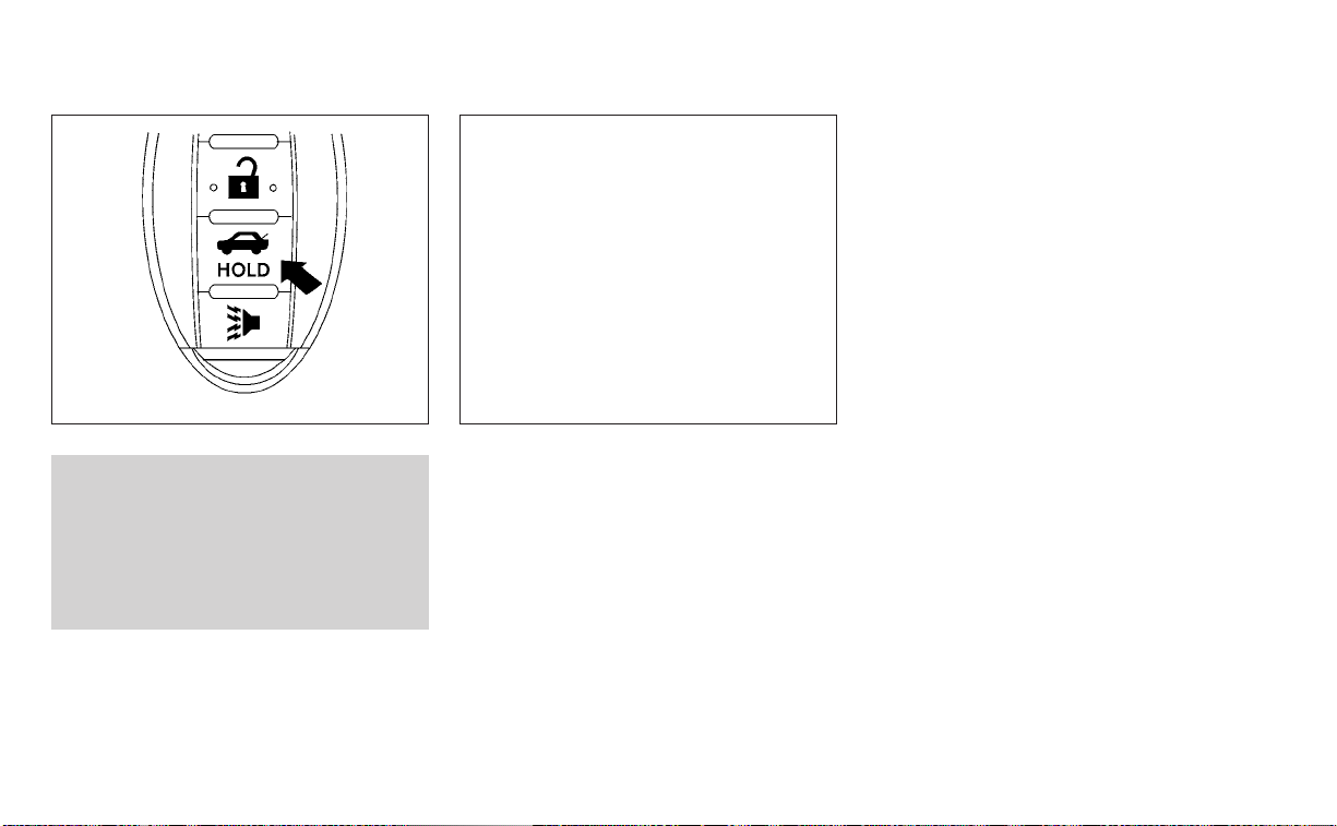
• Closely supervise children when they
are around cars to prevent them
from playing and becoming locked in
the trunk where they could be seri-
ously injured. Keep the car locked,
with the rear seatback and trunk lid
securely latched when not in use, and
prevent children's access to car keys.
To open the trunk lid perform one of the
following after unlocking all doors:
• Press the button on the instrument
panel.
• Press the button on the Intelligent Key.
• Push the trunk opener switch
O
A
.
To close the trunk lid, lower and push the
trunk lid down securely.
NOTE:
Request switches for all doors and trunk
can be deactivated when the Ext Door
Switch or I-Key Door Lock feature is
switched to OFF in the “Vehicle Settings”
of the vehicle information display. For
additional information, see “Vehicle in-
formation display - 5 inch (13 cm) Type A
(if so equipped)” (P. 2-18) or “Vehicle in-
formation display - 7 inch (18 cm) Type B
(if so equipped)” (P. 2-33).
WPD0364
Intelligent Key
LPD2866
Trunk opener switch
Pre-driving checks and adjustments 3-23

INTERIOR TRUNK LID RELEASE
WARNING
Closely supervise children when they
are around cars to prevent them from
playing and becoming locked in the
trunk where they could be seriously in-
jured. Keep the car locked, with the rear
seatback and trunk lid securely latched
when not in use, and prevent children's
access to car keys.
The interior trunk lid release mechanism
provides a means of escape for children
and adults in the event they become
locked inside the trunk.
To open the trunk from the inside, pull the
illuminated release handle until the lock re-
leases and push up on the trunk lid. The
release handle is made of a material that
glows in the dark after a brief exposure to
ambient light.
The handle is located inside the trunk com-
partment on the interior of the trunk lid.
INTERIOR TRUNK ACCESS
The trunk can be accessed from the pas-
senger side of the rear seat.
1. Move the front passenger seat to the
most forward position.
2. Open the access cover on the rear par-
cel shelf.
3. Slide the handle in the direction of the
arrow.
4. Fold down the passenger’s side
seatback.
For additional information, see “Folding
rear seat” (P. 1-5).
WARNING
• Never allow anyone to ride in the
cargo area or on the rear seat when it
is in the fold-down position. Use of
these areas by passengers without
proper restraints could result in seri-
ous injury or death in an accident or
sudden stop.
• Properly secure all cargo with ropes
or straps to help prevent it from slid-
ing or shifting. Do not place cargo
higher than the seatbacks. In a sud-
den stop or collision, unsecured
cargo could cause personal injury.
• When returning the seatbacks to the
upright position, be certain they are
completely secured in the latched
position. If they are not completely
secured, passengers may be injured
in an accident or sudden stop.
• Closely supervise children when they
are around cars to prevent them
from playing and becoming locked in
the trunk where they could be seri-
ously injured. Keep the car locked,
with the rear seatback and trunk lid
securely latched when not in use, and
prevent children's access to car keys.
LPD2081
3-24 Pre-driving checks and adjustments
OPENER OPERATION
The fuel-filler door release is located below
the instrument panel. To open the fuel-filler
door, pull the release. To lock, close the fuel-
filler door securely.
FUEL-FILLER CAP
WARNING
• Gasoline is extremely flammable and
highly explosive under certain condi-
tions. You could be burned or seri-
ously injured if it is misused or mis-
handled. Always stop the engine and
do not smoke or allow open flames or
sparks near the vehicle when
refueling.
• Do not attempt to top off the fuel
tank after the fuel pump nozzle
shuts off automatically. Continued
refueling may cause fuel overflow,
resulting in fuel spray and possibly a
fire.
• Use only an original equipment type
fuel-filler cap as a replacement. It has
a built-in safety valve needed for
proper operation of the fuel system
and emission control system. An in-
correct cap can result in a serious
malfunction and possible injury. It
could also cause the
Malfunc-
tion Indicator Light (MIL) to come on.
• Never pour fuel into the throttle body
to attempt to start your vehicle.
• Do not fill a portable fuel container in
the vehicle or trailer. Static electricity
can cause an explosion of flammable
liquid, vapor or gas in any vehicle or
trailer. To reduce the risk of serious
injury or death when filling portable
fuel containers:
– Always place the container on the
ground when filling.
– Do not use electronic devices
when filling.
– Keep the pump nozzle in contact
with the container while you are
filling it.
– Use only approved portable fuel
containers for flammable liquid.
CAUTION
• Do not use a fuel that contains more
than 15% ethanol in your vehicle. For
additional information, see “Fuel rec-
ommendation” (P. 10-4).
LPD2869
FUEL-FILLER DOOR
Pre-driving checks and adjustments 3-25

• The Loose Fuel Cap warning mes-
sage will be displayed/warning will
appear if the fuel-filler cap is not
properly tightened. It may take a few
driving trips for the message to be
displayed. Failure to tighten the fuel-
filler cap properly after the Loose
Fuel Cap warning message is
displayed/warning appears may
cause the
Malfunction Indicator
Light (MIL) to illuminate.
• Failure to tighten the fuel-filler cap
properly may cause the
Mal-
function Indicator Light (MIL) to illu-
minate. If the
light illuminates
because the fuel-filler cap is loose or
missing, tighten or install the cap and
continue to drive the vehicle. The
light should turn off after a few
driving trips. If the
light does not
turn off after a few driving trips, have
the vehicle inspected. It is recom-
mended that you visit a NISSAN
dealer for this service.
• For additional information, see “Mal-
function Indicator Light (MIL)”
(P. 2-15).
• If fuel is spilled on the vehicle body,
flush it away with water to avoid
paint damage.
To remove the fuel-filler cap:
1. Turn the fuel-filler cap counterclockwise
to remove.
2. Put the fuel-filler cap on the cap holder
O
1
while refueling.
To install the fuel-filler cap:
1. Insert the fuel-filler cap straight into the
fuel-filler tube.
2. Turn the fuel-filler cap clockwise until it
clicks. The fuel-filler cap is a ratcheting
type.
Loose Fuel Cap warning
The Loose Fuel Cap warning message will
be displayed in the vehicle information dis-
play when the fuel-filler cap is not tight-
ened correctly after the vehicle has been
refueled. It may take a few driving trips for
the message to be displayed. To turn off
the warning, perform the following:
1. Remove and install the fuel-filler cap as
soon as possible. For additional informa-
tion, see “Fuel-filler cap” (P. 3-25)
2. Tighten the fuel-filler cap until it clicks.
LPD2870 LPD3029
3-26 Pre-driving checks and adjustments

3. Press the OK button on the steering
wheel for about 1 second to turn off the
Loose Fuel Cap warning after tightening
the fuel-filler cap.
WARNING
• Do not adjust the steering wheel
while driving. You could lose control
of your vehicle and cause an
accident.
• Do not adjust the steering wheel any
closer to you than is necessary for
proper steering operation and com-
fort. The driver's air bag inflates with
great force. If you are unrestrained,
leaning forward, sitting sideways or
out of position in any way, you are at
greater risk of injury or death in a
crash. You may also receive serious
or fatal injuries from the air bag if you
are up against it when it inflates. Al-
ways sit back against the seatback
and as far away as practical from the
steering wheel. Always use the seat
belts.
TILT OPERATION
Pull the lock lever down and hold on until
the end of the stroke
O
1
and adjust the
steering wheel up or down
O
2
to the de-
sired position.
Push the lock lever up
O
1
firmly and hold on
until end of stroke to lock the steering
wheel in place.
TELESCOPIC OPERATION
Pull the lock lever down
O
1
and adjust the
steering wheel forward or backward
O
3
to
the desired position.
LPD2871
STEERING WHEEL
Pre-driving checks and adjustments 3-27
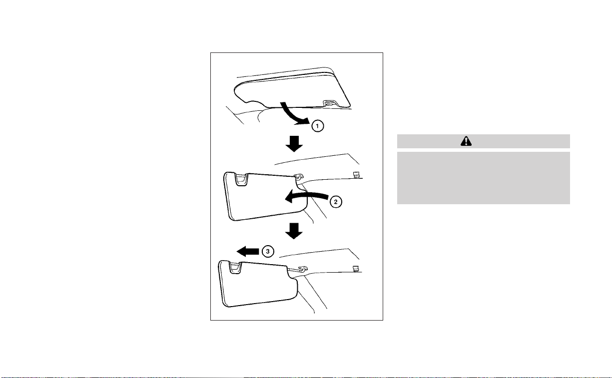
Push the lock lever up
O
1
firmly and hold on
until end of stroke to lock the steering
wheel in place.
1. To block glare from the front, swing
down the main sun visor
O
1
.
2. To block glare from the side, remove the
main sun visor
O
2
from the center
mount and swing the visor to the side.
3. To extend the sun visor, slide in or out as
needed
O
3
.
CAUTION
• Do not store the sun visor before re-
turning the extension to its original
position.
• Do not pull the extension sun visor
for cedly downward.
WPD0344
SUN VISORS
3-28 Pre-driving checks and adjustments
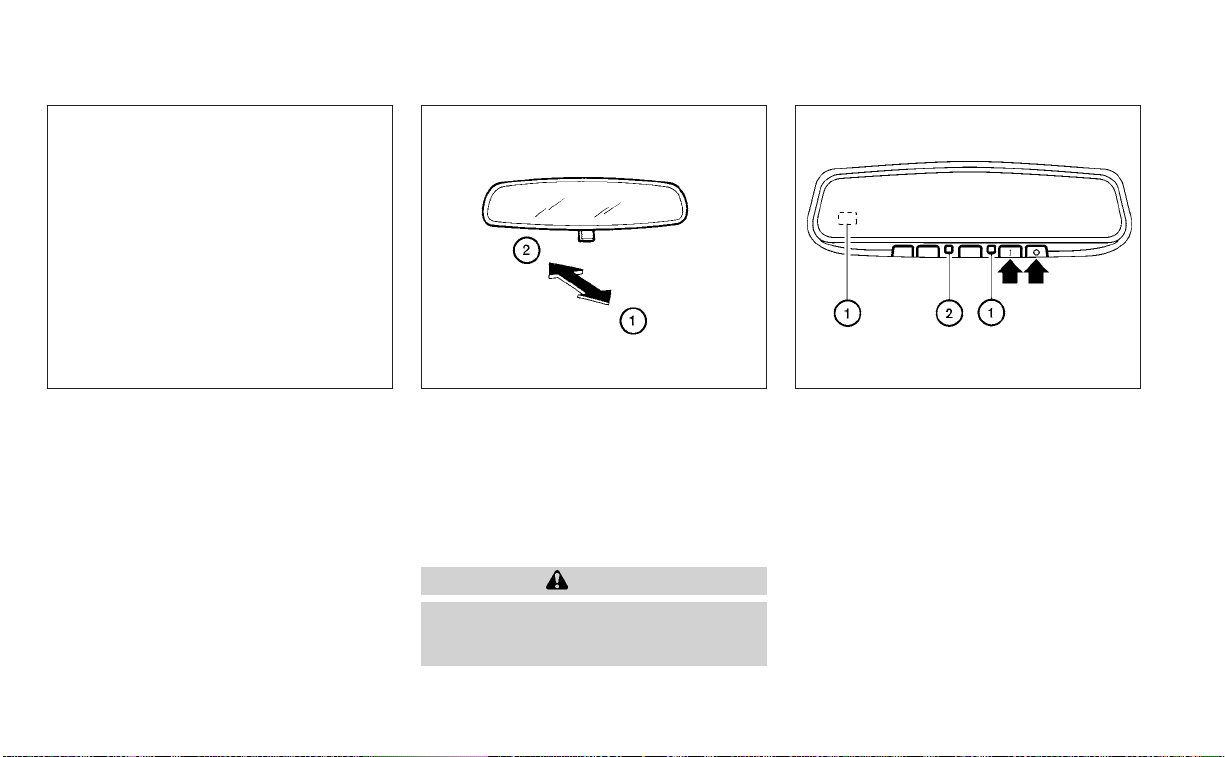
VANITY MIRRORS
To access the vanity mirror, pull the sun
visor down and flip open the mirror cover.
Some vanity mirrors are illuminated and
turn on when the mirror cover is open.
MANUAL ANTI-GLARE REARVIEW
MIRROR (if so equipped)
Use the night position
O
1
to reduce glare
from the headlights of vehicles behind you
at night.
Use the day position
O
2
when driving in
daylight hours.
WARNING
Use the night position only when nec-
essary, because it reduces rear view
clarity.
AUTOMATIC ANTI-GLARE
REARVIEW MIRROR (if so equipped)
The inside mirror is designed so that it au-
tomatically dims during night time condi-
tions and according to the intensity of the
headlights of the vehicle following you. The
automatic anti-glare feature is activated
when the ignition switch is in the ON
position.
LPD2589 WPD0126 LPD0469
MIRRORS
Pre-driving checks and adjustments 3-29

NOTE:
Do not hang any objects over the sen-
sors
O
1
or apply glass cleaner to the sen-
sors. Doing so will reduce the sensitivity
of the sensors, resulting in improper
operation.
The indicator light
O
2
will illuminate when
the automatic anti-glare feature is
operating.
• To turn off the anti-glare feature, press
the O button. The indicator light will
turn off.
• To turn on the anti-glare feature, press
the | button. The indicator light will turn
on.
For information on HomeLink® Universal
Transceiver operation, see the “HomeLink®
Universal Transceiver” (P. 2-78).
OUTSIDE MIRRORS
The outside mirror remote control only op-
erates when the ignition switch is placed in
the ON position.
Move the small switch
O
1
to select the right
or left mirror. Adjust each mirror to the de-
sired position using the large switch
O
2
.
Move the small switch
O
1
to the center
(neutral) position to prevent accidentally
moving the mirror.
WARNING
• Do not adjust the mirrors while driv-
ing. You could lose control of your ve-
hicle and cause an accident.
• Objects viewed in the outside mirror
on the passenger side are closer than
they appear. Be careful when moving
to the right. Using only this mirror
could cause an accident. Use the in-
side mirror or glance over your
shoulder to properly judge distances
to other objects.
LPD2452
3-30 Pre-driving checks and adjustments

Manual folding outside mirrors
Pull the outside mirror toward the door to
fold it.
Heated mirrors (if so equipped)
Some outside mirrors can be heated to
defog, defrost or de-ice for improved visibil-
ity. For additional information, see “Rear
window and outside mirror (if so equipped)
defroster switch” (P. 2-54).
The memory seat system has three
features:
• Memory storage function (Key-link)
• Memory storage function (Switch)
• Entry/exit function
Key-link, when enabled, automatically re-
tains the driver’s last seat and outside mir-
ror (if so equipped) position for that specific
key when the ignition is turned from ON to
OFF.
Each memory switch button (1 or 2) on the
driver’s door can also store one additional
position which is independent of the key-
linked position.
MEMORY STORAGE FUNCTION
Use the following process to setup key-link:
1. Unlock the vehicle with the desired Intel-
ligent Key while the ignition is OFF.
2. Place the ignition in the ON position.
3. Within the “Settings” menu of the vehicle
information display, select “Key-Linked
Settings” and press the OK button on the
steering switch.
4. While in the menu, press the OK button
on the steering switch to turn the sys-
tem ON/OFF.
LPD2084 LPD2432
MEMORY SEAT (if so equipped)
Pre-driving checks and adjustments 3-31

Once step 4 is completed, every time the
ignition is switched from ON to OFF, the
memory positions of the driver’s seat and
outside mirror (if so equipped) are linked to
the Intelligent Key.
Follow the same procedure if you want
to link the 2nd, 3rd or 4th Intelligent Key.
NOTE:
If new memory positions are set prior to
turning the ignition from ON to OFF, the
previously linked memory positions for
the respective key will be overwritten by
new positions.
Recalling Intelligent Key memory
positions
If the “Key-Linked Settings” are enabled in
the vehicle information display for that par-
ticular key, every time you enter the vehicle
the driver’s seat and outside mirrors (if so
equipped) will automatically move to the
driver’s last position of the respective Intel-
ligent Key.
NOTE:
The key-linked memory positions can be
different from the positions stored in the
memory switch (1 or 2).
MEMORY STORAGE FUNCTION
(switch)
Use the following process to manually
store the two memory positions in the
switch:
1. The vehicle should be stopped while set-
ting the memory.
2. Adjust the driver's seat and outside mir-
ror (if so equipped) to the desired posi-
tions by manually operating each ad-
justing switch. For additional
information, see “Front power seat ad-
justment” (P. 1-4) and “Outside mirrors”
(P. 3-30).
3. Push the SET switch and, within 5 sec-
onds, push the memory switch (1 or 2).
The indicator light for the pushed memory
switch will come on and stay on for ap-
proximately 5 seconds. The chime will
sound when the memory is stored.
NOTE:
If a new memory position is stored in the
same memory switch, the previous
memory position will be overwritten by
the new stored position.
Recalling switch memory
positions
To recall the manually stored positions,
press the memory switch (1 or 2). The driv-
er’s seat and outside mirror (if so equipped)
will move to the positions stored to those
buttons.
LPD2872
3-32 Pre-driving checks and adjustments

ENTRY/EXIT FUNCTION
This system is designed so that the driver's
seat will automatically move when the shift
lever is in the P (Park) position. This allows
the driver to easily get in and out of the
driver’s seat.
The driver’s seat will slide backward:
• When the driver's door is opened and the
ignition switch is in the OFF position.
• When the ignition switch is turned from
ACC to OFF with the driver’s door open.
The driver’s seat will return to the previous
position:
• When the ignition switch is turned to ACC
or ON while the shift lever is in the P (Park)
position.
The entry/exit function can be adjusted or
canceled through the “Vehicle Settings” in
the vehicle information display by perform-
ing the following:
• Switch the Exit Seat Slide from ON to OFF.
SYSTEM OPERATION
The memory seat system will not work or
will stop operating under the following
conditions:
• When the vehicle speed is above 4 mph (7
km/h).
• When any of the memory switches are
pushed while the memory seat is
operating.
• When the switch for the driver’s seat and
steering column is pushed while the
memory seat is operating.
• When the seat has already been moved
to the memorized position.
• When no seat position is stored in the
memory switch.
• When the shift lever is moved from P
(Park) to any other position.
The memory seat system can be adjusted
and canceled. It is recommended you visit
a NISSAN dealer for this service.
Pre-driving checks and adjustments 3-33

4 Monitor, climate, audio, phone and
voice recognition systems
NissanConnect® Owner’s Manual ...............4-2
Control panel buttons ...........................4-3
How to use the touch-screen ................4-4
How to use the
MENU button ...........4-5
(brightness control) button .............4-7
How to use the VOL (volume) knob /
PUSH
(power)button....................4-7
Selecting menu from launch bar .............4-7
RearView Monitor (if so equipped) ...............4-8
RearView Monitor system operation ..........4-9
How to read the displayed lines ..............4-9
Difference between predicted and
actual distances ............................4-10
How to park with predicted course
lines ..........................................4-11
Adjusting the screen ........................4-13
How to turn on and off predicted
course lines .................................4-13
RearView Monitor system limitations ........4-13
System maintenance .......................4-14
Intelligent Around View Monitor
(if so equipped) .................................4-15
Intelligent Around View Monitor system
operation ...................................4-16
Difference between predicted and
actual distances ............................4-19
How to park with predicted course
lines .........................................4-21
How to switch the display ...................4-22
Adjusting the screen ........................4-23
Intelligent Around View Monitor system
limitations ..................................4-23
System maintenance .......................4-25
Moving Object Detection (MOD)
(if so equipped) .................................4-26
MOD system operation ......................4-27
Turning MOD on and off (if so equipped) .....4-29
MOD system limitations .....................4-29
System maintenance .......................4-30
Vents ..........................................4-30
Heater and air conditioner (manual)
(if so equipped) .................................4-32
Controls .....................................4-33
Heater operation ............................4-33
Air conditioner operation ....................4-34
Air flow charts ...............................4-35
Heater and air conditioner (automatic)
(if so equipped) .................................4-39
Automatic operation ........................4-40
Manual operation ...........................4-41
Operating tips ...............................4-42

Servicing air conditioner ........................4-43
Audio system ..................................4-44
Radio .......................................4-44
FM radio reception ..........................4-44
AM radio reception ..........................4-44
Audio operation precautions ................4-45
FM/AM radio ................................4-48
USB (Universal Serial Bus) Connection
Port.........................................4-53
iPod®* player operation .....................4-56
Bluetooth® streaming audio.................4-59
Steering wheel switch for audio control .....4-62
USB/iPod® charging port (if so equipped) .......4-63
Antenna........................................4-63
Siri® Eyes Free (if so equipped) ..................4-63
Requirements ...............................4-64
Operating Siri® Eyes Free ....................4-64
Troubleshooting guide ......................4-65
Car phone or CB radio..........................4-66
Bluetooth® Hands-Free Phone System .........4-66
Regulatory information ......................4-68
Using the system ...........................4-68
Indicators ...................................4-70
Control buttons .............................4-70
Bluetooth® connecting procedure ...........4-71
Voice commands ...........................4-72
Phone display screen .......................4-74
Making a call ................................4-75
Receiving/Ending a call ......................4-75
During a call .................................4-75
Text messaging (if so equipped) .............4-76
Bluetooth® connections screen .............4-80
Phone and tex t message settings ...........4-81
Volume & beeps .............................4-83
iPod®/iPhone® .................................4-83

Refer to the NissanConnect® Owner’s
Manual that includes the following infor-
mation.
• NissanConnect® Services (if so equipped)
• Navigation system (if so equipped)
• Audio system
• Apple CarPlay® (if so equipped)
• Android Auto
TM
(if so equipped)
• Bluetooth® Hands-Free Phone system
• Viewing information
• Other settings
• Voice recognition
• General system information
NISSANCONNECT® OWNER’S
MANUAL
4-2 Monitor, climate, audio, phone and voice recognition systems

1. Display screen
2. TUNE·SCROLL knob / PUSH SOUND
button
3.
BACK button
4. DISP button
5.
button*
6.
MENU button
7.
(brightness control) button
8. VOL (volume) knob / PUSH
(power)
button
* For additional information regarding the
Bluetooth® Hands-Free Phone System
control button, see “Bluetooth® Hands-
Free Phone System” (P. 4-66).
When you use this system, make sure the
engine is running.
If you use the system with the engine not
running for a long time, it will discharge
the battery, and the engine will not start.
Reference symbols:
“Example” — Words marked in quotes refer
to a key shown only on the display. These
keys can be selected by touching the
screen.
LHA4960
CONTROL PANEL BUTTONS
Monitor, climate, audio, phone and voice recognition systems 4-3
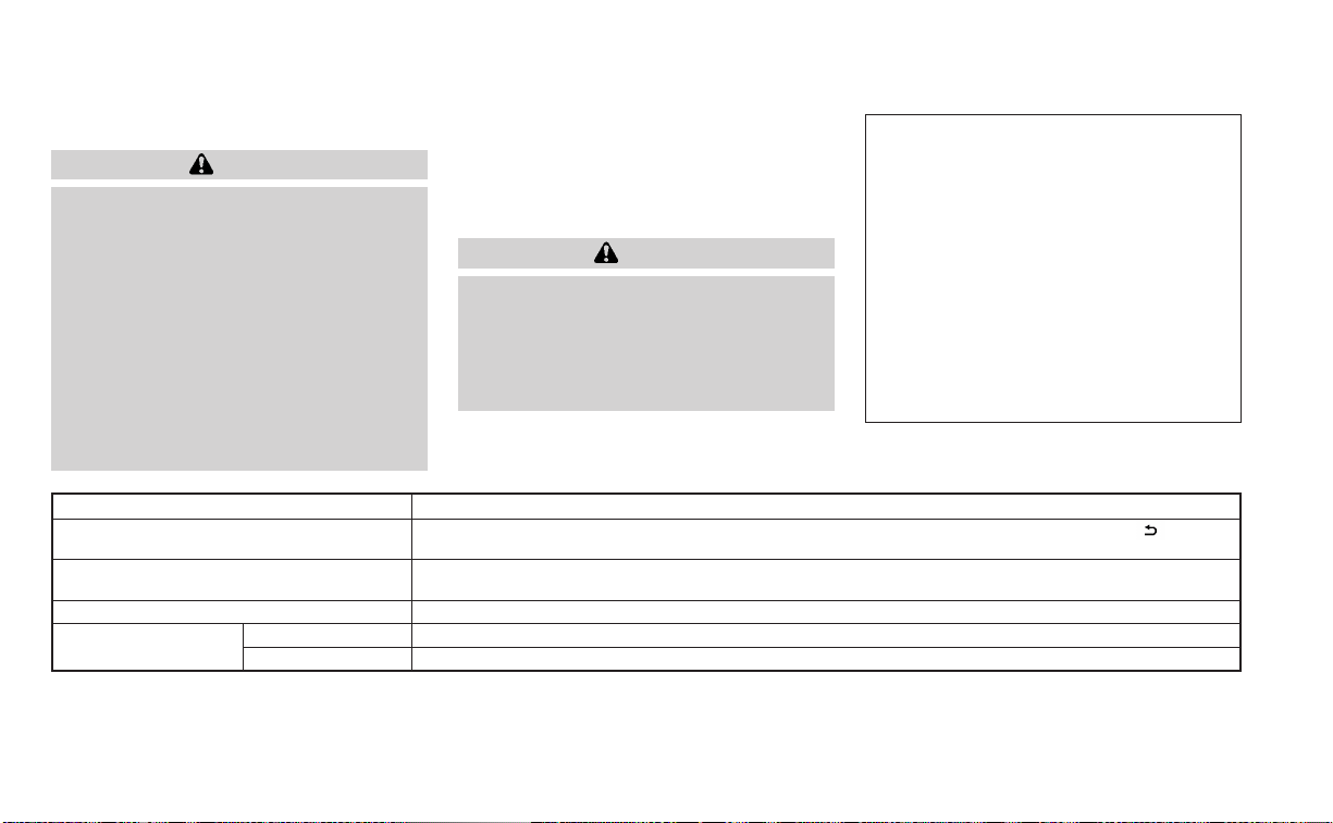
HOW TO USE THE TOUCH-SCREEN
CAUTION
• The glass display screen may break if
it is hit with a hard or sharp object. If
the glass screen breaks, do not touch
it. Doing so could result in an injury.
• To clean the display, never use a
rough cloth, alcohol, benzine, thinner
or any kind of solvent or paper towel
with a chemical cleaning agent. They
will scratch or deteriorate the panel.
• Do not splash any liquid such as wa-
ter or car fragrance on the display.
Contact with liquid will cause the sys-
tem to malfunction.
To help ensure safe driving, some functions
cannot be operated while driving.
The on-screen functions that are not avail-
able while driving will be “grayed out” or
muted.
WARNING
• ALWAYS give your full attention to
driving.
• Avoid using vehicle features that
could distract you. If distracted, you
could lose control of your vehicle and
cause an accident.
Touch-screen operation
Menu Item Result
Selecting the item Touch an item to select. To select the “Phone” key, touch the “Phone” key on the screen. Touch the “
”keyto
return to the previous screen.
Adjusting the item Touch the “+” key or the “−” key to adjust the settings of an item. Touch the up arrow to scroll up the page one
item at a time. Touch the down arrow to scroll down the page one item at a time.
Inputting characters Touch the number key. There are some options available when inputting characters.
123 Touch to manually enter numbers.
OK Completes the character input.
LHA5318
4-4 Monitor, climate, audio, phone and voice recognition systems

Touch-screen maintenance
If you clean the display screen, use a dry,
soft cloth. If additional cleaning is neces-
sary, use a small amount of neutral deter-
gent with a soft cloth. Never spray the
screen with water or detergent. Dampen
the cloth first and then wipe the screen.
HOW TO USE THE MENU
BUTTON
To select and/or adjust several functions,
features and modes that are available for
your vehicle:
1. Press the
MENU button.
2. Touch the “Settings” key.
3. Touch the desired item.
LHA5319 LHA5318
Monitor, climate, audio, phone and voice recognition systems 4-5

Menu item Result
Settings Touch to change the following settings.
Connections Touch this key to select either Bluetooth® phone, Bluetooth® audio or USB audio options. For additional in-
formation, see “USB connections screen” (P. 4-54) and “Bluetooth® connections screen” (P. 4-80) in this sec-
tion.
Phone For additional information, see “Bluetooth® Hands-Free Phone System” (P. 4-66) in this section.
Sound For additional information, see “Audio system” (P. 4-44) in this section.
Volume & Beeps For additional information, see “Volume & beeps” (P. 4-83) in this section.
Clock Touch this key to adjust clock settings.
On-screen Clock Touch to toggle ON or OFF the clock display on the upper right corner of the display screen.
Clock Format Touch to set the clock to 12 hour or 24 hour formats.
Daylight Savings Time Touch to adjusts the daylight saving time to on or off.
Set Clock Manually Touch to adjust the clock manually; then touch to change between AM and PM, the hour and the minutes.
System Voice For additional information, see “Settings” (P. 4-74) in this section.
Camera Touch this key to change the camera settings.
Others Touch this key to select and/or adjust various functions of this system. A screen with additional options will
appear.
Display Touch this key to adjust the appearance of the display. For additional information, see “Adjusting the
screen” (P. 4-13, 4-23) in this section.
Language Touch this key to change the language on the display.
OSS Licenses Touch this key to display software licensing information.
Return All Settings to Default Touch this key to return all settings to default and to clear the memory.
4-6 Monitor, climate, audio, phone and voice recognition systems

(brightness control) BUTTON
To change the display brightness, press the
button. Pressing the button again will
change the display to the day or the night
display.
Press and hold the
button for more
than 2 seconds to turn the display off. Press
and hold the button again to turn the dis-
play on.
HOW TO USE THE VOL (volume)
KNOB / PUSH
(power)
BUTTON
Press the PUSH (power) button to turn
audio function on and off. Turn the VOL
(volume) knob to adjust audio volume.
SELECTING MENU FROM LAUNCH
BAR
Various system functions can be accessed
by touching the items on the Launch Bar
O
1
which is displayed on most of the main
menu screens (the Launch Bar does not
appear on some screens such as settings
screens, camera screens, etc.)
Touch the keys on the Launch Bar to dis-
play the corresponding menu screens.
The following menu items are available on
the Launch Bar:
•AM
•FM
• USB/iPod
• Bluetooth
•AUX
• Settings
LHA4707
Monitor, climate, audio, phone and voice recognition systems 4-7

1. CAMERA or DISP button
WARNING
• Failure to follow the warnings and in-
structions for proper use of the Rear-
View Monitor system could result in
serious injury or death.
• RearView Monitor is a convenience
feature and is not a substitute for
proper backing. Always turn and look
out the windows and check mirrors
to be sure that it is safe to move be-
fore operating the vehicle. Always
back up slowly.
• The system is designed as an aid to
the driver in showing large station-
ary objects directly behind the ve-
hicle, to help avoid damaging the
vehicle.
LHA4800
REARVIEW MONITOR (if so
equipped)
4-8 Monitor, climate, audio, phone and voice recognition systems

• The distance guide lines and the ve-
hicle width lines should be used as a
reference only when the vehicle is on
a level paved surface. The distance
viewed on the monitor is for refer-
ence only and may be different than
the actual distance between the ve-
hicle and displayed objects.
CAUTION
Do not scratch the camera lens when
cleaning dirt or snow from the front of
the camera.
The RearView Monitor system automati-
cally shows a rear view of the vehicle when
the shift lever is shifted into the R (Reverse)
position. The radio can still be heard while
the RearView Monitor is active.
To display the rear view, the RearView Moni-
tor system uses a camera located just
above the vehicle’s license plate
O
1
.
REARVIEW MONITOR SYSTEM
OPERATION
With the ignition switch in the ON position,
move the shift lever to the R (Reverse) po-
sition to operate the RearView Monitor.
HOW TO READ THE DISPLAYED
LINES
Guiding lines which indicate the vehicle
width and distances to objects with refer-
ence to the vehicle body line
O
A
are dis-
played on the monitor.
Distance guide lines
Indicate distances from the vehicle body.
• Red line
O
1
: approx. 1.5 ft (0.5 m)
• Yellow line
O
2
: approx. 3 ft (1 m)
• Green line
O
3
: approx. 7 ft (2 m)
LHA4801 LHA4805
Monitor, climate, audio, phone and voice recognition systems 4-9

Vehicle width guide lines
O
4
Indicate the vehicle width when backing up.
Predicted course lines
O
5
Indicate the predicted course when back-
ing up. The predicted course lines will be
displayed on the monitor when the shift
lever is in the R (Reverse) position and the
steering wheel is turned. The predicted
course lines will move depending on how
much the steering wheel is turned and will
not be displayed while the steering wheel is
in the straight-ahead position.
The vehicle width guide lines and the width
of the predicted course lines are wider than
the actual width and course.
DIFFERENCE BETWEEN PREDICTED
AND ACTUAL DISTANCES
The displayed guidelines and their loca-
tions on the ground are for approximate
reference only. Objects on uphill or downhill
surfaces or projecting objects will be actu-
ally located at distances different from
those displayed in the monitor relative to
the guidelines (refer to illustrations). When
in doubt, turn around and view the objects
as you are backing up, or park and exit the
vehicle to view the positioning of objects
behind the vehicle.
Backing up on a steep uphill
When backing up the vehicle up a hill, the
distance guide lines and the vehicle width
guide lines are shown closer than the ac-
tual distance. Note that any object on the
hill is further than it appears on the
monitor.
Backing up on a steep downhill
When backing up the vehicle down a hill,
the distance guide lines and the vehicle
width guide lines are shown farther than
the actual distance. Note that any object
on the hill is closer than it appears on the
monitor.
LHA5178 LHA4944
4-10 Monitor, climate, audio, phone and voice recognition systems

Backing up near a projecting
object
The predicted course lines
O
A
do not touch
the object in the display. However, the ve-
hicle may hit the object if it projects over
the actual backing up course.
Backing up behind a projecting
object
The position
O
C
is shown farther than the
position
O
B
in the display. However, the po-
sition
O
C
is actually at the same distance as
the position
O
A
. The vehicle may hit the
object when backing up to the position
O
A
if the object projects over the actual back-
ing up course.
HOW TO PARK WITH PREDICTED
COURSE LINES
WARNING
• If the tires are replaced with different
sized tires, the predicted course lines
may be displayed incorrectly.
• On a snow-covered or slippery road,
there may be a difference between
the predicted course line and the ac-
tual course line.
• If the battery is disconnected or be-
comes discharged, the predicted
course lines may be displayed incor-
rectly. If this occurs, please perform
the following procedures:
– Turn the steering wheel from lock
to lock while the engine is
running.
– Drive the vehicle on a straight road
for more than 5 minutes.
• When the steering wheel is turned
with the ignition switch in the ACC
position, the predicted course lines
may be displayed incorrectly.
LHA4995 LHA5179
Monitor, climate, audio, phone and voice recognition systems 4-11

1. Visually check that the parking space is
safe before parking your vehicle.
2. The rear view of the vehicle is displayed
on the screen
O
A
when the shift lever is
moved to the R (Reverse) position.
3. Slowly back up the vehicle adjusting the
steering wheel so that the predicted
course lines
O
B
enter the parking space
O
C
.
4. Maneuver the steering wheel to make
the vehicle width guide lines
O
D
parallel
to the parking space
O
C
while referring
to the predicted course lines.
5. When the vehicle is parked in the space
completely, move the shift lever to the P
(Park) position and apply the parking
brake.
LHA5043 LHA4770
4-12 Monitor, climate, audio, phone and voice recognition systems

ADJUSTING THE SCREEN
For vehicles with CAMERA button
1. Press the CAMERA button.
2. Touch the “Display Settings” key.
3. Touch the “Brightness”, “Contrast”, Tint”,
“Color”, or “Black Level” key.
4. Adjust the item by touching the “+” or “–”
key on the touch-screen display.
For vehicles with DISP button
1. Press the MENU button.
2. Touch the “Settings” key.
3. Touch the “Camera” key
4. Touch the “Display Settings” key.
5. Touch the “Brightness”, “Contrast”, Tint”,
“Color”, or “Black Level” key.
6. Adjust the item by touching the “+” or “–”
key on the touch-screen display.
NOTE:
Do not adjust any of the display settings
of the RearView Monitor while the ve-
hicle is moving.
HOW TO TURN ON AND OFF
PREDICTED COURSE LINES
For vehicles with CAMERA button
To toggle ON and OFF the predicted course
lines while in the P (Park) position:
1. Press the CAMERA button.
2. Touch the “Predicted Course Lines” key
to turn the feature ON or OFF.
To toggle ON and OFF the predicted course
lines while in the R (Reverse) position, press
the CAMERA button.
For vehicles with DISP button
To toggle ON and OFF the predicted course
lines while in the P (Park) position:
1. Touch the “Settings” key.
2. Touch the “Camera” key.
3. Touch the “Predicted Course Lines” key
to turn the feature ON or OFF.
REARVIEW MONITOR SYSTEM
LIMITATIONS
WARNING
Listed below are the system limitations
for RearView Monitor. Failure to oper-
ate the vehicle in accordance with
these system limitations could result in
serious injury or death.
• The system cannot completely elimi-
nate blind spots and may not show
every object.
• Underneath the bumper and the cor-
ner areas of the bumper cannot be
viewed on the RearView Monitor be-
cause of its monitoring range limita-
tion. The system will not show small
objects below the bumper, and may
not show objects close to the bum-
per or on the ground.
LHA3522
Monitor, climate, audio, phone and voice recognition systems 4-13

• Objects viewed in the RearView
Monitor differ from actual distance
because a wide-angle lens is used.
• Objects in the RearView Monitor will
appear visually opposite compared
to when viewed in the rearview and
outside mirrors.
• Use the displayed lines as a refer-
ence. The lines are highly affected by
the number of occupants, fuel level,
vehicle position, road conditions and
road grade.
• Make sure that the trunk is securely
closed when backing up.
• Do not put anything on the rearview
camera. The rearview camera is in-
stalled above the license plate.
• When washing the vehicle with high
pressure water, be sure not to spray it
around the camera. Otherwise, water
may enter the camera unit causing
water condensation on the lens, a
malfunction, fire or an electric shock.
• Do not strike the camera. It is a preci-
sion instrument. Otherwise, it may
malfunction or cause damage result-
ing in a fire or an electric shock.
The following are operating limitations and
do not represent a system malfunction:
• When the temperature is extremely high
or low, the screen may not clearly display
objects.
• When strong light directly shines on the
camera, objects may not be displayed
clearly.
• Vertical lines may be seen in objects on
the screen. This is due to strong reflected
light from the bumper.
• The screen may flicker under fluorescent
light.
• The colors of objects on the RearView
Monitor may differ somewhat from the
actual color of objects.
• Objects on the monitor may not be clear
in a dark environment.
• There may be a delay when switching
between views.
• If dirt, rain or snow accumulate on the
camera, the RearView Monitor may not
display objects clearly. Clean the camera.
• Do not use wax on the camera lens. Wipe
off any wax with a clean cloth dampened
with a diluted mild cleaning agent, then
wipe with a dr y cloth.
SYSTEM MAINTENANCE
CAUTION
• Do not use alcohol, benzine or thin-
ner to clean the camera. This will
cause discoloration.
•
Do not damage the camera as the moni-
tor screen may be adversely affected.
If dirt, rain or snow accumulates on the
camera
O
1
, the RearView Monitor may not
display objects clearly. Clean the camera
by wiping it with a cloth dampened with a
diluted mild cleaning agent and then wip-
ing it with a dry cloth.
LHA4801
4-14 Monitor, climate, audio, phone and voice recognition systems

1. CAMERA button
LHA4800
INTELLIGENT AROUND VIEW
MONITOR (if so equipped)
Monitor, climate, audio, phone and voice recognition systems 4-15

WARNING
Failure to follow the warnings and in-
structions for the proper use of the In-
telligent Around View Monitor system
could result in serious injury or death
• The Intelligent Around View Monitor
is a convenience feature and is not a
substitute for proper vehicle opera-
tion because it has areas where ob-
jects cannot be viewed. The four cor-
ners of the vehicle in particular, are
areas where objects do not always
appear in the bird’s-eye, front, or rear
views. Always check your surround-
ings to be sure that it is safe to move
before operating the vehicle. Always
operate the vehicle slowly.
• The driver is always responsible for
safety during parking and other
maneuvers.
CAUTION
Do not scratch the camera lens when
cleaning dirt or snow from the front of
the camera.
The Intelligent Around View Monitor sys-
tem is designed as an aid to the driver in
situations such as slot parking or parallel
parking.
The monitor displays various views of the
position of the vehicle in a split screen for-
mat. Not all views are available at all times.
Available views:
• Front View
An approximately 150–degree view of the
front of the vehicle.
• Rear View
An approximately 150–degree view of the
rear of the vehicle.
• Bird's-Eye View
The surrounding views of the vehicle
from above.
• Front-Side View
The view around and ahead of the front
passenger's side wheel.
• Full Screen Rear View
The view to the rear of the vehicle (which
is a little wider than the standard Rear
View).
To display the multiple views, the Intelligent
Around View Monitor system uses cam-
eras located in the front grille, on the vehi-
cle’s outside mirrors and one just above
the vehicle’s license plate
O
1
.
INTELLIGENT AROUND VIEW
MONITOR SYSTEM OPERATION
With the ignition switch in the ON position,
move the shift lever to the R (Reverse) po-
sition or press the CAMERA button to oper-
ate the Intelligent Around View Monitor.
LHA5325
4-16 Monitor, climate, audio, phone and voice recognition systems
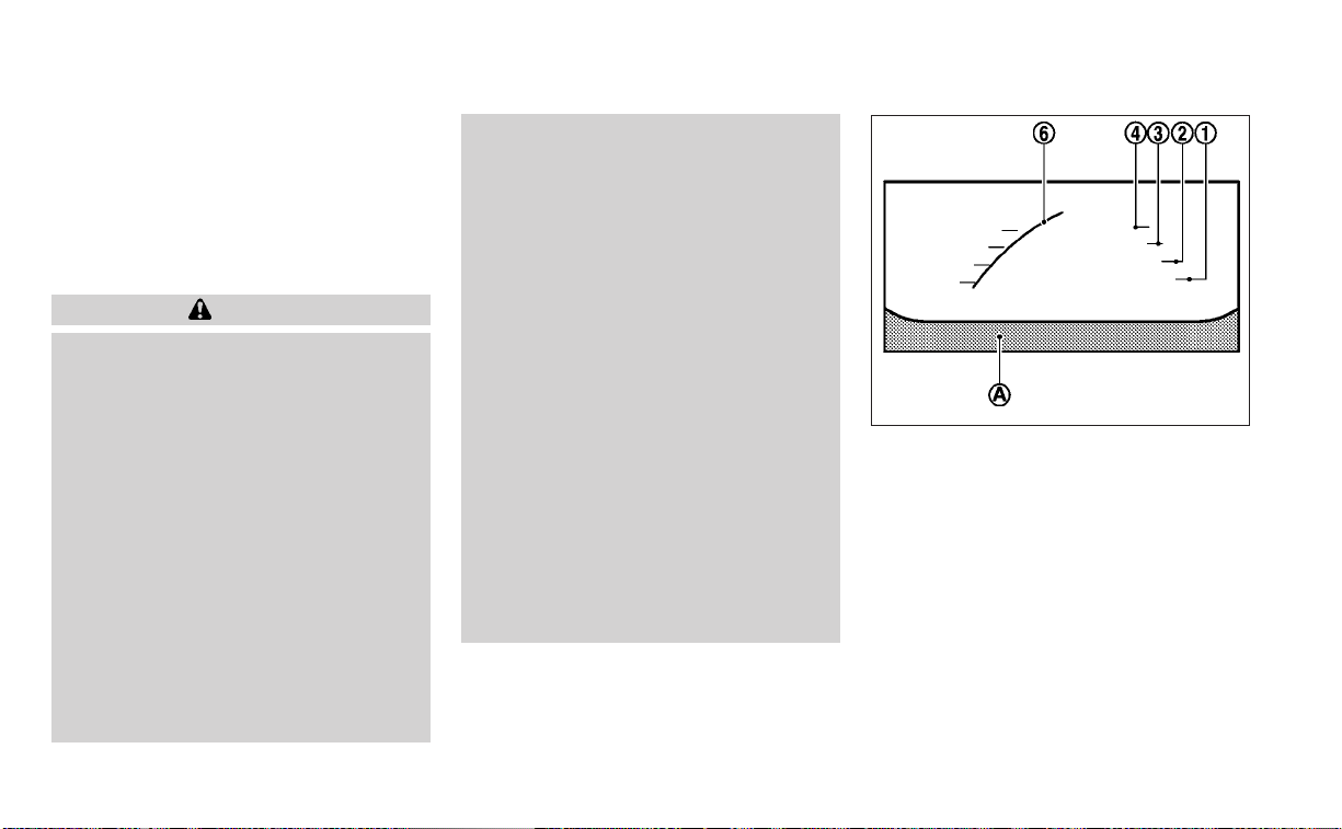
The screen displayed on the Intelligent
Around View Monitor will automatically re-
turn to the previous screen 3 minutes after
the CAMERA button has been pressed with
the shift lever in a position other than the R
(Reverse) position.
Available views
WARNING
• The distance guide lines and the ve-
hicle width lines should be used as a
reference only when the vehicle is on
a paved, level surface. The apparent
distance viewed on the monitor may
be different than the actual distance
between the vehicle and displayed
objects.
• Use the displayed lines and the
bird’s-eye view as a reference. The
lines and the bird’s-eye view are
greatly affected by the number of oc-
cupants, cargo, fuel level, vehicle po-
sition, road condition and road
grade.
• If the tires are replaced with different
sized tires, the predicted course lines
and the bird's-eye view may be dis-
played incorrectly.
• When driving the vehicle up a hill, ob-
jects viewed in the monitor are fur-
ther than they appear. When driving
the vehicle down a hill, objects
viewed in the monitor are closer than
they appear.
• Objects in the rear view will appear
visually opposite compared to when
viewed in the monitor and outside
mirrors.
• Use the mirrors or actually look to
properly judge distances to other
objects.
• On a snow-covered or slippery road,
there may be a difference between
the predicted course lines and the
actual course line.
• The vehicle width and predicted
course lines are wider than the actual
width and course.
• The displayed lines will appear
slightly off to the right, because the
rearview camera is not installed in
the rear center of the vehicle.
Front and rear view
Guiding lines that indicate the approximate
vehicle width and distance to objects with
reference to the vehicle body line
O
A
are
displayed on the monitor.
Distance guide lines:
Indicate distances from the vehicle body:
• Red line
O
1
: approximately 1.5 ft (0.5 m)
• Yellow line
O
2
: approximately 3 ft (1 m)
• Green line
O
3
: approximately 7 ft (2 m)
• Green line
O
4
: approximately 10 ft (3 m) (if
so equipped)
SAA1840
Front view
Monitor, climate, audio, phone and voice recognition systems 4-17

Vehicle width guide lines
O
5
:
Indicate the approximate vehicle width
when backing up.
Predicted course lines
O
6
:
Indicate the predicted course when oper-
ating the vehicle. The predicted course
lines will be displayed on the monitor when
the steering wheel is turned. The predicted
course lines will move depending on how
much the steering wheel is turned and will
not be displayed while the steering wheel is
in the straight-ahead position.
The front view will not be displayed when
the vehicle speed is above 6 mph (10 km/h).
NOTE:
When the monitor displays the front
view and the steering wheel turns about
90 degrees or less from the straight-
ahead position, both the right and left
predicted course lines
O
6
are displayed.
When the steering wheel turns about 90
degrees or more, a line is displayed only
on the opposite side of the turn.
Bird’s-eye view
The bird's-eye view shows the overhead
view of the vehicle, which helps confirm the
vehicle position and the predicted course
to a parking space.
The vehicle icon
O
1
shows the position of
the vehicle. Note that the apparent dis-
tance between objects viewed in the
bird's-eye view may differ somewhat from
the actual distance to the vehicle.
The areas that the cameras cannot cover
O
2
are indicated in black.
LHA4992
Rear view
LHA4264
4-18 Monitor, climate, audio, phone and voice recognition systems

After the ignition switched is placed in the
ON position, the non-viewable area
O
2
is
highlighted in yellow for 3 seconds after the
birds-eye view is displayed.
In addition, the non-viewable corners are
displayed in red and will blink for the first 3
seconds
O
3
to remind the driver to be
cautious.
WARNING
• Objects in the bird's-eye view will ap-
pear further than the actual distance.
• Tall objects, such as a curb or vehicle,
may be misaligned or not displayed
at the seam of the views.
• Objects that are above the camera
cannot be displayed.
• The view of the bird's-eye view may
be misaligned when the camera po-
sition alters.
• A line on the ground may be mis-
aligned and is not seen as being
straight at the seam of the views. The
misalignment will increase as the
line proceeds away from the vehicle.
Front-side view
Guiding lines
Guiding lines that indicate the approximate
width and the front end of the vehicle are
displayed on the monitor.
The front-of-vehicle line
O
1
shows the front
part of the vehicle.
The side-of-vehicle line
O
2
shows the ap-
proximate vehicle width including the out-
side mirrors.
The extensions
O
3
of both the front
O
1
and
side
O
2
lines are shown with a green dotted
line.
DIFFERENCE BETWEEN PREDICTED
AND ACTUAL DISTANCES
The displayed guidelines and their loca-
tions on the ground are for approximate
reference only. Objects on uphill or downhill
surfaces or projecting objects will be actu-
ally located at distances different from
those displayed in the monitor relative to
the guidelines (refer to illustrations). When
in doubt, turn around and view the objects
as you are backing up, or park and exit the
vehicle to view the positioning of objects
behind the vehicle.
LHA2652
Monitor, climate, audio, phone and voice recognition systems 4-19

Backing up on a steep uphill
When backing up the vehicle up a hill, the
distance guide lines and the vehicle width
guide lines are shown closer than the ac-
tual distance. Note that any object on the
hill is further than it appears on the
monitor.
Backing up on a steep downhill
When backing up the vehicle down a hill,
the distance guide lines and the vehicle
width guide lines are shown farther than
the actual distance. Note that any object
on the hill is closer than it appears on the
monitor.
Backing up near a projecting
object
The predicted course lines
O
A
do not touch
the object in the display. However, the ve-
hicle may hit the object if it projects over
the actual backing up course.
LHA5178 LHA4944 LHA4995
4-20 Monitor, climate, audio, phone and voice recognition systems

Backing up behind a projecting
object
The position
O
C
is shown farther than the
position
O
B
in the display. However, the po-
sition
O
C
is actually at the same distance as
the position
O
A
. The vehicle may hit the
object when backing up to the position
O
A
if the object projects over the actual back-
ing up course.
HOW TO PARK WITH PREDICTED
COURSE LINES
WARNING
• If the tires are replaced with different
sized tires, the predicted course lines
may be displayed incorrectly.
• On a snow-covered or slippery road,
there may be a difference between
the predicted course line and the ac-
tual course line.
• If the battery is disconnected or be-
comes discharged, the predicted
course lines may be displayed incor-
rectly. If this occurs, please perform
the following procedures:
– Turn the steering wheel from lock
to lock while the engine is
running.
– Drive the vehicle on a straight road
for more than 5 minutes.
• When the steering wheel is turned
with the ignition switch in the ACC
position, the predicted course lines
may be displayed incorrectly.
1. Visually check that the parking space is
safe before parking your vehicle.
2. The rear view of the vehicle is displayed
on the screen
O
A
when the shift lever is
moved to the R (Reverse) position.
LHA5179 LHA5043
Monitor, climate, audio, phone and voice recognition systems 4-21

3. Slowly back up the vehicle adjusting the
steering wheel so that the predicted
course lines
O
B
enter the parking space
O
C
.
4. Maneuver the steering wheel to make
the vehicle width guide lines
O
D
parallel
to the parking space
O
C
while referring
to the predicted course lines.
5. When the vehicle is parked in the space
completely, move the shift lever to the P
(Park) position and apply the parking
brake.
HOW TO SWITCH THE DISPLAY
With the ignition switch in the ON position,
press the CAMERA button or move the shift
lever to the R (Reverse) position to operate
the Intelligent Around View Monitor.
The Intelligent Around View Monitor dis-
plays different split screen views depend-
ing on the position of the shift lever. Press
the CAMERA button to switch between the
available views.
If the shift lever is in the R (Reverse) position,
the available views are:
• Rear view/bird’s-eye view split screen
• Rear view/front-side view split screen
• Full screen rear view
If the shift lever is in the P (Park) or D (Drive)
position, the available views are:
• Front view/bird’s-eye view split screen
• Front view/front-side view split screen
The display will switch from the Intelligent
Around View Monitor screen when:
• The shift lever is in the D (Drive) position
and the vehicle speed increases above
approximately 6 mph (10 km/h)
• A different screen is selected.
LHA4770
4-22 Monitor, climate, audio, phone and voice recognition systems

ADJUSTING THE SCREEN
1. While on the main menu screen, touch
the “Settings” key.
2. Use the arrow to tab to the next screen
and touch the “Camera” key.
3. Touch the “Display Settings” key.
4. Touch the “Brightness”, “Contrast”, Tint”,
“Color”, or “Black Level” key.
5. Adjust the item by touching the “+” or “–”
key on the touch-screen display.
NOTE:
Do not adjust any of the display settings
of the Intelligent Around View Monitor
while the vehicle is moving. Make sure
the parking brake is firmly applied.
INTELLIGENT AROUND VIEW
MONITOR SYSTEM LIMITATIONS
LHA3522
LHA5326
Monitor, climate, audio, phone and voice recognition systems 4-23

WARNING
Listed below are the system limitations
for Intelligent Around View Monitor.
Failure to operate the vehicle in accor-
dance with these system limitations
could result in serious injury or death.
• Do not use the Intelligent Around
View Monitor with the outside mir-
rors in the stored position, and make
sure that the trunk is securely closed
when operating the vehicle using the
Intelligent Around View Monitor.
• The apparent distance between ob-
jects viewed on the Intelligent
Around View Monitor differs from the
actual distance.
• The cameras are installed on the
front grille, the outside mirrors and
above the rear license plate. Do not
put anything such as a license plate
frame on the vehicle that covers or
blocks the view of the cameras.
• When washing the vehicle with high
pressure water, be sure not to spray it
around the cameras. Otherwise, wa-
ter may enter the camera unit caus-
ing water condensation on the lens, a
malfunction, fire or an electric shock.
• Do not strike the cameras. They are
precision instruments. Doing so
could cause a malfunction or cause
damage resulting in a fire or an elec-
tric shock.
There are some areas where the system
will not show objects and the system does
not warn of moving objects. When in the
front or rear view display, an object below
the bumper or on the ground may not be
viewed
O
1
. When in the bird’s-eye view, a tall
object near the seam
O
2
of the camera
viewing areas will not appear in the
monitor.
The following are operating limitations and
do not represent a system malfunction:
• There may be a delay when switching
between views.
• When the temperature is extremely high
or low, the screen may not display objects
clearly.
• When strong light directly shines on the
camera, objects may not be displayed
clearly.
• The screen may flicker under fluorescent
light.
• The colors of objects on the Intelligent
Around View Monitor may differ some-
what from the actual color of objects.
• Objects on the Intelligent Around View
Monitor may not be clear and the color of
the object may differ in a dark
environment.
• There may be differences in sharpness
between each camera view of the bird's-
eye view .
• Do not use wax on the camera lens. Wipe
off any wax with a clean cloth that has
been dampened with a diluted mild
cleaning agent, then wipe with a dry
cloth.
4-24 Monitor, climate, audio, phone and voice recognition systems

System temporarily unavailable
When the “!” icon is displayed on the screen,
there are abnormal conditions in the Intel-
ligent Around View Monitor. This will not
hinder normal driving operation but the
system should be inspected. It is recom-
mended that you visit a NISSAN dealer for
this service.
When the “[X ]” icon is displayed on the
screen, the camera image may be receiv-
ing temporary electronic disturbances
from surrounding devices. This will not hin-
der normal driving operation but the sys-
tem should be inspected if it occurs fre-
quently. It is recommended that you visit a
NISSAN dealer for this service.
SYSTEM MAINTENANCE
CAUTION
• Do not use alcohol, benzine or thin-
ner to clean the camera. This will
cause discoloration.
• Do not damage the cameras as the
monitor screen may be adversely
affected.
If dirt, rain or snow accumulates on any of the
cameras
O
1
, the Intelligent Around View
Monitor may not display objects clearly.
Clean the camera by wiping with a cloth
dampened with a diluted mild cleaning agent
and then wiping with a dry cloth.
LHA3591 LHA3592 LHA5325
Monitor, climate, audio, phone and voice recognition systems 4-25

1. CAMERA button
LHA4800
MOVING OBJECT DETECTION (MOD)
(if so equipped)
4-26 Monitor, climate, audio, phone and voice recognition systems

WARNING
Failure to follow the warnings and in-
structions for proper use of the Moving
Object Detection (MOD) system could
result in serious injury or death
• The MOD system is not a substitute
for proper vehicle operation and is
not designed to prevent contact with
objects surrounding the vehicle.
When maneuvering, always use the
outside mirrors and rearview mirror
and turn and check the surroundings
to ensure it is safe to maneuver.
• The system is deactivated at speeds
above 5 mph (8 km/h). It is reacti-
vated at lower speeds.
• The MOD system is not designed to
detect surrounding stationary
objects.
The MOD system can inform the driver of
moving objects near the vehicle when
backing out of garages, maneuvering in
parking lots and in other such instances.
The MOD system detects moving objects
by using image processing technology on
the image shown in the display.
MOD SYSTEM OPERATION
The MOD system will turn on automatically
under the following conditions:
• When the shift lever is in the R (Reverse)
position.
• When the CAMERA button is pressed to
activate the camera view on the display.
• When vehicle speed decreases below ap-
proximately 6 mph (10 km/h) and the
camera screen is displayed.
The MOD system operates in the following
conditions when the camera view is
displayed:
• When the shift lever is in the P (Park) or N
(Neutral) position and the vehicle is
stopped, the MOD system detects mov-
ing objects in the bird’s-eye view. The
MOD system will not operate if the out-
side mirrors are moving in or out, in the
stowed position, or if either front door is
opened.
LHA4190
Front and bird’s-eye views
Monitor, climate, audio, phone and voice recognition systems 4-27

• When the shift lever is in the D (Drive)
position and the vehicle speed is below
approximately 6 mph (10 km/h), the MOD
system detects moving objects in the
front view.
• When the shift lever is in the R (Reverse)
position and the vehicle speed is below
approximately 6 mph (10 km/h), the MOD
system detects moving objects in the
rear view. The MOD system will not oper-
ate if the trunk is open.
The MOD system does not detect moving
objects in the front-side view. The MOD
icon is not displayed on the screen when in
this view.
When the MOD system detects moving ob-
jects near the vehicle, a chime will be heard
when in front or rear view and a yellow
frame will be displayed on the view where
the objects are detected. While the MOD
system continues to detect moving ob-
jects, the yellow frame continues to be
displayed.
NOTE:
While the RCTA chime is beeping, the
MOD system does not chime.
In the bird’s-eye view, the yellow frame
O
1
is
displayed on each camera image (front,
rear, right, left) depending on where mov-
ing objects are detected.
The yellow frame
O
2
is displayed on each
view in the front view and rear view modes.
A blue MOD icon
O
3
is displayed in the view
where the MOD system is operative. A gray
MOD icon is displayed in the view where the
MOD system is not operative.
LHA5171
Rear and bird’s-eye views
LHA4997
Rear and front-side views
LHA4998
Full screen rear view
4-28 Monitor, climate, audio, phone and voice recognition systems

If the MOD system is turned off, the MOD
icon
O
3
is not displayed.
TURNING MOD ON AND OFF (if so
equipped)
Some vehicles include the option to allow
the MOD system to be turned on or off.
To turn the MOD system on or off:
1. Touch the “Setting” key.
2. Touch the “Camera” key.
3. Touch the “Moving Object Detection” key
to switch between ON or OFF.
MOD SYSTEM LIMITATIONS
WARNING
Listed below are the system limitations
for MOD. Failure to operate the vehicle
in accordance with these system limi-
tations could result in serious injury or
death.
• Do not use the MOD system when
towing a trailer. The system may not
function properly.
• Excessive noise (for example, audio
system volume or open vehicle win-
dow) will interfere with the chime
sound, and it may not be heard.
• The MOD system performance will be
limited according to environmental
conditions and surrounding objects
such as:
– When there is low contrast be-
tween background and the mov-
ing objects.
– When there is a blinking source of
light.
– When strong light such as another
vehicle’s headlight or sunlight is
present.
– When camera orientation is not in
its usual position, such as when a
mirror is folded.
– When there is dirt, water drops or
snow on the camera lens.
– When the position of the moving
objects in the display is not
changed.
• The MOD system might detect flow-
ing water droplets on the camera
lens, white smoke from the muffler,
moving shadows, etc.
• The MOD system may not function
properly depending on the speed, di-
rection, distance or shape of the
moving objects.
• If your vehicle sustains damage to
the parts where the camera is in-
stalled, leaving it misaligned or bent,
the sensing zone may be altered and
the MOD system may not detect ob-
jects properly.
• When the temperature is extremely
high or low, the screen may not dis-
play objects clearly. This is not a
malfunction.
NOTE:
The blue MOD icon will change to orange
if one of the following has occurred:
• When the system is malfunctioning.
• When the component temperature
reaches a high level (icon will blink).
• When the RearView camera has detected
a blockage (icon will blink).
If the icon light continues to illuminate
orange, have the MOD system checked. It
is recommended that you visit a NISSAN
dealer for this service.
Monitor, climate, audio, phone and voice recognition systems 4-29

SYSTEM MAINTENANCE
CAUTION
• Do not use alcohol, benzine or thin-
ner to clean the camera. This will
cause discoloration.
• Do not damage the camera as the
monitor screen may be adversely
affected.
If dirt, rain or snow accumulates on any of
the cameras
O
1
, the MOD system may not
operate properly. Clean the camera by wip-
ing with a cloth dampened with a diluted
mild cleaning agent and then wiping with a
dry cloth.
Adjust air flow direction by moving the vent
slides.
Open or close the vents by using the slide.
Move the slide toward the
to open the
vents or toward the
to close them.
LHA5325 LHA4940
Side
VENTS
4-30 Monitor, climate, audio, phone and voice recognition systems
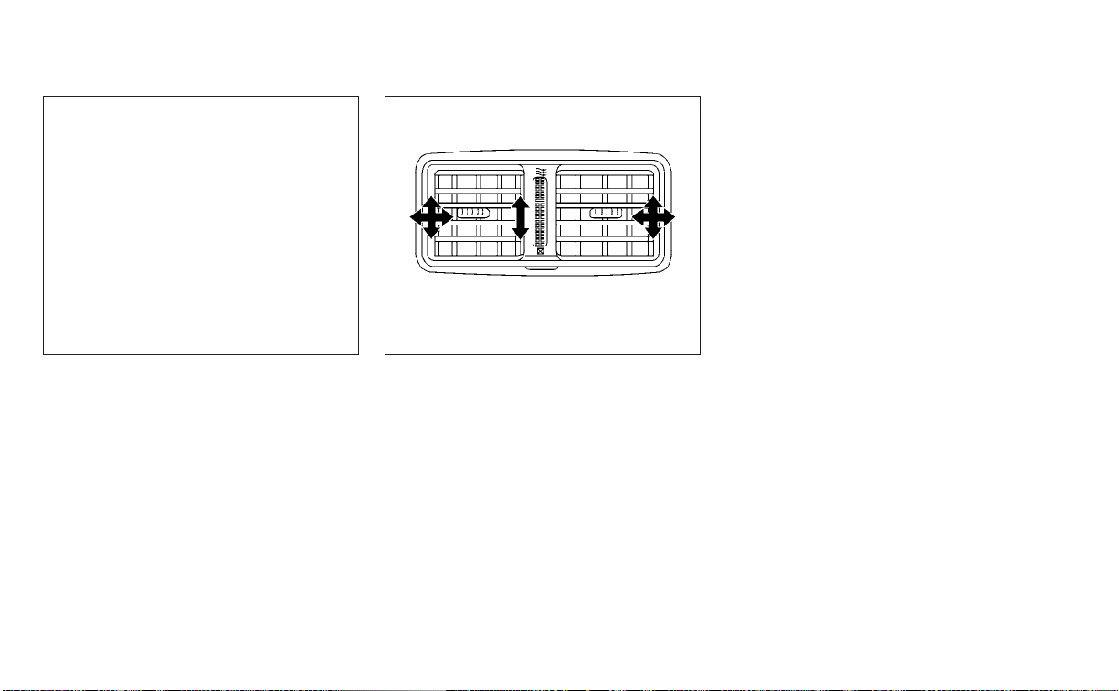
LHA4939
Center
LHA1134
Rear (if so equipped)
Monitor, climate, audio, phone and voice recognition systems 4-31

1. Fan speed control dial
2.
Heated seat switches (if so
equipped)
3.
Front defroster button
4.
Rear window and outside mirror
(if so equipped) defroster switch
5.
Air recirculation button
6. MAX A/C / temperature control dial
7. Air flow control buttons
8. A/C (air conditioner) button
WARNING
• The air conditioner cooling function
operates only when the engine is
running.
• Do not leave children or adults who
would normally require the assis-
tance of others alone in your vehicle.
Pets should also not be left alone.
They could accidentally injure them-
selves or others through inadvertent
operation of the vehicle. Also, on hot,
sunny days, temperatures in a closed
vehicle could quickly become high
enough to cause severe or possibly
fatal injuries to people or animals.
• Do not use the recirculation mode for
long periods as it may cause the inte-
rior air to become stale and the win-
dows to fog up.
NOTE:
• Odors from inside and outside the ve-
hicle can build up in the air conditioner
unit. Odor can enter the passenger
compartment through the vents.
• When parking, set the heater and air
conditioner controls to turn off air re-
circulation to allow fresh air into the
passenger compartment. This should
help reduce odors inside the vehicle.
LHA4783
HEATER AND AIR CONDITIONER
(manual) (if so equipped)
4-32 Monitor, climate, audio, phone and voice recognition systems
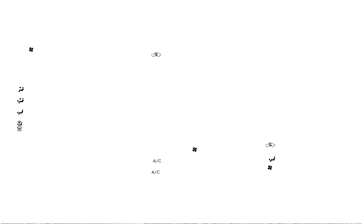
CONTROLS
Fan speed control dial
The fan speed control dial turns the
fan on and off and controls fan speed.
Air flow control buttons
The air flow control buttons allow you to
select the air flow outlets.
— Air flows from center and side
vents.
— Air flows from center and side
vents and foot outlets.
— Air flows mainly from foot outlets.
— Air flows from defroster outlets
and foot outlets.
— Air flows mainly from defroster
outlets.
Temperature control dial
The temperature control dial allows you to
adjust the temperature of the outlet air. To
lower the temperature, turn the dial to the
left. To increase the temperature, turn the
dial to the right.
Turn the dial to the MAX A/C position for
maximum cooling. Air will flow from center
and side vents.
Air recirculation button
On position (Indicator light on):
Interior air is recirculated inside the vehicle.
Press the
button to the on position
when:
• driving on a dusty road.
• to prevent traffic fumes from entering
passenger compartment.
• for maximum cooling when using the air
conditioner.
Off position (Indicator light off):
Outside air is drawn into the passenger
compartment and distributed through the
selected outlet.
Use the off position for normal heater or air
conditioner operation.
A/C (air conditioner) button
Start the engine, turn the fan speed
control dial to the desired position and
press the
button to turn on the air
conditioner. To turn off the air conditioner,
press the
button again.
The air conditioner cooling function op-
erates only when the engine is running.
Rear window and outside mirror
(if so equipped) defroster switch
For additional information, see “Rear win-
dow and outside mirror (if so equipped)
defroster switch” (P. 2-54).
Heated seat switches (if so
equipped)
For additional information, see “Heated
seat switches” (P. 2-62).
HEATER OPERATION
Heating
This mode is used to direct heated air to
the foot outlets. Some air also flows from
the defrost outlets and the side vent
outlets.
1. Press the
button to the off position
for normal heating.
2. Press the
air flow control button.
3. Turn the
fan speed control dial to
the desired position.
4. Turn the temperature control dial to the
desired position between the middle
and the hot position.
Monitor, climate, audio, phone and voice recognition systems 4-33

Ventilation
This mode directs outside air to the side
and center vents.
1. Press the
button to the off position.
2. Press the
air flow control button.
3. Turn the
fan speed control dial to
the desired position.
4. Turn the temperature control dial to the
desired position.
Defrosting or defogging
This mode directs the air to the defrost
outlets to defrost/defog the windows.
1. Press the defrost/defog button
.
2. Turn the
fan speed control dial to
the desired position.
3. Turn the temperature control dial to the
desired position between the middle
and the hot position.
• To quickly remove ice or fog from the win-
dows, turn the
fan speed control dial
to the highest setting and the tempera-
ture control to the full HOT position.
• When the
position is selected, the air
conditioner automatically turns on if the
outside temperature is more than 36°F
(2°C). This dehumidifies the air which
helps defog the windshield. The
mode automatically turns off, allowing
outside air to be drawn into the passen-
ger compartment to further improve the
defogging performance. The recircula-
tion mode cannot be activated in the
position.
Bi-level heating
The bi-level mode directs warmed air to
the side and center vents and to the front
and rear floor outlets.
1. Press the
button to the off position.
2. Press the
air flow control button.
3. Turn the
fan speed control dial to
the desired position.
4. Turn the temperature control dial to the
desired position.
Heating and defogging
This mode heats the interior and defogs
the windshield.
1. Press the
air flow control button.
2. Turn the
fan speed control dial to
the desired position.
3. Turn the temperature control dial to the
desired position between the middle
and the hot position.
• When the
position is selected, the
air conditioner automatically turns on if
the outside temperature is more than
36°F (2°C). This dehumidifies the air which
helps defog the windshield. The
mode automatically turns off, allowing
outside air to be drawn into the passen-
ger compartment to further improve the
defogging performance.
Operating tips
Clear snow and ice from the wiper blades
and air inlet in front of the windshield.
This improves heater operation.
AIR CONDITIONER OPERATION
Start the engine, turn the fan speed
control dial to the desired position, and
press the
button to activate the air
conditioner. When the air conditioner is on,
cooling and dehumidifying functions are
added to the heater operation.
The air conditioner cooling function op-
erates only when the engine is running.
4-34 Monitor, climate, audio, phone and voice recognition systems

Cooling
This mode is used to cool and dehumidify
the air.
1. Press the
button to the off position.
2. Press the
air flow control button.
3. Turn the
fan speed control dial to
the desired position.
4. Press the A/C button. The indicator light
comes on.
5. Turn the temperature control dial to the
desired position.
• For quick cooling when the outside tem-
perature is high, press the
button to
the ON position. Be sure to return the
to the off position for normal cooling.
MAX A/C may be used for quick cooling.
Dehumidified heating
This mode is used to heat and dehumidify
the air.
1. Press the
button to the off position.
2. Press the
air flow control button.
3. Turn the
fan speed control dial to
the desired position.
4. Press the A/C (air conditioner) button.
The indicator light comes on.
5. Turn the temperature control dial to the
desired position.
Dehumidified defogging
This mode is used to defog the windows
and dehumidify the air.
1. Press the
air flow control button.
2. Turn the
fan speed control dial to
the desired position.
• When the
or are selected, the
air conditioner automatically turns on if
the outside temperature is more than
36°F (2°C). This dehumidifies the air which
helps defog the windshield. The
mode automatically turns off, allowing
outside air to be drawn into the passen-
ger compartment to further improve the
defogging performance.
3. Turn the temperature control dial to the
desired position.
Operating tips
• Keep the windows closed while the air
conditioner is in operation.
• After parking in the sun, drive for 2 or 3
minutes with the windows open to vent
hot air from the passenger compart-
ment. Then, close the windows. This al-
lows the air conditioner to cool the inte-
rior more quickly.
• The air conditioning system should be
operated for approximately 10 minutes at
least once a month. This helps prevent
damage to the system due to lack of
lubrication.
• A visible mist may be seen coming from
the ventilators in hot, humid conditions
as the air is cooled rapidly. This does not
indicate a malfunction.
• If the engine coolant temperature gauge
indicates engine coolant temperature
over the normal range, turn the air condi-
tioner off. For additional information, see
“If your vehicle overheats” (P. 6-13).
• When Remote Engine Start (if so
equipped) is activated, the manual cli-
mate control system will default to the
last used heating or cooling mode.
AIR FLOW CHARTS
The following charts show the button and
dial positions for MAXIMUM AND QUICK
heating, cooling or defrosting. The
air
recirculation button should always be in
the off position for heating and
defrosting.
Monitor, climate, audio, phone and voice recognition systems 4-35

LHA4786 LHA4787
4-36 Monitor, climate, audio, phone and voice recognition systems

LHA4788 LHA4789
Monitor, climate, audio, phone and voice recognition systems 4-37

LHA4790
4-38 Monitor, climate, audio, phone and voice recognition systems
1. AUTO (automatic) climate control but-
ton / temperature control dial (drivers
side)
2. Display screen
3.
Heated seat switches
4. SYNC button / temperature control dial
(passenger’s side)
5. A/C (air conditioner) button
6.
Air recirculation button
7.
Air flow control button
8.
Fan speed control buttons
9.
Heated steering wheel switch
10.
Rear window and outside mirror
defroster switch
11.
Front defroster button
12. ON-OFF button
WARNING
• The air conditioner cooling function
operates only when the engine is
running.
• Do not leave children or adults who
would normally require the assis-
tance of others alone in your vehicle.
Pets should also not be left alone.
They could accidentally injure them-
selves or others through inadvertent
operation of the vehicle. Also, on hot,
sunny days, temperatures in a closed
vehicle could quickly become high
enough to cause severe or possibly
fatal injuries to people or animals.
• Do not use the recirculation mode for
long periods as it may cause the inte-
rior air to become stale and the win-
dows to fog up.
Start the engine and operate the controls
to activate the air conditioner.
LHA4784
HEATER AND AIR CONDITIONER
(automatic) (if so equipped)
Monitor, climate, audio, phone and voice recognition systems 4-39

NOTE:
• Odors from inside and outside the ve-
hicle can build up in the air conditioner
unit. Odor can enter the passenger
compartment through the vents.
• When parking, set the heater and air
conditioner controls to turn off air re-
circulation to allow fresh air into the
passenger compartment. This should
help reduce odors inside the vehicle.
AUTOMATIC OPERATION
Cooling and/or dehumidified
heating (AUTO)
This mode may be used all year round as
the system automatically works to keep a
constant temperature. Air flow distribution,
air intake control, and fan speed are also
controlled automatically.
1. Press the AUTO button on.
2. Turn the temperature control dial to the
left or right to set the desired
temperature.
• Adjust the temperature display to about
75°F (24°C) for normal operation.
• The temperature of the passenger com-
partment will be maintained automati-
cally. Air flow distribution, air intake con-
trol and fan speed are also controlled
automatically.
• A visible mist may be seen coming from
the vents in hot, humid conditions as the
air is cooled rapidly. This does not indicate
a malfunction.
3. You can individually set driver's and front
passenger's side temperature using
each temperature control dial. To syn-
chronize the driver’s and front passen-
ger’s temperature settings, press the
SYNC button.
Heating (A/C OFF)
The air conditioner does not activate. When
you need to heat only, use this mode.
1. Press the AUTO button.
2. Turn the temperature control dial to set
the desired temperature.
• The temperature of the passenger com-
partment will be maintained automati-
cally. Air flow distribution and fan speed
are also controlled automatically.
• Do not set the temperature lower than
the outside air temperature. Otherwise,
the system may not work properly.
• Not recommended if windows fog up.
Dehumidified defrosting or
defogging
1. Press the front defroster button on.
2. Turn the temperature control dial to set
the desired temperature.
• To quickly remove ice from the outside of
the windows, use the
fan speed con-
trol buttons to set the fan speed to
maximum.
• As soon as possible after the windshield
is clean, press the AUTO button to return
to the automatic mode.
• When the
front defroster button is
pressed, the air conditioner will automati-
cally be turned on at outside tempera-
tures above 36°F (2°C). The air recirculate
mode automatically turns off, allowing
outside air to be drawn into the passen-
ger compartment to further improve the
defogging performance.
4-40 Monitor, climate, audio, phone and voice recognition systems

Remote Engine Start with
Intelligent Climate Control (if so
equipped)
Vehicles equipped with automatic climate
controls and Remote Engine Start function
may go into automatic heating or cooling
mode when Remote Engine Start is acti-
vated depending on outside and cabin
temperatures. During this period, the cli-
mate control display and buttons will be
inoperable until the ignition switch is
turned on. In Remote Engine Start defrost-
ing mode, the rear window defroster,
heated seats (if so equipped) and heated
steering wheel (if so equipped) may be ac-
tivated automatically.
MANUAL OPERATION
Fan speed control buttons
Press the fan speed control buttons
to manually control the fan speed.
Press the AUTO button to return to auto-
matic control of the fan speed.
Temperature control dial
The temperature control dial allows you to
adjust the temperature of the outlet air. To
lower the temperature, turn the dial to the
left. To increase the temperature, turn the
dial to the right. Temperature can be ad-
justed on the driver’s and passenger’s side.
Air recirculation
Press the air recirculation button to
recirculate interior air inside the vehicle.
The
indicator light on the button will
come on.
The air recirculation cannot be activated
when the air conditioner is in the
front
defrosting mode.
When the outside temperature exceeds
70°F (21°C), the air conditioning system may
default to air recirculation mode automati-
cally to reduce overall power consumption.
To exit air recirculation mode, deselect the
air recirculation button (indicator light will
turn off) to enter fresh air mode.
Automatic intake air control
In the AUTO mode, the intake air will be
controlled automatically. To manually con-
trol the intake air, press the
air recir-
culation button. To return to the automatic
control mode, press and hold the
air
recirculation button for about 2 seconds.
The indicator light will flash twice, and then
the intake air will be controlled
automatically.
A/C (air conditioner) button
Start the engine, press the fan speed
control buttons to the desired position and
press the
button to turn on the air
conditioner. To turn off the air conditioner,
press the
button again.
The air conditioner cooling function op-
erates only when the engine is running.
Monitor, climate, audio, phone and voice recognition systems 4-41

Air flow control
Pressing the button manually con-
trols air flow and selects the air outlet:
— Air flows from center and side
vents.
— Air flows from center and side
vents and foot outlets.
— Air flows mainly from the foot
outlets.
— Air flows from defroster and foot
outlets.
Synchronize climate settings
Press the SYNC button to synchronize cli-
mate settings. The sync indicator will turn
on.
Pressing SYNC will synchronize driver's and
front passenger's climate settings.
To change climate settings when SYNC is
active (the SYNC indicator is on):
• The driver's side temperature control dial
will control the driver and front passenger
temperatures.
• The fan speed control dial will control the
fan speeds.
To exit SYNC:
• To remove the front passenger from
SYNC, turn the passenger's side tem-
perature control dial.
• Pressing SYNC multiple times will re-
activate SYNC.
To turn system off
Press the ON-OFF button.
Rear window and outside mirror
defroster switch
For additional information, see “Rear win-
dow and outside mirror (if so equipped)
defroster switch” (P. 2-54).
Heated seat switches
For additional information, see “Heated
seat switches (if so equipped)” (P. 2-62).
Heated steering wheel switch
For additional information, see “Heated
steering wheel switch (if so equipped)”
(P. 2-63).
OPERATING TIPS
The sunload sensor, located on the top
center of the instrument panel, helps the
system maintain a constant temperature.
Do not put anything on or around this
sensor.
LHA4943
4-42 Monitor, climate, audio, phone and voice recognition systems

• When the climate system is in automatic
operation and the engine coolant tem-
perature and outside air temperature are
low, the air flow outlet may default to de-
froster mode for a maximum of 2 min-
utes 30 seconds. This is not a malfunc-
tion. After the engine coolant
temperature warms up, the air flow outlet
will return to foot mode and operation will
continue normally.
• When the outside and interior cabin tem-
peratures are moderate to high, the in-
take setting may default to turn off air
recirculation to allow fresh air into the
passenger compartment. You may no-
tice air flow from the foot mode, bi-level
mode, or side demist vent outlets for a
maximum of 15 seconds. This may occur
when the previous climate setting was
turned off. This is not a malfunction. After
the initial warm air is expelled, the intake
will return to automatic control, the air
flow outlet will return to previous settings,
and operation will continue normally. To
exit, press any climate control button.
• Keep the moonroof (if so equipped)
closed while the air conditioner is in
operation.
• If you feel that the air flow mode you have
selected and the outlets the air is coming
out do not match, select the
mode.
• When you change the air flow mode, you
may feel air flow from the foot outlets for
just a moment. This is not a malfunction.
The air conditioner system in your NISSAN
vehicle is charged with a refrigerant de-
signed with the environment in mind.
This refrigerant does not harm the
earth's ozone layer.
Special charging equipment and lubricant
is required when servicing your NISSAN air
conditioner. Using improper refrigerants or
lubricants will cause severe damage to
your air conditioner system. For additional
information, see “Air conditioner system re-
frigerant and oil recommendations”
(P. 10-8).
It is recommended that you visit a NISSAN
dealer to service your “environmentally
friendly” air conditioner system.
WARNING
The air conditioner system contains re-
frigerant under high pressure. To avoid
personal injury, any air conditioner ser-
vice should be done only by an experi-
enced technician with proper
equipment.
SERVICING AIR CONDITIONER
Monitor, climate, audio, phone and voice recognition systems 4-43

RADIO
Place the ignition switch in the ACC or ON
position and press the PUSH
button to
turn the radio on. If you listen to the radio
with the engine not running, the ignition
switch should be placed in the ACC position.
Radio reception is affected by station sig-
nal strength, distance from radio transmit-
ter, buildings, bridges, mountains and other
external influences. Intermittent changes
in reception quality normally are caused by
these external influences.
Using a cellular phone in or near the vehicle
may influence radio reception quality.
Radio reception
Your NISSAN radio system is equipped with
state-of-the-art electronic circuits to en-
hance radio reception. These circuits are
designed to extend reception range, and to
enhance the quality of that reception.
However, there are some general charac-
teristics of both FM and AM radio signals
that can affect radio reception quality in a
moving vehicle, even when the finest
equipment is used. These characteristics
are completely normal in a given reception
area and do not indicate any malfunction
in your NISSAN radio system.
Reception conditions will constantly
change because of vehicle movement.
Buildings, terrain, signal distance and inter-
ference from other vehicles can work
against ideal reception. Described below
are some of the factors that can affect your
radio reception.
Some cellular phones or other devices may
cause interference or a buzzing noise to
come from the audio system speakers.
Storing the device in a different location
may reduce or eliminate the noise.
FM RADIO RECEPTION
Range: FM range is normally limited to 25 –
30 mi (40 – 48 km), with monaural (single
channel) FM having slightly more range
than stereo FM. External influences may
sometimes interfere with FM station re-
ception even if the FM station is within 25
mi (40 km). The strength of the FM signal is
directly related to the distance between
the transmitter and receiver. FM signals fol-
low a line-of-sight path, exhibiting many of
the same characteristics as light. For ex-
ample, they will reflect off objects.
Fade and drift: As your vehicle moves away
from a station transmitter, the signals will
tend to fade and/or drift.
Static and flutter: During signal interfer-
ence from buildings, large hills or due to
antenna position (usually in conjunction
with increased distance from the station
transmitter), static or flutter can be heard.
This can be reduced by adjusting the treble
control to reduce treble response.
Multipath reception: Because of the reflec-
tive characteristics of FM signals, direct and
reflected signals reach the receiver at the
same time. The signals may cancel each
other, resulting in momentary flutter or loss
of sound.
AM RADIO RECEPTION
AM signals, because of their low frequency,
can bend around objects and skip along
the ground. In addition, the signals can be
bounced off the ionosphere and bent back
to earth. Because of these characteristics,
AM signals are also subject to interference
as they travel from transmitter to receiver.
Fading: Occurs while the vehicle is passing
through freeway underpasses or in areas
with many tall buildings. It can also occur
for several seconds during ionospheric tur-
bulence even in areas where no obstacles
exist.
AUDIO SYSTEM
4-44 Monitor, climate, audio, phone and voice recognition systems

Static: Caused by thunderstorms, electrical
power lines, electric signs and even traffic
lights.
AUDIO OPERATION PRECAUTIONS
MP3 or WMA terms
• MP3 — MP3 is short for Moving Pictures
Experts Group Audio Layer 3. MP3 is the
most well-known compressed digital au-
dio file format. This format allows for near
“CD quality” sound, but at a fraction of the
size of normal audio files. MP3 conversion
of an audio track from CD-ROM can re-
duce the file size by approximately a 10:1
ratio with virtually no perceptible loss in
quality. MP3 compression removes the
redundant and irrelevant parts of a
sound signal that the human ear doesn’t
hear.
• WMA — Windows Media Audio (WMA)* is a
compressed audio format created by Mi-
crosoft as an alternative to MP3. The WMA
codec offers greater file compression
than the MP3 codec, enabling storage of
more digital audio tracks in the same
amount of space when compared to
MP3s at the same level of quality.
• Bit rate — Bit rate denotes the number of
bits per second used by a digital music
file. The size and quality of a compressed
digital audio file is determined by the bit
rate used when encoding the file.
• Sampling frequency — Sampling fre-
quency is the rate at which the samples
of a signal are converted from analog to
digital (A/D conversion) per second.
• Multisession — Multisession is one of the
methods for writing data to media. Writ-
ing data once to the media is called a
single session, and writing more than
once is called a multisession.
• ID3/WMA Tag — The ID3/WMA tag is the
part of the encoded MP3 or WMA file that
contains information about the digital
music file such as song title, artist, encod-
ing bit rate, track time duration, etc. ID3
tag information is displayed on the Artist/
song title line on the display.
* Windows® and Windows Media® are reg-
istered trademarks and trademarks in the
United States of America and other coun-
tries of Microsoft Corporation of the USA.
USB (Universal Serial Bus)
Connection Port
WARNING
• Do not connect, disconnect or oper-
ate the USB device while driving. Do-
ing so can be a distraction. If dis-
tracted you could lose control of your
vehicle and cause an accident or se-
rious injury.
CAUTION
• Do not force the USB device into the
USB port. Inserting the USB device
tilted or up-side-down into the port
may damage the port. Make sure
that the USB device is connected cor-
rectly into the USB port.
• Do not grab the USB port cover (if so
equipped) when pulling the USB de-
vice out of the port. This could dam-
age the port and the cover.
• Do not leave the USB cable in a place
where it can be pulled unintention-
ally. Pulling the cable may damage
the port.
Monitor, climate, audio, phone and voice recognition systems 4-45

The vehicle is not equipped with a USB de-
vice. USB devices should be purchased
separately as necessary.
This system cannot be used to format USB
devices. To format a USB device, use a per-
sonal computer.
In some jurisdictions, the USB device for the
front seats plays only sound without im-
ages for regulatory reasons, even when the
vehicle is parked.
This system supports various USB
memory devices, USB hard drives and
iPod® players. Some USB devices may not
be supported by this system.
• Partitioned USB devices may not play
correctly.
• Some characters used in other lan-
guages (Chinese, Japanese, etc.) may not
appear properly in the display. Using Eng-
lish language characters with a USB de-
vice is recommended.
General notes for USB use:
• For additional information, refer to your
device manufacturer’s owner informa-
tion regarding the proper use and care of
the device.
Notes for iPod® use:
iPod® is a trademark of Apple Inc., regis-
tered in the U.S. and other countries.
• Improperly plugging in the iPod® may
cause a checkmark to be displayed on
and off (flickering). Always make sure that
the iPod® is connected properly.
• An iPod® nano (1st Generation) may re-
main in fast forward or rewind mode if it is
connected during a seek operation. In
this case, please manually reset the
iPod®.
• An iPod® nano (2nd Generation) will con-
tinue to fast-forward or rewind if it is dis-
connected during a seek operation.
• An incorrect song title may appear when
the Play Mode is changed while using an
iPod® nano (2nd Generation).
• Audiobooks may not play in the same
order as they appear on an iPod®.
• Large video files cause slow responses in
an iPod®. The vehicle center display may
momentarily black out, but will soon
recover.
• If an iPod® automatically selects large
video files while in the shuffle mode, the
vehicle center display may momentarily
black out, but will soon recover.
iPod®* player
• Some characters used in other lan-
guages (Chinese, Japanese, etc.) are not
displayed properly on the vehicle center
screen. We recommend using English or
Spanish language characters with an
iPod®.
• Large video podcast files cause slow re-
sponses in the iPod®. The vehicle center
display may momentarily black out, but it
will soon recover.
• If the iPod® automatically selects large
video podcast files while in the shuffle
mode, the vehicle center display may
momentarily black out, but it will soon
recover.
• Improperly plugging in the iPod® may
cause a checkmark to be displayed on
and off (flickering). Always make sure that
the iPod® is connected properly.
• The iPod® nano (2nd Generation) will con-
tinue to fast forward or rewind if it is dis-
connected during a seek operation.
• An incorrect song title may appear when
the Play Mode is changed while using the
iPod® nano (2nd Generation).
• Audiobooks may not play in the same
order as they appear on the iPod®.
4-46 Monitor, climate, audio, phone and voice recognition systems

• The iPod® nano (1st Generation) may re-
main in fast forward or rewind mode if it is
connected during a seek operation. In
this case, please manually reset the
iPod®.
• If you are using an iPod® (3rd Generation
with Dock connector), do not use very
long names for the song title, album
name or artist name to prevent the iPod®
from resetting itself.
• Be careful not to do the following, or the
cable could be damaged and a loss of
function may occur:
– Bend the cable excessively (1.6 in (40
mm) radius maximum).
– Twist the cable excessively (more than
180 degrees).
– Pull or drop the cable.
– Do not force the iPod® cable connector
into the device port.
– Close the center console lid on the
cable or connectors.
– Store objects with sharp edges in the
storage where the cable is stored.
– Spill liquids on the cable and
connectors.
• Do not connect the cable to the iPod® if
the cable and/or connectors are wet. It
may damage the iPod®.
• If the cable and connectors are exposed
to water, allow the cable and/or connec-
tors to dry completely before connecting
the cable to the iPod® (wait 24 hours for it
to dry).
• If the connector is exposed to fluids other
than water, evaporative residue may
cause a short between the connector
pins. In this case, replace the cable, other-
wise damage to the iPod® and a loss of
function may occur.
• If the cable is damaged (insulation cut,
connectors cracked, contamination such
as liquids, dust, dirt, etc. in the connec-
tors), do not use the cable. It is recom-
mended that you visit a NISSAN dealer to
replace the cable with a new one.
• When not in use for extended periods of
time, store the cable in a clean, dust free
environment at room temperature and
without direct sun exposure.
• Do not use the cable for any other pur-
poses other than its intended use in the
vehicle.
*iPod® is a trademark of Apple Inc., regis-
tered in the U.S. and other countries.
Bluetooth® streaming audio
• Some Bluetooth® audio devices may not
be recognized by the in-vehicle audio
system.
• It is necessary to set up the wireless con-
nection between a compatible
Bluetooth® audio device and the in-
vehicle Bluetooth® module before using
the Bluetooth® audio.
• Operating procedure of the Bluetooth®
audio will vary depending on the devices.
Make sure how to operate your audio de-
vice before using it with this system.
• The Bluetooth® audio may be stopped
under the following conditions:
– Receiving a call on the Bluetooth®
Hands-Free Phone System.
– Checking the connection to the
hands-free phone.
• Do not place the Bluetooth® audio device
in an area surrounded by metal or far
away from the in-vehicle Bluetooth®
module to prevent tone quality degrada-
tion and wireless connection disruption.
• While an audio device is connected
through the Bluetooth® wireless connec-
tion, the battery power of the device may
discharge quicker than usual.
Monitor, climate, audio, phone and voice recognition systems 4-47

• This system supports the Bluetooth®
Audio Distribution Profile (A2DP, AVRCP).
BLUETOOTH® is a
trademark owned by
Bluetooth SIG, Inc. and
licensed to
Panasonic.
FM/AM RADIO
1. Display screen
2.
PUSH SOUND button / TUNE·SCROLL knob
3. BACK button
4.
MENU button
5. AUDIO button
6.
/ (SEEK/TRACK) buttons
7. VOL (volume) knob / PUSH
(power)
button
For additional information, see “Audio op-
eration precautions” (P. 4-45) regarding all
operation precautions in this section.
LHA4963
4-48 Monitor, climate, audio, phone and voice recognition systems

Audio main operation
VOL (volume) knob / PUSH
(power) but ton
Place the ignition switch in the ON position
and press the PUSH
(power) button
while the system is off to call up the mode
(radio, AUX, Bluetooth® audio, USB or iPod®)
that was playing immediately before the
system was turned off.
To turn the system off, press the PUSH
(power) button.
Turn the VOL (volume) knob to adjust the
volume.
This vehicle may be equipped with Speed
Sensitive Volume. When this feature is ac-
tive, the audio volume changes as the driv-
ing speed changes.
MENU button
Press the MENU button to show the
Menu screen. Touch the “Settings” key on
the display, then touch the “Sound” key.
Sound Settings
Bass Adjusts the bass to the desired level.
Treble Adjusts the treble to the desired level.
Balance Adjusts the balance to the desired level. Balance adjusts the sound level between the left and right
speakers.
Fade Adjusts the fade to the desired level. Fade adjusts the sound level between the front and rear
speakers.
Speed Sensitive Volume Adjusts the speed sensitive volume function, which increases the volume of the audio system as
the speed of the vehicle increases. Set to “OFF” to disable the feature. The higher the setting, the
more the volume increases in relation to vehicle speed.
Bass, treble, balance, fade and Speed Sensitive Volume can be adjusted by touching “-”/“+” , “L”/”R”, or “R”/”F” keys.
Monitor, climate, audio, phone and voice recognition systems 4-49

Audio but ton
Press to display the audio screen. When
this button is pressed while the audio
screen is not displayed, the last audio
source played will play.
AM/FM radio screen
1. “AM Menu” / “FM Menu” key
Touch to display the radio menu screen.
2. “Direct Tune” (if so equipped)
Touch to manually enter a station.
3. Audio source indicator
Indicates the currently selected audio
source.
4. Reception information display
Reception information currently avail-
able such as frequency, station name,
etc. is displayed.
5. Preset list
To listen to a preset station, touch the
corresponding station from the preset
list. If displayed, touch the “ <”or“>”keys
to scroll the preset list.
AM radio operation
Press the MENU button and touch the
“AM” key or press the AUDIO button and
select AM on the bottom of the Launch Bar
to bring up the AM display screen.
If another audio source is playing when the
“AM” key is pressed, the audio source play-
ing will automatically be turned off and the
last radio station played will begin playing.
AM Menu
Touch the “AM Menu” key to display the AM
Menu screen options:
• SCAN: To scan the stations, touch the “AM
Menu” key on the radio screen and then
touch the “SCAN” key. The stations will be
tuned from low to high frequencies and
stop at each broadcasting station for
several seconds. Touching the “SCAN” key
again during this period of several sec-
onds will stop tuning and the radio will
remain tuned to that station.
LHA4708
4-50 Monitor, climate, audio, phone and voice recognition systems

• Refresh: Touch the “Refresh” key to scan
and update the station list displayed on
the right side of the AM Menu screen.
(SEEK/TRACK) buttons
Press the
or buttons to tune
from low to high or high to low frequencies
and to stop at the next broadcasting
station.
1 to 6 Station memory operations
Up to six stations can be registered in the
preset list.
1. Select the AM radio band.
2. Tune to the station you wish to store.
3. Touch and hold one of the preset num-
bers in the preset list.
The information such as frequency will be
displayed on the preset list.
To select and listen to the preset stations,
push
on the steering wheel briefly or
touch a preferred station on the preset list
on the radio screen.
FM radio operation
Press the MENU button and touch the
“FM Menu” key or press the AUDIO button
and select FM on the bottom of the Launch
Bar to bring up the FM display screen.
If another audio source is playing when the
“FM” key is pressed, the audio source play-
ing will automatically be turned off and the
last radio station played will begin playing.
The FM stereo indicator (STEREO) is shown
on the screen during FM stereo reception.
When the stereo broadcast signal is weak,
the radio automatically changes from ste-
reo to monaural reception.
FM Menu
Touch the “FM” Menu key to display the FM
Menu screen options:
• SCAN: To scan tune the stations, touch
the “FM Menu” key on the radio screen
and then touch the “SCAN” key. The sta-
tions will be tuned from low to high fre-
quencies and stop at each broadcasting
stations for several seconds. Touching
the “SCAN” key again during this period of
several seconds will stop tuning and the
radio will remain tuned to that station.
• Refresh: Touch the “Refresh” key to up-
date the station list displayed on the right
side of the FM Menu screen.
• RDS Info: Radio station and song informa-
tion can be displayed on the FM display
screen.
(SEEK/TRACK) buttons
Press the
or buttons to tune
from low to high or high to low frequencies
and to stop at the next broadcasting
station.
1 to 12 Station memory operations
Up to 12 stations can be registered in the
preset list.
1. Select the FM radio band.
2. Tune to the station you wish to store.
3. Touch and hold one of the preset num-
bers in the preset list.
The information such as frequency will be
displayed on the preset list.
To select and listen to the preset stations,
push
on the steering wheel briefly or
touch a preferred station on the preset list
on the radio screen.
Monitor, climate, audio, phone and voice recognition systems 4-51

Auxiliary (AUX) devices operation
Connecting auxiliary devices
Connect an AUX device into the AUX input
jack located on the center console below
the heater and air conditioner controls.
The AUX input jack accepts any standard
analog audio input such as from a portable
cassette player, CD player, MP3 player or
phone.
Insert a 1/8 in (3.5 mm) stereo mini plug in
the audio input jack. If a cable with a mono
plug is used, the audio output may not
function normally.
Activation and playing
Turn on the AUX device. Connect an AUX
cable to the AUX device and the AUX input
jack. Select AUX mode from the audio
source menu screen or by pressing the
Source button on the steering wheel.
AUX screen
• Audio source indicator
Indicates that the AUX source is currently
playing.
• “Volume Setting” keys
Touch one of the keys to select the sound
output gain from Low, Medium and High.
• AUX from Launch Bar
Touch to change from another source to
AUX.
Additional features
For additional information, see “USB (Uni-
versal Serial Bus) Connection Port” (P. 4-53)
in this section regarding the USB connec-
tion port available with this system.
For additional information, see “iPod®
player operation” (P. 4-56) in this section re-
garding the iPod® player available with this
system.
For additional information, see “Bluetooth®
streaming audio” (P. 4-59) in this section
about the Bluetooth® audio interface avail-
able with this system.
Microsoft (WMA) Obligation of
Labeling
Additional Obligation of Labeling
This product is protected by certain intel-
lectual property rights of Microsoft
Corporation and third parties. Use or distri-
bution of such technology outside of this
product is prohibited without a license
from Microsoft or an authorized Microsoft
subsidiary and third parties.
LHA4709
4-52 Monitor, climate, audio, phone and voice recognition systems

USB (Universal Serial Bus)
CONNECTION PORT
Connecting a device to the USB
Connection Port
WARNING
Do not connec t, disconnect, or operate
the USB device while driving. Doing so
can be a distraction. If distracted you
could lose control of your vehicle and
cause an accident or serious injury.
CAUTION
• To avoid damage and loss of function
when using a USB device, note the
following precautions.
• Do not force the USB device into the
USB port. Inserting the USB device
tilted or up-side-down into the port
may damage the port. Make sure
that the USB device is connected cor-
rectly into the USB port.
• Do not grab the USB port cover (if so
equipped) when pulling the USB de-
vice out of the port. This could dam-
age the port and the cover.
• Do not leave the USB cable in a place
where it can be pulled unintention-
ally. Pulling the cable may damage
the port.
For additional information, refer to your de-
vice manufacturer's owner information re-
garding the proper use and care of the
device.
The USB port is located beneath the heater
and air conditioner controls. Insert the USB
device into the connection port.
When a compatible storage device is
plugged into the connection port, compat-
ible audio files on the storage device can be
played through the vehicle's audio system.
LHA4964
Monitor, climate, audio, phone and voice recognition systems 4-53
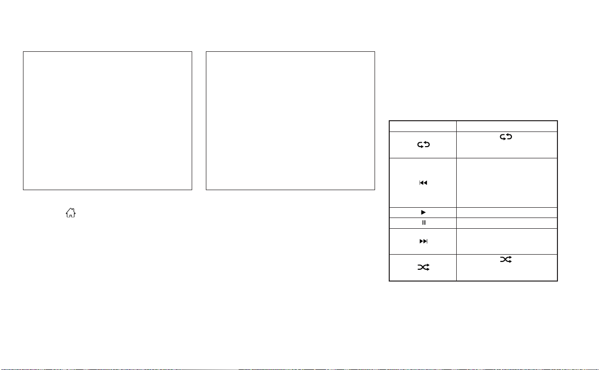
USB connections screen
Press the MENU button and touch the
“Connections” key or press the “Settings”
key and touch the “Connections” key to
change USB settings.
• Auto Change Source
Touch “ON” or “OFF” to change the audio
source settings for USB memory devices
or an iPod® connected through a USB
cable.
USB screen
1. “USB Menu” key
Touch to switch to the USB Menu screen.
2. Track information
Track information such as the song
name, artist name and album name are
displayed.
3. Audio source indicator
Indicates the currently selected audio
source.
4. USB operation keys
Touch to control USB playback
functions
5. Play time and progress bar
The play time of the track is displayed.
The bar indicates the progress in playing
a track.
USB operation keys
Touch to control USB playback functions.
Keys Description
Each time “ ”keyis
touched, the repeat mode
changes.
Touch to return to the begin-
ning of the current track.
Touch again to select the
previous track. Touch and
hold to rewind the current
track.
Touch to play the track.
Touch to pause the track.
Touch to select the next
track. Touch and hold to
fast-forward the track.
Each time “ ”keyis
touched, the random mode
changes.
LHA4711 LHA4710
4-54 Monitor, climate, audio, phone and voice recognition systems

USB memory device player
operation
Activation and playing
Connecting the USB memory device into
the port will start playing the USB memory.
USB memory device can also be played by
touching the “USB” key on the Menu screen
or by touching USB on the Launch Bar.
To pause playing the USB memory device
touch the “
” key. To resume playing,
touch the “
”key.
Skipping tracks
To skip the tracks, press the or
buttons on the control panel or touch the “
”or“ ” keys on the screen repeat-
edly until the preferred track is selected.
NOTE:
Depending on the condition, skipping to
the previous track may require pressing
the button or touching the key twice.
Pressing the button or touching the key
once may only restart the current track
from the beginning.
Fast-forwarding/rewinding
To rewind or fast-forward the track, press
and hold the
or buttons on the
control panel or touch and hold the “
”
or “
” keys on the screen.
Changing play mode
Repeat mode
Touch the “
” key on the USB screen to
change the repeat mode.
The following modes are available:
All: Repeat all
1 Folder: Repeat folder/sub-folder
1 Track: Repeat track
Random mode
Touch the “
” key on the screen to
change the random mode as follows:
No text displayed: Random off
All: Repeat all
1 Folder: Repeat folder/sub-folder
USB menu
Touch the “USB Menu” key on the USB
screen to display the USB Menu screen.
“Now Playing” key Touch to display the USB
screen.
“Folder List” key Touch to display the folder list.
Touch an item on the list to
select the folder. The sub-
folder or track list will be dis-
played. Select a sub-folder or
track from the list.
“Album Artwork” Touch to run on/off the album
artwork display on the USB
screen.
Monitor, climate, audio, phone and voice recognition systems 4-55

iPod®* PLAYER OPERATION
Connecting iPod®
WARNING
Do not connec t, disconnect, or operate
the USB device while driving. Doing so
can be a distraction. If distracted you
could lose control of your vehicle and
cause an accident or serious injury.
CAUTION
• Do not force the USB device into the
USB port. Inserting the USB device
tilted or up-side-down into the port
may damage the port. Make sure
that the USB device is connected cor-
rectly into the USB port.
• Do not grab the USB port cover (if so
equipped) when pulling the USB de-
vice out of the port. This could dam-
age the port and the cover.
• Do not leave the USB cable in a place
where it can be pulled unintention-
ally. Pulling the cable may damage
the port.
For additional information, refer to your de-
vice manufacturer’s owner information re-
garding the proper use and care of the
device.
To connect an iPod® to the vehicle so that
the iPod® can be controlled with the audio
system controls and display screen, use
the USB connection port located beneath
the heater and air conditioner controls.
Connect the iPod®-specific end of the
cable to the iPod® and the USB end of the
cable to the USB connection por t on the
vehicle. If your iPod® supports charging via
a USB connection, its battery will be
charged while connected to the vehicle
with the ignition switch in the ON position.
While connected to the vehicle, the iPod®
can only be operated by the vehicle audio
controls.
To disconnect the iPod® from the vehicle,
remove the USB end of the cable from the
USB connection port on the vehicle, then
remove the cable from the iPod®.
* iPod® is a trademark of Apple Inc., regis-
tered in the U.S. and other countries.
Compatibility
The following models are compatible:
• iPod® Classic 5th generation (firmware
version 1.3.0 or later)
• iPod® Classic 6th generation (firmware
version 2.0.1 or later)
• iPod® Classic 7th generation (firmware
version 2.0.4 or later)
• iPod® Touch 2nd generation (firmware
version 4.2.1 or later)*
• iPod® Touch 3rd generation (firmware
version 5.1 or later)
• iPod® Touch 4th generation (firmware
version 5.1 or later)
• iPod® nano - 1st generation (firmware
version 1.3.1 or later)
LHA4964
4-56 Monitor, climate, audio, phone and voice recognition systems

• iPod® nano - 2nd generation (firmware
version 1.1.3 or later)
• iPod® nano - 3rd generation (firmware
version 1.1.3 or later)
• iPod® nano - 4th generation (firmware
version 1.0.4 or later)
• iPod® nano - 5th generation (firmware
version 1.0.2 or later)
• iPod® nano - 6th generation (firmware
version 1.1 or later)
• iPhone® 3G (firmware version 4.2.1 or later)
• iPhone® 3GS (firmware version 5.1 or later)
• iPhone® 4 (firmware version 5.1 or later)
• iPhone® 4S (firmware version 5.1 or later)
* Some features of this iPod® may not be
fully functional.
Make sure that your iPod® firmware is up-
dated to the version indicated above.
iPod screen
1. “iPod Menu” key
Touch to switch to the iPod Menu screen.
2. Track information
Track information such as the song
name, artist name and album name are
displayed.
3. Audio source indicator
Indicates the currently selected audio
source.
4. Album artwork
An image of the album artwork is dis-
played when available if the setting is
turned on.
5. iPod® operation keys
Touch to control iPod® playback
functions
6. Play time and progress bar
The play time of the track is displayed.
The bar indicates the progress in playing
a track.
iPod® operation keys
Touch to control iPod® playback functions.
Keys Description
Each time “ ” key is touched,
the repeat mode changes.
Touch to return to the beginning of
the current track. Touch again to se-
lect the previous track. Touch and
hold to rewind the current track.
Touch to play the track.
Touch to pause the track.
Touch to select the next track. Touch
and hold to fast-forward the track.
Each time “ ” key is touched,
the random mode changes.
LHA4724
Monitor, climate, audio, phone and voice recognition systems 4-57

iPod® memory device player
operation
Activation and playing
Connecting the iPod® to the vehicle via USB
cable will activate the iPod® mode.
The iPod® can also be played by touching
the “iPod” key on the Menu screen or by
touching iPod on the Launch Bar.
Skipping tracks
To skip the tracks, press the or
buttons on the control panel or touch the “
”or“ ” keys on the screen repeat-
edly until the preferred track is selected.
NOTE:
Depending on the condition, skipping to
the previous track may require pressing
the button or touching the key twice.
Pressing the button or touching the key
once may only restart the current track
from the beginning.
Fast-forwarding/rewinding
To rewind or fast-forward the track, press
and hold the
or buttons on the
control panel or touch and hold the “
”
or “
” keys on the screen,
Changing play mode
Repeat mode
Touch the “
” key on the iPod® screen
to change the repeat mode. The following
modes are available.
No text displayed: Repeat off
All: Repeat all
One: Repeat track
Random mode
Touch the “
” key on the screen to
change the random mode as follows.
“
” is not highlighted: Random off
“
” highlighted: Random on
iPod® Menu
Touch the “iPod Menu” key on the iPod®
screen to display the iPod® Menu screen.
“Now Playing” key Touch to display the USB
screen.
“Folder List” key (if
so equipped)
Touch to display the folder list.
Touch an item on the list to
select the folder. The sub-
folder or track list will be dis-
played. Select a sub-folder or
track from the list.
“Album Artwork”
key
Touch to run on/off the album
artwork display on the USB
screen.
“Playlists” key Touch to display the list ac-
cording to the selected item.
“Artists” key
“Albums” key
“Songs” key
“Podcasts” key
“Genres” key
“Composers” key
“Audiobooks” key
“iTunes Radio”
key
4-58 Monitor, climate, audio, phone and voice recognition systems

BLUETOOTH® STREAMING AUDIO
If you have a compatible Bluetooth® audio
device that is capable of playing audio files,
the device can be connected to the vehi-
cle's audio system so that the audio files on
the device play through the vehicle's
speakers. For additional information, see
“FM/AM radio” (P. 4-48).
NOTE:
For additional information, refer to the
cellular phone owner’s manual.
Connecting procedure
NOTE:
The connecting procedure must be per-
formed when the vehicle is stationary. If
the vehicle starts moving during the pro-
cedure, the procedure will be canceled.
To connect a phone to the Bluetooth®
Hands-Free Phone System:
Manual Connecting Procedure
1. Press the
MENU button on the con-
trol panel.
2. Touch the “Connections” key on the
screen.
3. In the Bluetooth tab, touch the “Add New”
key to connect a phone.
4. When a compatible phone is found a
message with a PIN appears on the
screen.
5. Verify the PIN is correct and accept the
connection.
Menu Item Result
Bluetooth Allows user to switch Bluetooth® on and off. Bluetooth® must be turned on in order to connect a device.
ON Turns Bluetooth® functionality on. To turn off, touch the “ON” key again. The indicator light will go off.
Favorite (Connection first) Allows user to toggle “Phone” and “Audio” favorite settings on and off.
PIN Allows user to customize the PIN to a four digit number.
LHA4726
Monitor, climate, audio, phone and voice recognition systems 4-59

Automatic Connecting Procedure
If no phone is connected to the system,
press and hold the
button on the
steering wheel for less than 1.5 seconds.
After the prompt, speak “Add Phone”, the
system will announce “transferring to the
add phone settings menu”. The system will
start the pairing procedure. When a com-
patible phone is found, a message with a
PIN appears on the screen. Operate the
Bluetooth® phone to complete the con-
nection process. For additional informa-
tion, see “Bluetooth® connections screen”
(P. 4-80).
Bluetooth® screen
1. “BT Menu” key
Depending on the Bluetooth® version
supported by the connected device, ei-
ther the “BT Menu” key or “Connections”
key is displayed.
2. Track information
Track information such as the song
name, artist name and album name are
displayed.
3. Audio source indicator
Indicates the currently selected audio
source.
4. Bluetooth® audio operation keys
Touch to control Bluetooth® audio play-
back functions
5. Play time and progress bar
The play time of the track is displayed.
The bar indicates the progress in playing
a track.
Bluetooth® operation keys
Touch to control Bluetooth® playback
functions.
Keys Description
Each time “ ”keyis
touched, the repeat mode
changes.
Touch to return to the begin-
ning of the current track.
Touch again to select the
previous track. Touch and
hold to rewind the current
track.
Touch to play the track.
Touch to pause the track.
Touch to select the next
track. Touch and hold to
fast-forward the track.
Each time “ ”keyis
touched, the random mode
changes.
LHA4727
4-60 Monitor, climate, audio, phone and voice recognition systems

Bluetooth® audio operation
The ability to pause, change tracks, fast
forward, rewind, randomize and repeat
music may be different between devices.
Some or all of these functions may not be
supported on each device.
NOTE:
Depending on the Bluetooth® audio de-
vice that is connected, it may not be pos-
sible to perform audio operations or a
delay may occur before music is played
back.
Activation and playing
A Bluetooth® audio device can be played by
touching the “Bluetooth” key on the Menu
screen or by touching Bluetooth on the
Launch Bar.
To pause playing the Bluetooth® audio,
touch the “
” key. Touch the “ ”key
to resume playing.
Changing folders
To change folders, touch the “BT Menu” key.
Fast-forwarding/rewinding
To fast-forward or rewind the track, press
and hold the
or buttons on the
control panel or touch the “
”or“ ”
keys on the screen.
Changing play mode
Repeat mode
Touch the “
” key on the screen to
change the repeat mode.
Random mode
Touch the “
” key on the screen to
change the random mode.
NOTE:
Available repeat/random modes change
depending on the connected device.
BT Menu
Touch the “BT Menu” key on the Bluetooth®
audio screen to display the Bluetooth® au-
dio menu screen.
The following items are available.
“Now Playing” key Touch to display the
Bluetooth® audio screen.
“Current List” key (if so
equipped)*
A list of track in the cur-
rently selected folder is
displayed.
“Connections” key Touch to display the con-
nections screen.
“Folder List” key* Touch to display the
folder list. Touch an item
on the list to select the
folder.
*: displayed only when available.
NOTE:
Depending on the connected device, the
“BT Menu” key may not be displayed.
Monitor, climate, audio, phone and voice recognition systems 4-61

STEERING WHEEL SWITCH FOR
AUDIO CONTROL
1. Menu control switch/ OK
button
2.
(back) switch
3.
(SEEK/TRACK) buttons
4. Volume control switch
Volume control switch
Push the volume control switch up or down
to increase or decrease the volume.
Menu control
switch/OK button
In the vehicle information display, navigate
to “Audio”. Use the OK button to change the
mode in the following sequence:
AM → FM → USB/iPod®*→ Bluetooth® Au-
dio* → AUX* → AM.
* These modes are only available when
compatible media storage is inserted into
the device or connected to the system.
SEEK/TRACK buttons
For most audio sources, pushing the tun-
ing switches for more than 1.5 seconds
provides a different function than pushing
for less than 1.5 seconds.
AM and FM:
• Press the
or buttons for less
than 1.5 seconds to increase or decrease
the preset station.
• Press the
or buttons for more
than 1.5 seconds to seek up or down to
the next station.
iPod®:
• Press the
or buttons for less
than 1.5 seconds to increase or decrease
the track number.
USB:
• Press the
or buttons for less
than 1.5 seconds to increase or decrease
the track number.
• Press the
or buttons for more
than 1.5 seconds to reverse or fast for-
ward the current song.
Bluetooth® Audio:
• Press the
or buttons for less
than 1.5 seconds to skip ahead or back to
the next song.
• Press the
or buttons for more
than 1.5 seconds to reverse or fast for-
ward the current song.
(back) switch
Push the (back) switch to return to the
previous screen or cancel the current
selection.
LHA4122
4-62 Monitor, climate, audio, phone and voice recognition systems

There is a USB/iPod® charging port located
on the rear center console. This port will
charge compatible devices.
NOTE:
Only the USB connection port located
below the instrument panel will allow
operation of the USB/iPod® devices
through the audio system.
The antenna pattern is printed inside the
rear window.
CAUTION
• Do not place metalized film near the
rear window glass or attach any
metal parts to it. This may cause poor
reception or noise
• When cleaning the inside of the rear
window, be careful not to scratch or
damage the rear window antenna.
Lightly wipe along the antenna with a
dampened soft cloth.
Apple Siri® Eyes Free personal assistant
can be accessed from the vehicle. Siri Eyes
Free can be accessed in Siri Eyes Free
mode to reduce user distraction. In this
mode, Siri Eyes Free is available for interac-
tion by voice control. After connecting a
compatible Apple device by using
Bluetooth®, Siri Eyes Free can be activated
from the
button on the steering
wheel.
Siri® is a trademark of Apple Inc., registered
in the U.S. and other countries.
• Some Siri Eyes Free functions, such as
displaying pictures or opening apps, may
not be available while driving.
• For getting best results, always update
your device to the latest software version.
• Keep the interior of the vehicle as quiet as
possible. Close the windows to eliminate
the surrounding noises (traffic noises, vi-
bration sounds, etc.), which may prevent
the system from recognizing the voice
commands correctly.
• For functions that can be used in Siri Eyes
Free, please refer to the Apple website.
LHA4803
USB/iPod® CHARGING PORT (if so
equipped)
ANTENNA SIRI® EYES FREE (if so equipped)
Monitor, climate, audio, phone and voice recognition systems 4-63

REQUIREMENTS
Siri® is only available on the iPhone® 4S or
later. Devices released before iPhone® 4S
are not supported by the Siri® Eyes Free
system. Visit www.apple.com/ios/siri for
details about device compatibility.
Siri must be enabled on the phone. Please
check phone settings.
If the device has a lock screen, Siri must be
accessible from the lock screen. Please
check phone settings.
For best results, always update your device
to the latest software version.
OPERATING SIRI® EYES FREE
1. Press button for more than 1.5
seconds.
2. Speak your command and then listen to
the Siri® Eyes Free reply.
After starting Siri Eyes Free, press the
button again within 5 seconds of the end of
the Siri Eyes Free announcement to extend
the session.
Example 1 – Playing music
1. Press
button for more than 1.5
seconds.
2. Say “Play (artist name, song name, etc.)”.
3. Your vehicle will automatically change to
Bluetooth® Audio or iPod® mode* when
the music starts playing. Mode selection
is determined by the phone.
* If the iPhone® is also connected with the
USB cable.
If the audio track does not star t playing
automatically after Siri Eyes Free ends, try
changing the track or audio source to re-
sume playback.
NOTE:
For best results, use the native music
app. Performance of music control func-
tion while using Podcasts, Audiobook or
other 3rd party music apps may vary and
is controlled by the iPhone®.
Example2–Replying to text messages
1.
If a compatible iPhone® is connected and
“Show Notifications” of the iPhone® settings
is enabled, the vehicle will display a notifica-
tion for new incoming text messages.
2. After reading the message, press or
press and hold the
button to reply
using Siri Eyes Free.
3. After a beep sounds, say “Text message”
or a similar command to reply using Siri
Eyes Free.
LHA4965
4-64 Monitor, climate, audio, phone and voice recognition systems

TROUBLESHOOTING GUIDE
Symptom Cause and Countermeasure
Cannot access Siri Eyes
Freefromswitchonthe
steering wheel
Check if a Bluetooth® connection is established between the iPhone® and the system.
Check if Siri is enabled on the device. On your phone, go to Siri setting.
Check that Siri can be accessed from the device lock screen. This can be set in the settings menu of your phone.
Audio Source does not
change automatically to
iPod® or Bluetooth® Au-
dio mode
For best results, use the native Music app. Performance of music control function while using Podcasts, Audiobook or other 3rd party
music apps may vary.
For best results, play media already stored on your device. Streaming music or playback from cloud storage may degrade perfor-
mance.
Switch the source manually by pressing the AUX or MEDIA button on the vehicle audio system or the SOURCE select switch on the
steering wheel.
Play, pause, next track,
previous track or play
timer does not work
For best results, use the native Music app. Performance of music control function while using Podcasts, Audiobook or other 3rd party
music apps may vary and is controlled by the device.
Cannot hear any music/
audio being played back
from a connected
iPhone®
Check that the audio source is set to Bluetooth® Audio or iPod® mode. A USB connection is required for iPod® mode.
Cannot receive text mes-
sage notifications on the
vehicle audio system
Check if “Send Notifications” is enabled on your phone. On the phone, go to Bluetooth® settings. Find the device name, like “My Car”.
Press the INFO button. Turn on “Show Notifications”.
Cannot reply to text mes-
sage notifications by Siri
Eyes Free
After receiving an incoming text message, follow on-screen guidance. Press the
button for more than 1.5 seconds on the steer-
ing wheel for Siri Eyes Free. After Siri Eyes Free starts, say “Text Message”.
Monitor, climate, audio, phone and voice recognition systems 4-65

When installing a CB, ham radio or car
phone in your vehicle, be sure to observe
the following precautions; otherwise, the
new equipment may adversely affect the
engine control system and other electronic
parts.
WARNING
• A cellular phone should not be used
for any purpose while driving so full
attention may be given to vehicle op-
eration. Some jurisdictions prohibit
the use of cellular phones while
driving.
• If you must make a call while your
vehicle is in motion, the hands free
cellular phone operational mode is
highly recommended. Exercise ex-
treme caution at all times so full at-
tention may be given to vehicle
operation.
• If you are unable to devote full atten-
tion to vehicle operation while talk-
ing on the phone, pull off the road to
a safe location and stop your vehicle.
CAUTION
• Keep the antenna as far away as pos-
sible from the electronic control
modules.
• Keep the antenna wire more than 8 in
(20 cm) away from the electronic
control system harnesses. Do not
route the antenna wire next to any
harness.
• Adjust the antenna standing-wave
ratio as recommended by the
manufacturer.
• Connect the ground wire from the CB
radio chassis to the body.
• For additional information, it is rec-
ommended that you visit a NISSAN
dealer for servicing.
WARNING
• Use a phone after stopping your ve-
hicle in a safe location. If you have to
use a phone while driving, exercise
extreme caution at all times so full
attention may be given to vehicle
operation.
• If you are unable to devote full atten-
tion to vehicle operation while talk-
ing on the phone, pull off the road to
a safe location and stop your vehicle.
CAUTION
To avoid discharging the vehicle bat-
tery, use a phone after starting the
engine.
CAR PHONE OR CB RADIO BLUETOOTH® HANDS-FREE PHONE
SYSTEM
4-66 Monitor, climate, audio, phone and voice recognition systems

Your NISSAN is equipped with the
Bluetooth® Hands-Free Phone System. If
you have a compatible Bluetooth® enabled
cellular phone, you can set up the wireless
connection between your cellular phone
and the in-vehicle phone module. With
Bluetooth® wireless technology, you can
make or receive a hands-free telephone
call with your cellular phone in the vehicle.
Once your cellular phone is connected to
the in-vehicle phone module, no other
phone connecting procedure is required.
Your phone is automatically connected
with the in-vehicle phone module when
the ignition switch is placed in the ACC or
ON position with the previously connected
cellular phone turned on and carried in the
vehicle.
NOTE:
Some devices require the user to accept
connections to other Bluetooth® de-
vices. If your phone does not connect au-
tomatically to the system, consult the
phone's owner's manual for details on
device operation.
You can connect up to six different
Bluetooth® cellular phones to the in-
vehicle phone module. However, you can
talk on only one cellular phone at a time.
Before using the Bluetooth® Hands-Free
Phone System, refer to the following notes.
• Set up the wireless connection between
a compatible cellular phone and the in-
vehicle phone module before using the
hands-free phone system.
• Some Bluetooth® enabled cellular
phones may not be recognized or work
properly. Please visit
www.nissanusa.com/bluetooth or
www.nissan.ca/bluetooth for a recom-
mended phone list and connecting
instructions.
LHA4953
Monitor, climate, audio, phone and voice recognition systems 4-67

• You will not be able to use a hands-free
phone under the following conditions:
– Your vehicle is outside of the cellular
service area.
– Your vehicle is in an area where it is
difficult to receive a cellular signal; such
as in a tunnel, in an underground park-
ing garage, near a tall building or in a
mountainous area.
– Your cellular phone is locked to prevent
it from being dialed.
• When the radio wave condition is not
ideal or ambient sound is too loud, it may
be difficult to hear the other person's
voice during a call.
• Do not place the cellular phone in an area
surrounded by metal or far away from
the in-vehicle phone module to prevent
tone quality degradation and wireless
connection disruption.
• While a cellular phone is connected
through the Bluetooth® wireless connec-
tion, the battery power of the cellular
phone may discharge quicker than usual.
The Bluetooth® Hands-Free Phone Sys-
tem cannot charge cellular phones.
• Some cellular phones or other devices
may cause interference or a buzzing
noise to come from the audio system
speakers. Storing the device in a different
location may reduce or eliminate the
noise.
• For additional information, refer to the
cellular phone owner's manual regarding
the telephone charges, cellular phone
antenna and body, etc.
REGULATORY INFORMATION
FCC Regulatory information
– CAUTION: To maintain compliance with
FCC’s RF exposure guidelines, use only
the supplied antenna. Unauthorized an-
tenna, modification, or attachments
could damage the transmitter and may
violate FCC regulations.
– Operation is subject to the following two
conditions:
1.1) This device may not cause interfer-
ence and
2.2) this device must accept any interfer-
ence, including interference that may
cause undesired operation of the
device.
IC Regulatory information
– Operation is subject to the following two
conditions: (1) this device may not cause
interference, and (2) this device must ac-
cept any interference, including interfer-
ence that may cause undesired opera-
tion of the device.
– This Class B digital apparatus meets all
requirements of the Canadian
Interference-Causing Equipment
Regulations.
BLUETOOTH® is a
trademark owned by
Bluetooth SIG, Inc. and
licensed to
Panasonic.
USING THE SYSTEM
The system allows hands-free operation of
the Bluetooth® Hands-Free Phone System.
If the vehicle is in motion, some commands
may not be available so full attention may
be given to vehicle operation.
4-68 Monitor, climate, audio, phone and voice recognition systems

Initialization
When the ignition switch is placed in the ON
position, NISSAN Voice Recognition is initial-
ized, which takes a few seconds. If the
button is pressed before the initialization
completes, the system will announce
“There is no phone connected” and will not
react to voice commands.
Operating tips
To get the best performance out of the
NISSAN Voice Recognition System, observe
the following:
• Keep the interior of the vehicle as quiet as
possible. Keep all vents pointed away
from the microphone and close the win-
dows to eliminate surrounding noises
(traffic noises, vibration sounds, etc.),
which may prevent the system from rec-
ognizing voice commands correctly.
• Wait until the tone sounds before speak-
ing a command. Otherwise, the com-
mand will not be received properly.
• Start speaking a command within 5 sec-
onds after the tone sounds.
• Speak in a natural voice without pausing
between words.
• For calling contacts by name, please say
both the first and last name of the con-
tact for better recognition.
Giving voice commands
To operate NISSAN Voice Recognition,
press the
button located on the steer-
ing wheel for less than 1.5 seconds. After
the tone sounds, speak a command.
The command given is picked up by the
microphone, and voice feedback is given
when the command is accepted.
• If a command is not recognized, the sys-
tem announces, “Please say or select a
command from the displayed list.” Make
sure the command is said exactly as
prompted by the system and repeat the
command in a clear voice.
• If you want to go back to the previous
command, you can say “Go back” or “Cor-
rection” any time the system is waiting for
a response.
• You can cancel a command when the
system is waiting for a response by say-
ing, “Cancel” or “Quit.” The system an-
nounces “Exit” and ends the Voice Recog-
nition session. You can also press and
hold the
button on the steering
wheel for 1.5 seconds at any time to end
the Voice Recognition session. Whenever
the Voice Recognition session is can-
celed, a double beep is played to indicate
you have exited the system.
• If you want to adjust the volume of the
voice feedback, push the (+ or -) volume
control switches on the steering wheel
while being provided with feedback. You
can also use the radio volume control
knob.
Voice Prompt Interrupt
In most cases you can interrupt the voice
feedback to speak the next command by
pressing the
button on the steering
wheel. After interrupting the system, wait
for a beep before speaking your command.
Monitor, climate, audio, phone and voice recognition systems 4-69
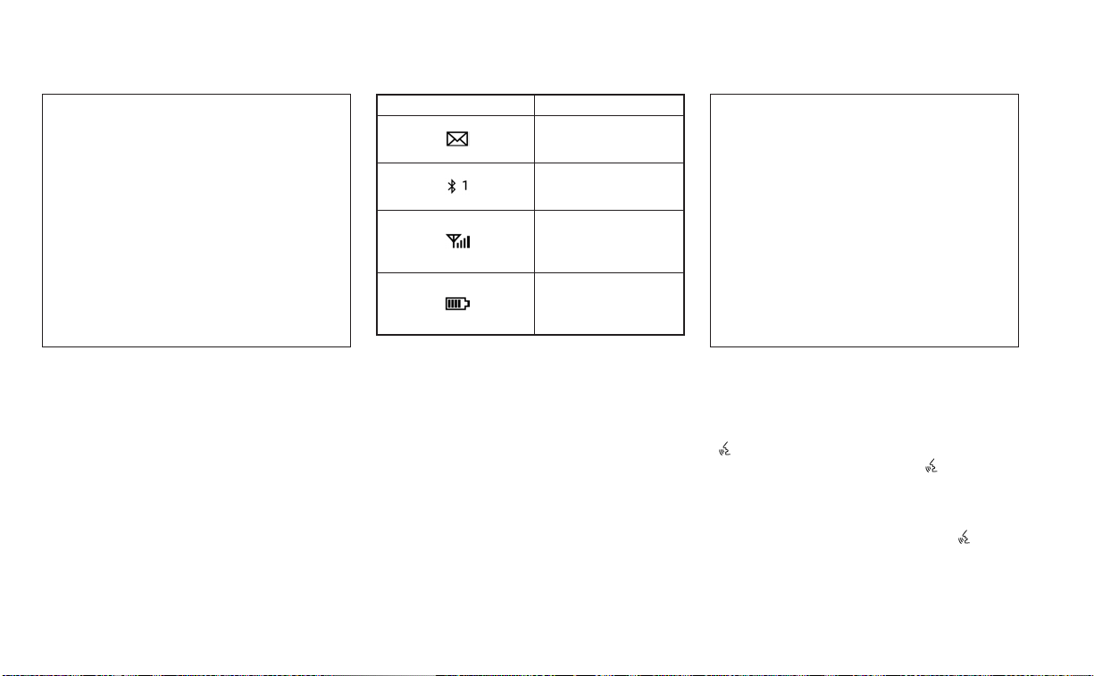
INDICATORS
When a cellular phone is connected
through the Bluetooth® wireless connec-
tion, indicators
O
1
for the phone and text
messaging are displayed on the top of the
screen.
Indicator Description
Indicates there are un-
read received mes-
sages.
Indicates the
Bluetooth® device that
is currently connected.
Indicates the strength
of the signal the
Bluetooth® device is
receiving.
Indicates the amount
of remaining
Bluetooth® device
battery.
CONTROL BUTTONS
The control buttons for the Bluetooth®
Hands-Free Phone System are located on
the steering wheel.
VOICE COMMAND BUTTON
Press and hold the
button
for more than 1.5 seconds to initi-
ate the Voice Recognition session.
To exit the Voice Recognition ses-
sion press and hold the
for
more than 1.5 seconds. For addi-
tional information, see “Voice
prompt interrupt” (P. 4-69).
LHA4723 LHA4954
4-70 Monitor, climate, audio, phone and voice recognition systems
You can use the button to
interrupt the system feedback
and give a command at once.
If an iPhone® is connected, Siri®
can be accessed by pressing the
button for less than 1.5 sec-
onds. For additional information,
see “Siri® Eyes Free” (P. 4-63).
PHONE BUTTON
To answer an incoming call or to
end a call press the
button.
To reject a call press and hold the
button.
BLUETOOTH® CONNECTING
PROCEDURE
NOTE:
The connecting procedure must be per-
formed when the vehicle is stationary. If
the vehicle starts moving during the pro-
cedure, the procedure will be canceled.
To connect a phone to the Bluetooth®
Hands-Free Phone System:
Bluetooth® Connecting Procedure
1. Select the “Settings” key on the Launch
Bar.
2. Touch the “Connections” key.
3. Touch the Bluetooth tab and touch the
“Add New” key.
4. Follow the instructions on the screen.
If a PIN appears on the screen, operate the
Bluetooth® device to enter/confirm the
PIN.
Menu Item Result
Bluetooth Allows user to switch Bluetooth® on and off. Bluetooth® must be turned on in order to connect a device.
ON Turns Bluetooth® functionality on. To turn off, touch the “ON” key again. The indicator light will go off.
Favorite (Connection first) Allows user to toggle “Phone” and “Audio” favorite settings on and off.
PIN Allows user to customize the PIN to a four digit number.
LHA4726
Monitor, climate, audio, phone and voice recognition systems 4-71

NOTE:
Some cellular phones may require you to
accept certain permissions in order to
enable features on your Bluetooth® sys-
tem. During the Bluetooth® pairing pro-
cess, please check your cellular phone’s
display for a pop-up with the request to
grant phonebook access.
Granting phonebook access permission
will allow your contacts to be down-
loaded to the vehicle’s Bluetooth® sys-
tem. A pop-up may display on your cellu-
lar phone stating that the Bluetooth®
system would like to access your con-
tacts and call history. Please select “Al-
low” or Yes” to grant this permission.
Automatic Connecting Procedure
If no phone is connected to the system,
press and hold the
button on the
steering wheel for less than 1.5 seconds.
After the prompt, speak “Add Phone”, the
system will announce “transferring to the
add phone settings menu”. The system will
start the pairing procedure. When a com-
patible phone is found, a message with a
PIN appears on the screen. Operate the
Bluetooth® phone to complete the con-
nection process. For additional informa-
tion, see “Bluetooth® connections screen”
(P. 4-80).
VOICE COMMANDS
Voice commands can be used to operate
the Bluetooth® Hands-Free Phone System.
Press and hold the
button for less
than 1.5 seconds to bring up the phone
command menu. The commands avail-
able are:
• Call <name>
• Dial <number>
• Recent Calls
• Read/Send Text (if so equipped)
• Siri® (if so equipped)
• Voice Assistant (if so equipped)
• Phonebook
• Quick Dial
• Redial
• Select Phone
• Add Phone
• Call <name> Mobile
• Call <name> Home
• Call <name> Office
• Call <name> Main
• Call <name> Other
• Settings
“Call <name>”
Speak this command to make a call to a
contact that is stored in the phonebook.
Say “Call” followed by a phonebook name to
initiate a call. If the system does not recog-
nize the name it will display a list of similar
names. After the prompt, speak or touch
an item number from the displayed list to
place the call.
“Dial <number>”
Speak this command to make a call with a
spoken phone number. After the prompt,
say “Dial” followed bya7to10digit phone
number. The system will repeat the num-
ber back. Say “Dial” to initiate the call or
“Correction” to re-enter the phone number.
4-72 Monitor, climate, audio, phone and voice recognition systems

“Recent Calls”
The following commands are available un-
der “Recent Calls”:
• Incoming Calls
Speak this command to list the last 20
incoming calls to the vehicle. If the call is
from an entry in the phonebook, the
name will be displayed. Otherwise, the
phone number of the incoming call will
be displayed.
When prompted, speak or touch the item
number on the screen to place the call.
Touch the “Next” key to move through the
list of incoming calls.
• Outgoing Calls
Speak this command to list the last 20
outgoing calls from the vehicle. If the call
was to an entry in the phonebook, the
name will be displayed. Otherwise, the
phone number of the outgoing call will be
displayed.
When prompted, speak or touch the item
number on the screen to place the call.
Touch the “Next” key to move through the
list of outgoing calls.
• Missed Calls
Speak this command to list the last 20
missed calls to the vehicle. If the call is
from an entry in the phonebook, the
name will be displayed. Otherwise, the
phone number of the missed call will be
displayed.
When prompted, speak or touch the item
number on the screen to place the call.
Touch the “Next” key to move through the
list of missed calls.
“Read Text/Send Tex t” (if so
equipped)
Speak this command to access text mes-
saging functions.
For additional information, see “Text mes-
saging” (P. 4-76).
“Phonebook through voice
command”
Speak “Phonebook” to view a list of quick
steps to access entries stored in the
phonebook. Commands are organized by
the phone number type selected in the cel-
lular device. For additional information, re-
fer to the cellular phone’s owner’s manual.
The following commands are available:
• <Say a Contact Name>
• <Say a Contact Name> Main
• <Say a Contact Name> Home
• <Say a Contact Name> Mobile
• <Say a Contact Name> Office
• <Say a Contact Name> Other
For additional information on manually se-
lecting phonebook entries, see “Making a
call” (P. 4-75).
“Quick dial”
Speak this command to access the Quick
dial menu. After the prompt, speak or se-
lect an item number on the displayed list to
place the call. For additional information,
see “Making a call” (P. 4-75).
“Redial”
Speak this command to call the last num-
ber dialed. After the prompt, say “Redial” to
dial the number of the last outgoing call.
The system will display “Redialing <name/
number>”. The name of the phonebook en-
try will be displayed if it is available, other-
wise the number being redialed will be
displayed.
Monitor, climate, audio, phone and voice recognition systems 4-73

“Select Phone”
Speak this command to access the Con-
nections menu. For additional information,
see “Bluetooth® connections screen”
(P. 4-80).
“Add Phone”
Speak this command to access the Con-
nections menu. For additional information,
see “Bluetooth® connections screen”
(P. 4-80).
“Settings”
Speak this command to access the Sys-
tem Voice settings menu. The system will
exit Voice Recognition mode. Touch one of
the following options on the screen to
change the settings.
• Beep Only for Opening Prompt
By touching the “ON” key, the indicator
light will illuminate, the system voice will
turn off and only a tone will sound when
the Bluetooth® Hands-Free Phone Sys-
tem is activated. To turn the system voice
back on, touch the “ON” key again, the
indicator light will turn off.
• Best Match List
When the system doesn't recognize a
phonebook name or dial number, it will
provide a list of similar sounding results.
To turn this off, touch the “ON” key, the
indicator light will turn off. To turn on,
touch the “ON” key again, the indicator
light will turn on.
PHONE DISPLAY SCREEN
The Phone screen can be displayed by
pressing the
button on the control
panel.
The following options are displayed:
• Quick Dial
Displays the Quick Dial screen. For addi-
tional information, see “Quick dial” (P. 4-73)
• Phonebook
Displays the Phonebook screen. For addi-
tional information, see “Making a call”
(P. 4-75).
LHA4705
4-74 Monitor, climate, audio, phone and voice recognition systems

• Call History
Displays the Call History screen. For addi-
tional information, see “Making a call”
(P. 4-75).
• Dial Number
Displays the Dial Number screen. For ad-
ditional information, see “Making a call”
(P. 4-75).
• Text Message
Displays the received message screen.
For additional information, see “Text mes-
saging” (P. 4-76).
• Connections
Displays the Connections screen. For ad-
ditional information, see “Bluetooth® con-
nections screen” (P. 4-80).
• Volume
Displays the volume adjustment screen.
For additional information, see “Volume &
beeps” (P. 4-83).
MAKING A CALL
1. Press the button on the Launch Bar.
The “Phone” screen will appear on the
display.
2. Select one of the options to make a call.
Phonebook
To access the phonebook:
1. Press the
button on the steering
wheel or touch the “
” key on the
launch bar.
2. Touch the “Phonebook” key.
3. Choose the desired entry from the dis-
played list.
Call History
1. Select a phonebook name or phone
number from the recent incoming, out-
going, or missed calls tabs.
2. Touch a phonebook name or phone
number listed to initiate the call.
Dial Number
1. Enter the phone number manually using
the keypad displayed on the screen.
2. Touch the “OK” key on the screen to initi-
ate the call.
For additional options to make a call, see
“Voice commands” (P. 4-72).
RECEIVING/ENDING A CALL
When a call is received by the phone con-
nected to the vehicle’s Bluetooth® Hands-
Free Phone System, the call information is
displayed on the control panel display.
To accept the incoming call, either:
• Press the
button on the steering
wheel, or
• Touch the “
Answer” key on the
screen.
To end or reject an incoming call, either:
• Press and hold the
button on the
steering wheel, or
• Touch the “
Decline” key on the
screen.
If the user is not able to answer the call
right away, touch the “Hold Call” key dis-
played on the screen. A message will be
played for the caller: “I’m not able to take a
call right now.” The user may then accept
the call when available or reject the call.
DURING A CALL
While a call is active the following options
will appear on the control panel display:
• Mute
Touch this key to mute or unmute the
system.
Monitor, climate, audio, phone and voice recognition systems 4-75
• Dial Number
Touch this key to dial digits during the
phone call.
• Switch to Handset
Touch the “Use Handset” key on the
screen to transfer the call to the handset
(cellular phone). To transfer the call back
from the handset to the Bluetooth®
Hands-Free Phone System, press the
button on the control panel then
select the “Transfer Hands-free” key on
the screen.
NOTE:
Some jurisdictions prohibit the use of
cellular telephones while driving.
• Switch Call
This option will only be available when a
second call is active.
If supported by the phone, the
Bluetooth® Hands-Free Phone System
allows for call waiting functionality. If a
call is received while another call is al-
ready active, a message will be displayed
on the screen. Press the
button on
the steering wheel or touch the “
Answer” key on screen to accept the in-
coming call. Touch the “
Decline” key
on the screen to reject the second call.
While a call is active, press the
button
on the steering wheel to access additional
options. Speak one of the following
commands:
• “Send Digits”
Speak this command followed by the dig-
its to enter digits during the phone call.
• “Switch call”
Speak this command to hold the second
call and switch back to the original call.
TEXT MESSAGING (if so equipped)
WARNING
• Laws in some jurisdictions may re-
strict the use of “Text-to-Speech”.
Check local regulations before using
this feature.
• Laws in some jurisdictions may re-
strict the use of some of the applica-
tions and features, such as social
networking and texting. Check local
regulations for any requirements.
• Use the text messaging feature after
stopping your vehicle in a safe loca-
tion. If you have to use the feature
while driving, exercise extreme cau-
tion at all times so full attention may
be given to vehicle operation.
• If you are unable to devote full atten-
tion to vehicle operation while using
the text messaging feature, pull off
the road to a safe location and stop
your vehicle.
NOTE:
This feature is automatically disabled if
the connected device does not support
the Message Access Profile (MAP). For
additional information, refer to the
phone’s owner’s manual for details and
instructions.
4-76 Monitor, climate, audio, phone and voice recognition systems

NOTE:
Many phones may require special per-
mission to enable text messaging. Check
the phone’s screen during Bluetooth®
pairing. For some phones, you may need
to enable ‘Notifications’ in the phone’s
Bluetooth® menu for text messages to
appear on the headunit. For additional
information, refer to your phone’s own-
er’s manual. Text message integration
requires that the phone support MAP
(Message Access Profile) for both receiv-
ing and sending text messages. Some
phones may not support all text mes-
saging features. Please refer to
www.nissanusa.com/bluetooth or
www.nissan.ca/bluetooth for compat-
ibility information, as well as your de-
vice’s owner’s manual.
The system allows for the sending and re-
ceiving of text messages through the ve-
hicle interface.
The availability of the text message func-
tion may vary depending on the cellular
phone.
When the cellular phone connected to the
vehicle receives a text message, a notifica-
tion will appear on the control panel dis-
play. To check the message, touch the
“Read” key. Touch the “Ignore” key to save
the message to be checked later.
Access text messaging through the ve-
hicles Bluetooth® Hands-Free Phone or
through the vehicles control panel.
Text messaging using Bluetooth®
Hands-Free Phone System (if so
equipped)
Sending a text message (if so equipped)
1. Press and hold the
button on the
steering wheel for less than 1.5 seconds.
2. Say “Send Text” after the tone.
3. The system will provide a list of available
commands in order to determine the
recipient of the text message. Choose
from the following:
• Phonebook
• Quick Dial
• Incoming Calls
• Outgoing Calls
• Missed Calls
• Dial
4. Once a recipient is chosen, the system
prompts for which message to send.
Nine predefined messages are avail-
able. To choose one of the predefined
messages, speak one of the following
after the tone:
• “Driving, can't text”
• “Call me”
• “On my way”
• “Running late”
• “Okay”
• “Yes”
• “No”
• “Where are you?”
• “When?”
Reading a received text message
1. Press and hold the
button on the
steering wheel for less than 1.5 seconds.
2. Say “Read Text” after the tone.
The display will show a list of 20 messages
with the sender and deliver y time. Touch
the “Next” key on the screen to view all mes-
sages. To view a text message press the
button on the steering wheel and
speak the number item list on the screen.
The following options will be available:
Monitor, climate, audio, phone and voice recognition systems 4-77

• Play
Speak this command to have the system
say the message.
• Reply
Speak this command to send a text mes-
sage response to the sender of the text
message.
• Call
Speak this command to call the sender.
• Previous
Speak this command to move to the pre-
vious text message (if available).
•Next
Speak this command to move to the next
text message (if available).
Siri® Eyes Free (if so equipped)
If a connected phone is equipped with Siri®,
it can also be used to create custom mes-
sages that are sent through the phone. For
additional information, see “Siri® Eyes Free”
(P. 4-63).
NOTE:
Text messages are only displayed if the
vehicle speed is less than 5 mph (8
km/h).
NOTE:
For Apple iPhones®, text messages can
only be sent through Siri.
Text messaging using the control
panel
Display received message list
1. Press the
button on the control
panel.
2. Touch the “Text Message” key on the
screen
3. Touch an item on the list to read or reply
to the message.
Up to 100 messages can be stored in the
message list.
Received message screen
Touching the “Read” key on the incoming
message notification screen or selecting a
message from the message list will show
the details of the received message on the
display.
Available actions:
•Prev.
Touch this key to read the previous
message.
•Next
Touch this key to read the next message.
• Play/Stop
Touch the “Play” key to have the hands-
free phone system read out the received
message. Touch the “Stop” key to stop
reading.
• Call
If the sender of the message is registered
in the phonebook, touch the “Call” key to
make a call to the sender.
• Reply
A reply message can be selected from
the predefined list.
Sending a text message (if so equipped)
This function may not be supported de-
pending on the cellular phone.
1. Press the
button on the control
panel.
2. Touch the “Text Message” key on the
screen.
3. Touch the “Create Message” key on the
screen.
4-78 Monitor, climate, audio, phone and voice recognition systems

The following items are available:
Available item Action
To Enter Number by Keypad Enter the phone number of the recipient using the keypad. Touch the “OK” key to confirm.
Quick Dial Select a recipient from the quick dial list.
Phonebook Select a recipient from the phonebook.
Call History Select a recipient/phone number from call history.
Select Text Touch to display a list of predefined text messages.
Send Touch to send the message.
Monitor, climate, audio, phone and voice recognition systems 4-79

BLUETOOTH® CONNECTIONS
SCREEN
1. “ ” (back) key
2. Bluetooth tab
3. Connections screen
4. “Add New” key
5. “
” (settings) key
6. “
” (info) key
7. “
” (Bluetooth® Audio connection) key
8. “
” (Bluetooth® Hands-Free Phone
System connection) key
Access the Connections screen to change
settings and view Bluetooth® information.
To access the Connections screen press
the
MENU button on the control panel.
Touch the “Connections” key on the screen
then select the Bluetooth tab.
The paired phone will be added to the list
on the Bluetooth® connections screen.
Touching the name of another device on
the list will switch the connected device.
“ ” (back) key
Touch the “ ” key to go back to the
previous screen.
Connecting Bluetooth®
For additional information on connecting a
cellular phone or device to the Bluetooth®
Hands-Free Phone System, see
“Bluetooth® connecting procedure” (P. 4-71).
NOTE:
Some cellular phones or other devices
may cause interference or a buzzing
noise to come from the audio system
speakers. Storing the device in a differ-
ent location may reduce or eliminate the
noise.
Bluetooth tab
This tab will display up to six Bluetooth®
devices. If six devices are already con-
nected, one of the devices must be deleted
before another device can be connected.
“Add New” key
Touch the key on the screen to connect a
new Bluetooth® device. For additional in-
formation, see “Bluetooth® connecting
procedure” (P. 4-71).
“ ” (Bluetooth® settings) key
Touch the “
” key on the screen to
display a list of options.
• Bluetooth
Touch this key to turn the Bluetooth®
connection on or off
• Favorite (Connection first)
Touch this key to change which device
will be connected first when multiple de-
vices are connected to the vehicle.
Turn the “
” key on or off to make the
device a favorite connection.
Turn the “
” key on or off to make the
device a favorite connection.
LHA4716
4-80 Monitor, climate, audio, phone and voice recognition systems

• Pin
Touch this key to customize the PIN code.
Input a four digit number then touch the
“OK” key. The new PIN will be set.
“ ” (info) key
Touch the “ ” key on the screen to
display the information of the cellular
phone or to delete the device.
Touch the “Delete” key to remove a paired
device then select “Yes” when a message
appears.
“ ” (Bluetooth® Hands-Free
Phone System connection) key
A list of connected devices will be displayed
on the screen. Touch the “
” key next to
the name to connect a device to the
Hands-Free Phone System. If the phone is
listed as a favorite, a star will appear on the
icon. Touch the key again to disconnect the
device. The device will not be removed
from the list. For additional information on
removing a device, see “
(info) key”
(P. 4-81).
“ ” (Bluetooth® Audio
connection) key
A list of connected devices will be displayed
on the screen. Touch the “
” key next to
the name to connect a device to
Bluetooth® Audio. If the device is listed as a
favorite, a star will appear on the icon.
Touch the key again to disconnect the de-
vice. The device will not be removed from
the list. For additional information on re-
moving a device, see “
(info) key”
(P. 4-81).
PHONE AND TEXT MESSAGE
SETTINGS
Bluetooth® Hands-Free Phone System set-
tings can be changed according to the us-
er’s preference. To access the “Phone” set-
tings menu press the
MENU button on
the control panel. Touch the “Settings” key
then select the “Phone” key.
LHA4721
Monitor, climate, audio, phone and voice recognition systems 4-81

The following options are available:
Menu Item Result
Quick Dial Edit Entries in the Quick Dial can be edited. For additional information, see “Quick dial” (P. 4-73).
Delete All Deletes all of the stored phone numbers in quick dial.
Phonebook Download Entire Phone-
book
All the phone numbers that are stored in a phonebook in the cellular phone that is connected to the vehicle are
downloaded at once. For additional information, refer to the cellular phone’s owner’s manual.
Auto Downloaded Turns on/off automatic downloading of the phonebook when a new phone is connected.
Text Message Text Message Turns the text messaging function on/off.
Text Message Ringtone Turn the incoming message sound on/off.
Signature Turns the signature setting for the outgoing text message on/off.
Auto Reply Turns the automatic text message reply function on/off.
Auto Reply Text Message Select the text message to be used for the automatic reply. Choose from a list of predefined messages.
Notifications Driver Only When this item is turned on, incoming call notification is displayed only on the handset.
Vehicle Ringtone Turns the vehicle ringtone on/off.
Automatic Hold When this item turns on, an incoming call will be put on hold automatically.
4-82 Monitor, climate, audio, phone and voice recognition systems

VOLUME & BEEPS
There are several methods to customize
the volume settings.
Volume & Beeps
The Volume & Beeps screen can be found
by pressing the
MENU button on the
control panel, touching the “Settings” key
on the screen and selecting “Volume &
Beeps”. To adjust the volume of the follow-
ing options, touch the “–” and “+” keys on the
screen.
The available settings are:
• Ringtone
Adjust the volume level of the ringtone of
incoming calls.
• Outgoing Call
Adjust the volume level of the outgoing
calls.
• Voice Prompt Vol.
Adjust the volume level of the system
voice.
• Text-to-speech Vol.
Adjust the volume of the replay voice for
text messaging.
• Button Beeps
Turns on/off the button beep sounds and
alarm for prohibited operations.
Volume Settings
The Volume settings screen can be found
by pressing the
button on the control
panel then touching the “Volume” key on
the screen. To adjust the volume of the
following options, touch the “–” and “+” keys
on the screen.
The available settings are:
• Ringtone
Adjust the volume level of the ringtone of
incoming calls.
• Outgoing Call
Adjust the volume level of the outgoing
calls.
“Made for iPod”, “Made for iPhone” and
“Made for iPad” mean that an electronic
accessory has been designed to connect
specifically to iPod, iPhone or iPad, respec-
tively, and has been certified by the devel-
oper to meet Apple performance stan-
dards. Apple is not responsible for the
operation of this device or its compliance
with safety and regulatory standards.
Please note that the use of this accessory
with iPod, iPhone or iPad may affect wire-
less performance.
iPad, iPhone, iPod classic, iPod nano, iPod
shuffle and iPod touch are trademarks of
Apple Inc., registered in the U.S. and other
countries. Lightning is a trademark of
Apple Inc.
iPod®/IPHONE®
Monitor, climate, audio, phone and voice recognition systems 4-83

MEMO
4-84 Monitor, climate, audio, phone and voice recognition systems

5 Starting and driving
Precautions when starting and driving ..........5-4
Exhaust gas (carbon monoxide) ..............5-4
Three-way catalyst ...........................5-4
Tire Pressure Monitoring System
(TPMS) .......................................5-5
Avoiding collision and rollover ................5-9
Off-roadrecovery ............................5-9
Rapid air pressure loss .......................5-9
Drinking alcohol/drugs and driving ..........5-10
Driving safety precautions ...................5-10
Push-button ignition switch ....................5-13
Operating range ............................5-14
Push-button ignition switch positions .......5-14
Emergency engine shut off ..................5-15
NISSAN Intelligent Key® battery
discharge ...................................5-15
NISSAN Vehicle Immobilizer System .........5-16
Before starting the engine .....................5-16
Starting the engine .............................5-16
Remote Engine Start ........................ 5-17
Driving the vehicle ..............................5-18
Continuously Variable Transmission
(CVT) ........................................5-18
Parking brake ..................................5-24
Manual parking brake (pedal type) ...........5-25
Electronic parking brake (switch type) .......5-25
Automatic brake hold (if so equipped) ..........5-27
How to activate/deactivate the
automatic brake hold function ..............5-28
How to use the automatic brake hold
function .....................................5-29
Traffic Sign Recognition (TSR) (if so equipped) . . . 5-30
System operation ...........................5-31
Turning the Traffic Sign Recognition
(TSR) system on and off .....................5-32
System temporarily unavailable .............5-32
System malfunction .........................5-32
System maintenance .......................5-32
Lane Departure Warning (LDW) .................5-33
LDW system operation ......................5-34
How to enable/disable the LDW system .....5-36
LDW system limitations .....................5-38
System temporarily unavailable .............5-39
System malfunction .........................5-39
System maintenance .......................5-39
Intelligent
Lane Intervention (I-LI)
(if so equipped) .................................5-40
I-LI system operation ........................5-41
How to enable/disable the I-LI system ......5-42
I-LI system limitations .......................5-43
System temporarily unavailable .............5-44
System malfunction .........................5-45

System maintenance .......................5-45
Blind Spot Warning (BSW) (if so equipped) .......5-46
BSW system operation ......................5-48
How to enable/disable the BSW system .....5-49
BSW system limitations .....................5-51
BSW driving situations .......................5-52
System temporarily unavailable .............5-55
System maintenance .......................5-57
Rear Cross Traffic Alert (RCTA) (if so equipped) . .5-58
RCTA system operation .....................5-58
How to enable/disable the RCTA
system ......................................5-61
RCTA system limitations.....................5-63
System temporarily unavailable .............5-65
System maintenance .......................5-67
Cruise control (if so equipped) ..................5-68
Precautions on cruise control ...............5-68
Cruise control operations ...................5-69
ProPILOT Assist (if so equipped) ................5-70
ProPILOT Assist system operation ...........5-72
Turning the conventional (fixed speed)
cruise control mode on .....................5-75
Operating ProPILOT Assist ...................5-76
How to enable/disable the Steering
Assist .......................................5-81
Intelligent Cruise Control (ICC)
(for vehicles with ProPILOT Assist) ...........5-82
Steering Assist ..............................5-94
Conventional (fixed speed) cruise
control mode ..............................5-100
Rear Automatic Braking (RAB)
(if so equipped) ................................5-104
RAB system operation......................5-105
Turning the RAB system on/off .............5-107
RAB system limitations .....................5-108
System malfunction ........................5-110
System maintenance ......................5-110
Automatic Emergency Braking (AEB) with
Pedestrian Detection ...........................5-111
AEB with Pedestrian Detection system
operation .................................. 5-112
Turning the AEB with Pedestrian
Detection system ON/OFF .................5-114
AEB
with Pedestrian Detection system
limitations .................................5-116
System temporarily unavailable ............5-119
System malfunction ........................5-121
System maintenance ......................5-122
Intelligent Forward Collision Warning (I-FCW) . . 5-123
I-FCW system operation ....................5-126

Turning the I-FCW system on/off ...........5-127
I-FCW system limitations ...................5-129
System temporarily unavailable ............5-134
System malfunction ........................5-136
System maintenance ......................5-137
Intelligent Driver Alertness (I-DA) ...............5-138
Intelligent Driver Alertness system
operation ..................................5-138
How to enable/disable the Intelligent
Driver Alertness (I-DA) system ..............5-139
Intelligent Driver Alertness (I-DA)
system limitations .........................5-141
Break-in schedule .............................5-142
Fuel efficient driving tips .......................5-142
Increasing fuel economy ......................5-143
All-Wheel Drive (AWD) (if so equipped) ..........5-143
Parking/parking on hills .......................5-146
Power steering ................................5-147
Brake system .................................5-148
Brake precautions ..........................5-148
Anti-lock Braking System (ABS) .............5-148
Brake Assist ................................5-150
Vehicle Dynamic Control (VDC) system ........5-150
Brake force distribution ....................5-152
Chassis Control (if so equipped) ...............5-153
Intelligent Trace Control (I-TC) ..............5-153
Active Ride Control (ARC) ...................5-153
Hill start assist system ........................5-153
Rear Sonar System (RSS) (if so equipped) ......5-154
System operation ..........................5-155
How to enable/disable the sonar
system .....................................5-157
Sonar limitations ...........................5-159
System temporarily unavailable ............5-159
System maintenance ......................5-159
Cold weather driving ..........................5-160
Freeing a frozen door lock ..................5-160
Antifreeze ..................................
5-160
B
attery.....................................5-160
Draining of coolant water ..................5-160
Tire equipment .............................5-160
Special winter equipment ..................5-161
Driving on snow or ice ......................5-161
Engine block heater (if so equipped) ........5-161
Active noise cancellation/Active sound
enhancement (if so equipped) .................5-162
Active noise cancellation ...................5-162
Active sound enhancement ................5-162
WARNING
• Do not leave children or adults who
would normally require the assis-
tance of others alone in your vehicle.
Pets should also not be left alone.
They could accidentally injure them-
selves or others through inadvertent
operation of the vehicle. Also, on hot,
sunny days, temperatures in a closed
vehicle could quickly become high
enough to cause severe or possibly
fatal injuries to people or animals.
• Closely supervise children when they
are around cars to prevent them
from playing and becoming locked in
the trunk where they could be seri-
ously injured. Keep the car locked,
with the rear seatback and trunk lid
securely latched when not in use, and
prevent children's access to car keys.
EXHAUST GAS (carbon monoxide)
WARNING
• Do not breathe exhaust gases; they
contain colorless and odorless car-
bon monoxide. Carbon monoxide is
dangerous. It can cause uncon-
sciousness or death.
• If you suspect that exhaust fumes
are entering the vehicle, drive with all
windows fully open, and have the ve-
hicle inspected immediately.
• Do not run the engine in closed
spaces such as a garage.
• Do not park the vehicle with the en-
gine running for any extended length
of time.
• Keep the rear vent windows, lift-
gates, doors and trunk lids (if so
equipped) closed while driving, oth-
erwise exhaust gases could be
drawn into the passenger compart-
ment. If you must drive with one of
these open, follow these precau-
tions:
1. Open all the windows.
2. Set the
air recirculation but-
ton to off and the fan control dial
to high to circulate the air.
• If electrical wiring or other cable con-
nections must pass to a trailer
through the seal on the trunk lid or
the body, follow the manufacturer's
recommendation to prevent carbon
monoxide entry into the vehicle.
• The exhaust system and body should
be inspected by a qualified mechanic
whenever:
a. The vehicle is raised for service.
b. You suspect that exhaust fumes
are entering into the passenger
compartment.
c. You notice a change in the sound
of the exhaust system.
d. You have had an accident involv-
ing damage to the exhaust sys-
tem, underbody, or rear of the
vehicle.
THREE-WAY CATALYST
The three-way catalyst is an emission con-
trol device installed in the exhaust system.
Exhaust gases in the three-way catalyst
are burned at high temperatures to help
reduce pollutants.
WARNING
• The exhaust gas and the exhaust
system are very hot. Keep people,
animals or flammable materials
away from the exhaust system
components.
PRECAUTIONS WHEN STARTING AND
DRIVING
5-4 Starting and driving

• Do not stop or park the vehicle over
flammable materials such as dry
grass, waste paper or rags. They may
ignite and cause a fire.
CAUTION
• Do not use leaded gasoline. Deposits
from leaded gasoline will seriously
reduce the three-way catalyst's abil-
ity to help reduce exhaust pollutants.
•
Keep your engine tuned up. Malfunc-
tions in the ignition, fuel injection, or
electrical systems can cause overrich
fuel flow into the three-way catalyst,
causing it to overheat. Do not keep
driving if the engine misfires, or if no-
ticeable loss of performance or other
unusual operating conditions are de-
tected. Have the vehicle inspected
promptly. It is recommended that you
visit a NISSAN dealer for this service.
• Avoid driving with an extremely low
fuel level. Running out of fuel could
cause the engine to misfire, damag-
ing the three-way catalyst.
• Do not race the engine while warm-
ing it up.
• Do not push or tow your vehicle to
start the engine.
TIRE PRESSURE MONITORING
SYSTEM (TPMS)
Each tire, including the spare (if provided),
should be checked monthly when cold and
inflated to the inflation pressure recom-
mended by the vehicle manufacturer on
the vehicle placard or tire inflation pressure
label. (If your vehicle has tires of a different
size than the size indicated on the vehicle
placard or tire inflation pressure label, you
should determine the proper tire inflation
pressure for those tires.)
As an added safety feature, your vehicle
has been equipped with a Tire Pressure
Monitoring System (TPMS) that illuminates
a low tire pressure telltale when one or
more of your tires is significantly under-
inflated. Accordingly, when the low tire
pressure telltale illuminates, you should
stop and check your tires as soon as pos-
sible, and inflate them to the proper pres-
sure. Driving on a significantly under-
inflated tire causes the tire to overheat and
can lead to tire failure. Under-inflation also
reduces fuel efficiency and tire tread life,
and may affect the vehicle’s handling and
stopping ability.
Please note that the TPMS is not a substi-
tute for proper tire maintenance, and it is
the driver’s responsibility to maintain cor-
rect tire pressure, even if under-inflation
has not reached the level to trigger illumi-
nation of the TPMS low tire pressure telltale.
Your vehicle has also been equipped with a
TPMS malfunction indicator to indicate
when the system is not operating properly.
The TPMS malfunction indicator is combined
with the low tire pressure telltale. When the
system detects a malfunction, the telltale will
flash for approximately one minute and then
remain continuously illuminated. This se-
quence will continue upon subsequent ve-
hicle start-ups as long as the malfunction
exists. When the malfunction indicator is illu-
minated, the system may not be able to de-
tect or signal low tire pressure as intended.
TPMS malfunctions may occur for a variety
of reasons, including the installation of re-
placement or alternate tires or wheels on
the vehicle that prevent the TPMS from func-
tioning properly. Always check the TPMS
malfunction telltale after replacing one or
more tires or wheels on your vehicle to en-
sure that the replacement or alternate tires
and wheels allow the TPMS to continue to
function properly.
Starting and driving 5-5

Additional information:
• When using a wheel without the TPMS
such as the spare tire, the TPMS does not
monitor the tire pressure of the spare tire.
• The TPMS will activate only when the ve-
hicle is driven at speeds above 16 mph (25
km/h). Also, this system may not detect a
sudden drop in tire pressure (for example,
a flat tire while driving).
• The low tire pressure warning light does
not automatically turn off when the tire
pressure is adjusted on all four tires. After
all four tires are inflated to the recom-
mended pressure, the vehicle must be
driven at speeds above 16 mph (25 km/h)
to activate the TPMS and turn off the low
tire pressure warning light. Use a tire
pressure gauge to check the tire
pressure.
• The “Tire Pressure Low - Add Air” warning
appears in the vehicle information dis-
play when the low tire pressure warning
light is illuminated and low tire pressure is
detected. The “Tire Pressure Low - Add
Air” warning turns off when the low tire
pressure warning light turns off.
• The “Tire Pressure Low - Add Air” warning
appears each time the ignition switch is
placed in the ON position as long as the
low tire pressure warning light remains
illuminated.
• The “Tire Pressure Low - Add Air” warning
does not appear if the low tire pressure
warning light illuminates to indicate a
TPMS malfunction.
• Tire pressure rises and falls depending on
the heat caused by the vehicle’s opera-
tion and the outside temperature. Do not
reduce the tire pressure after driving be-
cause the tire pressure rises after driving.
Low outside temperature can lower the
temperature of the air inside the tire
which can cause a lower tire inflation
pressure. This may cause the low tire
pressure warning light to illuminate. If the
warning light illuminates, check the tire
pressure for all four tires.
• The Tire and Loading Information label is
located in the driver's door opening.
• You can also check the tire pressure of all
tires (except the spare) on the vehicle in-
formation display screen. The order of
the tire pressure figures displayed on the
screen corresponds with the actual order
of the tire position.
For additional information, see “Low tire
pressure warning light” (P. 2-13), “Tire Pres-
sure Monitoring System (TPMS)” (P. 6-3) and
“Tire pressure” (P. 8-29).
WARNING
• Radio waves could adversely affect
electric medical equipment. Those
who use a pacemaker should contact
the electric medical equipment
manufacturer for the possible influ-
ences before use.
5-6 Starting and driving

• If the low tire pressure warning light
illuminates while driving, avoid sud-
den steering maneuvers or abrupt
braking, reduce vehicle speed, pull
off the road to a safe location and
stop the vehicle as soon as possible.
Driving with underinflated tires may
permanently damage the tires and
increase the likelihood of tire failure.
Serious vehicle damage could occur
and may lead to an accident and
could result in serious personal in-
jury. Check the tire pressure for all
four tires. Adjust the tire pressure to
the recommended COLD tire pres-
sure shown on the Tire and Loading
Information label to turn the low tire
pressure warning light off. If you have
a flat tire, replace it with a spare tire
as soon as possible. (For additional
information, see “Flat tire” (P. 6-3) for
changing a flat tire.)
• When using a wheel without the
TPMS such as the spare tire, when a
spare tire is mounted or a wheel is
replaced, tire pressure will not be in-
dicated, the TPMS will not function
and the low tire pressure warning
light will flash for approximately 1
minute. The light will remain on after
1 minute. It is recommended that you
visit a NISSAN dealer for tire replace-
ment and/or system resetting.
• Replacing tires with those not origi-
nally specified by NISSAN could af-
fect the proper operation of the
TPMS.
• Do not inject any tire liquid or aerosol
tire sealant into the tires, as this may
cause a malfunction of the tire pres-
sure sensors.
CAUTION
Do not place metalized film or any
metal parts (antenna, etc.) on the win-
dows. This may cause poor reception of
the signals from the tire pressure sen-
sors, and the TPMS will not function
properly.
Some devices and transmitters may tem-
porarily interfere with the operation of the
TPMS and cause the low tire pressure
warning light to illuminate.
Some examples are:
• Facilities or electric devices using similar
radio frequencies are near the vehicle.
• If a transmitter set to similar frequencies
is being used in or near the vehicle.
• If a computer (or similar equipment) or a
DC/AC converter is being used in or near
the vehicle.
The low tire pressure warning light may
illuminate in the following cases:
• If the vehicle is equipped with a wheel and
tire without TPMS.
• If the TPMS has been replaced and the ID
has not been registered.
• If the wheel is not originally specified by
NISSAN.
Starting and driving 5-7

FCC Notice:
For USA:
This device complies with Part 15 of the
FCC Rules. Operation is subject to the fol-
lowing two conditions: (1) This device
may not cause harmful interference, and
(2) this device must accept any interfer-
ence received, including interference
that may cause undesired operation.
NOTE:
Changes or modifications not ex-
pressly approved by the party respon-
sible for compliance could void the us-
er's authority to operate the
equipment.
For Canada:
This device contains licence-exempt
transmitter(s)/receiver(s) that comply
with Innovation, Science and Economic
Development Canada’s licence-exempt
RSS(s). Operation is subject to the fol-
lowing two conditions: (1) This device
may not cause interference. (2) This de-
vice must accept any interference, in-
cluding interference that may cause un-
desired operation of the device.
TPMS with Easy-Fill Tire Alert
When adding air to an under-inflated tire,
the TPMS with Easy-Fill Tire Alert provides
visual and audible signals outside the ve-
hicle to help you inflate the tires to the rec-
ommended COLD tire pressure.
Vehicle set-up
1. Park the vehicle in a safe and level place.
2. Apply the parking brake and place the
shift lever in the P (Park) position.
3. Place the ignition switch in the ON posi-
tion. Do not start the engine.
Operation
1. Add air to the tire.
2. After a few seconds, the hazard indica-
tors will start flashing.
3. When the designated pressure is
reached, the horn beeps once and the
hazard indicators stop flashing.
4. Perform the above steps for each tire.
• If the tire is over-inflated more than
approximately 4 psi (30 kPa), the horn
beeps and the hazard indicators flash
three times. To correct the pressure,
push the core of the valve stem on the
tire briefly to release pressure. When
the pressure reaches the designated
pressure, the horn beeps once.
• If the hazard indicator does not flash
within approximately 15 seconds after
starting to inflate the tire, it indicates
that the Easy-Fill Tire Alert is not
operating.
• The TPMS will not activate the Easy-Fill
Tire Alert under the following
conditions:
– If there is interference from an ex ter-
nal device or transmitter.
– The air pressure from the inflation
device is not sufficient to inflate the
tire.
– There is a malfunction in the TPMS.
– There is a malfunction in the horn or
hazard indicators.
– The identification code of the tire
pressure sensor is not registered to
the system.
– The battery of the tire pressure sen-
sor is low.
• If the Easy-Fill Tire Alert does not oper-
ate due to TPMS interference, move
the vehicle about 3 ft (1 m) backward
or forward and try again.
If the Easy-Fill Tire Aler t is not working, use a
tire pressure gauge.
5-8 Starting and driving

AVOIDING COLLISION AND
ROLLOVER
WARNING
Failure to operate this vehicle in a safe
and prudent manner may result in loss
of control or an accident.
Be alert and drive defensively at all times.
Obey all traffic regulations. Avoid excessive
speed, high speed cornering, or sudden
steering maneuvers, because these driving
practices could cause you to lose control of
your vehicle.
As with any vehicle, loss of control could
result in a collision with other vehicles or
objects or cause the vehicle to roll over,
particularly if the loss of control causes
the vehicle to slide sideways.
Be attentive at all times, and avoid driving
when tired. Never drive when under the in-
fluence of alcohol or drugs (including pre-
scription or over-the-counter drugs which
may cause drowsiness). Always wear your
seat belt as outlined in the “Safety – Seats,
seat belts and supplemental restraint sys-
tem” section of this manual, and also in-
struct your passengers to do so.
Seat belts help reduce the risk of injury in
collisions and rollovers.
In a rollover crash, an unbelted person is
significantly more likely to die than a
person wearing a seat belt.
OFF-ROAD RECOVERY
While driving, the right side or left side
wheels may unintentionally leave the road
surface. If this occurs, maintain control of
the vehicle by following the procedure be-
low. Please note that this procedure is only
a general guide. The vehicle must be driven
as appropriate based on the conditions of
the vehicle, road and traffic.
1. Remain calm and do not overreact.
2. Do not apply the brakes.
3. Maintain a firm grip on the steering
wheel with both hands and try to hold a
straight course.
4. When appropriate, slowly release the ac-
celerator pedal to gradually slow the
vehicle.
5. If there is nothing in the way, steer the
vehicle to follow the road while vehicle
speed is reduced. Do not attempt to
drive the vehicle back onto the road sur-
face until vehicle speed is reduced.
6. When it is safe to do so, gradually turn
the steering wheel until both tires return
to the road surface. When all tires are on
the road surface, steer the vehicle to
stay in the appropriate driving lane.
• If you decide that it is not safe to return
the vehicle to the road surface based
on vehicle, road or traffic conditions,
gradually slow the vehicle to a stop in
a safe place off the road.
RAPID AIR PRESSURE LOSS
Rapid air pressure loss or a “blow-out” can
occur if the tire is punctured or is damaged
due to hitting a curb or pothole. Rapid air
pressure loss can also be caused by driving
on under-inflated tires.
Rapid air pressure loss can affect the han-
dling and stability of the vehicle, especially
at highway speeds.
Help prevent rapid air pressure loss by
maintaining the correct air pressure and
visually inspecting the tires for wear and
damage. For additional information, see
“Wheels and tires” (P. 8-29). If a tire rapidly
loses air pressure or “blows-out” while driv-
ing, maintain control of the vehicle by fol-
lowing the procedure below. Please note
that this procedure is only a general guide.
Starting and driving 5-9

The vehicle must be driven as appropriate
based on the conditions of the vehicle, road
and traffic.
WARNING
The following actions can increase the
chance of losing control of the vehicle if
there is a sudden loss of tire air pres-
sure. Losing control of the vehicle may
cause a collision and result in personal
injury.
• The vehicle generally moves or pulls
in the direction of the flat tire.
• Do not rapidly apply the brakes.
• Do not rapidly release the accelerator
pedal.
• Do not rapidly turn the steering
wheel.
1. Remain calm and do not overreact.
2. Maintain a firm grip on the steering
wheel with both hands and try to hold a
straight course.
3. When appropriate, slowly release the ac-
celerator pedal to gradually slow the
vehicle.
4. Gradually steer the vehicle to a safe lo-
cation off the road and away from traffic
if possible.
5. Lightly apply the brake pedal to gradu-
ally stop the vehicle.
6. Turn on the hazard warning flashers and
contact a roadside emergency service
to change the tire. For additional infor-
mation, see “Changing a flat tire” (P. 6-4).
DRINKING ALCOHOL/DRUGS AND
DRIVING
WARNING
Never drive under the influence of alco-
hol or drugs. Alcohol in the blood-
stream reduces coordination, delays
reaction time and impairs judgement.
Driving after drinking alcohol increases
the likelihood of being involved in an
accident injuring yourself and others.
Additionally, if you are injured in an ac-
cident, alcohol can increase the sever-
ity of the injury.
NISSAN is committed to safe driving. How-
ever, you must choose not to drive under
the influence of alcohol. Every year thou-
sands of people are injured or killed in
alcohol-related collisions. Although the lo-
cal laws vary on what is considered to be
legally intoxicated, the fact is that alcohol
affects all people differently and most
people underestimate the effects of
alcohol.
Remember, drinking and driving don't mix!
That is true for drugs (over-the-counter,
prescription) and illegal drugs, too. Don't
drive if your ability to operate your vehicle is
impaired by alcohol, drugs, or some other
physical condition.
DRIVING SAFETY PRECAUTIONS
Your NISSAN is designed for both normal
and off-road use. However, avoid driving in
deep water or mud as your NISSAN is
mainly designed for leisure use, unlike a
conventional off-road vehicle.
Remember that 2-Wheel Drive (2WD) mod-
els are less capable than All-Wheel Drive
(AWD) models for rough road driving and
extrication when stuck in deep snow or
mud, or the like.
5-10 Starting and driving

Please observe the following precautions:
WARNING
• Spinning the front wheels on slippery
sur faces may cause the AWD warn-
ing message to display and the AWD
system to automatically switch from
the AWD to the 2WD mode. This could
reduce the traction. Be especially
careful when towing a trailer (AWD
models).
• Drive carefully when off the road and
avoid dangerous areas. Every person
who drives or rides in this vehicle
should be seated with their seat belt
fastened. This will keep you and your
passengers in position when driving
over rough terrain.
• Do not drive across steep slopes. In-
stead drive either straight up or
straight down the slopes. Off-road
vehicles can tip over sideways much
more easily than they can forward or
backward.
• Many hills are too steep for any ve-
hicle. If you drive up them, you may
stall. If you drive down them, you may
not be able to control your speed. If
you drive across them, you may roll
over.
• Do not shift gears while driving on
downhill grades as this could cause
loss of control of the vehicle.
• Stay alert when driving to the top of a
hill. At the top there could be a drop-
off or other hazard that could cause
an accident.
• If your engine stalls or you cannot
make it to the top of a steep hill,
never attempt to turn around. Your
vehicle could tip or roll over. Always
back straight down in R (Reverse)
gear and apply brakes to control your
speed.
• Heavy braking going down a hill
could cause your brakes to overheat
and fade, resulting in loss of control
and an accident. Apply brakes lightly
and use a low gear to control your
speed.
• Unsecured cargo can be thrown
around when driving over rough ter-
rain. Properly secure all cargo so it
will not be thrown forward and cause
injury to you or your passengers.
• Exceeding the roof rack capacity can
raise the center of gravity excessively
and affect the handling and stability
of the vehicle.
• Secure heavy loads in the cargo area
as far forward and as low as possible.
Do not equip the vehicle with tires
larger than specified in this manual.
This could cause your vehicle to roll
over.
• Do not grip the inside or spokes of
the steering wheel when driving off-
road. The steering wheel could move
suddenly and injure your hands. In-
stead drive with your fingers and
thumbs on the outside of the rim.
• Before operating the vehicle, ensure
that the driver and all passengers
have their seat belts fastened.
• Always drive with the floor mats in
place as the floor may become hot.
• Lower your speed when encounter-
ing strong crosswinds. With a higher
center of gravity, your NISSAN is more
affected by strong side winds. Slower
speeds ensure bet ter vehicle control.
• Do not drive beyond the perfor-
mance capability of the tires, even
with AWD engaged.
Starting and driving 5-11

• For AWD equipped vehicles, do not
attempt to raise two wheels off the
ground and shift the transmission to
any drive or reverse position with the
engine running. Doing so may result
in drivetrain damage or unexpected
vehicle movement which could result
in serious vehicle damage or per-
sonal injury.
• Do not attempt to test an AWD
equipped vehicle on a 2-wheel dyna-
mometer (such as the dynamom-
eters used by some states for emis-
sions testing) or similar equipment
even if the other two wheels are
raised off the ground. Make sure you
inform test facility personnel that
your vehicle is equipped with AWD
before it is placed on a dynamom-
eter. Using the wrong test equipment
may result in drivetrain damage or
unexpected vehicle movement
which could result in serious vehicle
damage or personal injury.
• When a wheel is off the ground due to
an unlevel surface, do not spin the
wheel excessively.
• Accelerating quickly, sharp steering
maneuvers or sudden braking may
cause loss of control.
• If at all possible, avoid sharp turning
maneuvers, particularly at high
speeds. Your NISSAN vehicle has a
higher center of gravity than a pas-
senger car. The vehicle is not de-
signed for cornering at the same
speeds as passenger cars.
• Failure to operate this vehicle cor-
rectly could result in loss of control
and/or a rollover accident.
• Always use tires of the same type,
size, brand, construction (bias, bias-
belted, or radial), and tread pattern
on all four wheels. Install tire chains
on the front wheels when driving on
slippery roads and drive carefully.
• Be sure to check the brakes immedi-
ately after driving in mud or water.
For additional information, see
“Brake precautions” (P. 5-148).
• Avoid parking your vehicle on steep
hills. If you get out of the vehicle and
it rolls forward, backward or side-
ways, you could be injured.
• Whenever you drive off-road through
sand, mud or water as deep as the
wheel hub, more frequent mainte-
nance may be required. For addi-
tional information, see “Maintenance
under severe operating conditions”
(P. 9-7).
5-12 Starting and driving

WARNING
Do not operate the push-button igni-
tion switch while driving the vehicle ex-
cept in an emergency. (The engine will
stop when the ignition switch is pushed
three consecutive times in quick suc-
cession or the ignition switch is pushed
and held for more than 2 seconds.) If
the engine stops while the vehicle is
being driven, this could lead to a crash
and serious injury.
When the ignition switch is pushed without
depressing the brake pedal, the ignition
switch will illuminate.
Push the ignition switch center:
• Once to change to ON.
• Two times to change to OFF.
The ignition switch will automatically re-
turn to the LOCK position when any door is
either opened or closed with the switch in
the OFF position.
The ignition lock is designed so that the
ignition switch cannot be placed in the OFF
position until the shift lever is moved to the
P (Park) position.
When the ignition switch cannot be placed
in the OFF position, proceed as follows:
1. Move the shift lever to the P (Park)
position.
2. Push the ignition switch. The ignition
switch position will change to the ON
position.
3. Push the ignition switch again to the
OFF position.
The shift lever can be moved from the P
(Park) position if the ignition switch is in
the ON position and the brake pedal is
depressed.
If the battery of the vehicle is discharged,
the ignition switch cannot be moved
from the LOCK position.
Some indicators and warnings for opera-
tion are displayed on the vehicle informa-
tion display. For additional information, see
“Vehicle information display – 5 inch (13 cm)
Type A (if so equipped)” (P. 2-18) or “Vehicle
information display – 7 inch (18 cm) Type B
(if so equipped)” (P. 2-33).
LSD2645
PUSH-BUTTON IGNITION SWITCH
Starting and driving 5-13

OPERATING RANGE
The Intelligent Key functions can only be
used when the Intelligent Key is within the
specified operating range.
When the Intelligent Key battery is almost
discharged or strong radio waves are pres-
ent near the operating location, the Intelli-
gent Key system’s operating range be-
comes narrower and may not function
properly.
If the Intelligent Key is within the operating
range, it is possible for anyone, even some-
one who does not carry the Intelligent Key,
to push the ignition switch to start the
engine.
The operating range of the engine start
function is inside of the vehicle
O
1
.
• The luggage area is not included in the
operating range, but the Intelligent Key
may function.
• If the Intelligent Key is placed on the in-
strument panel or inside the glove box,
storage bin or door pocket, the Intelligent
Key may not function.
• If the Intelligent Key is placed near the
door or window outside the vehicle, the
Intelligent Key may function.
PUSH-BUTTON IGNITION SWITCH
POSITIONS
LOCK (Normal parking position)
The ignition switch can only be locked in
this position.
The ignition switch will be unlocked when it
is pushed to the ON position while carrying
the Intelligent Key.
The ignition switch will lock when any door
is opened or closed with the ignition
switched off.
ON (Normal operating position)
This position turns on the ignition system
and electrical accessories.
ON has a battery saver feature that will
place the ignition switch in the OFF posi-
tion, if the vehicle is not running, after some
time under the following conditions:
• All doors are closed.
• The shift lever is in P (Park).
The battery saver feature will be canceled if
any of the following occur:
• Any door is opened.
• The shift lever is moved out of the P (Park)
position.
• The ignition switch changes position.
CAUTION
Do not leave the vehicle with the igni-
tion switch in the ON position when the
engine is not running for an extended
period. This can discharge the battery.
LSD2089
5-14 Starting and driving
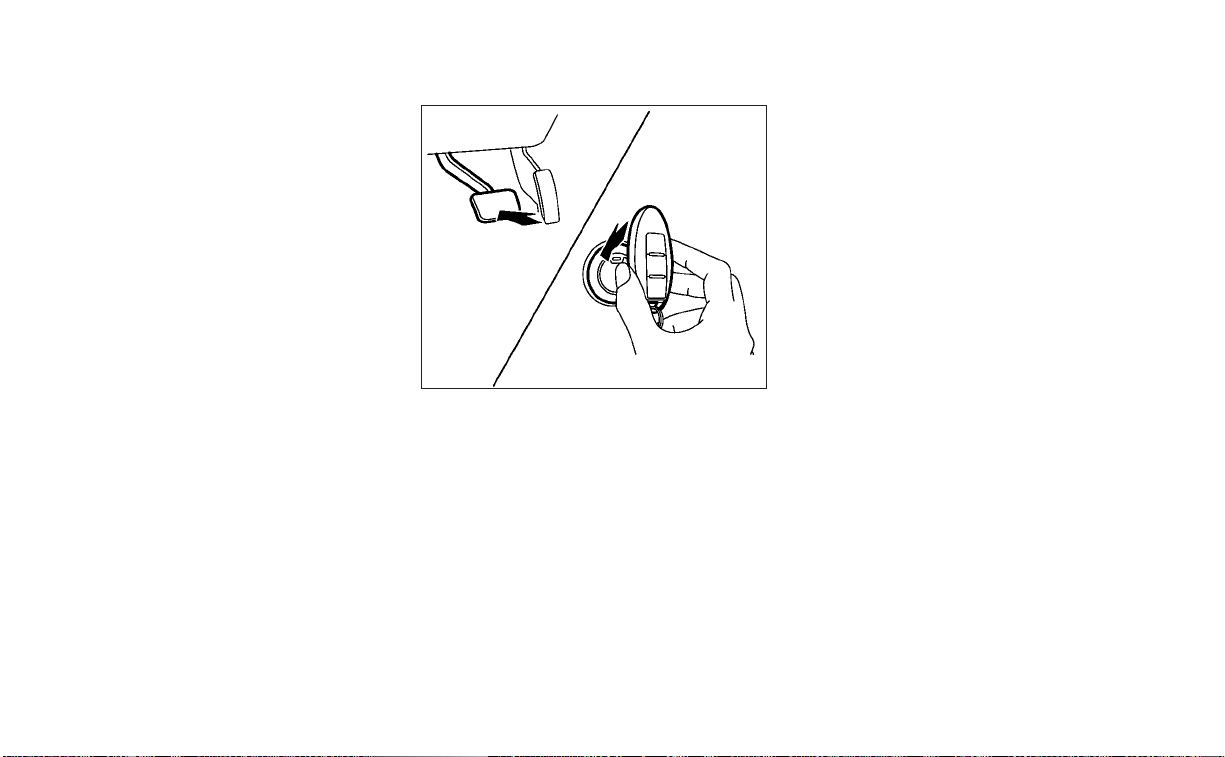
OFF
The ignition switch is in the OFF position
when the engine is turned off using the
ignition switch. No lights will illuminate on
the ignition switch.
AUTO ACC:
With the vehicle in the P (Park) position, the
Intelligent Key with you and the ignition
switch placed from the ON position to the
OFF position, the radio can still be used for
a period of time, or until the driver’s door is
opened.
After a period of time, functions such as
radio, navigation, and Bluetooth® Hands-
Free Phone System may be restarted by
pressing the POWER button/VOLUME con-
trol knob or the key fob unlock button. For
additional information, refer to the sepa-
rate NissanConnect® Owner’s Manual.
EMERGENCY ENGINE SHUT OFF
To shut off the engine in an emergency
situation while driving, perform the follow-
ing procedure:
• Rapidly push the ignition switch three
consecutive times in less than 1.5 sec-
onds, or
• Push and hold the ignition switch for
more than 2 seconds.
NISSAN INTELLIGENT KEY®
BATTERY DISCHARGE
If the battery of the NISSAN Intelligent Key®
is discharged or environmental conditions
interfere with the Intelligent Key operation,
start the engine according to the following
procedure:
1. Place the shift lever in the P (Park)
position.
2. Firmly apply the foot brake.
3. Touch the ignition switch with the Intel-
ligent Key as illustrated. (A chime will
sound.)
After step 3 is performed, when the igni-
tion switch is pushed without depress-
ing the brake pedal, the ignition switch
position will change to the ON position.
4. Push the ignition switch while depress-
ing the brake pedal within 10 seconds
after the chime sounds. The engine will
start.
NOTE:
• When the ignition switch is pushed to
the ON position or the engine is started
by the above procedure, the Intelligent
Key battery discharge indicator ap-
pears in the vehicle information dis-
play even when the Intelligent Key is
inside the vehicle. This is not a mal-
function. To turn off the Intelligent Key
battery discharge indicator, touch the
ignition switch with the Intelligent Key
again.
• If the Intelligent Key battery discharge
indicator appears, replace the battery
as soon as possible. For additional in-
formation, see “Battery replacement”
(P. 8-23).
SSD0860
Starting and driving 5-15

NISSAN VEHICLE IMMOBILIZER
SYSTEM
The NISSAN Vehicle Immobilizer System
will not allow the engine to start without
the use of the registered key.
If the engine fails to start using a registered
key (for example, when interference is
caused by another registered key, an auto-
mated toll road device or automatic pay-
ment device on the key ring), restart the
engine using the following procedure:
1. Leave the ignition switch in the ON posi-
tion for approximately 5 seconds.
2. Place the ignition switch in the OFF or
LOCK position, and wait approximately
10 seconds.
3. Repeat steps 1 and 2.
4. Restart the engine while holding the de-
vice (which may have caused the inter-
ference) separate from the registered
key.
If the no start condition re-occurs, NISSAN
recommends placing the registered key on
a separate key ring to avoid interference
from other devices.
• Make sure the area around the vehicle is
clear.
• Check fluid levels such as engine oil, cool-
ant, brake fluid, and windshield-washer
fluid as frequently as possible, or at least
whenever you refuel.
• Check that all windows and lights are
clean.
• Visually inspect tires for their appearance
and condition. Also check tires for proper
inflation.
• Lock all doors.
• Position seat and adjust headrests/head
restraints.
• Adjust inside and outside mirrors.
• Fasten seat belts and ask all passengers
to do likewise.
• Check the operation of warning lights
when the ignition switch is pushed to the
ON position. For additional information,
see “Warning lights, indicator lights and
audible reminders” (P. 2-9).
1. Apply the parking brake.
2. Move the shift lever to P (Park) or N (Neu-
tral). P (Park) is recommended.
The starter is designed not to operate
if the shift lever is in any of the driving
positions.
3. Push the ignition switch to the ON posi-
tion. Depress the brake pedal and push
the ignition switch to start the engine.
To start the engine immediately, push
and release the ignition switch while de-
pressing the brake pedal with the igni-
tion switch in any position.
• If the engine is very hard to start in
extremely cold weather or when re-
starting, depress the accelerator
pedal a little (approximately 1/3 to the
floor) and while holding, crank the en-
gine. Release the accelerator pedal
when the engine starts.
BEFORE STARTING THE ENGINE STARTING THE ENGINE
5-16 Starting and driving

• If the engine is very hard to start be-
cause it is flooded, depress the accel-
erator pedal all the way to the floor
and hold it. Push the ignition switch to
the ON position to start cranking the
engine. After 5 or 6 seconds, stop
cranking by pushing the ignition
switch to the LOCK position. After
cranking the engine, release the accel-
erator pedal. Crank the engine with
your foot off the accelerator pedal by
depressing the brake pedal and push-
ing the ignition switch to start the en-
gine. If the engine starts, but fails to
run, repeat the above procedure.
CAUTION
Do not operate the starter for more
than 15 seconds at a time. If the engine
does not start, push the ignition switch
to the OFF position and wait 10 seconds
before cranking again, otherwise the
starter could be damaged.
4. Warm-up:
Allow the engine to idle for at least 30
seconds after starting. Do not race the
engine while warming it up. Drive at a
moderate speed for a shor t distance
first, especially in cold weather. In cold
weather, keep the engine running for a
minimum of 2 to 3 minutes before shut-
ting it off. Starting and stopping the en-
gine over a short period of time may
make the vehicle more difficult to start.
5. To stop the engine, move the shift lever
to the P (Park) position and push the
ignition switch to the OFF position.
NOTE:
Care should be taken to avoid situa-
tions that can lead to potential battery
discharge and potential no-start con-
ditions such as:
1. Installation or extended use of elec-
tronic accessories that consume bat-
tery power when the engine is not
running (phone chargers, GPS, DVD
players, etc.).
2. The vehicle is not driven regularly
and/or only driven short distances.
In these cases, the battery may need to
be charged to maintain battery health.
REMOTE ENGINE START
Vehicles started with the Remote Engine
Start require the ignition switch to be
placed in the ON position before the shift
lever can be moved from the P (Park) posi-
tion. To place the ignition switch in the ON
position, follow these steps:
1. Make sure that the Intelligent Key is on
you.
2. Apply the brake.
3. Push the ignition switch once to the ON
position.
For additional information, see “NISSAN In-
telligent Key®” (P. 3-7).
Starting and driving 5-17

CONTINUOUSLY VARIABLE
TRANSMISSION (CVT)
WARNING
• Do not depress the accelerator pedal
while shifting from P (Park) or N (Neu-
tral) to R (Reverse), D (Drive), L (Low) or
manual shift mode (if so equipped).
Always depress the brake pedal until
shifting is completed. Failure to do so
could cause you to lose control and
have an accident.
• Cold engine idle speed is high, so use
caution when shifting into a forward
or reverse gear before the engine has
warmed up.
• Do not downshift abruptly on slip-
pery roads. This may cause a loss of
control.
• Never shift to either the P (Park) or R
(Reverse) position while the vehicle is
moving forward and P (Park) or D
(Drive) position while the vehicle is
reversing. This could cause an acci-
dent or damage the transmission.
CAUTION
• Except in an emergency, do not shift
to the N (Neutral) position while driv-
ing. Coasting with the transmission
in the N (Neutral) position may cause
serious damage to the transmission.
• To avoid possible damage to your ve-
hicle, when stopping the vehicle on
an uphill grade, do not hold the ve-
hicle by depressing the accelerator
pedal. The foot brake should be used
for this purpose.
The CVT in your vehicle is electronically
controlled to produce maximum power
and smooth operation.
Follow these procedures for maximum ve-
hicle performance and driving enjoyment.
NOTE:
Engine power may be automatically re-
duced to protect the CVT if the engine
speed increases quickly when driving on
slippery roads or while being tested on
some dynamometers.
Starting the vehicle
1. After starting the engine, fully depress
the foot brake pedal before moving the
shift lever out of the P (Park) position. The
Continuously Variable Transmission is
designed so the foot brake pedal
MUST be depressed before shifting
from P (Park) to any drive position
while the ignition switch is in the ON
position.The shift lever cannot be
moved out of P (Park) and into any of
the other gear positions if the ignition
switch is placed in the LOCK position.
LSD3074
DRIVING THE VEHICLE
5-18 Starting and driving

2. A screen is displayed for a period of time
that indicates the status of the driving
aid functions (if so equipped).
– AEB with Pedestrian Detection, LDW,
and BSW are enabled when the speci-
fied driving aid is shaded.
– I-LI is enabled when the driving aid is
solid.
– Use the
O
1
or
O
2
button to
navigate the settings screen. For ad-
ditional information, see “How to use
the vehicle information display”
(P. 2-19) or (P. 2-34)
3. Keep the foot brake pedal depressed
and move the shift lever to a driving
position.
4. Release the foot brake, then gradually
start the vehicle in motion.
5. Stop the vehicle completely before mov-
ing the shift lever to the P (Park) position.
WARNING
• Do not depress the accelerator pedal
while shifting from P (Park) or N (Neu-
tral) to R (Reverse), D (Drive), L (Low) or
manual shift mode (if so equipped).
Always depress the brake pedal until
shifting is completed. Failure to do so
could cause you to lose control and
have an accident.
• Cold engine idle speed is high, so use
caution when shifting into a forward
or reverse gear before the engine has
warmed up.
• Do not downshift abruptly on slip-
pery roads. This may cause a loss of
control.
• Never shift to either the P (Park) or R
(Reverse) position while the vehicle is
moving forward and P (Park) or D
(Drive) position while the vehicle is
reversing. This could cause an acci-
dent or damage the transmission.
CAUTION
• Except in an emergency, do not shift
to the N (Neutral) position while driv-
ing. Coasting with the transmission
in the N (Neutral) position may cause
serious damage to the transmission.
• To avoid possible damage to your ve-
hicle, when stopping the vehicle on
an uphill grade, do not hold the ve-
hicle by depressing the accelerator
pedal. The foot brake should be used
for this purpose.
Starting and driving 5-19

Shifting
To move the shift lever:
Press the button
O
A
while depress-
ing the brake pedal
Press the button
O
A
to shift
Shift without pressing the button
O
A
After starting the engine, fully depress the
brake pedal and move the shift lever from P
(Park) to any of the desired shift positions.
WARNING
Apply the parking brake if the shift le-
ver is in any position while the engine is
not running. Failure to do so could
cause the vehicle to move unexpect-
edly or roll away and result in serious
personal injury or property damage.
P (Park)
CAUTION
To prevent transmission damage, use
the P (Park) or R (Reverse) position only
when the vehicle is completely
stopped.
Use the P (Park) shift lever position when
the vehicle is parked or when starting the
engine. Make sure the vehicle is completely
stopped. The brake pedal should be de-
pressed to move the shift lever from N
(Neutral) or any drive position to P (Park).
Apply the parking brake. When parking on a
hill, apply the parking brake first, then move
the shift lever into the P (Park) position.
R (Reverse)
CAUTION
To prevent transmission damage, use
the P (Park) or R (Reverse) position only
when the vehicle is completely
stopped.
Use the R (Reverse) position to back up.
Make sure the vehicle is completely
stopped before selecting the R (Reverse)
position. The brake pedal must be de-
pressed to move the shift lever from P
(Park), N (Neutral) or any drive position to
R (Reverse).
N (Neutral)
Neither forward nor reverse gear is en-
gaged. The engine can be started in this
position. You may shift to N (Neutral) and
restart a stalled engine while the vehicle is
moving.
D (Drive)
Use this position for all normal forward
driving.
LSD2643
5-20 Starting and driving

L(Low)
Use this position for engine braking on
steep downhill gradients/climbing steep
slopes and whenever approaching sharp
bends. Do not use the L (Low) position in
any other circumstances.
Manual shift mode (if so
equipped)
When the shift lever is in the D (Drive) posi-
tion and the drive sport mode switch is
pushed, the transmission is ready for the
manual shift mode. Shift ranges can be
selected manually by pulling the right-side
or left-side paddle shifter.
When shifting up, pull the right side paddle
shifter (+)
O
B
. The transmission shifts to the
higher range.
When shifting down, pull the left side
paddle shifter (−)
O
A
. The transmission
shifts to the lower range.
When canceling the manual shift mode,
push the drive sport mode switch. The
transmission returns to the normal driving
mode. When you pull the paddle shifter
while in the D (Drive) position with the drive
sport mode switch pushed, the transmis-
sion will shift to the upper or lower range
temporarily. The transmission will auto-
matically return to the drive sport mode
after a short period of time. If you want to
return to the drive sport mode manually,
pull and hold the paddle shifter for about
1.5 seconds.
In the manual shift mode, the shift range is
displayed on the position indicator in the
meter.
Shift ranges up or down one by one as
follows:
1⇔ 2 ⇔ 3 ⇔ 4 ⇔ 5 ⇔ 6 ⇔ 7 ⇔ 8
M8 (8th) and M7 (7th)
Use this position for all normal forward
driving at highway speeds.
M6 (6th) and M5 (5th)
Use this position when driving up long
slopes or for engine braking when driving
down long slopes.
LSD2914
Starting and driving 5-21

M4 (4th), M3 (3rd) and M2 (2nd)
Use for hill climbing or engine braking on
downhill grades.
M1 (1st)
Use this position when climbing steep hills
slowly or driving slowly through deep snow,
sand or mud, or for maximum engine brak-
ing on steep downhill grades.
• Remember not to drive at high speeds for
extended periods of time in lower than
the 8th range. This reduces fuel economy.
When shifting up
Use the + (up) side paddle shifter. (Shifts to
higher range.)
When shifting down
Use the − (down) side paddle shifter. (Shifts
to lower range.)
When canceling the manual shift mode
To cancel manual shift mode, push the
drive sport mode switch on the shift lever
or press and hold either paddle shifter.
• In the manual shift mode, the trans-
mission may not shift to the selected
gear. This helps maintain driving per-
formance and reduces the chance of
vehicle damage or loss of control.
• In the manual shift mode, the trans-
mission may shift up automatically to a
higher range than selected if the en-
gine speed is too high. When the ve-
hicle speed decreases, the transmis-
sion automatically shifts down and
shifts to 1st gear before the vehicle
comes to a stop.
• Continuously Variable Transmission
(CVT) operation is limited to automatic
drive mode when CVT fluid temperature
is extremely low even if manual shift
mode is selected. This is not a malfunc-
tion. When CVT fluid warms up, manual
mode can be selected.
• When the CVT fluid temperature is high,
the shift range may upshift in lower rpm
than usual. This is not a malfunction.
Shift lock release
If the battery charge is low or discharged,
the shift lever may not be moved from the
P (Park) position even with the brake pedal
depressed and the shift lever button
pressed.
It will be necessary to jump start or have
your battery charged. For additional infor-
mation, see “Jump starting” (P. 6-11). Contact
a NISSAN dealer or a professional towing
service.
To move the shift lever, complete the fol-
lowing procedure:
LSD2644
5-22 Starting and driving

1. Push the ignition switch to the LOCK
position.
2. Apply the parking brake.
3. Using a protective cloth on the tip of a 3
mm screwdriver, remove the shift lock
release cover.
• If available, a plastic trim tool can also
be used.
4. Insert the small screwdriver in the shift
lock release slot and push down.
5. Move the shift lever to the N (Neutral)
position while holding down the shift
lock release.
If the shift lever cannot be moved out of P
(Park), have the transmission checked as
soon as possible. It is recommended that
you visit a NISSAN dealer for this service.
WARNING
If the shift lever cannot be moved from
the P (Park) position while the engine is
running and the brake pedal is de-
pressed, the stop lights may not work.
Malfunctioning stop lights could cause
an accident injuring yourself and
others.
Drive spor t mode switch
When the drive sport mode switch is
pushed with the shift lever in the D (Drive)
position, the drive sport mode indicator in
the instrument panel illuminates. For addi-
tional information, see “Drive sport mode
indicator” (P. 2-28) or (P. 2-44)
Use the drive sport mode when you need
improved engine braking.
To turn off the drive sport mode, push the
drive sport mode switch again. The drive
sport mode indicator will turn off.
Each time the engine is started, or when
the shift lever is shifted to any position
other than D (Drive), the drive sport mode
will automatically turn off.
Accelerator downshift
— in D (Drive) position —
For passing or hill climbing, depress the
accelerator pedal to the floor. This shifts
the transmission down into a lower gear,
depending on the vehicle speed.
High fluid temperature protection
mode
This transmission has a high fluid tem-
perature protection mode. If the fluid tem-
perature becomes too high (for example,
when climbing steep grades in high tem-
peratures with heavy loads, such as when
towing a trailer), engine power and, under
some conditions, vehicle speed will be de-
creased automatically to reduce the
chance of transmission damage. Vehicle
speed can be controlled with the accelera-
tor pedal, but the engine and vehicle speed
may be limited.
LSD3250
Drive sport mode
Starting and driving 5-23

Fail-safe
If the vehicle is driven under extreme
conditions, such as excessive wheel
spinning and subsequent hard braking,
the fail-safe system may be activated.
The Malfunction Indicator Light (MIL)
may come on to indicate the fail-safe
mode is activated. For additional infor-
mation, see “Malfunction Indicator Light
(MIL)” (P. 2-15). This will occur even if all
electrical circuits are functioning prop-
erly. In this case, place the ignition switch
in the OFF position and wait for 10 sec-
onds. Then push the switch back to the
ON position. The vehicle should return to
its normal operating condition. If it does
not return to its normal operating condi-
tion, have the transmission checked. It is
recommended that you visit a NISSAN
dealer for this service.
WARNING
When the high fluid temperature pro-
tection mode or fail-safe operation oc-
curs, vehicle speed may be gradually
reduced. The reduced speed may be
lower than other traffic, which could in-
crease the chance of a collision. Be es-
pecially careful when driving. If neces-
sary, pull to the side of the road at a safe
place and allow the transmission to re-
turn to normal operation, or have it re-
paired if necessary.
WARNING
• Be sure the parking brake is fully re-
leased before driving. Failure to do so
can cause brake failure and lead to
an accident.
• Do not release the parking brake
from outside the vehicle.
• Do not use the shift lever in place of
the parking brake. When parking, be
sure the parking brake is fully
engaged.
• To help avoid risk of injury or death
through unintended operation of the
vehicle and/or its systems, do not
leave children, people who require
the assistance of others or pets unat-
tended in your vehicle. Additionally,
the temperature inside a closed ve-
hicle on a warm day can quickly be-
come high enough to cause a signifi-
cant risk of injury or death to people
and pets.
PARKING BRAKE
5-24 Starting and driving
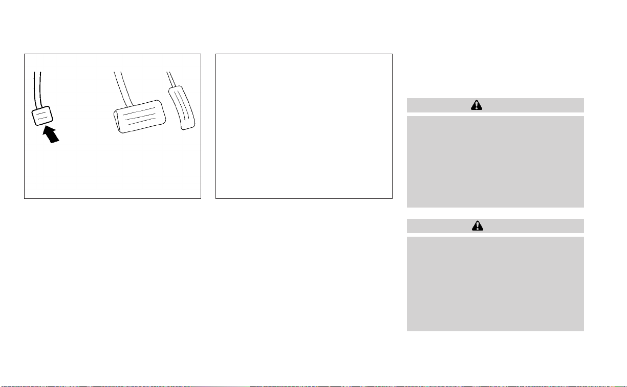
MANUAL PARKING BRAKE (pedal
type)
To engage: Firmly depress the parking
brake.
To release:
1. Firmly apply the foot brake.
2. Move the shift lever to the P (Park)
position.
3. Firmly depress the parking brake pedal
and it will release.
4. Before driving, be sure the brake warn-
ing light goes out.
ELECTRONIC PARKING BRAKE
(switch type)
The electronic parking brake can be ap-
plied or released automatically or by oper-
ating the parking brake switch.
Automatic operation
The electronic parking brake will apply au-
tomatically if the ignition switch is placed in
the OFF position when the brake force is
maintained by the automatic brake hold
function.
The electronic parking brake is automati-
cally released as soon as the vehicle starts
and the accelerator pedal is depressed
with the driver’s seat belt fastened.
WARNING
Before leaving the vehicle, move the
shift lever to the P (Park) position and
check that the electronic parking brake
warning light is illuminated to confirm
that the electronic parking brake is ap-
plied. The elec tronic parking brake
warning light will remain on for a pe-
riod of time after the driver’s door is
locked.
CAUTION
When parking in an area where the out-
side temperature is below 32°F (0°C),
the parking brake, if applied, may
freeze in place and may be difficult to
release.
For safe parking, it is recommended
that you place the shift lever in the P
(Park) position and securely block the
wheels.
LSD0158 LSD3210
Starting and driving 5-25

NOTE:
• To keep the electronic parking brake
released after the engine is turned off,
place the ignition switch in the OFF po-
sition, depress the brake pedal and
push down the parking brake switch
before opening the driver’s door.
• If a malfunction occurs in the elec-
tronic parking brake system (for ex-
ample, due to battery discharge), it is
recommended that you visit a NISSAN
dealer.
• If the shift lever is moved to the P (Park)
position when the brake force is main-
tained by the automatic brake hold
function, the electronic parking brake
will apply automatically.
• If the driver’s seat belt is unfastened
when the brake force is maintained by
the automatic brake hold function, the
electronic parking brake will apply
automatically.
• If the ignition switch is placed in the
OFF position when the brake force is
maintained by the automatic brake
hold function, the elec tronic parking
brake will apply automatically.
Manual operation
The electronic parking brake will not be au-
tomatically applied if the engine is stopped
without using the ignition switch (for ex-
ample, by engine stalling). In such a case,
you have to apply the parking brake
manually.
To apply: Pull the switch up
O
1
. The indica-
tor light
O
A
will illuminate.
To release: With the ignition switch in the
ON position, depress the brake pedal and
push the switch down
O
2
. The indicator
light
O
A
will turn off.
Before driving, check that the electronic
parking brake indicator light (
or PARK)
goes out. For additional information, see
“Warning lights, indicator lights and audible
reminders” (P. 2-9).
NOTE:
• A buzzer will sound if the vehicle is
driven without releasing the parking
brake. For additional information, see
“Warning lights, indicator lights and
audible reminders” (P. 2-9).
• While the electronic parking brake is
applied or released, an operating
sound is heard from the lower side of
the rear seat. This is normal and does
not indicate a malfunction.
• When the electronic parking brake is
frequently applied and released in a
short period of time, the parking brake
may not operate in order to prevent the
parking brake system from overheat-
ing. If this occurs, operate the elec-
tronic parking brake switch again after
waiting approximately 1 minute.
• If the electronic parking brake must be
applied while driving in an emergency,
pull up and hold the parking brake
switch. When you release the parking
brake switch, the parking brake will be
released.
•
While pulling up the electronic parking
brake switch during driving, the parking
brake is applied and a chime sounds.
The electronic parking brake indicator
light in the meter and in the parking
brake switch illuminates. This does not
indicate a malfunction. The electronic
parking brake indicator light in the me-
ter and in the parking brake switch turns
off when the parking brake is released.
5-26 Starting and driving

• When pulling the electronic parking
brake switch up with the ignition
switch in the OFF or AUTO ACC position,
the parking brake switch indicator
light will continue to illuminate for a
short period of time.
The automatic brake hold function main-
tains the braking force without the driver
having to depress the brake pedal when
the vehicle is stopped at a traffic light or
intersection. As soon as the driver de-
presses the accelerator pedal again, the
automatic brake hold function is deacti-
vated and the braking force is released.The
operating status of the automatic brake
hold can be displayed on the vehicle infor-
mation display.
WARNING
• The automatic brake hold function is
not designed to hold the vehicle on a
steep hill or slippery road. Never use
the automatic brake hold when the
vehicle is stopped on a steep hill or
slippery road. Failure to do so may
cause the vehicle to move.
• When the automatic brake hold func-
tion is activated but fails to maintain
the vehicle at a standstill, depress the
brake pedal to stop the vehicle. If the
vehicle unexpectedly moves due to
outside conditions, the chime may
sound and automatic brake hold
warning may illuminate in the vehicle
information display.
• Be sure to deactivate the automatic
brake hold function when using a car
wash or towing your vehicle.
• Make sure to place the shift lever in
the P (Park) position and apply the
parking brake when parking your ve-
hicle, entering or exiting the vehicle,
or loading luggage. Failure to do so
could cause the vehicle to move or
roll away unexpectedly and result in
serious personal injury or property
damage.
• If any of the following conditions oc-
cur, the automatic brake hold func-
tion may not function. Have the sys-
tem checked promptly. It is
recommended that you visit a
NISSAN dealer for this service. Failure
to operate the vehicle in accordance
with these conditions could cause
the vehicle to move or roll away un-
expectedly and result in serious per-
sonal injury or property damage.
– A warning message appears in the
vehicle information display.
– The indicator light on the auto-
matic brake hold switch does not
illuminate when the switch is
pushed.
AUTOMATIC BRAKE HOLD (if so
equipped)
Starting and driving 5-27

• The automatic brake hold function
will not be activated if the slip indica-
tor light, electronic parking brake
warning light or master warning light
illuminate and the chassis control
system fault message appears in the
vehicle information display.
• To maintain the braking force to keep
the vehicle to a standstill, a noise
may be heard. This is not a
malfunction.
HOW TO ACTIVATE/DEACTIVATE
THE AUTOMATIC BRAKE HOLD
FUNCTION
For additional information on activating
and deactivating the automatic brake hold
function, refer to the instructions outlined
in this section.
How to activate the automatic
brake hold function
1. With the ignition switch in the ON posi-
tion, push the automatic brake hold
switch
O
1
. The indicator light on the au-
tomatic brake hold switch
O
2
illuminates.
2. When the automatic brake hold function
goes into standby, the automatic brake
hold indicator light (white) illuminates.
To use the automatic brake hold function,
the following conditions need to be met:
• The driver’s seat belt is fastened.
• The electronic parking brake is released.
• The shift lever is not in the P (Park)
position.
• The vehicle is not parked on a steep hill.
NOTE:
The automatic brake hold function re-
sets to OFF every time the ignition
switch is switched from the OFF position
to the ON position.
LSD3211
5-28 Starting and driving

How to deactivate the automatic
brake hold function
While the automatic brake hold function is
activated, push the automatic brake hold
switch to turn off the automatic brake hold
indicator light and deactivate the auto-
matic brake hold function. To deactivate
the automatic brake hold function while
the brake force has been maintained by
the automatic brake hold function, depress
the brake pedal and push the automatic
brake hold switch.
WARNING
Make sure to firmly depress and hold
the brake pedal when turning off the
automatic brake hold function while
the brake force is applied. When the au-
tomatic brake hold func tion is deacti-
vated, the brake force will be released.
This could cause the vehicle to move or
roll away unexpectedly. Failure to pre-
vent the vehicle from rolling may result
in serious personal injury or property
damage.
HOW TO USE THE AUTOMATIC
BRAKE HOLD FUNCTION
For additional information on using the au-
tomatic brake hold function, refer to the
instructions outlined in this section.
To maintain braking force
automatically
With the automatic brake hold function ac-
tivated and the automatic brake hold indi-
cator light (white) illuminated on the meter,
depress the braking pedal to stop the ve-
hicle. The brake force is automatically
maintained without your foot depressed
on the brake pedal. While the brake hold is
maintained, the automatic brake hold indi-
cator light (green) illuminates on the meter.
To start the vehicle from a
standstill
With the shift lever not in the P (Park) or N
(Neutral) position, depress the accelerator
pedal while the brake force is maintained.
The brake force will automatically be re-
leased to restart the vehicle.
The automatic brake hold indicator light
(white) on the meter illuminates and the
automatic brake hold returns to standby.
Parking
When the shift lever is in the P (Park) posi-
tion with the brake force maintained by the
automatic brake hold function, the parking
brake will automatically be applied and the
brake force of the automatic brake hold will
be released. The automatic brake hold in-
dicator light turns off. When the parking
brake is applied with the brake force main-
tained by the automatic brake hold func-
tion, the brake force of the automatic brake
hold will be released. The automatic brake
hold indicator light turns off.
NOTE:
• Under the following conditions, the
parking brake will automatically be ap-
plied and the brake force of the auto-
matic brake hold will be released:
– The braking force is applied by the
automatic brake hold function for 3
minutes or longer.
– The driver's seat belt is unfastened.
– The ignition switch is placed in the
OFF position.
– If a malfunction occurs in the auto-
matic brake hold function.
Starting and driving 5-29

• When the vehicle stops, but the brake
force is not automatically applied, de-
press the brake pedal firmly until the
automatic brake hold indicator light
(green) illuminates.
The TSR system provides the driver with
information about the most recently de-
tected speed limit. The system captures
the road sign information with the multi-
sensing front camera unit
O
1
located on
the windshield in front of the inside rear-
view mirror and displays the detected
signs in the vehicle information display. For
vehicles equipped with a navigation sys-
tem, the speed limit displayed is based on a
combination of navigation system data
and live camera recognition. TSR informa-
tion is always displayed at the top of the
vehicle information display, and optionally
in the main central area of the display
screen.
WARNING
The TSR system is only intended to be a
support device to help provide the
driver with information. It is not a re-
placement for the driver’s at tention to
traffic conditions or responsibility to
drive safely. It cannot prevent acci-
dents due to carelessness. It is the driv-
er’s responsibility to stay alert and
drive safely at all times.
LSD3212
TRAFFIC SIGN RECOGNITION (TSR) (if
so equipped)
5-30 Starting and driving

SYSTEM OPERATION
The Traffic Sign Recognition (TSR) system
displays the following types of road signs:
CAUTION
• The TSR system is intended as an aid
to careful driving. It is the driver’s re-
sponsibility to stay alert, drive safely,
and observe all road regulations that
currently apply, including looking out
for road signs.
• The TSR system may not function
properly under the following
conditions:
– When the road sign is not clearly
visible, for example, due to dam-
age or weather conditions.
– When rain, snow or dirt adheres to
the windshield in front of the
multi-sensing camera unit.
– When the headlights are not
bright, for example, due to dirt on
the lens or if the aiming is not ad-
justed properly.
– When strong light enters the cam-
era unit. (For example, the light di-
rectly shines on the front of the
vehicle at sunrise or sunset.)
– When a sudden change in bright-
ness occurs. (For example, when
the vehicle enters or exits a tunnel
or under a bridge.)
– If there are deviations in relation
to the navigation, for example due
to changes in the road routing.
– When overtaking buses or trucks
with speed stickers.
LSD3925 LSD3940
Starting and driving 5-31

TURNING THE TRAFFIC SIGN
RECOGNITION (TSR) SYSTEM ON
AND OFF
Perform the following steps to enable or
disable the TSR system.
1. Press the
button until “Settings” dis-
plays in the vehicle information display.
Use the
button to select “Driver As-
sistance.” Then press the OK button.
2. Select “Speed Limit Sign” and press the
OK button to turn the system on or off.
SYSTEM TEMPORARILY
UNAVAILABLE
If the vehicle is parked in direct sunlight
under high temperature conditions (over
approximately 104°F [40°C]) and then
started, the TSR system may be deacti-
vated automatically. The “Unavailable: High
Cabin Temperature” warning message will
appear in the vehicle information display.
Action to take:
When the interior temperature is reduced,
the TSR system will resume operating
automatically.
SYSTEM MALFUNCTION
If the TSR system malfunctions, it will be
turned off automatically and the system
“Malfunction” warning message will appear
in the vehicle information display.
Action to take:
If the TSR “Malfunction” message appears,
pull off the road at a safe location and stop
the vehicle. Turn the engine off and restart
the engine. If the TSR “Malfunction” mes-
sage continues to appear, have the system
checked. It is recommended that you visit a
NISSAN dealer for this service.
SYSTEM MAINTENANCE
The TSR system uses the same multi-
sensing front camera unit that is used by
the Lane Depar ture Warning (LDW) system,
located in front of the interior rearview mir-
ror. For additional information, see ”System
maintenance” (P. 5-39).
LSD3243
5-32 Starting and driving

WARNING
Failure to follow the warnings and in-
structions for proper use of the LDW
system could result in serious injury or
death.
• This system is only a warning device
to inform the driver of a potential un-
intended lane departure. It will not
steer the vehicle or prevent loss of
control. It is the driver’s responsibility
to stay alert, drive safely, keep the
vehicle in the traveling lane, and be in
control of the vehicle at all times.
The LDW system will operate when the ve-
hicle is driven at speeds of approximately
37 mph (60 km/h) and above, and only
when the lane markings are clearly visible
on the road.
The LDW system monitors the lane mark-
ers on the traveling lane using the camera
unit
O
A
located above the inside mirror.
The LDW system warns the driver that the
vehicle is beginning to leave the driving
lane with an indicator and a steering wheel
vibration. For additional information, see
“LDW system operation” (P. 5-34).
LSD3213
LANE DEPARTURE WARNING (LDW)
Starting and driving 5-33

LDW SYSTEM OPERATION
LSD3291
For vehicles with the 7 inch (18 cm) display
5-34 Starting and driving

The LDW system provides a lane departure
warning function when the vehicle is driven
at speeds of approximately 37 mph (60
km/h) and above and the lane markings
are clear. When the vehicle approaches ei-
ther the left or the right side of the traveling
lane, the steering wheel will vibrate and the
LDW indicator on the instrument panel will
blink to alert the driver.
The warning function will stop when the
vehicle returns inside of the lane markers.
LSD3902
For vehicles with the 5 inch (13 cm) display
Starting and driving 5-35

HOW TO ENABLE/DISABLE THE
LDW SYSTEM
Perform the following steps to enable or
disable the LDW system.
For vehicles with the 7 inch (18 cm)
display.
1. Press the
button until “Settings” dis-
plays in the vehicle information display.
Use the
button to select “Driver As-
sistance.” Then press the OK button.
2. Select “Lane” and press the OK button.
3. Select “Lane Departure Warning” and
press the OK button to turn the system
on or off.
LSD3215
For vehicles with the 7 inch (18 cm) display
5-36 Starting and driving

For vehicles with the 5 inch (13 cm)
display.
1. Press the
button until “Settings” dis-
plays in the vehicle information display.
Use the
button to select “Driver As-
sistance.” Then press the OK button.
2. Select “Driving Aids” and press the OK
button.
3. Select “Lane” and press the OK button.
4. Select “Lane (LDW)” and press the OK
button to turn the system on or off.
LSD3926
For vehicles with the 5 inch (13 cm) display
Starting and driving 5-37

LDW SYSTEM LIMITATIONS
WARNING
Listed below are the system limitations
for the LDW system. Failure to follow
the warnings and instructions for
proper use of the LDW system could re-
sult in serious injury or death.
• The system will not operate at
speeds below approximately 37 mph
(60 km/h) or if it cannot detect lane
markers.
• Do not use the LDW system under the
following conditions as it may not
function properly:
– During bad weather (rain, fog,
snow, etc.).
– When driving on slippery roads,
such as on ice or snow.
– When driving on winding or un-
even roads.
– When there is a lane closure due to
road repairs.
– When driving in a makeshift or
temporary lane.
– When driving on roads where the
lane width is too narrow.
– When driving without normal tire
conditions (for example, tire wear,
low tire pressure, installation of
spare tire, tire chains, nonstan-
dard wheels).
– When the vehicle is equipped with
non-original brake parts or sus-
pension parts.
– When you are towing a trailer or
other vehicle.
• The system may not function prop-
erly under the following conditions:
– On roads where there are multiple
parallel lane markers; lane mark-
ers that are faded or not painted
clearly; yellow painted lane mark-
ers; non-standard lane markers;
or lane markers covered with wa-
ter, dirt, snow, etc.
– On roads where the discontinued
lane markers are still detectable.
– On roads where there are sharp
curves.
–
On roads where there are sharply
contrasting objects, such as shad-
ows, snow, water, wheel ruts, seams
or lines remaining after road re-
pairs. (The LDW system could detect
these items as lane markers.)
– On roads where the traveling lane
merges or separates.
– When the vehicle’s traveling direc-
tion does not align with the lane
marker.
– When traveling close to the ve-
hicle in front of you, which ob-
structs the lane camera unit de-
tection range.
– When rain, snow, dirt or an object
adheres to the windshield in front
of the lane camera unit.
– When the headlights are not
bright due to dirt on the lens or if
the aiming is not adjusted
properly.
– When strong light enters the lane
camera unit. (For example, the
light directly shines on the front of
the vehicle at sunrise or sunset.)
– When a sudden change in bright-
ness occurs. (For example, when
the vehicle enters or exits a tunnel
or under a bridge.)
5-38 Starting and driving

SYSTEM TEMPORARILY
UNAVAILABLE
If the vehicle is parked in direct sunlight
under high temperature conditions (over
approximately 104°F [40°C]) and then
started, the LDW system may be deacti-
vated automatically and the following
message will appear in the vehicle infor-
mation display: “Unavailable: High Cabin
Temperature” or “Not available High cabin
temperature”.
When the interior temperature is reduced,
the LDW system will resume operating
automatically.
The LDW system is not designed to warn
under the following conditions:
• When you operate the lane change signal
and change traveling lanes in the direc-
tion of the signal. (The LDW system will
become operable again approximately 2
seconds after the lane change signal is
turned off.)
• When the vehicle speed lowers to less
than approximately 37 mph (60 km/h).
After the above conditions have finished
and the necessary operating conditions
are satisfied, the LDW functions will resume.
SYSTEM MALFUNCTION
If the LDW system malfunctions, it will can-
cel automatically and “Not Available Sys-
tem Malfunction” or “System fault” will ap-
pear in the vehicle information display. If
“Not Available System Malfunction” or “Sys-
tem fault” appears in the vehicle informa-
tion display, pull off the road to a safe loca-
tion and stop the vehicle. Place the shift
lever in the P (Park) position and the ignition
switch in the OFF position and restart the
engine/motor. If “Not Available System Mal-
function” or “System fault” continues to ap-
pear in the vehicle information display,
have the system checked. It is recom-
mended that you visit a NISSAN dealer for
this service.
SYSTEM MAINTENANCE
The lane camera unit
O
1
for the LDW sys-
tem is located above the inside mirror. To
keep the proper operation of the LDW sys-
tem and prevent a system malfunction, be
sure to observe the following:
• Always keep the windshield clean.
• Do not attach a sticker (including trans-
parent material) or install an accessory
near the camera unit.
LSD3484
Starting and driving 5-39

• Do not place reflective materials, such as
white paper or a mirror, on the instru-
ment panel. The reflection of sunlight
may adversely affect the camera unit’s
capability of detecting the lane markers.
• Do not strike or damage the areas
around the camera unit. Do not touch the
camera lens or remove the screw located
on the camera unit. If the camera unit is
damaged due to an accident, it is recom-
mended that you visit a NISSAN dealer.
WARNING
Failure to follow the warnings and in-
structions for proper use of the I-LI sys-
tem could result in serious injury or
death.
• The I-LI system will not steer the ve-
hicle or prevent loss of control. It is
the driver’s responsibility to stay
alert, drive safely, keep the vehicle in
the traveling lane, and be in control of
the vehicle at all times.
• The I-LI system is primarily intended
for use on well-developed freeways
or highways. It may not detect the
lane markers in certain road,
weather, or driving conditions.
The I-LI system must be turned on with the
ProPILOT Assist switch (for vehicles with
ProPILOT Assist) on the steering wheel, ev-
ery time the ignition is placed in the ON
position.
The I-LI system will operate when the ve-
hicle is driven at speeds of approximately
37 mph (60 km/h) and above, and only
when the lane markings are clearly visible
on the road.
The I-LI system warns the driver when the
vehicle has left the center of the traveling
lane with an indicator and a steering wheel
vibration. The system helps assist the
driver to return the vehicle to the center of
the traveling lane by applying the brakes to
the left or right wheels individually (for a
short period of time).
The I-LI system monitors the lane markers
on the traveling lane using the camera unit
O
A
located above the inside mirror.
LSD3213
INTELLIGENT LANE INTERVENTION
(I-LI) (if so equipped)
5-40 Starting and driving

I-LI SYSTEM OPERATION
䊊
1
Lane Departure Warning (LDW)
indicator
䊊
2
Intelligent Lane Intervention (I-LI) indi-
cator (if so equipped)
䊊
3
ProPILOT Assist switch (for vehicles
with ProPILOT Assist)
The I-LI system operates above approxi-
mately 37 mph (60 km/h). When the vehicle
approaches either the left or the right side
of the traveling lane, the steering wheel will
vibrate and the LDW indicator (orange) on
the instrument panel will blink to alert the
driver. Then, the I-LI system will automati-
cally apply the brakes for a short period of
time to help assist the driver to return the
vehicle to the center of the traveling lane.
To turn on the I-LI system, push the ProPI-
LOT Assist switch (for vehicles with ProPI-
LOT Assist) on the steering wheel after
starting the engine/motor. The I-LI indica-
tor on the instrument panel will illuminate.
Push the ProPILOT Assist switch again to
turn off the I-LI system. The I-LI indicator will
turn off.
LSD3309
Starting and driving 5-41

HOW TO ENABLE/DISABLE THE I-LI
SYSTEM
Perform the following steps to enable or
disable the I-LI system.
1. Press the
button until “Settings” dis-
plays in the vehicle information display.
Use the
button to select “Driver As-
sistance.” Then press the OK button.
2. Select “Lane” and press the OK button.
3. Select “Lane Departure Prevention” and
press the OK button.
4. Push the ProPILOT Assist switch to turn
the system on or off.
NOTE:
When Lane Departure Prevention is en-
abled in the settings menu, turning the
ProPILOT Assist system (if so equipped)
on will activate the I-LI system at the
same time. If Lane Departure Prevention
is not enabled in the settings menu, I-LI
will automatically activate when the Pro-
PILOT Assist system is “SET.” For addi-
tional information, see “Intelligent Lane
Intervention (I-LI)” (P. 5-40).
LSD3215
5-42 Starting and driving

I-LI SYSTEM LIMITATIONS
WARNING
Listed below are the system limitations
for the I-LI system. Failure to follow the
warnings and instructions for proper
use of the I-LI system could result in
serious injury or death.
• The I-LI system may activate if you
change lanes without first activating
your turn signal or, for example, if a
construction zone directs traffic to
cross an existing lane marker. If this
occurs you may need to apply correc-
tive steering to complete your lane
change.
• Because the I-LI may not activate un-
der the road, weather, and lane
marker conditions described in this
section, it may not activate every
time your vehicle begins to leave its
lane and you will need to apply cor-
rective steering.
• When the I-LI system is operating,
avoid excessive or sudden steering
maneuvers. Otherwise, you could
lose control of the vehicle.
• The I-LI system will not operate at
speeds below approximately 37 mph
(60 km/h) or if it cannot detect lane
markers.
• Do not use the I-LI system under the
following conditions as it may not
function properly:
– During bad weather (rain, fog,
snow, etc.).
– When driving on slippery roads,
such as on ice or snow.
– When driving on winding or un-
even roads.
– When there is a lane closure due to
road repairs.
– When driving in a makeshift or
temporary lane.
– When driving on roads where the
lane width is too narrow.
– When driving without normal tire
conditions (for example, tire wear,
low tire pressure, installation of
spare tire, tire chains, non-
standard wheels).
– When the vehicle is equipped with
nonoriginal brake parts or sus-
pension parts.
– When you are towing a trailer or
other vehicle.
– On roads where there are multiple
parallel lane markers; lane mark-
ers that are faded or not painted
clearly; yellow painted lane mark-
ers; non-standard lane markers;
or lane markers covered with wa-
ter, dirt, snow, etc.
– On roads where discontinued lane
markers are still detectable.
– On roads where there are sharp
curves.
– On roads where there are sharply
contrasting objects, such as shad-
ows, snow, water, wheel ruts,
seams or lines remaining after
road repairs. (The I-LI system
could detect these items as lane
markers.)
– On roads where the traveling lane
merges or separates.
– When the vehicle’s traveling direc-
tion does not align with the lane
marker.
– When traveling close to the ve-
hicle in front of you, which ob-
structs the lane camera unit de-
tection range.
Starting and driving 5-43

– When rain, snow or dirt adheres to
the windshield in front of the lane
camera unit.
– When the headlights are not
bright due to dirt on the lens or if
the aiming is not adjusted
properly.
– When strong light enters the lane
camera unit. (For example, the
light directly shines on the front of
the vehicle at sunrise or sunset.)
– When a sudden change in bright-
ness occurs. (For example, when
the vehicle enters or exits a tunnel
or under a bridge.)
While the I-LI system is operating, you may
hear a sound of brake operation. This is
normal and indicates that the I-LI system is
operating properly.
SYSTEM TEMPORARILY
UNAVAILABLE
Condition A:
The warning and assist functions of the I-LI
system are not designed to work under the
following conditions:
• When you operate the lane change signal
and change the traveling lanes in the di-
rection of the signal. (The I-LI system will
be deactivated for approximately 2 sec-
onds after the lane change signal is
turned off.)
• When the vehicle speed lowers to less
than approximately 37 mph (60 km/h).
After the above conditions have finished
and the necessary operating conditions
are satisfied, the warning and assist func-
tions will resume.
Condition B:
The assist function of the I-LI system is not
designed to work under the following con-
ditions (warning is still functional):
• When the brake pedal is depressed.
• When the steering wheel is turned as far
as necessary for the vehicle to change
lanes.
• When the vehicle is accelerated during
I-LI system operation.
• When the Intelligent Cruise Control (ICC)
approach warning occurs.
• When the hazard warning flashers are
operated.
• When driving on a curve at high speed.
After the above conditions have finished
and the necessary operating conditions
are satisfied, the I-LI system application of
the brakes will resume.
Condition C:
If the following messages appear in the
vehicle information display, the I-LI system
will be turned off automatically.
• “Not Available Poor Road Conditions”:
When the VDC system (except Traction
Control System [TCS] function) or ABS
operates.
• “Currently not available”:
When the VDC system is turned off.
Action to take:
When the above conditions no longer exist,
turn off the I-LI system. Push the ProPILOT
Assist switch (for vehicles with ProPILOT
Assist) on the steering wheel again to turn
the I-LI system back on.
5-44 Starting and driving

Temporary disabled status at high
temperature:
If the vehicle is parked in direct sunlight
under high temperature conditions (over
approximately 104°F [40°C]) and then the
I-LI system is turned on, the I-LI system
may be deactivated automatically and the
following message will appear on the ve-
hicle information display: “Unavailable: High
Cabin Temperature.” When the interior
temperature is reduced, the system will re-
sume operating automatically.
SYSTEM MALFUNCTION
If the I-LI system malfunctions, it will cancel
automatically. The LDW indicator (orange)
will illuminate in the display. If the LDW indi-
cator (orange) illuminates in the display,
pull off the road to a safe location and stop
the vehicle. Turn the engine/motor off and
restart the engine/motor. If the LDW indica-
tor (orange) continues to illuminate, have
the I-LI system checked. It is recom-
mended that you visit a NISSAN dealer for
this service.
SYSTEM MAINTENANCE
The lane camera unit
O
1
for the I-LI system
is located above the inside mirror. To keep
the proper operation of the I-LI system and
prevent a system malfunction, be sure to
observe the following:
• Always keep the windshield clean.
• Do not attach a sticker (including trans-
parent material) or install an accessory
near the camera unit.
• Do not place reflective materials, such as
white paper or a mirror, on the instru-
ment panel. The reflection of sunlight
may adversely affect the camera unit’s
capability of detecting the lane markers.
• Do not strike or damage the areas
around the camera unit. Do not touch the
camera lens or remove the screw located
on the camera unit. If the camera unit is
damaged due to an accident, it is recom-
mended that you visit a NISSAN dealer.
LSD3484
Starting and driving 5-45
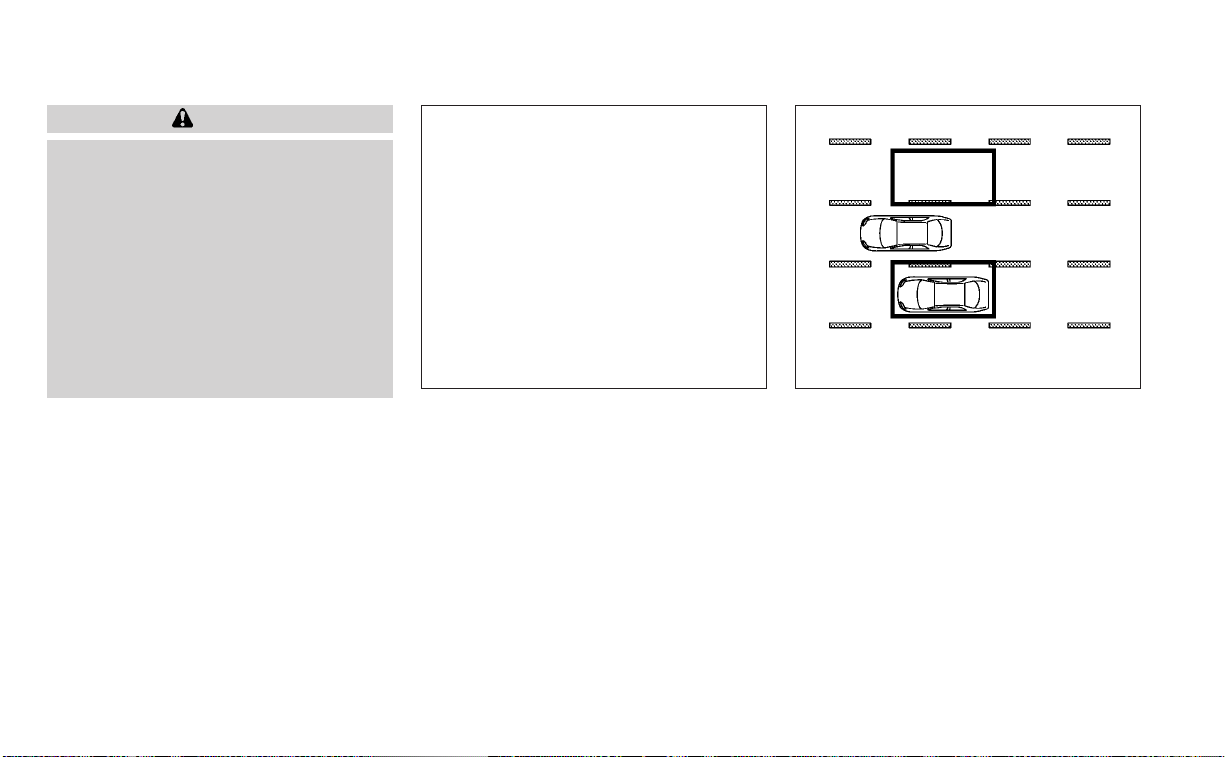
WARNING
Failure to follow the warnings and in-
structions for proper use of the BSW
system could result in serious injury or
death.
• The BSW system is not a replacement
for proper driving procedures and is
not designed to prevent contact with
vehicles or objects. When changing
lanes, always use the side and rear
mirrors and turn and look in the di-
rection your vehicle will move to en-
sure it is safe to change lanes. Never
rely solely on the BSW system.
The BSW system helps alert the driver of
other vehicles in adjacent lanes when
changing lanes.
The BSW system uses radar sensors
O
1
installed near the rear bumper to detect
other vehicles in an adjacent lane.
The radar sensors can detect vehicles on
either side of your vehicle within the detec-
tion zone shown as illustrated. This detec-
tion zone starts from the outside mirror of
your vehicle and extends approximately 10
ft (3.0 m) behind the rear bumper, and ap-
proximately 10 ft (3.0 m) sideways.
LSD3286 SSD1030
Detection zone
BLIND SPOT WARNING (BSW) (if so
equipped)
5-46 Starting and driving

LSD3313
For vehicles with the 7 inch (18 cm) display
Starting and driving 5-47

1. Side BSW/RCTA Indicator Light
2. BSW indicator
BSW SYSTEM OPERATION
The BSW system operates above approxi-
mately 20 mph (32 km/h).
If the radar sensors detect a vehicle in the
detection zone, the side BSW/RCTA indica-
tor light (1) illuminates. If the turn signal is
then activated, the system chimes (twice),
the side BSW/RCTA indicator light flashes
and the BSW indicator illuminates (yellow)
in the vehicle information display. The side
BSW/RCTA indicator light continues to
flash until the detected vehicle leaves the
detection zone.
The side BSW/RCTA indicator light illumi-
nates for a few seconds when the ignition
switch is placed in the ON position.
If a vehicle comes into the detection zone
after the driver activates the turn signal,
then only the side BSW/RCTA indicator light
flashes and no chime sounds. For addi-
tional information, see “BSW driving situa-
tions” (P. 5-52).
The BSW system automatically turns on
every time the engine is started, as long as
it is activated using the settings menu on
the vehicle information display.
LSD3904
For vehicles with the 5 inch (13 cm) display
5-48 Starting and driving

HOW TO ENABLE/DISABLE THE
BSW SYSTEM
Perform the following steps to enable or
disable the BSW system.
For vehicles with the 7 inch (18 cm)
display.
1. Press the
button until “Settings” dis-
plays in the vehicle information display.
Use the
button to select “Driver As-
sistance.” Then press the OK button.
2. Select “Blind Spot” and press the OK
button.
3. Select “Blind Spot Warning” and press
the OK button to turn the system on or
off.
LSD3487
For vehicles with the 7 inch (18 cm) display
Starting and driving 5-49

For vehicles with the 5 inch (13 cm)
display.
1. Press the
button until “Settings” dis-
plays in the vehicle information display.
Use the
button to select “Driver As-
sistance.” Then press the OK button.
2. Select “Driving Aids” and press the OK
button.
3. Select “Blind Spot” and press the OK
button.
4. Select “Blind Spot (BSW)” and press the
OK button to turn the system on or off.
NOTE:
When enabling/disabling the system,
the system will retain current settings
even if the engine is restarted.
LSD3927
For vehicles with the 5 inch (13 cm) display
5-50 Starting and driving

BSW SYSTEM LIMITATIONS
WARNING
Listed below are the system limitations
for the BSW system. Failure to operate
the vehicle in accordance with these
system limitations could result in seri-
ous injury or death.
• The BSW system cannot detect all ve-
hicles under all conditions.
• The radar sensors may not be able to
detect and activate BSW when cer-
tain objects are present such as:
– Pedestrian, bicycles, animals.
– Vehicles such as motorcycles, low
height vehicles, or high ground
clearance vehicles.
– Oncoming vehicles.
– Vehicles remaining in the detec-
tion zone when you accelerate
from a stop.
– A vehicle merging into an adjacent
lane at a speed approximately the
same as your vehicle.
– A vehicle approaching rapidly
from behind.
– A vehicle which your vehicle over-
takes rapidly.
– A vehicle that passes through the
detection zone quickly.
– When overtaking several vehicles
in a row, the vehicles after the first
vehicle may not be detected if
they are traveling close together.
• The radar sensors’ detection zone is
designed based on a standard lane
width. When driving in a wider lane,
the radar sensors may not detect ve-
hicles in an adjacent lane. When driv-
ing in a narrow lane, the radar sen-
sors may detect vehicles driving two
lanes away.
• The radar sensors are designed to ig-
nore most stationary objects; how-
ever, objects such as guardrails,
walls, foliage and parked vehicles
may occasionally be detected. This is
a normal operation condition.
• The following conditions may reduce
the ability of the radar to detect other
vehicles:
– Severe weather
– Road spray
– Ice/frost/snow/dirt build-up on
the vehicle
• Do not attach stickers (including
transparent material), install acces-
sories or apply additional paint near
the radar sensors. These conditions
may reduce the ability of the radar to
detect other vehicles.
• Excessive noise (for example, audio
system volume, open vehicle win-
dow) will interfere with the chime
sound, and it may not be heard.
Starting and driving 5-51

BSW DRIVING SITUATIONS
Indicator on
Indicator off
Indicator flashing
Another vehicle approaching
from behind
Illustration 1: The side BSW/RCTA indicator
light illuminates if a vehicle enters the de-
tection zone from behind in an adjacent
lane.
NOTE:
• The radar sensors may not detect ve-
hicles which are approaching rapidly
from behind.
Illustration 2: If the driver activates the
turn signal when another vehicle is in the
detection zone, then the system chimes
(twice) and the side BSW/RCTA indicator
light flashes.
NOTE:
• The radar sensors may not detect ve-
hicles which are approaching rapidly
from behind.
• If the driver activates the turn signal
before a vehicle enters the detection
zone, the side BSW/RCTA indicator
light will flash but no chime will sound
when the other vehicle is detected.
LSD2299
Illustration 1 – Approaching from behind
LSD2300
Illustration2–Approaching from behind
5-52 Starting and driving

Overtaking another vehicle
Illustration 3: The side BSW/RCTA indica-
tor light illuminates if you overtake a ve-
hicle and that vehicle stays in the detection
zone for approximately 2 seconds.
Illustration 4: If the driver activates the
turn signal while another vehicle is in the
detection zone, then the system chimes
(twice) and the side BSW/RCTA indicator
light flashes.
NOTE:
• When overtaking several vehicles in a
row, the vehicles after the first vehicle
may not be detected if they are travel-
ing close together.
• The radar sensors may not detect
slower m oving vehicles if they are
passed quickly.
• If the driver activates the turn signal
before a vehicle enters the detection
zone, the side BSW/RCTA indicator
light will flash but no chime will sound
when the other vehicle is detected.
LSD2302
Illustration3–Overtaking another
vehicle
LSD2303
Illustration4–Overtaking another
vehicle
Starting and driving 5-53

Entering from the side
Illustration 5: The side BSW/RCTA indicator
light illuminates if a vehicle enters the de-
tection zone from either side.
Illustration 6: If the driver activates the
turn signal while another vehicle is in the
detection zone, then the system chimes
(twice) and the side BSW/RCTA indicator
light flashes.
NOTE:
• If the driver activates the turn signal
before a vehicle enters the detection
zone, the side BSW/RCTA indicator
light will flash but no chime will sound
when the other vehicle is detected.
• The radar sensors may not detect a ve-
hicle which is traveling at about the
same speed as your vehicle when it en-
ters the detection zone.
LSD2305
Illustration 5 – Entering from the side
LSD2308
Illustration 6 – Entering from the side
5-54 Starting and driving

SYSTEM TEMPORARILY
UNAVAILABLE
When radar blockage is detected, the sys-
tem will be deactivated automatically. The
“Unavailable: Side Radar Obstruction”
warning message will appear in the vehicle
information display.
The system is not available until the condi-
tions no longer exist.
The radar sensors may be blocked by tem-
porary ambient conditions such as splash-
ing water, mist or fog. The blocked condi-
tion may also be caused by objects such as
ice, frost or dirt obstructing the radar
sensors.
NOTE:
If the BSW system stops working, the
RCTA system will also stop working.
Action to take:
When the above conditions no longer exist,
the system will resume automatically.
LSD3292
For vehicles with the 7 inch (18 cm) display
Starting and driving 5-55

Malfunction
If the BSW system malfunctions, it will turn
off automatically. The system malfunction
warning message with the BSW indicator
(orange) will appear in the vehicle informa-
tion display.
NOTE:
If the BSW system stops working, the
RCTA system will also stop working.
Action to take:
Stop the vehicle in a safe location, place the
vehicle in the P (Park) position, turn the en-
gine off and restart the engine. If the mes-
sage continues to appear, have the system
checked. It is recommended that you visit a
NISSAN dealer for this service.
LSD3941
For vehicles with the 5 inch (13 cm) display
5-56 Starting and driving

SYSTEM MAINTENANCE
The two radar sensors
O
1
for the BSW and
RCTA systems are located near the rear
bumper. Always keep the area near the ra-
dar sensors clean.
The radar sensors may be blocked by tem-
porary ambient conditions such as splash-
ing water, mist or fog.
The blocked condition may also be caused
by objects such as ice, frost or dirt ob-
structing the radar sensors.
Check for and remove objects obstructing
the area around the radar sensors.
Do not attach stickers (including transpar-
ent material), install accessories or apply
additional paint near the radar sensors.
Do not strike or damage the area around
the radar sensors. It is recommended that
you visit a NISSAN dealer if the area around
the radar sensors is damaged due to a
collision.
Radio frequency statement
NOTICE:
This device complies with Part 15 of the FCC
Rules.
Operation is subject to the following two
conditions:
this device may not cause harmful interfer-
ence, and
this device must accept any interference
received, including interference that may
cause undesired operation.
Changes or modifications made to this
equipment not expressly approved by
(manufacturer name) may void the FCC
authorization to operate this equipment.
NOTE:
This equipment has been tested and
found to comply with the limits for a Class
B digital device, pursuant to Part 15 of the
FCC Rules. These limits are designed to
provide reasonable protection against
harmful interference in a residential in-
stallation. This equipment generates,uses
and can radiate radio frequency energy
and, if not installed and used in accor-
dance with the instructions, may cause
harmful interference to radio communi-
cations. However, there is no guarantee
that interference will not occur in a par-
ticular installation. If this equipment does
cause harmful interference to radio or
television reception, which can be deter-
mined by turning the equipment off and
on, the user is encouraged to try to correct
the interference by one or more of the fol-
lowing measures:
Reorient or relocate the receiving antenna.
Increase the separation between the
equipment and receiver.
Connect the equipment into an outlet on
a circuit different from that to which the
receiver is connected.
Consult the dealer or an experienced
radio/TV technician for help.
LSD3286
Starting and driving 5-57

WARNING
Failure to follow the warnings and in-
structions for proper use of the RCTA
could result in serious injury or death.
• The RCTA system is not a replace-
ment for proper driving procedures
and is not designed to prevent con-
tact with vehicles or objects. When
backing out of a parking space, al-
ways use the side and rear mirrors
and turn and look in the direction
your vehicle will move. Never rely
solely on the RCTA system.
The RCTA system will assist you when
backing out from a parking space. When
the vehicle is in reverse, the system is de-
signed to detect other vehicles approach-
ing from the right or left of the vehicle. If the
system detects cross traffic, it will alert you.
RCTA SYSTEM OPERATION
LSD3259
For vehicles with the 7 inch (18 cm) display
REAR CROSS TRAFFIC ALERT (RCTA)
(if so equipped)
5-58 Starting and driving

1. Side BSW/RCTA Indicator Light
The RCTA system can help alert the driver
of an approaching vehicle when the driver
is backing out of a parking space.
When the shift position is in R (Reverse) and
the vehicle speed is less than approxi-
mately 5 mph (8 km/h), the RCTA system is
operational.
If the radar detects an approaching vehicle
from either side, the system chimes (once)
and the side BSW/RCTA indicator light
flashes on the side the vehicle is approach-
ing from.
LSD3907
For vehicles with the 5 inch (13 cm) display
Starting and driving 5-59

The RCTA system uses radar sensors
O
1
installed on both sides near the rear bum-
per to detect an approaching vehicle.
The radar sensors
O
1
can detect an ap-
proaching vehicle from up to approxi-
mately 66 ft. (20 m) away.
LSD2216 LSD3286
5-60 Starting and driving

HOW TO ENABLE/DISABLE THE
RCTA SYSTEM
Perform the following steps to enable or
disable the RCTA system.
For vehicles with 7 inch (18 cm) display.
1. Press the
button until “Settings” dis-
plays in the vehicle information display.
Use the
button to select “Driver As-
sistance.” Then press the OK button.
2. Select “Rear Cross Traffic Alert” and press
the OK button to turn the system on or
off.
LSD3218
For vehicles with the 7 inch (18 cm) display
Starting and driving 5-61

For vehicles with 5 inch (13 cm) display.
1. Press the
button until “Settings” dis-
plays in the vehicle information display.
Use the
button to select “Driver As-
sistance.” Then press the OK button.
2. Select “Parking Aids” and press the OK
button.
3. Select “Cross Traffic” and press the OK
button to turn the system on or off.
NOTE:
When enabling/disabling the system,
the system setting will be retained even
if the engine is restarted.
LSD3928
For vehicles with the 5 inch (13 cm) display
5-62 Starting and driving

RCTA SYSTEM LIMITATIONS
WARNING
Listed below are the system limitations
for the RCTA system. Failure to operate
the vehicle in accordance with these
system limitations could result in seri-
ous injury or death.
• Always check surroundings and turn
to check what is behind you before
backing up. The radar sensors detect
approaching (moving) vehicles. The
radar sensors cannot detect every
object such as:
– Pedestrians, bicycles, motor-
cycles, animals or child-operated
toy vehicles
– A vehicle that is passing at speeds
greater than approximately 19
mph (30 km/h)
– A vehicle that is passing at speeds
lower than approximately 5 mph
(8 km/h)
• The radar sensors may not detect
approaching vehicles in certain situ-
ations:
– Illustration
O
A
: When a vehicle
parked next to you obstructs the
beam of the radar sensor.
– Illustration
O
B
: When the vehicle is
parked in an angled parking
space.
– Illustration
O
C
: When the vehicle is
parked on inclined ground.
– Illustration
O
D
: When an ap-
proaching vehicle turns into your
vehicle's parking lot aisle.
LSD3195
Starting and driving 5-63

– Illustration
O
E
: When the angle
formed by your vehicle and ap-
proaching vehicle is small.
• The following conditions may reduce
the ability of the radar to detect other
vehicles:
– Severe weather
– Road spray
– Ice/frost/snow/dirt build-up on
the vehicle
• Do not attach stickers (including
transparent material), install acces-
sories or apply additional paint near
the radar sensors. These conditions
may reduce the ability of the radar to
detect other vehicles.
• Excessive noise (e.g., audio system
volume, open vehicle window) will in-
ter fere with the chime sound, and it
may not be heard.
NOTE:
In the case of several vehicles approach-
ing in a row (Illustration 1) or in the oppo-
site direction (Illustration 2), a chime may
not be sounded by the RCTA system af-
ter the first vehicle passes the sensors.
LSD2043
Illustration 1
LSD2044
Illustration 2
5-64 Starting and driving

SYSTEM TEMPORARILY
UNAVAILABLE
When radar blockage is detected, the sys-
tem will be deactivated automatically. The
“Unavailable: Side Radar Obstruction”
warning message will appear in the vehicle
information display.
The systems are not available until the
conditions no longer exist.
The radar sensors may be blocked by tem-
porary ambient conditions such as splash-
ing water, mist or fog.
The blocked condition may also be caused
by conditions such as ice, snow, frost or dir t
obstructing the radar sensors.
NOTE:
If the BSW system stops working, the
RCTA system will also stop working.
Action to take
When the above conditions no longer exist,
the system will resume automatically.
LSD3292
For vehicles with the 7 inch (18 cm) display
Starting and driving 5-65

Malfunction
When the RCTA system malfunctions, it will
turn off automatically. The system mal-
function warning message with the BSW
indicator (orange) will appear in the vehicle
information display.
NOTE:
If the BSW system stops working, the
RCTA system will also stop working.
Action to take
Stop the vehicle in a safe location, place the
vehicle in the P (Park) position, turn the en-
gine off and restart the engine. If the mes-
sage continues to appear, have the system
checked. It is recommended that you visit a
NISSAN dealer for this service.
LSD3941
For vehicles with the 5 inch (13 cm) display
5-66 Starting and driving

SYSTEM MAINTENANCE
The two radar sensors
O
1
for the BSW and
RCTA systems are located near the rear
bumper. Always keep the area near the ra-
dar sensors clean.
The radar sensors may be blocked by tem-
porary ambient conditions such as splash-
ing water, mist or fog.
The blocked condition may also be caused
by objects such as ice, frost or dirt ob-
structing the radar sensors.
Check for and remove objects obstructing
the area around the radar sensors.
Do not attach stickers (including transpar-
ent material), install accessories or apply
additional paint near the radar sensors.
Do not strike or damage the area around
the radar sensors. It is recommended that
you visit a NISSAN dealer if the area around
the radar sensors is damaged due to a
collision.
Radio frequency statement
NOTICE:
This device complies with Part 15 of the FCC
Rules.
Operation is subject to the following two
conditions:
this device may not cause harmful interfer-
ence, and
this device must accept any interference
received, including interference that may
cause undesired operation.
Changes or modifications made to this
equipment not expressly approved by
(manufacturer name) may void the FCC
authorization to operate this equipment.
NOTE:
This equipment has been tested and
found to comply with the limits for a
Class B digital device, pursuant to Part 15
of the FCC Rules. These limits are de-
signed to provide reasonable protection
against harmful interference in a resi-
dential installation. This equipment gen-
erates, uses and can radiate radio fre-
quency energy and, if not installed and
used in accordance with the instruc-
tions, may cause harmful interference to
radio communications. However, there is
no guarantee that interference will not
occur in a particular installation. If this
equipment does cause harmful interfer-
ence to radio or television reception,
which can be determined by turning the
equipment off and on, the user is en-
couraged to try to correct the interfer-
ence by one or more of the following
measures:
Reorient or relocate the receiving
antenna.
Increase the separation between the
equipment and receiver.
LSD3286
Starting and driving 5-67
Connect the equipment into an outlet on
a circuit different from that to which the
receiver is connected.
Consult the dealer or an experienced
radio/TV technician for help.
PRECAUTIONS ON CRUISE
CONTROL
䊊
1
RES+ switch
䊊
2
CANCEL switch
䊊
3
SET– switch
䊊
4
Cruise control switch
• If the cruise control system malfunc-
tions, it cancels automatically. The
indicator in the instrument panel
then blinks to warn the driver.
• If the
indicator blinks, turn the
cruise control switch off and have the
system checked. It is recommended
that you visit a NISSAN dealer for this
service.
• The
indicator may blink when the
cruise control switch is turned on
while pushing the RES+, SET–, or CAN-
CEL switch. To properly set the cruise
control system, use the following
procedures.
WARNING
Do not use the cruise control when driv-
ing under the following conditions:
• When it is not possible to keep the
vehicle at a set speed.
• In heavy traffic or in traffic that varies
in speed.
• On winding or hilly roads.
• On slippery roads (rain, snow, ice,
etc.).
• In very windy areas.
Doing so could cause a loss of vehicle
control and result in an accident.
LSD3251
CRUISE CONTROL (if so equipped)
5-68 Starting and driving

CRUISE CONTROL OPERATIONS
Cruise Control Indicator Color Description
None System off
White Standby
Green Set
Green(Blinking) System fault
The cruise control allows driving at a speed between 25 - 89 mph (40 - 144 km/h) without
keeping your foot on the accelerator pedal.
To turn on the cruise control, push the
cruise control switch on. The
indicator
in the instrument panel will illuminate.
To set cruising speed, accelerate the ve-
hicle to the desired speed, push the SET–
switch and release it. Take your foot off the
accelerator pedal. Your vehicle maintains
the set speed.
• To pass another vehicle, depress the ac-
celerator pedal. When you release the
pedal, the vehicle returns to the previ-
ously set speed.
• The vehicle may not maintain the set
speed when going up or down steep hills.
If this happens, drive without the cruise
control.
To cancel the preset speed, use one of the
following three methods:
• Push the CANCEL switch.
• Tap the brake pedal.
• Push the cruise control switch off. The
indicator in the instrument panel
goes out.
Starting and driving 5-69

The cruise control is automatically can-
celed if:
• You depress the brake pedal while push-
ing the RES+ or SET– switch. The preset
speed is deleted from memory.
• The vehicle slows down more than 8 mph
(13 km/h) below the set speed.
• You move the shift lever to N (Neutral).
To reset at a faster cruising speed, use
one of the following three methods:
• Depress the accelerator pedal. When the
vehicle attains the desired speed, push
and release the SET– switch.
• Push and hold the RES+ switch. When the
vehicle attains the speed you desire, re-
lease the switch.
• Push and release the RES+ switch. Each
time you do this, the set speed increases
by about 1 mph (1.6 km/h).
To reset at a slower cruising speed, use
one of the following three methods:
• Lightly tap the brake pedal. When the ve-
hicle attains the desired speed, push the
SET– switch and release it.
• Push and hold the SET– switch. Release
the switch when the vehicle slows to the
desired speed.
• Push and release the SET– switch. Each
time you do this, the set speed decreases
by about 1 mph (1.6 km/h).
To resume the preset speed, push and
release the RES+ switch. The vehicle re-
turns to the last set cruising speed when
the vehicle speed is over 25 mph (40 km/h).
To turn off the cruise control, use one of
the following three methods:
• Push the CANCEL switch.
• Tap the brake pedal.
• Push the cruise control switch off. The
indicator in the instrument panel
goes out.
WARNING
Failure to follow the warnings and in-
structions for proper use of the ProPI-
LOT Assist system could result in seri-
ous injury or death.
• ProPILOT Assist is not a self-driving
system. Within the limits of its capa-
bilities, as described in this manual, it
helps the driver with certain driving
activities.
• The ProPILOT Assist system is not a
replacement for proper driving pro-
cedures and is not designed to cor-
rect careless, inattentive or absent-
minded driving. ProPILOT Assist will
not always steer the vehicle to keep it
in the lane. The ProPILOT Assist sys-
tem is not designed to prevent loss of
control. It is the driver’s responsibility
to stay alert, drive safely, keep the
vehicle in the traveling lane, and be in
control of the vehicle at all times.
PROPILOT ASSIST (if so equipped)
5-70 Starting and driving

• There are limitations to the ProPILOT
Assist system capability. The ProPI-
LOT Assist system does not function
in all driving, traffic, weather, and
road conditions. It is the driver’s re-
sponsibility to stay alert, drive safely,
keep the vehicle in the traveling lane,
and be in control of the vehicle at all
times.
• The ProPILOT Assist system is only an
aid to assist the driver and is not a
collision warning or avoidance
device.
• The ProPILOT Assist system is for
highway use only and is not intended
for city driving. Failure to apply the
brakes or steer the vehicle when nec-
essary may result in a serious
accident.
• Always observe posted speed limits
and do not set the speed over them.
• Never take your hands off the steer-
ing wheel when driving. Always keep
your hands on the steering wheel
and drive your vehicle safely.
• Never unfasten your safety belt
when using ProPILOT Assist. Doing so
automatically cancels the ProPILOT
Assist system.
• The ProPILOT Assist system does not
react to stationary and slow moving
vehicles.
• Always drive carefully and atten-
tively when using the ProPILOT Assist
system. Read and understand the
Owner’s Manual thoroughly before
using the ProPILOT Assist system. To
avoid serious injury or death, do not
rely on the system to prevent acci-
dents or to control the vehicle’s
speed in emergency situations. Do
not use the ProPILOT Assist system
except in appropriate road and traffic
conditions.
The ProPILOT Assist system is intended to
enhance the operation of the vehicle when
following a vehicle traveling in the same
lane and direction.
The ProPILOT Assist system uses a multi-
sensing front camera
O
A
installed behind the
windshield and a radar sensor located on the
front of the vehicle
O
B
to measure the dis-
tance to the vehicle ahead in the same lane
and to monitor the lane markers. If the vehicle
detects a slower moving vehicle ahead, the
system will reduce the vehicle speed so that
your vehicle follows the vehicle in front at the
selected distance. The system will also help
keep the vehicle centered in the traveling lane
when clear lane markings are detected.
LSD3223
Starting and driving 5-71

PROPILOT ASSIST SYSTEM
OPERATION
䊊
1
Steering-wheel-mounted control (left)
䊊
2
Vehicle information display
䊊
3
Steering-wheel-mounted control
(right)
䊊
4
ProPILOT Assist switch
The ProPILOT Assist system has the follow-
ing two functions:
1. Intelligent Cruise Control (ICC)
The ICC system can be set to one of two
cruise control modes:
• Conventional (fixed speed) cruise con-
trol mode: For cruising at a preset speed
NOTE:
Steering Assist is not available in the
conventional (fixed speed) cruise control
mode.
• Vehicle-to-vehicle distance control
mode: The ICC system maintains a se-
lected distance from the vehicle in front
of you within the speed range of 0 to 90
mph (0 to 144 km/h) up to the set speed.
The set speed can be selected by the
driver between 20 to 90 mph (32 to 144
km/h). When the vehicle ahead slows to a
stop, your vehicle gradually decelerates
to a standstill. When the vehicle is
stopped, the ICC system maintains brak-
ing force to keep your vehicle stopped.
LSD3224
5-72 Starting and driving

NOTE:
When your vehicle is stopped for less
than 3 seconds and the vehicle ahead
begins to move, your vehicle will start
moving again automatically.
– When your vehicle is at a standstill
for more than 3 seconds and the
vehicle ahead begins to accelerate,
push the RES+ switch or lightly de-
press the accelerator pedal. The
ICC system starts to follow the ve-
hicle ahead.
– When no vehicle is detected ahead
within the driver selected distance,
the vehicle travels at the speed set
by the driver. The speed must be
above 20 mph (32 km/h) to use this
function.
NOTE:
Even if the Automatic Emergency Brak-
ing (AEB) with Pedestrian Detection set-
ting is turned off by the driver using the
“Settings” menu in the vehicle informa-
tion display, AEB with Pedestrian Detec-
tion will be automatically turned on
when ICC is used.
2. Steering Assist
The Steering Assist function controls the
steering system to help keep your ve-
hicle within the traveling lane.
When there is no vehicle ahead, Steering
Assist is not available at speeds under 37
mph (60 km/h).
ProPILOT Assist switches
LSD3225
Starting and driving 5-73

䊊
1
DISTANCE switch:
– Long
– Middle
– Short
䊊
2
RES+ switch:
Resumes set speed or increases speed
incrementally
䊊
3
CANCEL switch:
Deactivates the ProPILOT Assist system
䊊
4
ProPILOT Assist switch:
Turns the ProPILOT Assist system on or off
䊊
5
SET- switch:
Sets desired cruise speed or reduces
speed incrementally
䊊
6
Steering Assist switch:
Turns the Steering Assist function on or off
The ProPILOT Assist system
display and indicators
䊊
1
Lane marker indicator
Indicates whether the system detects lane
markers
• No lane markers displayed: Steering
Assist is turned off
• Lane marker indicator (gray): No lane
markers detected
• Lane marker indicator (green): Lane
markers detected
• Lane marker indicator (yellow): Lane
departure is detected
LSD3226 LSD3227
5-74 Starting and driving

䊊
2
Set distance indicator
Displays the selected distance
䊊
3
Vehicle ahead detection indicator
Indicates whether the system detects a
vehicle in front of you
䊊
4
Steering Assist indicator
Indicates the status of the Steering Assist
function by the color of the indicator
• Steering Assist indicator (gray): Steer-
ing Assist standby
• Steering Assist indicator (green):
Steering Assist active
• Steering Assist indicator (orange):
Steering Assist malfunction
䊊
5
ProPILOT Assist activation
Displays once the ProPILOT Assist system
is activated
䊊
6
ProPILOT Assist status indicator
Indicates the status of the ProPILOT Assist
system by the color of the indicator
– ProPILOT Assist status indicator
(white): ProPILOT Assist is on but in
standby.
– ProPILOT Assist status indicator
(blue): ProPILOT Assist active
䊊
7
Steering Assist status indicator/
warning
Displays the status of the Steering Assist by
the color of the indicator/warning
• No Steering Assist status indicator
displayed: Steering Assist is turned off
• Steering Assist indicator (gray): Steer-
ing Assist standby
• Steering Assist indicator (green):
Steering Assist active
• Steering Assist indicator (yellow):
Steering Assist malfunction
䊊
8
Set vehicle speed indicator
Indicates the set vehicle speed
䊊
9
Speed control status indicator/
warning
Displays the status of speed control by the
color and shape of the indicator/warning
– Speed control status indicator/
warning (gray): ICC standby
– Speed control status indicator/
warning (solid green
): ICC (dis-
tance control mode) is active (vehicle
detected ahead). Your vehicle
matches the speed of the vehicle
ahead.
– Speed control status indicator/
warning (green outline
): ICC
(maintain speed control mode) is ac-
tive (no vehicle detected ahead). Your
vehicle maintains the driver-selected
set speed.
– Speed control status indicator/
warning (orange): Indicates an ICC
malfunction
TURNING THE CONVENTIONAL
(fixed speed) CRUISE CONTROL
MODE ON
NOTE:
ProPILOT Assist provides no approach
warnings, automatic braking, or steering
assist in the conventional (fixed speed)
cruise control mode.
To choose the conventional (fixed speed)
cruise control mode, push and hold the
ProPILOT Assist switch for longer than ap-
proximately 1.5 seconds. For additional in-
formation, see “Conventional (fixed speed)
cruise control mode” (P. 5-100).
Starting and driving 5-75

OPERATING PROPILOT ASSIST
1. Push the ProPILOT Assist switch
O
A
. This
turns on the ProPILOT Assist system.
2. A screen is displayed for a period of time
that indicates the status of the driving
aid functions.
– AEB with Pedestrian Detection, LDW, and
BSW are enabled when the specified
driving aid is shaded.
– I-LI is enabled when the driving aid is
solid.
– To change the status of the driving aids,
use the
O
1
or
O
2
button to
navigate the settings screen. For addi-
tional information, see “How to use the
vehicle information display” (P. 2-34).
3. The status of the ProPILOT Assist sys-
tem is displayed in the vehicle informa-
tion display
O
B
.
4. Accelerate or decelerate your vehicle to
the desired speed.
LSD3311
1. Automatic Emergency Braking (AEB)
with Pedestrian Detection
2. Lane Departure Warning (LDW) when
shaded and Intelligent Lane Interven-
tion (I-LI) when solid
3. Blind Spot Warning (BSW)
LSD3228 LSD3074
5-76 Starting and driving

5. Push the SET- switch
O
C
. The ProPILOT
Assist system begins to automatically
maintain the set speed. The ProPILOT
Assist activation indicator
O
D
and ProPI-
LOT Assist status indicator
O
E
illuminate
(blue). When a vehicle ahead is traveling
at a speed of 20 mph (32 km/h) or below
and the SET- switch is pushed, the set
speed of your vehicle is 20 mph (32
km/h).
NOTE:
When Lane Departure Prevention is en-
abled in the settings menu, turning the
ProPILOT Assist system (if so equipped)
on will activate the I-LI system at the
same time. If Lane Departure Prevention
is not enabled in the settings menu, I-LI
will automatically activate when the Pro-
PILOT Assist system is “SET.” For addi-
tional information, see “Intelligent Lane
Intervention (I-LI)” (P. 5-40).
When the SET- switch is pushed under the
following conditions, the ProPILOT Assist
system cannot be set and the set vehicle
speed indicator
O
1
blinks for approxi-
mately 2 seconds:
• When traveling below 20 mph (32 km/h)
and the vehicle ahead is not detected
• When the shift lever is not in the D (Drive)
position or manual shift mode
• When the parking brake is applied
• When the brakes are operated by the
driver
LSD3229 LSD3230
Starting and driving 5-77

• When the VDC system is off. For additional
information, see “Vehicle Dynamic Con-
trol (VDC) system” (P. 5-150).
• When the VDC system (including the trac-
tion control system) is operating
• When a wheel is slipping
• When any door is open
• When the driver’s seat belt is not fastened
How to change the set vehicle
speed
The set vehicle speed can be adjusted.
To change to a faster cruising speed:
• Push and hold the RES+ switch. The set
vehicle speed increases by approxi-
mately 5 mph (5 km/h).
• Push, then quickly release, the RES+
switch. Each time you do this, the set
speed increases by approximately 1 mph
(1 km/h).
To change to a slower cruising speed:
• Push and hold the SET- switch. The set
vehicle speed decreases by approxi-
mately 5 mph (5 km/h).
• Push, then quickly release, the SET-
switch. Each time you do this, the set
speed decreases by approximately 1 mph
(1 km/h).
How to momentarily accelerate or
decelerate
• Depress the accelerator pedal when ac-
celeration is required. Release the accel-
erator pedal to resume the previously set
vehicle speed.
• Depress the brake pedal when decelera-
tion is required. Control by the ProPILOT
Assist system is canceled. Push the RES+
switch to resume the previously set ve-
hicle speed.
LSD3113
5-78 Starting and driving

WARNING
When the accelerator pedal is de-
pressed and you are approaching the
vehicle ahead, the ICC system will nei-
ther control the brake nor warn the
driver with the chime and display. The
driver must manually control the ve-
hicle speed to maintain a safe distance
to the vehicle ahead. Failure to do so
could result in severe personal injury or
death.
NOTE:
When you accelerate by depressing the
accelerator pedal or decelerate by push-
ing the SET- switch and the vehicle trav-
els faster than the speed set by the
driver, the set speed vehicle indicator will
blink.
How to change the set distance
to the vehicle ahead
The distance to the vehicle ahead can be
selected at any time.
Each time the DISTANCE switch
O
A
is
pushed, the set distance will change to
long, middle, short and back to long again
in that sequence.
LSD3114
Starting and driving 5-79

Distance Approximate distance at
60 mph (100 km/h) [f t (m)]
1. Long 200 (60)
2. Middle 150 (45)
3. Short 90 (30)
• The distance to the vehicle ahead
changes automatically according to the
vehicle speed. The higher the vehicle
speed, the longer the distance.
• The distance setting will remain at the
current setting even if the engine is
restarted.
LSD2806
5-80 Starting and driving

HOW TO ENABLE/DISABLE THE
STEERING ASSIST
䊊
1
Steering-wheel-mounted control (left)
䊊
2
Vehicle information display
䊊
3
Steering Assist switch
Use the following methods to enable or
disable the Steering Assist.
Steering Assist switch:
To turn the Steering Assist on or off, push
the Steering Assist switch
O
3
on the instru-
ment panel.
NOTE:
• When the Steering Assist switch is
used to turn the system on or off, the
system remembers the setting even if
the ignition switch is cycled.The switch
must be pushed again to change the
setting to on or off.
• The Steering Assist switch changes the
status of the “Steering Assist” selection
made in the “Settings” screen in the
vehicle information display.
Setting in the vehicle information dis-
play:
1. Press the
button on the steering
wheel
O
1
until “Settings” displays in the
vehicle information display
O
2
.
2. Use the
button
O
1
to select “Driver
Assistance.” Then press the OK button
O
1
.
LSD3231
Starting and driving 5-81

3. Use the button
O
1
to select “Steer-
ing Assist” and then press the OK button
O
1
to turn the system on or off.
NOTE:
• When the Cruise screen is displayed on
the vehicle information display, press
the OK button on the steering wheel to
call up the “Driving Aids” setting
display.
• When enabling/disabling the system
through the vehicle information dis-
play or when pushing the Steering As-
sist switch, the system retains the cur-
rent settings even if the engine is
restarted.
How to cancel the ProPILOT Assist
system
To cancel the ProPILOT Assist system, use
one of the following methods:
• Push the CANCEL switch.
• Tap the brake pedal (except at a
standstill).
• Push the ProPILOT Assist switch to turn
the system off. The ProPILOT Assist status
indicator will go out.
When the ProPILOT Assist system is can-
celed while the vehicle is stopped, the elec-
tronic parking brake is automatically
activated.
WARNING
To prevent the vehicle from moving or
rolling unexpectedly, which could re-
sult in serious personal injury or prop-
erty damage, before exiting the vehicle
make sure to push the ProPILOT Assist
switch to turn the system off, place the
shift lever in the P (Park) position, and
turn the engine off.
INTELLIGENT CRUISE CONTROL
(ICC) (for vehicles with ProPILOT
Assist)
WARNING
Failure to follow the warnings and in-
structions for proper use of the ICC sys-
tem could result in serious injury or
death.
• The ICC system is only an aid to assist
the driver and is not a collision warn-
ing or avoidance device. It is recom-
mended for highway use only and it
is not intended for city driving. It is
the driver’s responsibility to stay
alert, drive safely, and be in control of
the vehicle at all times.
• There are limitations to the ICC sys-
tem capability. The ICC system does
not function in all driving, traffic,
weather, and road conditions. It is the
driver’s responsibility to stay alert,
drive safely, keep the vehicle in the
traveling lane, and be in control of the
vehicle at all times.
• Always observe posted speed limits
and do not set the speed over them.
• The ICC system does not react to sta-
tionary and slow moving vehicles.
5-82 Starting and driving

• Always drive carefully and atten-
tively when using the ICC system.
Read and understand the Owner’s
Manual thoroughly before using the
ICC system. To avoid serious injury or
death, do not rely on the system to
prevent accidents or to control the
vehicle’s speed in emergency situa-
tions. Do not use the ICC system ex-
cept in appropriate road and traffic
conditions.
ICC system operation
The ICC system is designed to maintain a
selected distance from the vehicle in front
of you and can reduce the speed to match
a slower vehicle ahead. The system decel-
erates the vehicle as necessary and if the
vehicle ahead comes to a stop, the vehicle
decelerates to a standstill. However, the ICC
system can only apply up to 40% of the
vehicle’s total braking power. This system
should only be used when traffic condi-
tions allow vehicle speeds to remain fairly
constant or when vehicle speeds change
gradually. If a vehicle moves into the travel-
ing lane ahead or if a vehicle traveling
ahead rapidly decelerates, the distance be-
tween vehicles may become closer be-
cause the ICC system cannot decelerate
the vehicle quickly enough. If this occurs,
the ICC system sounds a warning chime
and blinks the system display to notify the
driver to take necessary action.
The ICC system cancels and a warning
chime sounds if the speed is below ap-
proximately 15 mph (24 km/h) and a vehicle
is not detected ahead.
The ICC system operates as follows:
• When there are no vehicles traveling
ahead, the ICC system maintains the
speed set by the driver. The set speed
range is between approximately 20 and
90 mph (32 and 144 km/h).
• When there is a vehicle traveling ahead,
the ICC system adjusts the speed to
maintain the distance, selected by the
driver, from the vehicle ahead. If the ve-
hicle ahead comes to a stop, the vehicle
decelerates to a standstill. Once your ve-
hicle stops, the ICC system keeps the ve-
hicle stopped.
• When your vehicle is stopped for less
than 3 seconds and the vehicle ahead
begins to move, your vehicle will start
moving again automatically.
• When your vehicle is at a standstill for
more than 3 seconds and the vehicle
ahead begins to accelerate, push the
RES+ switch or lightly depress the accel-
erator pedal. The ICC system starts to
follow the vehicle ahead.
• When the vehicle traveling ahead moves
to a different traveling lane, the ICC sys-
tem accelerates and maintains vehicle
speed up to the set speed.
The ICC system does not control vehicle
speed or warn you when you approach
stationary and slow moving vehicles. You
must pay attention to vehicle operation to
maintain proper distance from vehicles
ahead when approaching toll gates or traf-
fic congestion.
Starting and driving 5-83
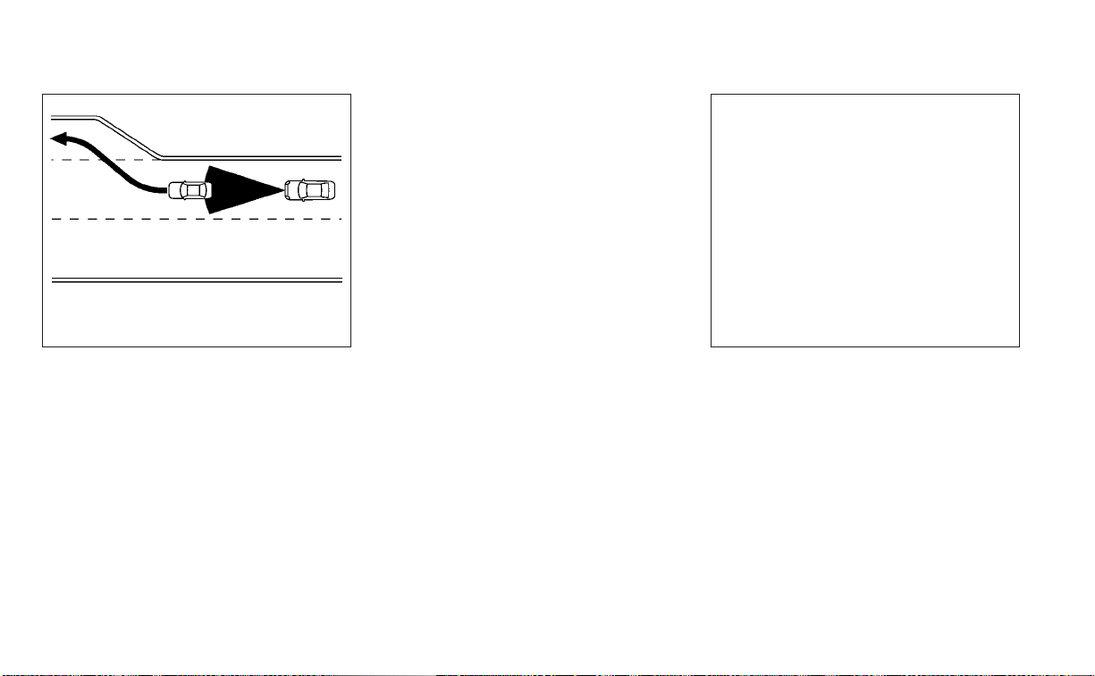
When driving on the freeway at a set speed
and approaching a slower traveling vehicle
ahead, the ICC system adjusts the speed to
maintain the distance, selected by the
driver, from the vehicle ahead. If the vehicle
ahead changes lanes or exits the freeway,
the ICC system accelerates and maintains
the speed up to the set speed. Pay atten-
tion to the driving operation to maintain
control of the vehicle as it accelerates to
the set speed.
The vehicle may not maintain the set
speed on winding or hilly roads. If this oc-
curs, you will have to manually control the
vehicle speed.
Normally when controlling the distance to
a vehicle ahead, the system automatically
accelerates or decelerates your vehicle ac-
cording to the speed of the vehicle ahead.
Depress the accelerator to properly accel-
erate your vehicle when acceleration is re-
quired for a lane change. Depress the brake
pedal when deceleration is required to
maintain a safe distance to the vehicle
ahead due to sudden braking or if a vehicle
cuts in. Always stay alert when using the
ICC system.
No vehicle detected ahead
The driver sets the desired vehicle speed
based on the road conditions. The ICC sys-
tem maintains the set vehicle speed, simi-
lar to standard cruise control, as long as no
vehicle is detected in the lane ahead. The
ICC system displays the set speed.
SSD0254 LSD3316
System set display with no vehicle
detected ahead
5-84 Starting and driving

Vehicle detected ahead
When a vehicle is detected in the lane
ahead, the ICC system decelerates the ve-
hicle by controlling the throttle and apply-
ing the brakes to match the speed of a
slower vehicle ahead. The ICC system then
controls the vehicle speed based on the
speed of the vehicle ahead to maintain the
driver selected distance.
NOTE:
• The stop lights of the vehicle come on
when braking is performed by the ICC
system.
• When the brake is applied by the sys-
tem, a noise may be heard. This is not a
malfunction.
When the ICC system detects a vehicle
ahead, the vehicle ahead detection indica-
tor and the speed control status indicator
(distance control mode) illuminates (solid
green
).
Vehicle ahead stops
When the vehicle ahead decelerates to
stop, your vehicle decelerates to a stand-
still. Once your vehicle stops, the ICC sys-
tem automatically applies the brakes to
keep the vehicle stopped. When your ve-
hicle is at a standstill, the “(RES+) Press to
start” message is displayed on the vehicle
information display.
NOTE:
When your vehicle stops for less than 3
seconds, your vehicle will automatically
follow the vehicle as it accelerates from a
stop.
Vehicle ahead accelerates
When your vehicle is stopped and the ve-
hicle ahead begins to accelerate, push the
RES+ switch or lightly depress the accelera-
tor pedal. The ICC system starts to follow
the vehicle ahead.
Vehicle ahead not detected
When a vehicle is no longer detected
ahead, the ICC system gradually acceler-
ates your vehicle to resume the previously
set vehicle speed. The ICC system then
maintains the set speed.
When a vehicle is no longer detected, the
vehicle ahead detection indicator turns off
and speed control status indicator (main-
tain speed control mode) illuminates
(green outline
).
The ICC system gradually accelerates to
the set speed, but you can depress the
accelerator pedal to quickly accelerate.
When a vehicle is no longer detected and
your vehicle is traveling under approxi-
mately 15 mph (24 km/h), the ICC system
automatically cancels.
LSD3233
System set display with vehicle ahead
Starting and driving 5-85

When passing another vehicle, the set
speed indicator
O
A
flashes when the ve-
hicle speed exceeds the set speed. The ve-
hicle ahead detection indicator turns off
when the area ahead of the vehicle is open.
When the pedal is released, the vehicle re-
turns to the previously set speed. Even
though your vehicle speed is set in the ICC
system, you can depress the accelerator
pedal when it is necessary to accelerate
your vehicle rapidly.
Cut-in detection
If a vehicle moves into your traveling lane
near your vehicle, the ICC system may in-
form the driver by flashing the vehicle
ahead detection indicator.
Approach warning
If your vehicle comes closer to the vehicle
ahead due to rapid deceleration of that ve-
hicle or if another vehicle cuts in, the sys-
tem warns the driver with the chime and
ICC system display. Decelerate by depress-
ing the brake pedal to maintain a safe ve-
hicle distance if:
• The chime sounds.
• The vehicle ahead detection indicator
and set distance indicator blink.
• You judge it necessary to maintain a safe
distance.
The warning chime may not sound in
some cases when there is a short distance
between vehicles. Some examples are:
• When the vehicles are traveling at the
same speed and the distance between
vehicles is not changing.
• When the vehicle ahead is traveling faster
and the distance between vehicles is
increasing.
• When a vehicle cuts in near your vehicle.
The warning chime will not sound when:
• Your vehicle approaches other vehicles
that are parked or moving slowly.
• The accelerator pedal is depressed, over-
riding the system.
NOTE:
The approach warning chime may sound
and the system display may flash when
the radar sensor detects objects on the
side of the vehicle or on the side of the
road. This may cause the ICC system to
decelerate or accelerate the vehicle. The
radar sensor may detect these objects
when the vehicle is driven on winding,
narrow, or hilly roads or when the vehicle
is entering or exiting a curve. In these
cases, you will have to manually control
the proper distance ahead of your
vehicle.
LSD3234
5-86 Starting and driving

Also, the sensor sensitivity can be af-
fected by vehicle operation (steering
maneuver or driving position in the lane)
or traffic or vehicle conditions (for ex-
ample, if a vehicle is being driven with
some damage).
Acceleration when passing
When the ICC system is engaged above 43
mph and following a slower vehicle (below
ICC set speed), and the turn signal is acti-
vated to the left, the ICC system will auto-
matically start to accelerate the vehicle to
help initiate passing on the left and will
begin to reduce the distance to vehicle di-
rectly ahead. Only the left side turn signal
operates this feature. As the driver steers
the vehicle and moves into the passing
lane, if no vehicle is detected ahead the ICC
system will continue to accelerate to the
ICC system set speed. If another vehicle is
detected ahead, then the vehicle will accel-
erate up to the following speed of that ve-
hicle. If the vehicle is not steered into the
left lane to pass, the acceleration will stop
after a short time and regain the set follow-
ing distance. Acceleration can be stopped
at any point by depressing the brake pedal
or the CANCEL switch on the steering
wheel.
WARNING
In order to reduce the risk of a collision
that may result in serious injury or
death, please be aware of the following:
• This function is only activated with
the left turn signal and will briefly ac-
celerate the vehicle even if a lane
change is not initiated. This can in-
clude non-passing situations such as
left side exits.
• Ensure that when passing another
vehicle, the adjacent lane is clear be-
fore initiating the pass. Sudden
changes in traffic may occur while
passing- always manually steer or
brake as needed- never solely rely on
the system.
ICC system limitations
WARNING
Listed below are the system limitations
for the ICC system. Failure to operate
the vehicle in accordance with these
system limitations could result in seri-
ous injury or death:
• The ICC system is primarily intended
for use on straight, dry, open roads
with light traffic. It is not advisable to
use the ICC system in city traffic or
congested areas.
• The ICC system will not adapt auto-
matically to road conditions. This
system should be used in evenly
flowing traffic. Do not use the system
on roads with sharp curves or on icy
roads, in heavy rain or in fog.
Starting and driving 5-87

• As there is a performance limit to the
distance control function, never rely
solely on the ICC system. This system
does not correct careless, inattentive
or absentminded driving or over-
come poor visibility in rain, fog, or
other bad weather. Decelerate the
vehicle speed by depressing the
brake pedal, depending on the dis-
tance to the vehicle ahead and the
surrounding circumstances in order
to maintain a safe distance between
vehicles.
• When the ICC system automatically
brings the car to a stop, your vehicle
can automatically accelerate if the
vehicle is stopped for less than ap-
proximately 3 seconds. Be prepared
to stop your vehicle if necessary.
• Always pay attention to the opera-
tion of the vehicle and be ready to
manually control the proper follow-
ing distance. The ICC system may not
be able to maintain the selected dis-
tance between vehicles (following
distance) or selected vehicle speed
under some circumstances.
• The system may not detect the ve-
hicle in front of you in certain road or
weather conditions. To avoid acci-
dents, never use the ICC system un-
der the following conditions:
– On roads with heavy, high-speed
traffic or sharp curves
– On slipper y road surfaces such as
on ice or snow, etc.
– During bad weather (rain, fog,
snow, etc.)
– When rain, snow or dirt adhere to
the bumper around the distance
sensor
– On steep downhill roads (the ve-
hicle may go beyond the set ve-
hicle speed and frequent braking
may result in overheating the
brakes)
– On repeated uphill and downhill
roads
– When traffic conditions make it
difficult to keep a proper distance
between vehicles because of fre-
quent acceleration or
deceleration
– Inter ference by other radar
sources.
• Do not use the ICC system if you are
towing a trailer. The system may not
detect a vehicle ahead.
• In some road or traffic conditions, a
vehicle or object can unexpectedly
come into the sensor detection zone
and cause automatic braking. Al-
ways stay alert and avoid using the
ICC system where not recommended
in this warning section.
The ICC system will not detect the following
objects:
• Stationary or slow moving vehicles
• Pedestrians or objects in the roadway
• Oncoming vehicles in the same lane
• Motorcycles traveling offset in the travel
lane
The following are some conditions in which
the radar sensor cannot properly detect a
vehicle ahead and the system may not op-
erate properly:
• When the sensor detection is reduced
(conditions such as rain, snow, fog, dust
storms, sandstorms, and road spray from
other vehicles)
• Driving on a steep downhill slope or roads
with sharp curves
5-88 Starting and driving

• Driving on a bumpy road surface, such as
an uneven dirt road
• If dirt, ice, snow or other material is cover-
ing the radar sensor area
• A complicated-shaped vehicle such as a
car carrier trailer or flatbed truck/trailer is
near the vehicle ahead.
• Interference by other radar sources
• When your vehicle is towing a trailer, etc.
• When excessively heavy baggage is
loaded in the rear seat or cargo area of
your vehicle.
The ICC system is designed to automati-
cally check the radar sensor’s operation
within the limitations of the system.
The detection zone of the radar sensor is
limited. A vehicle ahead must be in the de-
tection zone for the ICC system to maintain
the selected distance from the vehicle
ahead. A vehicle ahead may move outside
of the detection zone due to its position
within the same lane of travel. Motorcycles
may not be detected in the same lane
ahead if they are traveling offset from the
center line of the lane. A vehicle that is en-
tering the lane ahead may not be detected
until the vehicle has completely moved into
the lane.
If this occurs, the ICC system may warn you
by blinking the system indicator and
sounding the chime. The driver may have
to manually control the proper distance
away from the vehicle traveling ahead.
The ICC system (with ProPILOT Assist) uses
a multi-sensing front camera. The follow-
ing are some conditions in which the cam-
era may not properly detect a vehicle and
detection of a vehicle ahead may be de-
layed:
• Poor visibility (conditions such as rain,
snow, fog, dust storms, sandstorms, and
road spray from other vehicles)
• The camera area of the windshield is
fogged up or covered with dirt, water
drops, ice, snow, etc.
• Strong light (for example, sunlight or high
beams from oncoming vehicles) enters
the front camera
• A sudden change in brightness occurs
(for example, when the vehicle enters or
exits a tunnel or shaded area or lightning
flashes)
Starting and driving 5-89
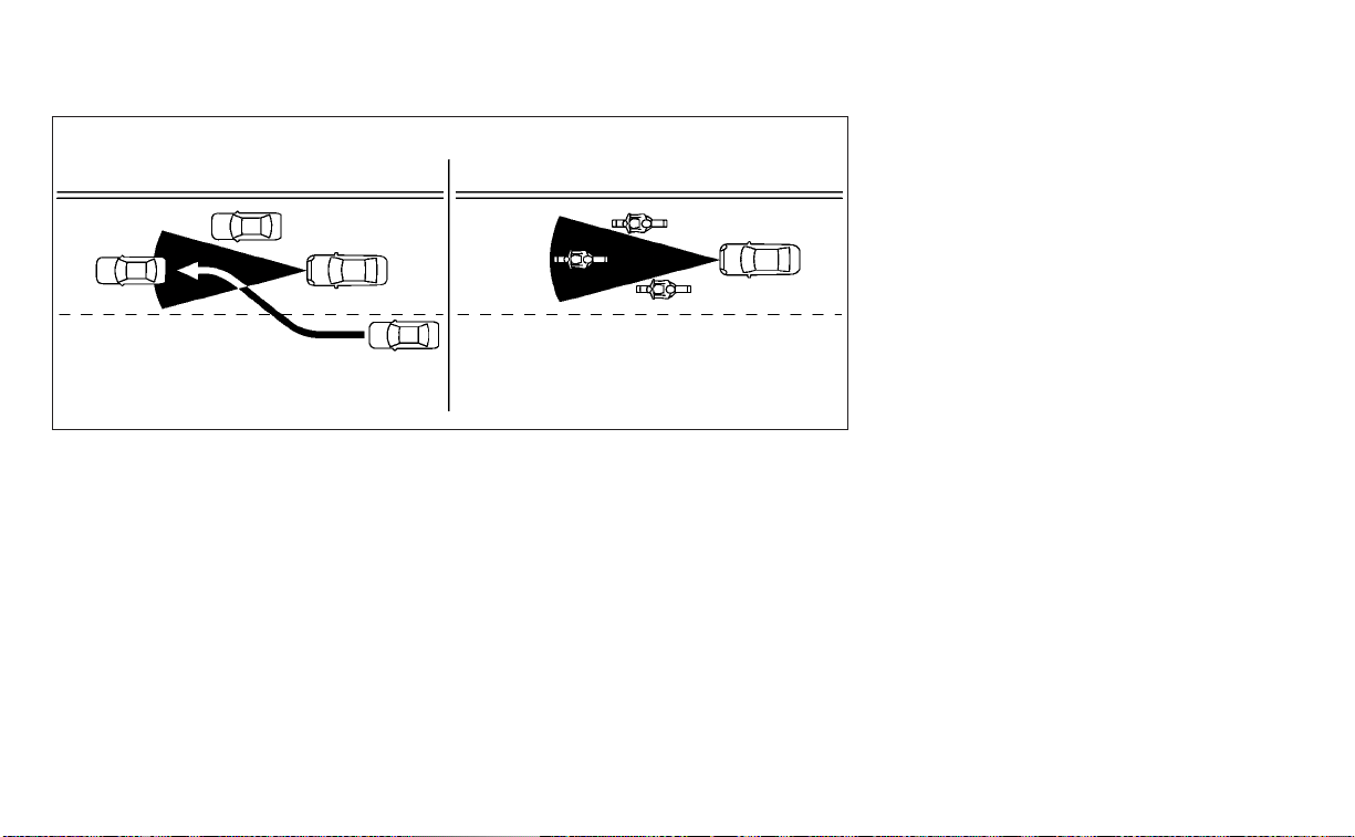
SSD0252
5-90 Starting and driving
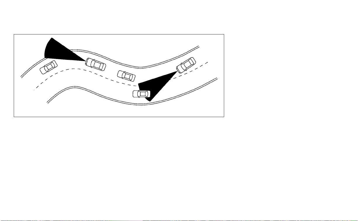
When driving on some roads, such as wind-
ing, hilly, curved, narrow roads, or roads
which are under construction, the radar
sensor may detect vehicles in a different
lane, or may temporarily not detect a ve-
hicle traveling ahead. This may cause the
radar system to decelerate or accelerate
the vehicle.
The detection of vehicles may also be af-
fected by vehicle operation (steering ma-
neuver or traveling position in the lane, etc.)
or vehicle condition.
If this occurs, the ICC system may warn you
by blinking the system indicator and sound-
ing the chime unexpectedly. You will have to
manually control the proper distance away
from the vehicle traveling ahead.
System Temporarily Unavailable
The following are conditions in which the
ICC system may be temporarily unavail-
able. In these instances, the ICC system
may not cancel and may not be able to
maintain the selected following distance
from the vehicle ahead.
Condition A
Under the following conditions, the ICC sys-
tem is automatically canceled. A chime will
sound and the system will not be able to be
set:
• Any door is open.
• The driver’s seat belt is not fastened.
• The vehicle ahead is not detected and
your vehicle is traveling below the speed
of 15 mph (24 km/h).
• Your vehicle has been stopped by the ICC
system for approximately 3 minutes or
longer.
• The shift lever is not in the D (Drive) posi-
tion or manual shift mode.
• The electronic parking brake is applied.
• The VDC system is turned off.
• The AEB with Pedestrian Detection ap-
plies harder braking.
• VDC (including the traction control sys-
tem) operates.
• A wheel slips.
• When the radar signal is temporarily
interrupted.
SSD0253
Starting and driving 5-91

Action to take:
When the conditions listed above are no
longer present, turn the system off using
the ProPILOT Assist switch. Turn the ProPI-
LOT Assist system back on to use the
system.
NOTE:
When the ICC system is canceled un-
der the following conditions at a
standstill, the electronic parking brake
is automatically activated:
• Any door is open.
• The driver’s seat belt is not fastened.
• Your vehicle has been stopped by the
ICC system for approximately 3 min-
utes or longer.
• The shift lever is not in the D (Drive)
position or manual shift mode.
• The VDC system is turned off.
• When distance measurement be-
comes impaired due to adhesion of dirt
or obstruction to the sensor.
• When the radar signal is temporarily
interrupted.
Condition B
When there is inclement weather (rain, fog,
snow, etc.) blocking the front radar sensor,
the ICC system will automatically be can-
celed, the chime will sound and the “For-
ward Driving Aids Temporarily Disabled
Front Sensor Blocked See Owner’s Manual”
warning message will appear in the vehicle
information display.
Action to take:
When the conditions listed above are no
longer present, the warning message will
no longer be available in the vehicle infor-
mation display and the system will operate
normally. If the “Forward Driving Aids Tem-
porarily Disabled Front Sensor Blocked See
Owner’s Manual” warning message contin-
ues to be displayed, have the system
checked. It is recommended that you visit a
NISSAN dealer for this service.
Condition C
When the radar sensor of the front bumper
is covered with dirt or is obstructed, the ICC
system will automatically be canceled.
The chime will sound and the “Forward
Driving Aids Temporarily Disabled Front
Sensor Blocked See Owner’s Manual”
warning message will appear in the vehicle
information display.
Action to take:
If the warning message appears, stop the
vehicle in a safe place, place the shift lever
in the P (Park) position, and turn the engine
off. When the radar signal is temporarily
interrupted, clean the sensor area of the
front bumper and restart the engine. If the
“Forward Driving Aids Temporarily Disabled
Front Sensor Blocked See Owner’s Manual”
warning message continues to be dis-
played, have the system checked. It is rec-
ommended that you visit a NISSAN dealer
for this service.
Condition D
When driving on roads with limited road
structures or buildings (for example, long
bridges, deserts, snow fields, driving next to
long walls), the system may illuminate the
system warning light and display the “For-
ward Driving Aids Temporarily Disabled
Front Sensor Blocked See Owner’s Manual”
warning message.
Action to take:
When the above driving conditions no lon-
ger exist, turn the system back on.
5-92 Starting and driving

ICC system malfunction
If the ICC system malfunctions, it will be
turned off automatically, a chime will
sound, and the speed control status warn-
ing (orange) will illuminate.
Action to take:
If the warning light comes on, stop the ve-
hicle in a safe place. Turn the engine off,
restart the engine and set the ICC system
again. If it is not possible to set the ICC
system or the indicator stays on, it may be
a malfunction. Although the normal driving
can be continued, the ICC system should
be inspected. It is recommended that you
visit a NISSAN dealer for this service.
NOTE:
If the ICC system is temporarily unavail-
able, the conventional cruise control
mode may still be used. For additional
information, please see “Conventional
(fixed speed) cruise control mode”
(P. 5-100).
ICC sensor maintenance
The radar sensor is located on the front of
the vehicle.
To keep the ICC system operating properly,
be sure to observe the following:
• Always keep the sensor area of the front
bumper/emblem clean.
• Do not strike or damage the areas
around the sensor.
• Do not attach a sticker (including trans-
parent material) or install an accessory
near the sensor. This could cause failure
or malfunction.
• Do not attach metallic objects near the
sensor area (brush guard, etc.). This could
cause failure or malfunction.
• Do not alter, remove, or paint the front
bumper.
Before customizing or restoring the front
bumper, it is recommended that you visit a
NISSAN dealer.
The camera sensor is located above the
inside mirror.
To keep the proper operation of the sys-
tems and prevent a system malfunction,
be sure to observe the following:
• Always keep the windshield clean.
• Do not attach a sticker (including trans-
parent material) or install an accessory
near the camera unit.
• Do not place reflective materials, such as
white paper or a mirror, on the instru-
ment panel. The reflection of sunlight
may adversely affect the camera unit’s
capability of detecting the lane markers.
• Do not strike or damage the areas
around the camera unit. Do not touch the
camera lens or remove the screw located
on the camera unit.
If the camera unit is damaged due to an
accident, it is recommended that you visit a
NISSAN dealer.
LSD3916
Starting and driving 5-93

STEERING ASSIST
WARNING
Failure to follow the warnings and in-
structions for proper use of the Steer-
ing Assist could result in serious injury
or death.
• The Steering Assist is not a replace-
ment for proper driving procedures
and is not designed to correct care-
less, inattentive or absent-minded
driving. The Steering Assist will not
always steer the vehicle to keep it in
the lane. It is not designed to prevent
loss of control. It is the driver’s re-
sponsibility to stay alert, drive safely,
keep the vehicle in the traveling lane,
and be in control of the vehicle at all
times.
• As there is a performance limit to the
Steering Assist’s capability, never
rely solely on the system. The Steer-
ing Assist does not function in all
driving, traffic, weather, and road
conditions. Always drive safely, pay
attention to the operation of the ve-
hicle, and manually control your ve-
hicle appropriately.
• The Steering Assist is intended for
use on well-developed freeways or
highways with gentle (moderate)
curves. To avoid risk of an accident,
do not use this system on local or
non-highway roads.
• The Steering Assist only steers the
vehicle to maintain its position in the
center of a lane. The vehicle will not
steer to avoid objects in the road in
front of the vehicle or to avoid a ve-
hicle moving into your lane.
• It is the driver’s responsibility to stay
alert, drive safely, keep the vehicle in
the traveling lane, and be in control of
the vehicle at all times. Never take
your hands off the steering wheel
when driving. Always keep your
hands on the steering wheel and
drive your vehicle safely.
• Always drive carefully and atten-
tively when using the Steering Assist.
Read and understand the Owner’s
Manual thoroughly before using the
Steering Assist. To avoid serious in-
jury or death, do not rely on the sys-
tem to prevent accidents or to con-
trol the vehicle’s speed in emergency
situations. Do not use the Steering
Assist except in appropriate road and
traffic conditions.
Steering Assist operation
The Steering Assist controls the steering
system to help keep your vehicle near the
center of the lane when driving. The Steer-
ing Assist is combined with the Intelligent
Cruise Control (ICC) system. For additional
information, see “Intelligent Cruise Control
(ICC) (for vehicles with ProPILOT Assist)”
(P. 5-82).
The Steering Assist can be activated when
the following conditions are met:
• The ICC system is activated.
• Lane markers on both sides are clearly
detected.
• A vehicle ahead is detected (when the
vehicle is driven at speeds under 37 mph
[60 km/h]).
5-94 Starting and driving

• The driver grips the steering wheel.
• The vehicle is driven at the center of the
lane.
• The turn signals are not operated.
• The windshield wiper is not operated in
the high (HI) speed operation (the Steer-
ing Assist function is disabled after the
wiper operates for approximately 10
seconds).
Steering Assist display and
indicators
䊊
1
Steering Assist status indicator/
warning
Displays the status of the Steering Assist by
the color of the indicator/warning
• Steering Assist indicator (gray): Steering
Assist standby
• Steering Assist indicator (green): Steering
Assist active
• Steering Assist indicator (yellow): Steering
Assist malfunction
䊊
2
Steering Assist indicator
Indicates the status of the Steering Assist
by the color of the indicator
• Steering Assist indicator (gray): Steering
Assist standby
• Steering Assist indicator (green): Steering
Assist active
䊊
3
Lane marker indicator
Indicates whether the system detects the
lane marker
• Lane marker indicator (gray): Lane mark-
ers not detected
• Lane marker indicator (green): Lane
markers detected
• Lane marker indicator (yellow): Lane de-
parture is detected
When the Steering Assist is in operation,
the Steering Assist status indicator
O
1
, the
Steering Assist indicator
O
2
, and the lane
marker indicator
O
3
on the vehicle infor-
mation display turn green. A chime sounds
when the Steering Assist initially activates.
When the Steering Assist deactivates, the
Steering Assist status indicator
O
1
, the
Steering Assist indicator
O
2
, and the lane
marker indicator
O
3
on the vehicle infor-
mation display turn gray and a chime
sounds twice.
LSD3235
Starting and driving 5-95

Intelligent Lane Intervention (I-LI)
When a curve or strong cross wind exceeds
the capabilities of the Steering Assist and
your vehicle approaches either the left or
the right side of the traveling lane, the I-LI
indicator (orange) on the instrument panel
flashes to alert the driver. Then, the I-LI sys-
tem automatically applies the brakes for a
short period of time to help assist the
driver to return the vehicle to the center of
the traveling lane. This action is in addition
to any Steering Assist actions.
Hands on detection
When the Steering Assist is activated, it
monitors the driver’s steering wheel
operation.
LSD3236
5-96 Starting and driving

If the steering wheel is not operated or the
driver takes his/her hands off the steering
wheel for a period of time, the warning
O
1
appears in the vehicle information display.
If the driver does not operate the steering
wheel after the warning has been dis-
played, an audible alert sounds and the
warning flashes in the vehicle information
display, followed by a quick brake applica-
tion to request the driver to take control of
the vehicle again.
If the driver still does not respond, the Pro-
PILOT Assist turns on the hazard flasher
and slows the vehicle to a complete stop.
The driver can cancel the deceleration at
any time by steering, braking, accelerating,
or operating the ProPILOT Assist switch.
WARNING
Steering Assist is not a system for
hands-free driving. Always keep your
hands on the steering wheel and drive
your vehicle safely. Failure to do so
could cause a collision resulting in seri-
ous personal injury or death.
NOTE:
If the driver lightly touches (instead of
firmly grips) the steering wheel, the
steering torque sensor may not detect
the driver’s hand(s) on the wheel and a
sequence of warnings may occur. When
the driver holds and operates the steer-
ing wheel again, the warnings turn off.
Steering Assist limitations
WARNING
• In the following situations, the cam-
era may not detect lane markers cor-
rectly or may detect lane markers in-
correctly and the Steering Assist may
not operate properly:
– When driving on roads where
there are multiple parallel lane
markers, lane markers that are
faded or not painted clearly, non-
standard lane markers, or lane
markers covered with water, dirt,
snow, etc.
– When driving on roads with dis-
continued lane markers
– When driving on roads with a wid-
ening or narrowing lane width
– When driving on roads where
there are multiple lanes or unclear
lane markers due to road
construction
– When driving on roads where
there are sharply contrasting ob-
jects, such as shadows, snow, wa-
ter, wheel ruts, seams, or lines re-
maining after road repairs (the
Steering Assist could detect these
items as lane markers)
– When driving on roads where the
traveling lane merges or
separates
• Do not use the Steering Assist under
the following conditions because the
system may not properly detect lane
markers. Doing so could cause a loss
of vehicle control and result in an ac-
cident.
– During bad weather (rain, fog,
snow, dust, etc.)
– When rain, snow, sand, etc., is
thrown up by the wheels of other
vehicles
– When dirt, oil, ice, snow, water, or
another object adheres to the
camera unit
Starting and driving 5-97

– When the lens of the camera unit
is foggy
– When strong light (for example,
sunlight or high beams from on-
coming vehicles) shines on the
camera
– When the headlights are not
bright due to dirt on the lens or
the headlights are off in tunnels or
darkness
– When a sudden change in bright-
ness occurs (for example, when
the vehicle enters or exits a tunnel
or is under a bridge)
– When driving on roads where the
traveling lane merges or sepa-
rates or where there are tempo-
rary lane markers because of road
construction
– When there is a lane closure due to
road repairs
– When driving on a bumpy road
sur face, such as an uneven dirt
road
– When driving on sharp curves or
winding roads
– When driving on repeated uphill
and downhill roads
• Do not use the Steering Assist under
the following conditions because the
system will not operate properly:
– When driving with a tire that is not
within normal tire conditions (for
example, tire wear, abnormal tire
pressure, installation of a spare
tire, tire chains, nonstandard
wheels)
– When the vehicle is equipped with
non-original brake or suspension
parts
– When an object such as a sticker
or cargo obstructs the camera
– When excessively heavy baggage
is loaded in the rear seat or lug-
gage area of your vehicle
– When the vehicle load capacity is
exceeded
– When towing a trailer or other
vehicle
• Excessive noise will interfere with the
warning chime sound, and the beep
may not be heard.
• For the ProPILOT Assist system to op-
erate properly, the windshield in
front of the camera must be clean.
Replace worn wiper blades. The cor-
rect size wiper blades must be used
to help make sure the windshield is
kept clean. Only use Genuine NISSAN
wiper blades, or equivalent wiper
blades, that are specifically designed
for use on your vehicle model and
model year. It is recommended that
you visit a NISSAN dealer for the cor-
rect parts for your vehicle.
Steering Assist temporary
standby
Automatic standby due to driving
operation:
When the driver activates the turn signal,
the Steering Assist is temporarily placed in
a standby mode. (The Steering Assist re-
starts automatically when the operating
conditions are met again.)
Automatic standby:
In the following cases, a warning message
is displayed along with the chime, and the
Steering Assist is placed in a temporary
5-98 Starting and driving

standby mode. (The Steering Assist re-
starts automatically when the operating
conditions are met again.)
• When lane markers on both sides are no
longer detected
•
When a vehicle ahead is no longer detected
under approximately 37 mph (60 km/h)
Steering Assist cancel
Under the following conditions, the Steer-
ing Assist cancels, and the Steering Assist
status indicator and the Steering Assist in-
dicator turn off:
• When unusual lane markers appear in
the traveling lane or when the lane
marker cannot be correctly detected for
some time due to certain conditions (for
example, a snow rut, the reflection of light
on a rainy day, the presence of several
unclear lane markers)
•
When the windshield wiper operates in the
high (HI) speed operation (the Steering As-
sist is disabled when the wiper operates for
more than approximately 10 seconds)
Action to take:
Turn the ICC system off using the CANCEL
switch. When the conditions listed above
are no longer present, turn the ICC system
on again.
Steering Assist malfunction
When the system malfunctions, it turns off
automatically. The Steering Assist status
warning illuminates (orange). A chime may
sound depending on the situation.
Action to take:
Stop the vehicle in a safe location, place the
vehicle in the P (Park) position, turn the en-
gine off, restart the engine, resume driving,
and set the Intelligent Cruise Control sys-
tem again. If the warning (orange) contin-
ues to illuminate, the Steering Assist is mal-
functioning. Although the vehicle is still
drivable under normal conditions, have the
system checked. It is recommended that
you visit a NISSAN dealer for this service.
Steering Assist maintenance
The camera sensor is located above the
inside mirror.
To keep the proper operation of the system
and prevent a system malfunction, be sure
to observe the following:
• Always keep the windshield clean.
• Do not attach a sticker (including trans-
parent material) or install an accessory
near the camera unit.
• Do not place reflective materials, such as
white paper or a mirror, on the instru-
ment panel. The reflection of sunlight
may adversely affect the camera unit’s
capability of detecting the lane markers.
• Do not strike or damage the areas
around the camera unit. Do not touch the
camera lens or remove the screw located
on the camera unit.
If the camera unit is damaged due to an
accident, it is recommended that you visit a
NISSAN dealer.
Radio frequency statement
For USA
FCC ID OAYARS4B
This device complies with Part 15 of the FCC
Rules. Operation is subject to the following
two conditions:
1. This device may not cause harmful inter-
ference, and
2. This device must accept any interfer-
ence received, including interference
that may cause undesired operation.
Starting and driving 5-99

FCC Warning
Changes or modifications not expressly
approved by the party responsible for
compliance could void the user’s authority
to operate the equipment.
For Canada
Model: ARS4–B
IC: 4135A-ARS4B
FCC ID: OAYARS4B
This device complies with Part 15 of the FCC
Rules and with Industry Canada licence-
exempt RSS standard(s). Operation is sub-
ject to the following two conditions:
1. This device may not cause interference,
and
2. This device must accept any interfer-
ence received, including interference
that may cause undesired operation of
the device.
Le présent appareil est conforme aux CNR
d'Industrie Canada applicables aux appar-
eils radio exempts de licence. L'exploitation
est autorisée aux deux conditions
suivantes:
1. L'appareil ne doit pas produire de brouil-
lage, et
2. L'utilisateur de l'appareil doit accepter
tout brouillage radioélectrique subi,
même si le brouillage est susceptible
d'en compromettre le fonctionnement.
Radio frequency radiation exposure
information:
This equipment complies with FCC and IC
radiation exposure limits set forth for an
uncontrolled environment.
This equipment should be installed and
operated with minimum distance of 30 cm
between the radiator and your body.
This transmitter must not be co-located or
operating in conjunction with any other an-
tenna or transmitter.
Cet équipement est conforme aux limites
d'exposition aux rayonnements IC établies
pour un environnement non contrôlé.
Cet équipement doit être installé et utilisé
avec un minimum de 30 cm de distance
entre la source de rayonnement et votre
corps.
FCC Notice
Changes or modifications not expressly
approved by the party responsible for
compliance could void the user’s authority
to operate the equipment.
CONVENTIONAL (fixed speed)
CRUISE CONTROL MODE
NOTE:
ProPILOT Assist provides no approach
warnings, automatic braking, or steering
assist in the conventional (fixed speed)
cruise control mode.
This mode allows driving at a speed be-
tween 25 to 90 mph (40 to 144 km/h) with-
out keeping your foot on the accelerator
pedal.
WARNING
• In the conventional (fixed speed)
cruise control mode, a warning
chime does not sound to warn you if
you are too close to the vehicle
ahead, as neither the presence of the
vehicle ahead nor the vehicle-to-
vehicle distance is detected.
• Pay special attention to the distance
between your vehicle and the vehicle
ahead of you or a collision could
occur.
• Always confirm the setting in the ICC
system display.
5-100 Starting and driving

• Do not use the conventional (fixed
speed) cruise control mode when
driving under the following condi-
tions:
– When it is not possible to keep the
vehicle at a set speed
– In heavy traffic or in traffic that
varies in speed
– On winding or hilly roads
– On slippery roads (rain, snow, ice,
etc.)
– In very windy areas
• Doing so could cause a loss of vehicle
control and result in an accident.
Conventional (fixed speed) cruise
control switches
䊊
1
RES+ switch:
Resumes set speed or increases speed
incrementally
䊊
2
CANCEL switch:
Deactivates the system without eras-
ing the set speed
䊊
3
ProPILOT Assist switch:
Turns the ProPILOT Assist system on or
off
䊊
4
SET- switch:
Sets desired cruise speed or reduces
speed incrementally
LSD3120
Starting and driving 5-101

Conventional (fixed speed) cruise
control mode display and
indicators
The display is located in the vehicle infor-
mation display.
1. Set vehicle speed indicator:
This indicator indicates the set vehicle
speed. For Canadian models, the speed
is displayed in km/h.
2. Cruise indicator:
This indicator indicates the condition of
the ICC system depending on a color.
• Cruise control ON indicator (gray): Indi-
cates that the ProPILOT Assist switch is
on
• Cruise control SET indicator (green): Indi-
cates that the cruising speed is set
• Cruise control warning (yellow): Indicates
that there is a malfunction in the ICC
system
Operating conventional (fixed
speed) cruise control mode
To turn on the conventional (fixed speed)
cruise control mode, push and hold the
ProPILOT Assist switch
O
A
for longer than
about 1.5 seconds.
When pushing the ProPILOT Assist switch
on, the conventional (fixed speed) cruise
control mode display and indicators
O
B
are
displayed in the vehicle information dis-
play. After you hold the ProPILOT Assist
switch on for longer than about 1.5 sec-
onds, the ICC system display turns off. The
cruise indicator appears. You can now set
LSD3283 LSD3284
5-102 Starting and driving

your desired cruising speed. Pushing the
ProPILOT Assist switch again will turn the
system completely off. When the ignition
switch is placed in the OFF position, the
system is also automatically turned off.
To use the ICC system again, quickly push
and release the ProPILOT Assist switch
(vehicle-to vehicle distance control mode)
or push and hold it (conventional cruise
control mode) again to turn it on.
CAUTION
To avoid accidentally engaging cruise
control, make sure to turn the ProPILOT
Assist switch off when not using the ICC
system.
To set cruising speed, accelerate your ve-
hicle to the desired speed, push the SET-
O
C
switch and release it. (The color of the
cruise indicator changes to green and set
vehicle speed indicator comes on.) Take
your foot off the accelerator pedal. Your
vehicle will maintain the set speed.
• To pass another vehicle, depress the ac-
celerator pedal. When you release the
pedal, the vehicle will return to the previ-
ously set speed.
• The vehicle may not maintain the set
speed when going up or down steep hills.
If this happens, manually maintain ve-
hicle speed.
To cancel the preset speed, use any of the
following methods:
1. Push the CANCEL switch. The vehicle
speed indicator will turn off.
2. Tap the brake pedal. The vehicle speed
indicator will turn off.
3. Turn the ProPILOT Assist switch off. Both
the cruise indicator and vehicle speed
indicator will turn off.
To reset at a faster cruising speed, use one
of the following three methods:
1. Depress the accelerator pedal. When the
vehicle attains the desired speed, push
and release the SET- switch.
2. Push and hold the RES+ switch. When
the vehicle attains the desired speed,
release the switch.
3. Push, then quickly release the RES+
switch. Each time you do this, the set
speed will increase by about 1 mph (1.6
km/h).
To reset at a slower cruising speed, use one
of the following three methods:
1. Lightly tap the brake pedal. When the
vehicle attains the desired speed, push
the SET- switch and release it.
LSD3285
Starting and driving 5-103

2. Push and hold the SET- switch. Release
the switch when the vehicle slows down
to the desired speed.
3. Push, then quickly release the SET-
switch. Each time you do this, the set
speed will decrease by about 1 mph (1.6
km/h).
To resume the preset speed, push and re-
lease the RES+ switch. The vehicle will re-
sume the last set cruising speed when the
vehicle speed is over 25 mph (40 km/h).
WARNING
Failure to follow the warnings and in-
structions for proper use of the RAB
system could result in serious injury or
death.
• The RAB system is a supplemental
aid to the driver. It is not a replace-
ment for proper driving procedures.
Always use the side and rear mirrors
and turn and look in the direction you
will move before and while backing
up. Never rely solely on the RAB sys-
tem. It is the driver’s responsibility to
stay alert, drive safely, and be in con-
trol of the vehicle at all times.
• There is a limitation to the RAB sys-
tem capability. The RAB system is not
effective in all situations.
• Inclement weather or ultrasonic
sources such as an automatic car
wash, a truck’s compressed-air
brakes or a pneumatic drill may af-
fect the function of the system; this
may include reduced performance or
a false activation.
The RAB system can assist the driver when
the vehicle is backing up and approaching
objects directly behind the vehicle.
The RAB system detects obstacles behind
the vehicle using the parking sensors
O
1
located on the rear bumper.
NOTE:
You can temporarily cancel the sonar
function in the vehicle, but the RAB sys-
tem will continue to operate. For addi-
tional information, please see “Rear So-
nar System (RSS)” (P. 5-154).
LSD3241
REAR AUTOMATIC BRAKING (RAB) (if
so equipped)
5-104 Starting and driving

RAB SYSTEM OPERATION
䊊
1
RAB system warning light and RAB sys-
tem warning indicator
䊊
2
Steering-wheel-mounted controls (left
side)
䊊
3
Center display
When the shift lever is in the R (Reverse)
position and the vehicle speed is less than
approximately 9 mph (15 km/h), the RAB
system operates.
If a risk of a collision with an obstacle is
detected when your vehicle is backing up,
the RAB system warning indicator will flash
in the vehicle information display, a red
frame will appear in the center display (for
vehicles with the Intelligent Around View
Monitor system), and the system will chime
three times. The system will then auto-
matically apply the brakes. After the auto-
matic brake application, the driver must
depress the brake pedal to maintain brake
pressure.
LSD3279
For vehicles with the 7 inch (18 cm) display
Starting and driving 5-105

NOTE:
• The brake lights of the vehicle come on
when braking is performed by the RAB
system.
• When the brakes operate, a noise may
be heard. This is not a malfunction.
LSD3909
For vehicles with the 5 inch (13 cm) display
5-106 Starting and driving

TURNING THE RAB SYSTEM
ON/OFF
Perform the following steps to turn the RAB
system ON or OFF.
For vehicles with the 7 inch (18 cm)
display.
1. Press the
button until “Settings” dis-
plays in the vehicle information display.
Use the
button to select “Driver As-
sistance.” Then press the OK button.
2. Select “Emergency Brake” and press the
OK button.
3. To set the RAB system to on or off, use
the OK button to check the box for “Rear.”
For vehicles with the 5 inch (13 cm)
display.
1. Press the
button until “Settings” dis-
plays in the vehicle information display.
Use the
button to select “Driver As-
sistance.” Then press the OK button.
2. Select “Driving Aids” and press the OK
button.
3. Select “Emergency Brake” and press the
OK button.
4. Select “Rear” and press OK to turn the
system on or off.
When the RAB system is turned off, the RAB
system warning light illuminates.
LSD3237
For vehicles with the 7 inch (18 cm) display
Starting and driving 5-107

NOTE:
The RAB system will be automatically
turned on when the engine is restarted.
RAB SYSTEM LIMITATIONS
WARNING
Listed below are the system limitations
for the RAB system. Failure to follow the
warnings and instructions for proper
use of the RAB system could result in
serious injury or death.
• When the vehicle approaches an ob-
stacle while the accelerator or brake
pedal is depressed, the function may
not operate or the start of operation
may be delayed. The RAB system
may not operate or may not perform
sufficiently due to vehicle conditions,
driving conditions, the traffic envi-
ronment, the weather, road surface
conditions, etc. Do not wait for the
system to operate. Operate the brake
pedal by yourself as soon as
necessary.
• If it is necessary to override RAB op-
eration, strongly press the accelera-
tor pedal.
LSD3929
For vehicles with the 5 inch (13 cm) display
5-108 Starting and driving

• Always check your surroundings and
turn to check what is behind you be-
fore and while backing up. The RAB
system detects stationary objects
behind the vehicle. The RAB system
does not detect the following ob-
jects:
– Moving objects
– Low objects
– Narrow objects
– Wedge-shaped objects
– Objects close to the bumper (less
than approximately 1 ft [30 cm])
– Objects that suddenly appear
– Thin objects such as rope, wire,
chain, etc.
• The RAB system may not operate for
the following obstacles:
– Obstacles located high off the
ground
– Obstacles in a position offset from
your vehicle
– Obstacles, such as spongy materi-
als or snow, that have soft outer
sur faces and can easily absorb a
sound wave
• The RAB system may not operate in
the following conditions:
– There is rain, snow, ice, dirt, etc.,
attached to the sonar sensors.
– A loud sound is heard in the area
around the vehicle.
– The surface of the obstacle is di-
agonal to the rear of the vehicle.
• The RAB system may unintentionally
operate in the following conditions:
– There is overgrown grass in the
area around the vehicle.
– There is a structure (e.g., a wall, toll
gate equipment, a narrow tunnel,
a parking lot gate) near the side of
the vehicle.
– There are bumps, protrusions, or
manhole covers on the road
sur face.
– The vehicle drives through a
draped flag or a curtain.
– There is an accumulation of snow
or ice behind the vehicle.
– An ultrasonic wave source, such as
another vehicle’s sonar, is near
the vehicle.
• Once the automatic brake control
operates, it does not operate again if
the vehicle approaches the same
obstacle.
• The automatic brake control can only
operate for a short period of time.
Therefore, the driver must depress
the brake pedal.
• In the following situations, the RAB
system may not operate properly or
may not function sufficiently:
– The vehicle is driven in bad
weather (rain, fog, snow, etc.).
– The vehicle is driven on a steep
hill.
– The vehicle’s posture is changed
(e.g., when driving over a bump).
– The vehicle is driven on a slippery
road.
– The vehicle is turned sharply by
turning the steering wheel fully.
– Snow chains are used.
– Wheels or tires other than NISSAN
recommended are used.
– The brakes are cold at low ambi-
ent temperatures or immediately
after driving has star ted.
Starting and driving 5-109

– The braking force becomes poor
due to wet brakes after driving
through a puddle or washing the
vehicle.
• Turn the RAB system off in the follow-
ing conditions to prevent the occur-
rence of an unexpected accident re-
sulting from sudden system
operation:
– The vehicle is towed.
– The vehicle is carried on a flatbed
truck.
– The vehicle is on the chassis
dynamometer.
– The vehicle drives on an uneven
road surface.
– The vehicle is towing an object (if
so equipped).
– Suspension parts other than
those designated as Genuine
NISSAN parts are used. (If the ve-
hicle height or the vehicle body in-
clination is changed, the system
may not detect an obstacle
correctly.)
• Excessive noise (e.g., audio system
volume, an open vehicle window) will
inter fere with the chime sound, and it
may not be heard.
SYSTEM MALFUNCTION
If the RAB system malfunctions, it will be
turned off automatically, the RAB system
warning light will illuminate, and the “Mal-
function” warning message will appear in
the vehicle information display.
Action to take
If the warning light illuminates, park the ve-
hicle in a safe location, turn the engine off,
and restart the engine. If the warning light
continues to illuminate, have the RAB sys-
tem checked. It is recommended that you
visit a NISSAN dealer for this service.
NOTE:
If the RAB system cannot be operated
temporarily, the RAB system warning
light blinks.
SYSTEM MAINTENANCE
Observe the following items to ensure
proper operation of the system:
• Always keep the parking sensors
O
1
clean.
• If the parking sensors are dirty, wipe them
off with a soft cloth while being careful to
not damage them.
LSD3241
5-110 Starting and driving

• Do not subject the area around the park-
ing sensors
O
1
to strong impact. Also, do
not remove or disassemble the parking
sensors. If the parking sensors and pe-
ripheral areas are deformed in an acci-
dent, etc., have the sensors checked. It is
recommended that you visit a NISSAN
dealer for this service.
• Do not install any stickers (including
transparent stickers) or accessories on
the parking sensors
O
1
and their sur-
rounding areas. This may cause a mal-
function or improper operation.
WARNING
Failure to follow the warnings and in-
structions for proper use of the AEB
with Pedestrian Detection system
could result in serious injury or death.
• The AEB with Pedestrian Detection
system is a supplemental aid to the
driver. It is not a replacement for the
driver’s attention to traffic condi-
tions or responsibility to drive safely.
It cannot prevent accidents due to
carelessness or dangerous driving
techniques.
• The AEB with Pedestrian Detection
system does not function in all driv-
ing, traffic, weather and road
conditions.
The AEB with Pedestrian Detection system
can assist the driver when there is a risk of
a forward collision with the vehicle ahead in
the traveling lane or with a pedestrian
ahead in the traveling lane.
The AEB with Pedestrian Detection system
uses a radar sensor located on the front of
the vehicle
O
B
to measure the distance to
the vehicle ahead in the same lane. For
pedestrians, the AEB with Pedestrian De-
tection system uses a camera installed be-
hind the windshield
O
A
in addition to the
radar sensor.
LSD3223
AUTOMATIC EMERGENCY BRAKING
(AEB) WITH PEDESTRIAN DETECTION
Starting and driving 5-111

AEB WITH PEDESTRIAN
DETECTION SYSTEM OPERATION
LSD3281
For vehicles with the 7 inch (18 cm) display
5-112 Starting and driving

1. Vehicle ahead detection indicator
2. AEB with Pedestrian Detection emer-
gency warning indicator
3. AEB with Pedestrian Detection system
warning light
The AEB system operates at speeds above
approximately 3 mph (5 km/h). For the pe-
destrian detection function, the system
operates at speeds between6–37mph(10
– 60 km/h).
If a risk of a forward collision is detected,
the AEB with Pedestrian Detection system
will firstly provide the warning to the driver
by flashing the vehicle ahead detection in-
dicator (yellow) in the vehicle information
display and providing an audible alert. If the
driver applies the brakes quickly and force-
fully after the warning, and the AEB with
Pedestrian Detection system detects that
there is still the possibility of a forward col-
lision, the system will automatically in-
crease the braking force.
If the driver does not take action, the AEB
with Pedestrian Detection system issues
the second visual (flashing) (red and white)
and audible warning. If the driver releases
the accelerator pedal, then the system ap-
plies partial braking. If the risk of a collision
becomes imminent, the AEB with Pedes-
trian Detection system applies harder
braking automatically.
While the AEB with Pedestrian Detection
system is operating, you may hear the
sound of brake operation. This is normal
and indicates that the AEB with Pedestrian
Detection system is operating properly.
LSD3911
For vehicles with the 5 inch (13 cm) display
Starting and driving 5-113

NOTE:
The vehicle’s brake lights come on when
any braking is performed by the AEB
with Pedestrian Detection system.
Depending on vehicle speed and distance
to the vehicle or pedestrian ahead, as well
as driving and roadway conditions, the sys-
tem may help the driver avoid a forward
collision or may help mitigate the conse-
quences if a collision should be unavoid-
able. If the driver is handling the steering
wheel, accelerating or braking, the AEB with
Pedestrian Detection system will function
later or will not function.
The automatic braking will cease under the
following conditions:
• When the steering wheel is turned to
avoid a collision.
• When the accelerator pedal is depressed.
• When there is no longer a vehicle or a
pedestrian detected ahead.
If the AEB with Pedestrian Detection sys-
tem has stopped the vehicle, the vehicle
will remain at a standstill for approximately
2 seconds before the brakes are released.
TURNING THE AEB WITH
PEDESTRIAN DETECTION SYSTEM
ON/OFF
LSD3237
For vehicles with the 7 inch (18 cm) display
5-114 Starting and driving

Perform the following steps to enable or
disable the AEB with Pedestrian Detection
system.
For vehicles with the 7 inch (18 cm)
display.
1. Press the
button until “Settings” dis-
plays in the vehicle information display.
Use the
button to select “Driver As-
sistance.” Then press the OK button.
2. Select “Emergency Brake” and press the
OK button.
3. Select “Front” and press the OK button to
turn the system on or off.
For vehicles with the 5inch (13 cm)
display.
1. Press the
button until “Settings” dis-
plays in the vehicle information display.
Use the
button to select “Driver As-
sistance.” Then press the OK button.
2. Select “Driving Aids” and press the OK
button.
3. Select “Emergency Brake” and press the
OK button.
4. Select “Front” and press the OK button to
turn the system on or off.
LSD3929
For vehicles with the 5 inch (13 cm) display
Starting and driving 5-115

When the AEB with Pedestrian Detection
system is turned off, the AEB with Pedes-
trian Detection system warning light
illuminates.
NOTE:
• The AEB with Pedestrian Detection sys-
tem will be automatically turned on
when the engine is restarted.
• The I-FCW system is integrated into the
AEB with Pedestrian Detection system.
There is not a separate selection in the
vehicle information display for the
I-FCW system. When the AEB system is
turned off, the I-FCW system is also
turned off.
AEB WITH PEDESTRIAN
DETECTION SYSTEM LIMITATIONS
WARNING
Listed below are the system limitations
for the AEB with Pedestrian Detection
system. Failure to operate the vehicle in
accordance with these system limita-
tions could result in serious injury or
death.
• The AEB with Pedestrian Detection
system cannot detect all vehicles or
pedestrians under all conditions.
• The AEB with Pedestrian Detection
system does not detect the follow-
ing:
– Pedestrians that are small (for ex-
ample, children), in a sitting posi-
tion, operating toys/skateboards,
on scooters or in wheelchairs, or
not in an upright standing or
walking position.
– Animals of any size.
– Obstacles (for example, cargo or
debris) on the roadway or
roadside.
– Oncoming or crossing vehicles.
– Vehicles where the tires are diffi-
cult to see or the shape of the rear
of the vehicle is unclear or
obstructed.
– Parked vehicles.
• The AEB with Pedestrian Detection
system has some performance limi-
tations.
– If a stationary vehicle is in the ve-
hicle’s path, the system will not
function when the vehicle ap-
proaches the stationary vehicle at
speeds over approximately 50
mph (80 km/h).
– Pedestrian detection will not
function when the vehicle is
driven at speeds over approxi-
mately 37 mph (60 km/h) or below
approximately 6 mph (10km/h).
• For pedestrians, the AEB with Pedes-
trian Detection system will not issue
the first warning.
• The AEB with Pedestrian Detection
system may not function properly or
detect a vehicle or pedestrians
ahead in the following conditions:
– In poor visibility conditions (such
as rain, snow, fog, dust storms,
sand storms, smoke, and road
spray from other vehicles).
– If dirt, ice, snow, fog or other ma-
terial is covering the radar sensor
area or camera area of
windshield.
– If a strong light (for example, sun-
light or high beams) enters the
front camera or a sudden change
in brightness occurs (for example,
entering a tunnel or driving in
lightning).
5-116 Starting and driving

– In dark or dimly lit conditions,
such as at night or in tunnels, in-
cluding cases where your vehi-
cle’s headlights are off or dim, or
the tail lights of the vehicle ahead
are off.
– When the direction of the camera
is misaligned.
– When driving on a steep downhill
slope, on roads with sharp curves,
and/or bumpy or dirt roads.
– If there is interference by other ra-
dar sources.
– When your vehicle’s position or
movement is changed quickly or
significantly (for example, lane
change, turning vehicle, abrupt
steering, sudden acceleration or
deceleration).
– When your vehicle or the vehicle
or pedestrian ahead moves
quickly or significantly such that
the system cannot detect and re-
act in time (for example, pedes-
trian moving quickly toward the
vehicle at close range, vehicle cut-
ting in, changing lanes, making a
turn, steering abruptly, sudden
acceleration or deceleration).
– When the vehicle or pedestrian is
offset from the vehicle’s forward
path.
– If the speed difference between
the two vehicles is small.
– The pedestrian’s profile is par-
tially obscured or unidentifiable;
for example, due to transporting
luggage, pushing a stroller, wear-
ing bulky or very loose-fitting
clothing or accessories, or being
in a unique posture (such as rais-
ing hands).
– There is poor contrast of a person
to the background, such as having
clothing color or pattern which is
similar to the background.
– For approximately 15 seconds af-
ter starting the engine.
– If the vehicle ahead has a unique
or unusual shape, extremely low
or high clearance heights, or un-
usual cargo loading or is narrow
(for example, a motorcycle).
– When the vehicle or pedestrian is
located near a traffic sign, a reflec-
tive area (for example, water on
road), or is in a shadow.
– When multiple pedestrians are
grouped together.
– When the view of the pedestrian is
obscured by a vehicle or other
object.
– While towing a trailer or other
vehicle.
• The system performance may de-
graded in the following conditions:
– The vehicle is driven on a slippery
road.
– The vehicle is driven on a slope.
– Excessively heavy baggage is
loaded in the rear seat or the
cargo area of your vehicle.
• The system is designed to automati-
cally check the sensor’s (radar and
camera) functionality, within certain
limitations. The system may not de-
tect some forms of obstruction of the
sensor area such as ice, snow or
stickers, for example. In these cases,
the system may not be able to warn
the driver properly. Be sure that you
check, clean and clear sensor areas
regularly.
• In some road and traffic conditions,
the AEB with Pedestrian Detection
system may unexpectedly apply par-
tial braking. When acceleration is
necessary, depress the accelerator
pedal to override the system.
Starting and driving 5-117

• The AEB with Pedestrian Detection
system may operate when a pattern,
object, shadow or lights are detected
that are similar to the outline of ve-
hicles or pedestrians, or if they are
the same size and position as a ve-
hicle or motorcycle’s tail lights.
• The system may keep operating
when the vehicle ahead is turning
right or left.
• The system may operate when your
vehicle is approaching and passing a
vehicle ahead.
• Depending on the road shape
(curved road, entrance and exit of the
curve, winding road, lane regulation,
under construction, etc.), the system
may operate temporarily for the on-
coming vehicle in front of your
vehicle.
WARNING
Listed below are the system limitations
for the AEB with Pedestrian Detection
system. Failure to operate the vehicle in
accordance with these system limita-
tions could result in serious injury or
death.
• The AEB with Pedestrian Detection
system may react to:
– objects on the roadside (traffic
sign, guardrail, pedestrian, ve-
hicle, etc.)
– pedestrians when driving on the
narrow alleys, etc.
– pedestrians who temporarily pro-
trude into or approaching the
driving lane to avoid the obstacles
on the road shoulder
– objects above road (low bridge,
traffic sign, etc.)
– objects on the road surface (rail-
road track, grate, steel plate, etc.)
– objects in the e parking garage
(beam, pillar, etc.)
– pedestrians or motorcycles ap-
proaching the travelling lane
– vehicles, pedestrians, motor-
cycles or objects in adjacent lanes
or close to the vehicle
LSD4248
5-118 Starting and driving

– oncoming pedestrians
– objects on the road (such as trees)
• Braking distances increase on slip-
pery surfaces.
• Excessive noise will interfere with the
warning chime sound, and the chime
may not be heard.
SYSTEM TEMPORARILY
UNAVAILABLE
LSD3238
For vehicles with the 7 inch (18 cm) display
Starting and driving 5-119

Condition A:
In the following conditions, the AEB with
Pedestrian Detection system warning light
blinks and the system will be turned off
automatically:
• The radar sensor picks up interference
from another radar source.
• The camera area of the windshield is
misted or frozen.
• Strong light is shining from the front.
• The cabin temperature is over approxi-
mately 104°F (40°C) in direct sunlight.
• The camera area of the windshield glass
is continuously covered with dirt, etc.
Action to take
When the above conditions no longer exist,
the AEB with Pedestrian Detection system
will resume automatically.
NOTE:
When the inside of the windshield on the
camera area is misted or frozen, it will
take a period of time to remove it after
the A/C turns on. If dirt appears on this
area, it is recommended that you visit a
NISSAN dealer.
LSD3912
For vehicles with the 5 inch (13 cm) display
5-120 Starting and driving

Condition B:
When there is inclement weather (rain, fog,
snow, etc.) blocking the front radar sensor,
the AEB with Pedestrian Detection system
will be canceled, the chime will sound and
the “Forward Driving Aids Temporarily Dis-
abled Front Sensor Blocked See Owner’s
Manual” warning message will appear in
the vehicle information display.
Action to take:
When the conditions listed above are no
longer present, the warning message will
no longer be available in the vehicle infor-
mation display. If the “Forward Driving Aids
Temporarily Disabled Front Sensor Blocked
See Owner’s Manual” warning message
continues to be displayed, have the system
checked. It is recommended that you visit a
NISSAN dealer for this service.
Condition C:
When the radar sensor of the front bumper
is covered with dirt or is obstructed, the
AEB with Pedestrian Detection system will
automatically be canceled. The chime will
sound and the “Forward Driving Aids Tem-
porarily Disabled Front Sensor Blocked See
Owner’s Manual” warning message will ap-
pear in the vehicle information display.
Action to take:
If the warning message appears, stop the
vehicle in a safe place, place the shift lever in
the P (Park) position, and turn the engine off.
When the radar signal is temporarily inter-
rupted, clean the sensor area of the front
bumper and restart the engine. If the “For-
ward Driving Aids Temporarily Disabled Front
Sensor Blocked See Owner’s Manual” warn-
ing message continues to be displayed, have
the system checked. It is recommended that
you visit a NISSAN dealer for this service.
Condition D
When driving on roads with limited road
structures or buildings (for example, long
bridges, deserts, snowfields, driving next to
long walls), the system may illuminate the
system warning light and display the “For-
ward Driving Aids Temporarily Disabled
Front Sensor Blocked See Owner’s Manual”
message.
Action to take:
When the above driving conditions no lon-
ger exist, turn the system back on.
NOTE:
If the AEB with Pedestrian Detection
system stops working, the I-FCW sys-
tem will also stop working.
SYSTEM MALFUNCTION
If the AEB with Pedestrian Detection sys-
tem malfunctions, it will be turned off auto-
matically, a chime will sound, the AEB with
Pedestrian Detection system warning light
(orange) will illuminate and the warning
message [Malfunction] will appear in the
vehicle information display.
LSD3916
Starting and driving 5-121

Action to take
If the warning light (orange) comes on, stop
the vehicle in a safe location, turn the en-
gine off and restart the engine. If the warn-
ing light continues to illuminate, have the
AEB with Pedestrian Detection system
checked. It is recommended that you visit a
NISSAN dealer for this service.
SYSTEM MAINTENANCE
The radar sensor is located on the front of
the vehicle
O
B
. The camera is located on
the upper side of the windshield
O
A
.
To keep the AEB with Pedestrian Detection
system operating properly, be sure to ob-
serve the following:
• Always keep the sensor areas of the front
bumper and windshield clean.
• Do not strike or damage the areas
around the sensors (e.g., bumper,
windshield).
• Do not cover or attach stickers, or install
any accessory near the sensors. This
could block sensor signals and/or cause
failure or malfunction.
• Do not attach metallic objects near the
radar sensor (brush guard, etc.). This
could cause failure or malfunction.
• Do not place reflective materials, such as
white paper or a mirror, on the instru-
ment panel. The reflection of sunlight
may adversely affect the camera unit's
detection capability.
• Do not alter, remove or paint the front
bumper. Before customizing or restoring
the front bumper, it is recommended that
you visit a NISSAN dealer.
Radio frequency statement
For USA
FCC ID OAYARS4B
This device complies with Part 15 of the FCC
Rules. Operation is subject to the following
two conditions:
1. This device may not cause harmful inter-
ference, and
2. This device must accept any interfer-
ence received, including interference
that may cause undesired operation.
LSD3223
5-122 Starting and driving

FCC Warning
Changes or modifications not expressly
approved by the party responsible for
compliance could void the user’s authority
to operate the equipment.
For Canada
Model: ARS4–B
IC: 4135A-ARS4B
FCC ID: OAYARS4B
This device complies with Part 15 of the FCC
Rules and with Industry Canada licence-
exempt RSS standard(s). Operation is sub-
ject to the following two conditions:
1. This device may not cause interference,
and
2. This device must accept any interfer-
ence received, including interference
that may cause undesired operation of
the device.
Le présent appareil est conforme aux CNR
d'Industrie Canada applicables aux appar-
eils radio exempts de licence. L'exploitation
est autorisée aux deux conditions
suivantes:
1. L'appareil ne doit pas produire de brouil-
lage, et
2. L'utilisateur de l'appareil doit accepter
tout brouillage radioélectrique subi,
même si le brouillage est susceptible
d'en compromettre le fonctionnement.
Radio frequency radiation exposure
information:
This equipment complies with FCC and IC
radiation exposure limits set forth for an
uncontrolled environment.
This equipment should be installed and
operated with minimum distance of 30 cm
between the radiator and your body.
This transmitter must not be co-located or
operating in conjunction with any other an-
tenna or transmitter.
Cet équipement est conforme aux limites
d'exposition aux rayonnements IC établies
pour un environnement non contrôlé.
Cet équipement doit être installé et utilisé
avec un minimum de 30 cm de distance
entre la source de rayonnement et votre
corps.
FCC Notice
Changes or modifications not expressly
approved by the party responsible for
compliance could void the user’s authority
to operate the equipment.
WARNING
Failure to follow the warnings and in-
structions for proper use of the I-FCW
system could result in serious injury or
death.
• The I-FCW system can help warn the
driver before a collision occurs but
will not avoid a collision. It is the driv-
er’s responsibility to stay alert, drive
safely and be in control of the vehicle
at all times.
The I-FCW system can help alert the driver
when there is a sudden braking of a second
vehicle traveling in front of the vehicle
ahead in the same lane.
INTELLIGENT FORWARD COLLISION
WARNING (I-FCW)
Starting and driving 5-123

The I-FCW system uses a radar sensor
O
1
located on the front of the vehicle to mea-
sure the distance to the vehicle ahead in
the same lane.
LSD3293
LSD3282
For vehicles with the 7 inch (18 cm) display
5-124 Starting and driving

1. Vehicle ahead detection indicator
2. AEB with Pedestrian Detection system
warning light
LSD4081
For vehicles with the 5 inch (13 cm) display
Starting and driving 5-125

I-FCW SYSTEM OPERATION
The I-FCW system operates at speeds
above approximately 3 mph (5 km/h).
If there is a potential risk of a forward colli-
sion, the I-FCW system will warn the driver
by blinking the vehicle ahead detection in-
dicator, and sounding an audible alert.
LSD2263
5-126 Starting and driving

TURNING THE I-FCW SYSTEM
ON/OFF
Perform the following steps to turn the
I-FCW system ON or OFF.
For vehicles with the 7 inch (18 cm)
display.
1. Press the
button until “Settings” dis-
plays in the vehicle information display.
Use the
button to select “Driver As-
sistance.” Then press the OK button.
2. Select “Emergency Brake” and press the
OK button.
3. Select “Front” and press the OK button to
turn the system on or off.
LSD3237
For vehicles with the 7 inch (18 cm) display
Starting and driving 5-127

For vehicles with the 5 inch (13 cm)
display.
1. Press the
button until “Settings” dis-
plays in the vehicle information display.
Use the
button to select “Driver As-
sistance.” Then press the OK button.
2. Select “Driving Aids” and press the OK
button.
3. Select “Emergency Brake” and press the
OK button.
4. Select “Front” and press the OK button to
turn the system on or off.
When the I-FCW system is turned off, the
AEB with Pedestrian Detection system
warning light illuminates.
NOTE:
• The I-FCW system will be automatically
turned on when the engine is
restarted.
• The I-FCW system is integrated into the
AEB with Pedestrian Detection system.
There is not a separate selection in the
vehicle information display for the
I-FCW system. When the AEB with Pe-
destrian Detection is turned off, the
I-FCW system is also turned off.
LSD3929
For vehicles with the 5 inch (13 cm) display
5-128 Starting and driving

I-FCW SYSTEM LIMITATIONS
LSD2312
Illustration A
Starting and driving 5-129

WARNING
Listed below are the system limitations
for the I-FCW system. Failure to operate
the vehicle in accordance with these
system limitations could result in seri-
ous injury or death.
• The I-FCW system cannot detect all
vehicles under all conditions.
• The radar sensor does not detect the
following objects:
– Pedestrians, animals or obstacles
in the roadway
– Oncoming vehicles
– Crossing vehicles
• (Illustration A) The I-FCW system
does not function when a vehicle
ahead is a narrow vehicle, such as a
motorcycle.
• The radar sensor may not detect a
vehicle ahead in the following
conditions:
– Snow or heavy rain
– Dirt, ice, snow or other material
covering the radar sensor.
– Inter ference by other radar
sources.
– Snow or road spray from traveling
vehicles.
– Driving in a tunnel
LSD2265
Illustration B
5-130 Starting and driving

– (Illustration B) When the vehicle
ahead is being towed.
– (Illustration C) When the distance
to the vehicle ahead is too close,
the beam of the radar sensor is
obstructed.
– (Illustration D) When driving on a
steep downhill slope or roads with
sharp curves.
• The system is designed to automati-
cally check the sensor’s functionality,
within certain limitations. The sys-
tem may not detect some forms of
obstruction of the sensor area such
as ice, snow, stickers, etc. In these
cases, the system may not be able to
warn the driver properly. Be sure that
you check, clean and clear the sensor
area regularly.
• Excessive noise will interfere with the
warning chime sound, and the chime
may not be heard.
Starting and driving 5-131

LSD2266
Illustration C
5-132 Starting and driving

LSD2313
Illustration D
Starting and driving 5-133

SYSTEM TEMPORARILY
UNAVAILABLE
Condition A
When the radar sensor picks up interfer-
ence from another radar source, making it
impossible to detect a vehicle ahead, the
I-FCW system is automatically turned off.
The AEB with Pedestrian Detection system
warning light (orange) will illuminate.
Action to take
When the above conditions no longer exist,
the I-FCW system will resume
automatically.
Condition B
When there is inclement weather (rain, fog,
snow, etc.) blocking the front radar sensor,
the I-FCW system will automatically be
canceled, the chime will sound and the
“Forward Driving Aids Temporarily Disabled
Front Sensor Blocked See Owner’s Manual”
warning message will appear in the vehicle
information display.
LSD3238
For vehicles with the 7 inch (18 cm) display
5-134 Starting and driving

Action to take:
When the conditions listed above are no
longer present, the warning message will
no longer be available in the vehicle infor-
mation display. If the “Forward Driving Aids
Temporarily Disabled Front Sensor Blocked
See Owner’s Manual” warning message
continues to be displayed, have the system
checked. It is recommended that you visit a
NISSAN dealer for this service.
Condition C
When the radar sensor of the front bumper
is covered with dirt or is obstructed, the
I-FCW system will automatically be can-
celed. The chime will sound and the “For-
ward Driving Aids Temporarily Disabled
Front Sensor Blocked See Owner’s Manual”
warning message will appear in the vehicle
information display.
LSD3912
For vehicles with the 5 inch (13 cm) display
Starting and driving 5-135

Action to take:
If the warning message appears, stop the
vehicle in a safe place, place the shift lever in
the P (Park) position, and turn the engine off.
When the radar signal is temporarily inter-
rupted, clean the sensor area of the front
bumper and restart the engine. If the “For-
ward Driving Aids Temporarily Disabled Front
Sensor Blocked See Owner’s Manual” warn-
ing message continues to be displayed, have
the system checked. It is recommended that
you visit a NISSAN dealer for this service.
Condition D
When driving on roads with limited road
structures or buildings (for example, long
bridges, deserts, snowfields, driving next to
long walls), the system may illuminate the
system warning light and display the “For-
ward Driving Aids Temporarily Disabled
Front Sensor Blocked See Owner’s Manual”
warning message.
Action to take:
When the above driving conditions no lon-
ger exist, turn the system back on.
NOTE:
If the AEB with Pedestrian Detection sys-
tem stops working, the I-FCW system will
also stop working.
SYSTEM MALFUNCTION
If the I-FCW system malfunctions, it will be
turned off automatically, a chime will
sound, the AEB with Pedestrian Detection
system warning light (orange) will illumi-
nate and the warning message [Malfunc-
tion] will appear in the vehicle information
display.
Action to take
If the warning light (orange) comes on, stop
the vehicle in a safe location, turn the en-
gine off and restart the engine. If the warn-
ing light continues to illuminate, have the
I-FCW system checked. It is recommended
that you visit a NISSAN dealer for this
service.
LSD3916
5-136 Starting and driving

SYSTEM MAINTENANCE
The sensor
O
1
is located on the front of the
vehicle.
To keep the system operating properly, be
sure to observe the following:
• Always keep the sensor area of the front
bumper clean.
• Do not strike or damage the areas
around the sensor.
• Do not cover or attach stickers or similar
objects on the front bumper near the
sensor area. This could cause failure or
malfunction.
• Do not attach metallic objects near the
sensor area (brush guard, etc.). This could
cause failure or malfunction.
• Do not alter, remove or paint the front
bumper. Before customizing or restoring
the front bumper, it is recommended that
you visit a NISSAN dealer.
FCC Notice
For USA
This device complies with Part 15 of the
FCC Rules. Operation is subject to the fol-
lowing two conditions:
1. This device may not cause harmful in-
ter ference, and
2. This device must accept any interfer-
ence received, including interference
that may cause undesired operation.
FCC Warning
Changes or modifications not expressly
approved by the party responsible for
compliance could void the user’s author-
ity to operate the equipment.
For Canada
This device complies with Industry
Canada licence-exempt RSS standard(s).
Operation is subject to the following two
conditions:
1. This device may not cause
inter ference,
2. This device must accept any interfer-
ence, including interference that may
cause undesired operation of the
device.
LSD3293
Starting and driving 5-137

WARNING
Failure to follow the warnings and in-
structions for proper use of the I-DA
system could result in serious injury or
death.
• The I–DA system is only a warning to
inform the driver of a potential lack
of driver attention or drowsiness. It
will not steer the vehicle or prevent
loss of control.
• The I–DA system does not detect and
provide an alert of the driver’s lack of
attention or fatigue in every
situation.
• It is the driver’s responsibility to:
– stay alert,
– drive safely,
– keep the vehicle in the traveling
lane,
– be in control of the vehicle at all
times,
– avoid driving when tired,
– avoid distractions (texting, etc.).
The I–DA system helps alert the driver if the
system detects a lack of attention or driv-
ing fatigue.
The system monitors driving style and
steering behavior over a period of time,
and it detects changes from the normal
pattern. If the system detects that driver
attention is decreasing over a period of
time, the system uses audible and visual
warnings to suggest that the driver take a
break.
INTELLIGENT DRIVER ALERTNESS
SYSTEM OPERATION
LSD3239
For vehicles with the 7 inch (18 cm)
display
INTELLIGENT DRIVER ALERTNESS
(I-DA)
5-138 Starting and driving

If the system detects driver fatigue or that
driver attention is decreasing, the mes-
sage “Take a break?” appears in the vehicle
information display and a chime sounds
when the vehicle is driven at speeds above
37 mph (60 km/h).
The system continuously monitors driver
attention and can provide multiple warn-
ings per trip.
The system resets and starts reassessing
driving style and steering behavior when the
ignition switch is cycled from the ON to the
OFF position and back to the ON position.
HOW TO ENABLE/DISABLE THE
INTELLIGENT DRIVER ALERTNESS
(I-DA) SYSTEM
LSD3913
For vehicles with the 5 inch (13 cm) display
LSD3218
For vehicles with the 7 inch (18 cm) display
Starting and driving 5-139

Perform the following steps to enable or
disable the I–DA system.
1. Press the
button until “Settings” dis-
plays in the vehicle information display.
Use the
button to select “Driver As-
sistance.” Then press the OK button.
2. Select “Driver Attention Alert” or “ Driver
Attention” and press the OK button to
turn the system on or off.
NOTE:
The setting will be retained even if the
engine is restarted.
LSD3930
For vehicles with the 5 inch (13 cm) display
5-140 Starting and driving

INTELLIGENT DRIVER ALERTNESS
(I-DA) SYSTEM LIMITATIONS
WARNING
Listed below are the system limitations
for the I–DA system. Failure to operate
the vehicle in accordance with these
system limitations could result in seri-
ous injury or death.
• The I-DA system may not operate
properly and may not provide an
alert in the following conditions:
– Poor road conditions such as an
uneven road surface or pot holes.
– Strong side wind.
– If you have adopted a sporty driv-
ing style with higher cornering
speeds or higher rates of
acceleration.
– Frequent lane changes or
changes to vehicle speed.
• The I–DA system will not provide an
alert in the following conditions:
– Vehicle speeds lower than 37 mph
(60 km/h).
– Short lapses of attention.
– Instantaneous distractions such
as dropping an object.
System malfunction
If the Intelligent Driver Alertness system
malfunctions, the system warning mes-
sage will appear in the vehicle information
display and the function will be stopped
automatically.
Action to take
Stop the vehicle in a safe location, place the
vehicle in P (Park) position, turn the engine off
and restart the engine. If the system warning
message continues to appear, have the sys-
tem checked. It is recommended that you
visit a NISSAN dealer for this service.
LIC3125
For vehicles with the 7 inch (18 cm)
display
LSD3915
For vehicles with the 5 inch (13 cm)
display
Starting and driving 5-141

CAUTION
During the first 1,200 miles (2,000 km),
follow these recommendations to ob-
tain maximum engine performance
and ensure the future reliability and
economy of your new vehicle. Failure to
follow these recommendations may
result in shortened engine life and re-
duced engine performance.
• Avoid driving for long periods at constant
speed, either fast or slow, and do not run
the engine over 4,000 rpm.
• Do not accelerate at full throttle in any
gear.
• Avoid quick starts.
• Avoid hard braking as much as possible.
Follow these easy-to-use Fuel Efficient
Driving Tips to help you achieve the most
fuel economy from your vehicle.
1. Use Smooth Accelerator and Brake
Pedal Application
• Avoid rapid starts and stops.
• Use smooth, gentle accelerator and
brake application whenever possible.
• Maintain constant speed while com-
muting and coast whenever possible.
2. Maintain Constant Speed
• Look ahead to try and anticipate and
minimize stops.
• Synchronizing your speed with traffic
lights allows you to reduce your num-
ber of stops.
• Maintaining a steady speed can mini-
mize red light stops and improve fuel
efficiency.
3. Use Air Conditioning (A/C) at Higher
Vehicle Speeds
• Below 40 mph (64 km/h), it is more
efficient to open windows to cool the
vehicle due to reduced engine load.
• Above 40 mph (64 km/h), it is more
efficient to use A/C to cool the vehicle
due to increased aerodynamic drag.
• Recirculating the cool air in the cabin
when the A/C is on reduces cooling
load.
4. Drive at Economical Speeds and
Distances
• Observing the speed limit and not ex-
ceeding 60 mph (97 km/h) (where le-
gally allowed) can improve fuel effi-
ciency due to reduced aerodynamic
drag.
• Maintaining a safe following distance
behind other vehicles reduces unnec-
essary braking.
• Safely monitoring traffic to anticipate
changes in speed permits reduced
braking and smooth acceleration
changes.
• Select a gear range suitable to road
conditions.
5. Use Cruise Control
• Using cruise control during highway
driving helps maintain a steady speed.
• Cruise control is particularly effective
in providing fuel savings when driving
on flat terrains.
6. Plan for the Shortest Route
• Utilize a map or navigation system to
determine the best route to save time.
BREAK-IN SCHEDULE FUEL EFFICIENT DRIVING TIPS
5-142 Starting and driving

7. Avoid Idling
• Shutting off your engine when safe for
stops exceeding 30–60 seconds saves
fuel and reduces emissions.
8. Buy an Automated Pass for Toll Roads
• Automated passes permit drivers to
use special lanes to maintain cruising
speed through the toll and avoid stop-
ping and starting.
9. Winter Warm Up
• Limit idling time to minimize impact to
fuel economy.
• Vehicles typically need no more than
30 seconds of idling at start-up to ef-
fectively circulate the engine oil before
driving.
• Your vehicle will reach its ideal operat-
ing temperature more quickly while
driving versus idling.
10. Keeping your Vehicle Cool
• Park your vehicle in a covered parking
area or in the shade whenever
possible.
• When entering a hot vehicle, opening
the windows will help to reduce the
inside temperature faster, resulting in
reduced demand on your A/C system.
• Keep your engine tuned up.
• Follow the recommended scheduled
maintenance.
• Keep the tires inflated to the correct pres-
sure. Low tire pressure increases tire
wear and lowers fuel economy.
• Keep the wheels in correct alignment. Im-
proper alignment increases tire wear and
lowers fuel economy.
• Use the recommended viscosity engine
oil. For additional information, see “Engine
oil and oil filter recommendations”
(P. 10-7).
If any malfunction occurs in the AWD sys-
tem while the engine is running, messages
are displayed in the meter.
If the AWD error warning message is dis-
played, there may be a malfunction in the
AWD system. Reduce vehicle speed and
have your vehicle checked. It is recom-
mended that you visit a NISSAN dealer as
soon as possible.
LSD3252
INCREASING FUEL ECONOMY ALL-WHEEL DRIVE (AWD) (if so
equipped)
Starting and driving 5-143

The AWD high temperature message may
be displayed while trying to free a stuck
vehicle due to increased oil temperature.
The driving mode may change to 2-wheel
drive. If this message is displayed, stop the
vehicle with the engine idling, as soon as it
is safe to do so. Then if the message turns
off, you can continue driving.
The tire size message may be displayed if
there is a large difference between the di-
ameters of front and rear wheels. Pull off
the road in a safe area, with the engine
idling. Check that all tire sizes are the same,
that the tire pressure is correct and that
the tires are not excessively worn.
If any warning messages continue to be
displayed, have your vehicle checked. It is
recommended that you visit a NISSAN
dealer as soon as possible.
WARNING
• Do not drive beyond the perfor-
mance capability of the tires.Acceler-
ating quickly, sharp steering maneu-
vers or sudden braking may cause
loss of control, even with AWD
engaged.
• For AWD equipped vehicles, do not
attempt to raise two wheels off the
ground and shift the transmission to
any drive or reverse position with the
engine running. Doing so may result
in drivetrain damage or unexpected
vehicle movement which could result
in serious personal injury or vehicle
damage.
LSD3253 LSD3254
5-144 Starting and driving

• Do not attempt to test an AWD
equipped vehicle on a 2-wheel dyna-
mometer (such as the dynamom-
eters used by some states for emis-
sions testing) or similar equipment
even if the other two wheels are
raised off the ground. Make sure that
you inform the test facility personnel
that your vehicle is equipped with
AWD before it is placed on a dyna-
mometer. Using the wrong test
equipment may result in drivetrain
damage or unexpected vehicle
movement which could result in seri-
ous personal injury or vehicle
damage.
CAUTION
• Do not operate the engine on a free
roller when any of the wheels are
raised.
• If you use the free roller, rotate four
wheels with the same speed without
raising any wheels.
• If an AWD warning message is dis-
played while driving there may be a
malfunction in the AWD system. Re-
duce the vehicle speed immediately
and have your vehicle checked. It is
recommended that you visit a
NISSAN dealer as soon as possible.
• The powertrain may be damaged if
you continue driving when the AWD
temperature or tire size incorrect
messages are displayed
• If the AWD high temperature mes-
sage is displayed while you are driv-
ing, pull off the road in a safe area,
and idle the engine. The driving
mode will change to 2WD to prevent
the AWD system from malfunction-
ing. If the warning message turns off,
you can drive again.
• If the tire size incorrect message is
displayed while you are driving, pull
off the road in a safe area with the
engine idling. Check that all tire sizes
are the same, that the tire pressure is
correct and that the tires are not ex-
cessively worn.
• If a warning message continues to be
displayed after the above opera-
tions, have your vehicle checked as
soon as possible. It is recommended
that you visit a NISSAN dealer for this
service.
Starting and driving 5-145
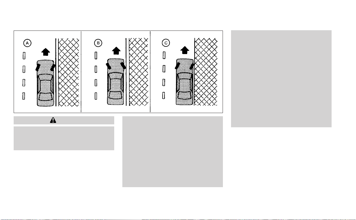
WARNING
• Do not stop or park the vehicle over
flammable materials such as dry
grass, waste paper or rags. They may
ignite and cause a fire.
• Safe parking procedures require that
both the parking brake be set and the
transmission placed into P (Park).
Failure to do so could cause the ve-
hicle to move unexpectedly or roll
away and result in an accident. Make
sure the shift lever has been pushed
as far forward as it can go and cannot
be moved without depressing the
foot brake pedal.
• Never leave the engine running while
the vehicle is unattended.
• Do not leave children unattended in-
side the vehicle. They could unknow-
ingly activate switches or controls or
make the vehicle move. Unattended
children could become involved in
serious accidents.
• To help avoid risk of injury or death
through unintended operation of the
vehicle and/or its systems, do not
leave children, people who require
the assistance of others or pets unat-
tended in your vehicle. Additionally,
the temperature inside a closed ve-
hicle on a warm day can quickly be-
come high enough to cause a signifi-
cant risk of injury or death to people
and pets.
1. Firmly apply the parking brake.
2. Move the shift lever to the P (Park)
position.
3. To help prevent the vehicle from rolling
into traffic when parked on an incline, it
is a good practice to turn the wheels as
illustrated.
• HEADED DOWNHILL WITH CURB
O
A
:
Turn the wheels into the curb and
WSD0050
PARKING/PARKING ON HILLS
5-146 Starting and driving

move the vehicle forward until the
curb side wheel gently touches the
curb.
• HEADED UPHILL WITH CURB
O
B
:
Turn the wheels away from the curb
and move the vehicle back until the
curb side wheel gently touches the
curb.
• HEADED UPHILL OR DOWNHILL, NO
CURB
O
C
:
Turn the wheels toward the side of the
road so the vehicle will move away
from the center of the road if it moves.
4. Place the ignition switch in the LOCK
position.
WARNING
• If the engine is not running or is
turned off while driving, the power
assist for the steering will not work.
Steering will be harder to operate.
• When the power steering warning
light illuminates with the engine run-
ning, there will be no power assist for
the steering. You will still have control
of the vehicle, but the steering will be
much harder to operate. Have the
power steering system checked. It is
recommended that you visit a
NISSAN dealer for this service.
The power steering system is designed to
provide power assistance while driving to
operate the steering wheel with light force.
When the steering wheel is operated re-
peatedly or continuously while parking or
driving at a very low speed, the power as-
sist for the steering wheel will be reduced.
This is to prevent overheating of the power
steering system and protect it from getting
damaged. While the power assist is re-
duced, steering wheel operation will be-
come heavy. If the steering wheel opera-
tion is still performed, the power steering
may stop and the power steering warning
light will illuminate. In a safe location, stop
the engine and place the ignition switch in
the OFF position. The temperature of the
power steering system will go down after a
period of time and the power assist level
will return to normal after starting the en-
gine. The power steering warning light will
go off. Avoid repeating such steering wheel
operations that could cause the power
steering system to overheat.
You may hear a noise from the front of the
vehicle when the steering wheel is oper-
ated. This is a normal operational noise
and is not a malfunction.
If the power steering warning light illumi-
nates while the engine is running, it may
indicate the power steering system is not
functioning properly and may need servic-
ing. Have the power steering system
checked. It is recommended that you visit a
NISSAN dealer for this service.
When the power steering warning light illu-
minates with the engine running, the
power assist for the steering will cease op-
eration but you will still have control of the
vehicle. At this time, greater steering efforts
are required to operate the steering wheel,
especially in sharp turns and at low speeds.
POWER STEERING
Starting and driving 5-147

The brake system has two separate hy-
draulic circuits. If one circuit malfunctions,
you will still have braking at two wheels.
BRAKE PRECAUTIONS
Vacuum assisted brakes
The brake booster aids braking by using
engine vacuum. If the engine stops, you
can stop the vehicle by depressing the
brake pedal. However, greater foot pres-
sure on the brake pedal will be required to
stop the vehicle and stopping distance will
be longer.
Using the brakes
Avoid resting your foot on the brake pedal
while driving. This will overheat the brakes,
wear out the brake pads faster, and reduce
gas mileage.
To help reduce brake wear and to prevent
the brakes from overheating, reduce speed
and downshift to a lower gear before going
down a slope or long grade. Overheated
brakes may reduce braking performance
and could result in loss of vehicle control.
WARNING
• While driving on a slippery surface,
be careful when braking, accelerat-
ing or downshifting. Abrupt braking
or accelerating could cause the
wheels to skid and result in an
accident.
• If the engine is not running or is
turned off while driving, the power
assist for the brakes will not work.
Braking will be harder.
Wet brakes
When the vehicle is washed or driven
through water, the brakes may get wet. As
a result, your braking distance will be lon-
ger and the vehicle may pull to one side
during braking.
To dry the brakes, drive the vehicle at a safe
speed while lightly pressing the brake
pedal to heat up the brakes. Do this until
the brakes return to normal. Avoid driving
the vehicle at high speeds until the brakes
function correctly.
Parking brake break-in
Break in the parking brake shoes whenever
the stopping effect of the parking brake is
weakened or whenever the parking brake
shoes and/or drums/rotors are replaced,
in order to assure the best braking
performance.
This procedure is described in the vehicle
service manual. It is recommended that
you visit a NISSAN dealer for this service.
ANTI-LOCK BRAKING SYSTEM (ABS)
WARNING
• The ABS is a sophisticated device, but
it cannot prevent accidents resulting
from careless or dangerous driving
techniques. It can help maintain ve-
hicle control during braking on slip-
pery surfaces. Remember that stop-
ping distances on slippery surfaces
will be longer than on normal sur-
faces even with ABS. Stopping dis-
tances may also be longer on rough,
gravel or snow covered roads, or if
you are using tire chains. Always
maintain a safe distance from the ve-
hicle in front of you. Ultimately, the
driver is responsible for safety.
BRAKE SYSTEM
5-148 Starting and driving

• Tire type and condition may also af-
fect braking effectiveness.
– When replacing tires, install the
specified size of tires on all four
wheels.
– When installing a spare tire, make
sure that it is the proper size and
type as specified on the Tire and
Loading Information label. For ad-
ditional information, see “Tire and
Loading Information label”
(P. 10-14).
– For additional information, see
“Wheels and tires” (P. 8-29).
The ABS controls the brakes so the wheels
do not lock during hard braking or when
braking on slippery surfaces. The system
detects the rotation speed at each wheel
and varies the brake fluid pressure to pre-
vent each wheel from locking and sliding.
By preventing each wheel from locking, the
system helps the driver maintain steering
control and helps to minimize swerving
and spinning on slipper y surfaces.
Using the system
Depress the brake pedal and hold it down.
Depress the brake pedal with firm steady
pressure, but do not pump the brakes. The
Anti-lock Braking System will operate to
prevent the wheels from locking up. Steer
the vehicle to avoid obstacles.
WARNING
Do not pump the brake pedal. Doing so
may result in increased stopping
distances.
Self-test feature
The Anti-lock Braking System (ABS) in-
cludes electronic sensors, electric pumps,
hydraulic solenoids and a computer. The
computer has a built-in diagnostic feature
that tests the system each time you start
the engine and move the vehicle at a low
speed in forward or reverse. When the self-
test occurs, you may hear a “clunk” noise
and/or feel a pulsation in the brake pedal.
This is normal and does not indicate a mal-
function. If the computer senses a mal-
function, it switches the ABS off and illumi-
nates the ABS warning light on the
instrument panel. The brake system then
operates normally but without anti-lock
assistance.
If the ABS warning light illuminates during
the self-test or while driving, have the ve-
hicle checked. It is recommended that you
visit a NISSAN dealer for this service.
Normal operation
The Anti-lock Braking System (ABS) oper-
ates at speeds above3-6mph(5-10
km/h). The speed varies according to road
conditions.
When the ABS senses that one or more
wheels are close to locking up, the actuator
rapidly applies and releases hydraulic pres-
sure. This action is similar to pumping the
brakes very quickly. You may feel a pulsa-
tion in the brake pedal and hear a noise
from under the hood or feel a vibration
from the actuator when it is operating. This
is normal and indicates that the ABS is op-
erating properly. However, the pulsation
may indicate that road conditions are haz-
ardous and extra care is required while
driving.
Starting and driving 5-149

BRAKE ASSIST
When the force applied to the brake pedal
exceeds a certain level, the Brake Assist is
activated generating greater braking force
than a conventional brake booster even
with light pedal force.
WARNING
The Brake Assist is only an aid to assist
braking operation and is not a collision
warning or avoidance device. It is the
driver’s responsibility to stay alert,
drive safely and be in control of the ve-
hicle at all times.
The VDC system uses various sensors to
monitor driver inputs and vehicle motion.
Under certain driving conditions, the VDC
system helps to perform the following
functions:
• Controls brake pressure to reduce wheel
slip on one slipping drive wheel so power
is transferred to a non-slipping drive
wheel on the same axle.
• Controls brake pressure and engine out-
put to reduce drive wheel slip based on
vehicle speed (traction control function).
• Controls brake pressure at individual
wheels and engine output to help the
driver maintain control of the vehicle in
the following conditions:
– Understeer (vehicle tends to not follow
the steered path despite increased
steering input)
– Oversteer (vehicle tends to spin due to
certain road or driving conditions)
The VDC system can help the driver to
maintain control of the vehicle, but it can-
not prevent loss of vehicle control in all driv-
ing situations.
When the VDC system operates, the
indicator light in the instrument panel
flashes to note the following:
• The road may be slippery or the system
may determine some action is required
to help keep the vehicle on the steered
path.
• You may feel a pulsation in the brake
pedal and hear a noise or vibration from
under the hood. This is normal and indi-
cates that the VDC system is working
properly.
• Adjust your speed and driving to the road
conditions.
For additional information, see “Slip indica-
tor light” (P. 2-17) and “Vehicle Dynamic Con-
trol (VDC) OFF indicator light” (P. 2-17).
If a malfunction occurs in the system, the
indicator light comes on in the instru-
ment panel. The VDC system automatically
turns off when the indicator light is on.
VEHICLE DYNAMIC CONTROL (VDC)
SYSTEM
5-150 Starting and driving
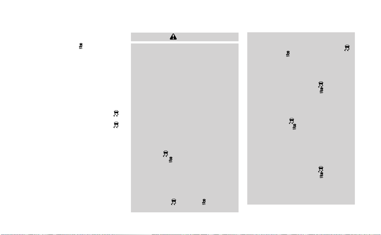
The vehicle information display is used to
turn off the VDC system. When the VDC
system is turned off, the
indicator light
and if so equipped, the RAB system warn-
ing light, AEB system warning light and AEB
with Pedestrian Detection system warning
light illuminate to indicate the VDC, AEB,
AEB with Pedestrian Detection, and RAB
systems are off.
When the VDC system is turned off in the
vehicle information display, the VDC sys-
tem still operates to prevent one drive
wheel from slipping by transferring power
to a non-slipping drive wheel. The
indicator light flashes if this occurs. All
other VDC functions are off and the
indicator light will not flash.
The VDC system is automatically reset to
ON when the ignition switch is placed in the
OFF position then back to the ON position.
The computer has a built-in diagnostic fea-
ture that tests the system each time you
start the engine and move the vehicle for-
ward or in reverse at a slow speed. When
the self-test occurs, you may hear a clunk
noise and/or feel a pulsation in the brake
pedal. This is normal and is not an indica-
tion of a malfunction.
WARNING
• The VDC system is designed to help
the driver maintain stability but does
not prevent accidents due to abrupt
steering operation at high speeds or
by careless or dangerous driving
techniques. Reduce vehicle speed
and be especially careful when driv-
ing and cornering on slippery sur-
faces and always drive carefully.
• Do not modify the vehicle's suspen-
sion. If suspension parts such as
shock absorbers, struts, springs, sta-
bilizer bars, bushings and wheels are
not NISSAN recommended for your
vehicle or are extremely deterio-
rated, the VDC system may not oper-
ate properly. This could adversely af-
fect vehicle handling performance,
and the
indicator light may flash
or the
indicator light may
illuminate.
• If brake related parts such as brake
pads, rotors and calipers are not
NISSAN recommended or are ex-
tremely deteriorated, the VDC sys-
tem may not operate properly and
both the
and indicator
lights may illuminate.
• If engine control related parts are not
NISSAN recommended or are ex-
tremely deteriorated, both the
and the indicator lights may
illuminate.
• When driving on extremely inclined
sur faces such as higher banked cor-
ners, the VDC system may not oper-
ate properly and the
indicator
light may flash or the
indicator
light may illuminate. Do not drive on
these types of roads.
• When driving on an unstable surface
such as a turntable, ferry, elevator or
ramp, the
indicator light may
flash or the
indicator light may
illuminate. This is not a malfunction.
Restart the engine after driving onto
a stable surface.
• If wheels or tires other than the
NISSAN recommended ones are
used, the VDC system may not oper-
ate properly and the
indicator
light may flash or the
indicator
light may illuminate.
• The VDC system is not a substitute
for winter tires or tire chains on a
snow covered road.
Starting and driving 5-151

BRAKE FORCE DISTRIBUTION
During braking while driving through turns,
the system optimizes the distribution of
force to each of the front and rear wheels
depending on the radius of the turn.
WARNING
• The VDC system is designed to help
the driver maintain stability but does
not prevent accidents due to abrupt
steering operation at high speeds or
by careless or dangerous driving
techniques. Reduce vehicle speed
and be especially careful when driv-
ing and cornering on slippery sur-
faces and always drive carefully.
• Do not modify the vehicle's suspen-
sion. If suspension parts such as
shock absorbers, struts, springs, sta-
bilizer bars, bushings and wheels are
not NISSAN recommended for your
vehicle or are extremely deterio-
rated, the VDC system may not oper-
ate properly. This could adversely af-
fect vehicle handling performance,
and the
indicator light may flash
or the
indicator light may
illuminate.
• If brake related parts such as brake
pads, rotors and calipers are not
NISSAN recommended or are ex-
tremely deteriorated, the VDC sys-
tem may not operate properly and
both the
and indicator light
may illuminate.
• If engine control related parts are not
NISSAN recommended or are ex-
tremely deteriorated, both the
and the
indicator light may
illuminate.
• When driving on extremely inclined
sur faces such as higher banked cor-
ners, the VDC system may not oper-
ate properly and the
indicator
light may flash or the
indicator
light may illuminate. Do not drive on
these types of roads.
• When driving on an unstable surface
such as a turntable, ferry, elevator or
ramp, the
indicator light may
flash or the
indicator light may
illuminate. This is not a malfunction.
Restart the engine after driving onto
a stable surface.
• If wheels or tires other than the
NISSAN recommended ones are
used, the VDC system may not oper-
ate properly and the
indicator
light may flash or the
indicator
light may illuminate.
• The VDC system is not a substitute
for winter tires or tire chains on a
snow covered road.
5-152 Starting and driving

The chassis control is an electric control
module that includes the following
functions:
• Intelligent Trace Control
• Active Ride Control
INTELLIGENT TRACE CONTROL
(I-TC)
This system senses driving based on the
driver’s steering and acceleration/braking
patterns, and controls brake pressure at
individual wheels to aid tracing at corners
and help smooth vehicle response.
The I-TC can be set to on (enabled) or off
(disabled) through the vehicle information
display “Settings” page. For additional infor-
mation, see “Vehicle information display —
5 inch (13 cm) Type A (if so equipped)”
(P. 2-18) or “Vehicle information display — 7
inch (18 cm) Type B (if so equipped)” (P. 2-33).
When the VDC system is turned off, the I-TC
is also turned off.
WARNING
The I-TC may not be effective depend-
ing on the driving condition. Always
drive carefully and attentively.
When the I-TC is operating, you may feel a
pulsation in the brake pedal and hear a
noise. This is normal and indicates that the
I-TC is operating properly.
Even if the I-TC is turned off, some functions
will remain on to assist the driver (for ex-
ample, avoidance scenes).
ACTIVE RIDE CONTROL (ARC)
This system senses upper body motion
(based on wheel speed information) and
controls engine torque and four wheel
brake pressure. This will enhance ride com-
fort in effort to restrain uncomfortable up-
per body movement when passing over
undulated road surfaces. This system
comes into effect above 25 mph (40 km/h).
When the VDC system is turned off, the ARC
is also turned off.
When the ARC is operating, you may hear
noise and sense slight deceleration. This is
normal and indicates that the ARC is oper-
ating properly.
WARNING
• Never rely solely on the hill start as-
sist system to prevent the vehicle
from moving backward on a hill. Al-
ways drive carefully and attentively.
Depress the brake pedal when the
vehicle is stopped on a steep hill. Be
especially careful when stopped on a
hill on frozen or muddy roads. Failure
to prevent the vehicle from rolling
backwards may result in a loss of
control of the vehicle and possible
serious injury or death.
• The hill start assist system is not de-
signed to hold the vehicle at a stand-
still on a hill. Depress the brake pedal
when the vehicle is stopped on a
steep hill. Failure to do so may cause
the vehicle to roll backwards and
may result in a collision or serious
personal injury.
• The hill start assist system may not
prevent the vehicle from rolling
backwards on a hill under all load or
road conditions. Always be prepared
to depress the brake pedal to prevent
the vehicle from rolling backwards.
Failure to do so may result in a colli-
sion or serious personal injury.
CHASSIS CONTROL (if so equipped) HILL START ASSIST SYSTEM
Starting and driving 5-153

When the vehicle is stopped on a hill, the hill
start assist system automatically keeps
the brakes applied to help prevent the ve-
hicle from rolling backward in the time it
takes the driver to release the brake pedal
and apply the accelerator.
The hill start assist system will operate au-
tomatically under the following conditions:
• The transmission is shifted to a forward
or reverse gear.
• The vehicle is stopped completely on a
hill by applying the brake. The maximum
holding time is 2 seconds. After 2 sec-
onds the vehicle will begin to roll back and
the hill start assist system will stop oper-
ating completely.
The hill start assist system will not operate
when the shift lever is placed in the N (Neu-
tral) or P (Park) position or on a flat and level
road.
The RSS sounds a tone to inform the driver
of obstacles near the bumper.
When the “DISPLAY” key is on, the sonar
view will automatically appear in the
touch-screen display. An additional view of
the sonar status will appear in the vehicle
information display for reference.
WARNING
• The RSS is a convenience but it is not
a substitute for proper parking.
• The driver is always responsible for
safety during parking and other ma-
neuvers. Always look around and
check that it is safe to do so before
parking.
• Read and understand the limitations
of the RSS as contained in this sec-
tion. The colors of the corner sonar
indicator and the distance guide
lines in the rear view indicate differ-
ent distances to the object.
• Inclement weather or ultrasonic
sources such as an automatic car
wash, a truck's compressed-air
brakes or a pneumatic drill may af-
fect the function of the system; this
may include reduced performance or
a false activation.
• This function is designed as an aid to
the driver in detecting large station-
ary objects to help avoid damaging
the vehicle.
LSD3247
REAR SONAR SYSTEM (RSS) (if so
equipped)
5-154 Starting and driving
• The system is not designed to pre-
vent contact with small or moving
objects. Always move slowly. The
system will not detect small objects
below the bumper, and may not de-
tect objects close to the bumper or
on the ground.
• The system may not detect the fol-
lowing objects: fluffy objects such as
snow, cloth, cotton, glass, wool, etc.;
thin objects such as rope, wire and
chain, etc.; or wedge-shaped objects.
• The rear sonar sensors may detect a
sound wave reflected from the sur-
face of an obstacle when a horn, etc.
sounds or there is an ultrasonic
source (such as parking sensors of
other vehicles) around the vehicle
because the rear sonar sensors de-
tect the distance between the vehicle
and the obstacle by detecting the
sound wave reflected from the sur-
face of an obstacle.
If your vehicle sustains damage to the
bumper fascia, leaving it misaligned or
bent, the sensing zone may be altered
causing inaccurate measurement of ob-
stacles or false alarms.
CAUTION
• Excessive noise (such as audio sys-
tem volume or an open vehicle win-
dow) will interfere with the tone and
it may not be heard.
• Keep the sonar sensors (located on
the bumper fascia) free from snow,
ice and large accumulations of dirt.
Do not clean the sensors with sharp
objects. If the sensors are covered,
the accuracy of the sonar function
will be diminished.
SYSTEM OPERATION
The system informs with a visual and au-
dible alert of rear obstacles when the shift
lever is in the R (Reverse) position.
Sonar Operation Table
RR Sensor
Range Sound Display
Roo
o – Display/Beep when detect
† – Display on camera view
x – No Display and Beep
The system is deactivated at speeds above
6 mph (10 km/h). It is reactivated at lower
speeds.
The intermittent tone will stop after 3 sec-
onds when an obstacle is detected by only
the corner sensor and the distance does
not change. The tone will stop when the
obstacle gets away from the vehicle.
When the object is detected, the indicator
(green) appears and blinks and the tone
sounds intermittently. When the vehicle
moves closer to the object, the color of the
indicator turns yellow and the rate of the
blinking increases. When the vehicle is very
close to the object, the indicator stops
blinking and turns red, and the tone
sounds continuously.
Starting and driving 5-155

When the corner of the vehicle moves
closer to an object, the corner sonar indi-
cator
O
A
appears. When the center of the
vehicle moves close to an object, the cen-
ter sonar indicator
O
B
appears.
The system indicators
O
A
will appear when
the vehicle moves closer to an object.
LSD3246 LSD2137
5-156 Starting and driving

HOW TO ENABLE/DISABLE THE
SONAR SYSTEM
The system is automatically activated
when the ignition is in the ON position and
the shift lever is in the R (Reverse) position.
Perform the following steps to enable or
disable the sonar system:
For vehicles with 7 inch (18 cm) display.
1. Press the
button until “Settings” dis-
plays in the vehicle information display.
Use the
button to select “Driver As-
sistance.” Then press the OK button.
2. Select “Parking Aids” and press the OK
button.
3. Select “Rear” and press the OK button to
turn the system on or off.
– Select “Auto Show Sonar” to display the
parking sensor in the vehicle information
display when the sonar system
activates.
– Select “Distance” to change the sonar
system distance to “Long,” “Medium” or
“Short.”
LSD3240
For vehicles with the 7 inch (18 cm) display
Starting and driving 5-157

For vehicles with 5 inch (13 cm) display.
1. Press the
button until “Settings” dis-
plays in the vehicle information display.
Use the
button to select “Driver As-
sistance.” Then press the OK button.
2. Select “Parking Aids” and press the OK
button.
3. Select “Rear Sensor” and press the OK
button to turn the system on or off.
– Select “Display” to display the parking
sensor in the vehicle information display
when the sonar system activates.
– Select “Range” to change the sonar sys-
tem distance to “Far,” “Mid.” or “Near.”
LSD3931
For vehicles with the 5 inch (13 cm) display
5-158 Starting and driving

SONAR LIMITATIONS
WARNING
Listed below are the system limitations
for the sonar system. Failure to operate
the vehicle in accordance with these
system limitations could result in seri-
ous injury or death.
• The system is deactivated at speeds
above 6 mph (10 km/h). It is reacti-
vated at lower speeds.
• Inclement weather or ultrasonic
sources such as an automatic car
wash, a truck’s compressed-air
brakes or a pneumatic drill may af-
fect the function of the system; this
may include reduced performance or
a false activation.
• The system is not designed to pre-
vent contact with small or moving
objects. Always move slowly. The
system will not detect small objects
below the bumper or on the ground.
• The system may not detect the fol-
lowing objects: fluffy objects such as
snow, cloth, cotton, glass-wool, etc.;
thin objects such as rope, wire and
chain, etc.; or wedge-shaped objects.
• The system may not detect objects
at speeds above 3 mph (5 km/h) and
may not detect certain angular or
moving objects.
SYSTEM TEMPORARILY
UNAVAILABLE
When sonar blockage is detected, the sys-
tem will be deactivated automatically.
The system is not available until the condi-
tions no longer exist.
The sonar sensors may be blocked by tem-
porary ambient conditions such as splash-
ing water, mist or fog. The blocked condi-
tion may also be caused by objects such as
ice, frost or dirt obstructing the sonar
sensors.
Action to take:
When the above conditions no longer exist,
the system will resume automatically.
SYSTEM MAINTENANCE
The sonar sensors
O
1
are located on the
rear bumper. Always keep the area near
the sonar sensors clean.
The sonar sensors may be blocked by tem-
porary ambient conditions such as splash-
ing water, mist or fog.
The blocked condition may also be caused
by objects such as ice, frost or dirt ob-
structing the sonar sensors.
Check for and remove objects obstructing
the area around the sonar sensors.
LSD3241
Starting and driving 5-159

Do not attach stickers (including transpar-
ent material), install accessories or apply
additional paint near the sonar sensors.
Do not strike or damage the area around
the sonar sensors. It is recommended that
you visit a NISSAN dealer if the area around
the sonar sensors is damaged due to a
collision.
FREEING A FROZEN DOOR LOCK
To prevent a door lock from freezing, apply
de-icer through the key hole. If the lock
becomes frozen, heat the key before in-
serting it into the key hole or use the re-
mote keyless entry function on the Intelli-
gent Key.
ANTIFREEZE
In the winter when it is anticipated that the
temperature will drop below 32°F (0°C),
check the antifreeze to assure proper win-
ter protection. For additional information,
see “Engine cooling system” (P. 8-5).
BATTERY
If the battery is not fully charged during
extremely cold weather conditions, the
battery fluid may freeze and damage the
battery. To maintain maximum efficiency,
the battery should be checked regularly.
For additional information, see “Battery”
(P. 8-14).
DRAINING OF COOLANT WATER
If the vehicle is to be left outside without
antifreeze,drain the cooling system, includ-
ing the engine block. Refill before operating
the vehicle. For additional information, see
“Changing engine coolant” (P. 8-6).
TIRE EQUIPMENT
1. SUMMER tires have a tread designed to
provide superior per formance on dry
pavement. However, the performance of
these tires will be substantially reduced
in snowy and icy conditions. If you oper-
ate your vehicle on snowy or icy roads,
NISSAN recommends the use of MUD &
SNOW or ALL SEASON TIRES on all four
wheels. It is recommended that you visit
a NISSAN dealer for the tire type, size,
speed rating and availability information.
2. For additional traction on icy roads,
studded tires may be used. However,
some U.S. states and Canadian prov-
inces prohibit their use. Check local,
state and provincial laws before install-
ing studded tires.
Skid and traction capabilities of studded
snow tires on wet or dry surfaces may be
poorer than that of non-studded snow
tires.
3. Tire chains may be used. For additional
information, see “Tire chains” (P. 8-37).
COLD WEATHER DRIVING
5-160 Starting and driving

SPECIAL WINTER EQUIPMENT
It is recommended that the following items
be carried in the vehicle during winter:
• A scraper and stiff-bristled brush to re-
move ice and snow from the windows
and wiper blades.
• A sturdy, flat board to be placed under the
jack to give it firm support.
• A shovel to dig the vehicle out of
snowdrifts.
• Extra washer fluid to refill the windshield-
washer fluid reservoir.
DRIVING ON SNOW OR ICE
WARNING
• Wet ice (32°F, 0°C and freezing rain),
very cold snow or ice can be slick and
very hard to drive on. The vehicle will
have much less traction or “grip” un-
der these conditions. Try to avoid
driving on wet ice until the road is
salted or sanded.
• Whatever the condition, drive with
caution. Accelerate and slow down
with care. If accelerating or down-
shifting too fast, the drive wheels will
lose even more traction.
• Allow more stopping distance under
these conditions. Braking should be
started sooner than on dry
pavement.
• Allow greater following distances on
slippery roads.
• Watch for slippery spots (glare ice).
These may appear on an otherwise
clear road in shaded areas. If a patch
of ice is seen ahead, brake before
reaching it. Try not to brake while on
the ice, and avoid any sudden steer-
ing maneuvers.
• Do not use the cruise control on slip-
pery roads.
• Snow can trap dangerous exhaust
gases under your vehicle. Keep snow
clear of the exhaust pipe and from
around your vehicle.
ENGINE BLOCK HEATER (if so
equipped)
Engine block heaters are used to assist
with cold temperature starting.
The engine block heater should be used
when the outside temperature is 20°F (-7°C)
or lower.
WARNING
• Do not use your engine block heater
with an ungrounded electrical sys-
tem or a 2-pronged adapter. You can
be seriously injured by an electrical
shock if you use an ungrounded
connection.
• Disconnect and properly store the
engine block heater cord before
starting the engine. Damage to the
cord could result in an electrical
shock and can cause serious injury.
• Use a heavy-duty 3-wire, 3-pronged
extension cord rated for at least 10 A.
Plug the extension cord into a
Ground Fault Interrupt (GFI) pro-
tected, grounded 110-VAC outlet.
Failure to use the proper extension
cord or a grounded outlet can result
in a fire or electrical shock and cause
serious personal injury.
Starting and driving 5-161

To use the engine block heater:
1. Turn the engine off.
2. Open the hood and unwrap the engine
block heater cord.
3. Plug the engine block heater cord into a
grounded 3-wire, 3-pronged extension
cord.
4. Plug the extension cord into a Ground
Fault Interrupt (GFI) protected, grounded
110-volt AC (VAC) outlet.
5. The engine block heater must be
plugged in for at least 2–4 hours, de-
pending on outside temperatures, to
properly warm the engine coolant. Use
an appropriate timer to turn the engine
block heater on.
6. Before starting the engine, unplug and
properly store the cord to keep it away
from moving parts.
ACTIVE NOISE CANCELLATION
This system uses microphones
O
1
located
inside the vehicle to detect engine boom-
ing noise. The system then automatically
generates a noise canceling sound
through the speakers and woofer (if so
equipped) to reduce engine booming
noise.
NOTE:
To operate the active noise cancella-
tion system properly:
• Do not cover the speakers or woofer (if
so equipped).
• Do not cover the microphones.
• Do not change or modify speakers in-
cluding the woofer (if so equipped) and
any audio related components such as
the amplifier.
• Do not make any modification includ-
ing sound deadening or modifications
around the microphones or speakers.
ACTIVE SOUND ENHANCEMENT
Active sound enhancement enhances ex-
isting engine sounds according to the en-
gine speed and driving modes through the
speakers and woofer (if so equipped).
LSD3483
Front Microphone
LSD3261
Rear Microphones
ACTIVE NOISE CANCELLATION/
ACTIVE SOUND ENHANCEMENT (if so
equipped)
5-162 Starting and driving

6 In case of emergency
Hazard warning flasher switch ..................6-2
Emergency engine shut off ......................6-2
Flat tire ..........................................6-3
Tire Pressure Monitoring System
(TPMS) .......................................6-3
Changing a flat tire ...........................6-4
Jump starting ...................................6-11
Push starting ...................................6-13
If your vehicle overheats........................6-13
Towing your vehicle ............................6-14
Towing recommended by NISSAN ...........6-14
Vehicle recovery
(freeing a stuck vehicle) .....................6-16

Push the switch on to warn other drivers
when you must stop or park under emer-
gency conditions. All turn signal lights flash.
WARNING
• If stopping for an emergency, be sure
to move the vehicle well off the road.
• Do not use the hazard warning flash-
ers while moving on the highway un-
less unusual circumstances force
you to drive so slowly that your ve-
hicle might become a hazard to other
traffic.
• Turn signals do not work when the
hazard warning flasher lights are on.
The flashers will operate with the ignition
switch placed in any position.
Some jurisdictions may prohibit the use
of the hazard warning flasher switch
while driving.
To shut off the engine in an emergency
situation while driving, perform the follow-
ing procedure:
– Rapidly push the push-button ignition
switch three consecutive times in less
than 1.5 seconds, or
– Push and hold the push-button ignition
switch for more than 2 seconds.
LIC0394
HAZARD WARNING FLASHER SWITCH EMERGENCY ENGINE SHUT OFF
6-2 In case of emergency

TIRE PRESSURE MONITORING
SYSTEM (TPMS)
This vehicle is equipped with the Tire Pres-
sure Monitoring system (TPMS). It monitors
tire pressure of all tires except the spare.
When the low tire pressure warning light is
lit, and the “Tire Pressure Low - Add Air”
warning appears in the vehicle information
display, one or more of your tires is signifi-
cantly under-inflated. If equipped, the sys-
tem also displays pressure of all tires (ex-
cept the spare tire) on the display screen by
sending a signal from a sensor that is in-
stalled in each wheel. If the vehicle is being
driven with low tire pressure, the TPMS will
activate and warn you of it by the low tire
pressure warning light. This system will ac-
tivate only when the vehicle is driven at
speeds above 16 mph (25 km/h). For addi-
tional information, see “Warning lights, indi-
cator lights and audible reminders” (P. 2-9)
and “Tire Pressure Monitoring System
(TPMS)” (P. 5-5).
WARNING
• Radio waves could adversely affect
electric medical equipment. Those
who use a pacemaker should contact
the electric medical equipment
manufacturer for the possible influ-
ences before use.
• If the low tire pressure warning light
illuminates while driving, avoid sud-
den steering maneuvers or abrupt
braking, reduce vehicle speed, pull
off the road to a safe location and
stop the vehicle as soon as possible.
Driving with under-inflated tires may
permanently damage the tires and
increase the likelihood of tire failure.
Serious vehicle damage could occur
and may lead to an accident and
could result in serious personal in-
jury. Check the tire pressure for all
four tires. Adjust the tire pressure to
the recommended COLD tire pres-
sure shown on the Tire and Loading
Information label to turn the low tire
pressure warning light OFF. If the
light still illuminates while driving af-
ter adjusting the tire pressure, a tire
may be flat or the TPMS may be mal-
functioning. If you have a flat tire, re-
place it with a spare tire as soon as
possible. If no tire is flat and all tires
are properly inflated, have the ve-
hicle checked. It is recommended
that you visit a NISSAN dealer for this
service.
• When using a wheel without the
TPMS such as the spare tire, the TPMS
will not function and the low tire
pressure warning light will flash for
approximately one minute. Have
your tires replaced and/or TPMS sys-
tem reset as soon as possible. It is
recommended that you visit a
NISSAN dealer for these services.
• Replacing tires with those not origi-
nally specified by NISSAN could af-
fect the proper operation of the
TPMS.
• Do not inject any tire liquid or aerosol
tire sealant into the tires, as this may
cause a malfunction of the tire pres-
sure sensors.
FLAT TIRE
In case of emergency 6-3

CHANGING A FLAT TIRE
If you have a flat tire, follow the instructions
below:
Stopping the vehicle
1. Safely move the vehicle off the road and
away from traffic.
2. Turn on the hazard warning flashers.
3. Park on a level surface and apply the
parking brake. Move the shift lever to P
(Park).
4. Turn off the engine.
5. Raise the hood to warn other traffic and
to signal professional road assistance
personnel that you need assistance.
6. Have all passengers get out of the ve-
hicle and stand in a safe place, away
from traffic and clear of the vehicle.
WARNING
• Make sure the parking brake is se-
curely applied and the Continuously
Variable Transmission (CVT) is
shifted into P (Park).
• Never change tires when the vehicle
is on a slope, ice or slippery areas.
This is hazardous.
• Never change tires if oncoming traf-
fic is close to your vehicle. Wait for
professional road assistance.
Blocking wheels
Place suitable blocks at both the front and
back of the wheel diagonally opposite the
flat tire to prevent the vehicle from moving
when it is jacked up.
WARNING
Be sure to block the wheel as the ve-
hicle may move and result in personal
injury.
LCE2142
A. Blocks
B. Flat tire
6-4 In case of emergency
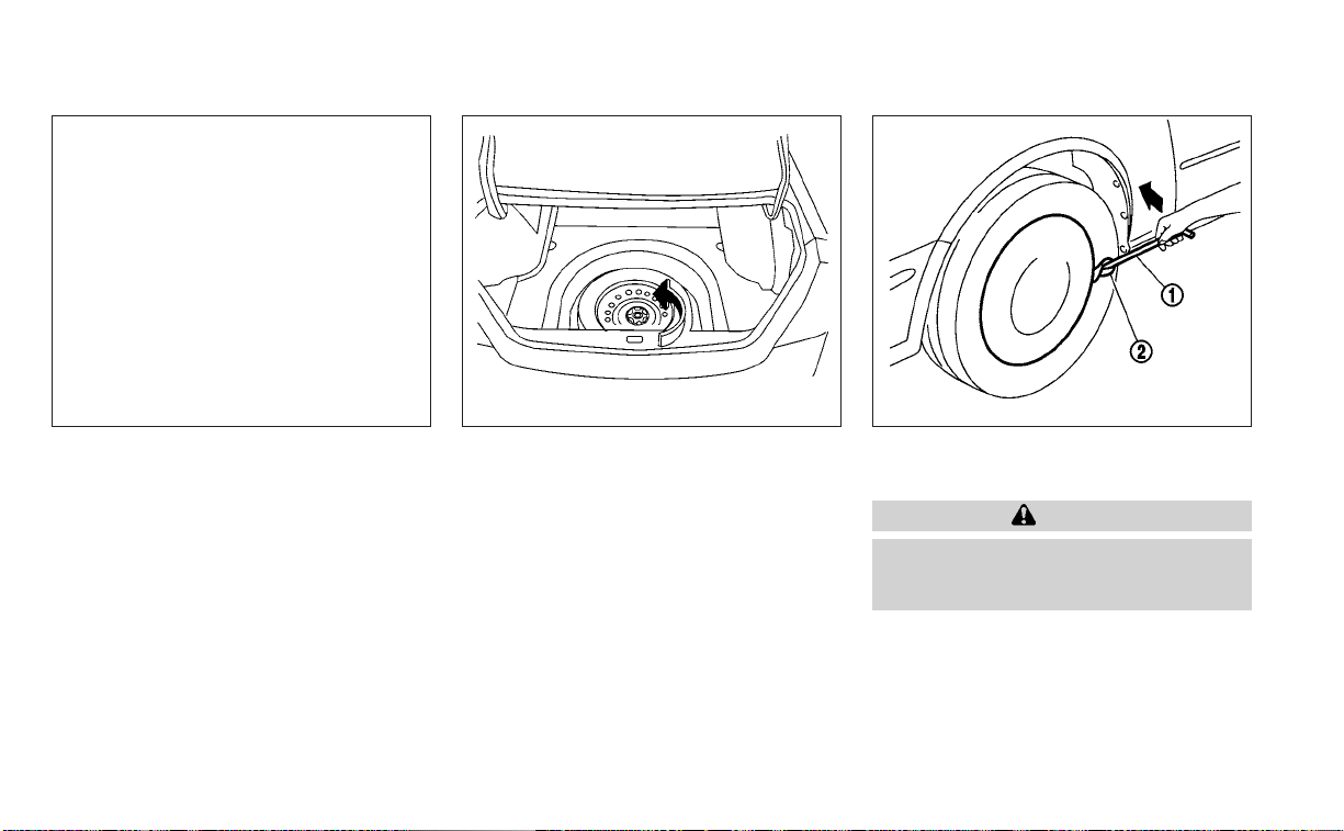
Getting the spare tire and tools
Open the trunk. Lift the luggage floor. Re-
move the wheel nut wrench
O
1
and the
jack
O
2
from the storage cover
O
3
. Then
remove the tool storage cover
O
3
to ac-
cess the spare tire.
Turn the clamp to remove the spare tire.
Remove the spare tire.
For AWD vehicles - the TEMPORARY USE
ONLY spare tire must be installed to the
rear wheels only. If a front tire is punctured,
install the original rear tire onto the front
wheel, then install the TEMPORARY USE
ONLY spare tire on the rear.
Removing wheel cover (if so
equipped)
CAUTION
Do not use your hands to pry off wheel
caps or wheel covers. Doing so could
result in personal injury.
To remove the wheel cover, use the jack rod
O
1
as illustrated.
Apply cloth
O
2
between the wheel and jack
rod to prevent damaging the wheel and
wheel cover.
Use caution not to scratch the wheel cover
or wheel surface.
LCE2434 WCE0067 SCE0630
In case of emergency 6-5

Jacking up vehicle and removing
the damaged tire (2WD models)
WARNING
• Never get under the vehicle while it is
supported only by the jack. If it is nec-
essary to work under the vehicle,
support it with safety stands.
• Use only the jack provided with your
vehicle to lift the vehicle. Do not use
the jack provided with your vehicle
on other vehicles. The jack is de-
signed for lifting only your vehicle
during a tire change.
• Use the correct jack-up points. Never
use any other part of the vehicle for
jack support.
• Never jack up the vehicle more than
necessary.
• Never use blocks on or under the
jack.
• Do not start or run the engine while
vehicle is on the jack. It may cause
the vehicle to move. This is especially
true for vehicles with limited slip
differentials.
• Do not allow passengers to stay in
the vehicle while it is on the jack.
• Never run the engine with a wheel(s)
off the ground. It may cause the ve-
hicle to move.
LCE2435
Jack-up point
6-6 In case of emergency
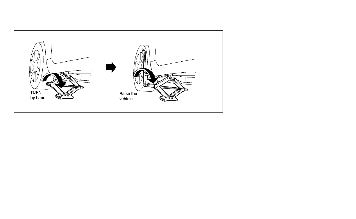
Always refer to the illustration for the cor-
rect placement and jack-up points for your
specific vehicle model and jack type.
Carefully read the caution label attached
to the jack body and the following in-
structions.
1. Loosen each wheel nut one or two turns
by turning counterclockwise with the
wheel nut wrench. Do not remove the
wheel nuts until the tire is off the
ground.
2. Place the jack directly under the jack-up
point as illustrated so the top of the jack
contacts the vehicle at the jack-up point.
Align the jack head between the two
notches in the front or the rear as
shown. Also fit the groove of the jack
head between the notches as shown.
NOTE:
Do not place jack on the notches be-
tween the front most and rear most
jacking points.
The jack should be used on firm and
level ground.
3. To lift the vehicle, securely hold the jack
lever and rod with both hands. Carefully
raise the vehicle until the tire clears the
ground. Remove the wheel nuts, and
then remove the tire.
LCE0020
In case of emergency 6-7

Jacking up vehicle and replacing
the damaged tire (AWD models)
WARNING
For AWD vehicles - the TEMPORARY USE
ONLY spare tire must be installed to the
rear wheels only. If a front tire is punc-
tured, install the original rear tire onto
the front wheel, then install the TEMPO-
RARY USE ONLY spare tire on the rear.
Failure to do so could cause overheat-
ing to the AWD system
WARNING
• Never get under the vehicle while it is
supported only by the jack. If it is nec-
essary to work under the vehicle,
support it with safety stands.
• Use only the jack provided with your
vehicle to lift the vehicle. Do not use
the jack provided with your vehicle
on other vehicles. The jack is de-
signed for lifting only your vehicle
during a tire change.
• Use the correct jack-up points. Never
use any other part of the vehicle for
jack support.
• Never jack up the vehicle more than
necessary.
• Never use blocks on or under the
jack.
• Do not start or run the engine while
vehicle is on the jack. It may cause
the vehicle to move. This is especially
true for vehicles with limited slip
differentials.
• Do not allow passengers to stay in
the vehicle while it is on the jack.
• Never run the engine with a wheel(s)
off the ground. It may cause the ve-
hicle to move.
LCE2435
Jack-up point
6-8 In case of emergency

Always refer to the illustration for the cor-
rect placement and jack-up points for your
specific vehicle model and jack type.
Carefully read the caution label attached
to the jack body and the following
instructions.
If a flat tire occurs on the front axle of AWD
vehicle, the spare tire must be applied to
the rear axle of the vehicle.
1. Loosen each wheel nut one or two turns
by turning counterclockwise with the
wheel nut wrench. Do not remove the
wheel nuts until the tire is off the
ground.
2. Place the jack directly under the jack-up
point as illustrated so the top of the jack
contacts the vehicle at the jack-up point.
Align the jack head between the two
notches in the front or the rear as
shown. Also fit the groove of the jack
head between the notches as shown.
NOTE:
Do not place jack on the notches be-
tween the front most and rear most
jacking points.
The jack should be used on firm and
level ground.
3. Jack up the rear axle of the vehicle. To lift
the vehicle, securely hold the jack lever
and rod with both hands. Carefully raise
the vehicle until the tire clears the
ground. Remove the wheel nuts, and
then remove the tire and set aside.
4. Apply the spare tire to the rear axle of the
vehicle, replace the wheel nuts and
tighten.
5. Lower the jack and further tighten the
wheel nuts to the recommended
torque, see “Installing the spare tire”
(P. 6-10).
6. Jack up the front axle of the vehicle and
remove the damaged wheel.
7. Apply the wheel that was removed from
the rear axle to the front axle of the ve-
hicle, replace the wheel nuts and tighten.
8. Lower the jack and further tighten the
wheel nuts to the recommended
torque, see “Installing the spare tire”
(P. 6-10).
LCE0020
In case of emergency 6-9
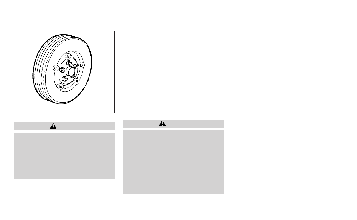
Installing the spare tire
WARNING
For AWD vehicles - the TEMPORARY USE
ONLY spare tire must be installed to the
rear wheels only. If a front tire is punc-
tured, install the original rear tire onto
the front wheel, then install the TEMPO-
RARY USE ONLY spare tire on the rear.
Failure to do so could cause overheat-
ing to the AWD system
The spare tire is designed for emergency
use. For additional information, see
“Wheels and tires” (P. 8-29).
1. Clean any mud or dirt from the surface
between the wheel and hub.
2. Carefully put the spare tire on and
tighten the wheel nuts finger tight.
3. With the wheel nut wrench, tighten
wheel nuts alternately and evenly in the
sequence illustrated (
O
A
,
O
B
,
O
C
,
O
D
,
O
E
)
until they are tight.
4. Lower the vehicle slowly until the tire
touches the ground. Then, with the
wheel nut wrench, tighten the wheel
nuts securely in the sequence illustrated
(
O
A
,
O
B
,
O
C
,
O
D
,
O
E
). Lower the vehicle
completely.
WARNING
• Incorrect wheel nuts or improperly
tightened wheel nuts can cause the
wheel to become loose or come off.
This could cause an accident.
• Do not use oil or grease on the wheel
studs or nuts. This could cause the
nuts to become loose.
• Retighten the wheel nuts when the
vehicle has been driven for 600 miles
(1,000 km) (also in cases of a flat tire,
etc.).
As soon as possible, tighten the wheel
nuts to the specified torque with a
torque wrench.
Wheel nut tightening torque:
83 ft-lb (113 N·m)
The wheel nuts must be kept tightened
to specification at all times. It is recom-
mended that wheel nuts be tightened to
specifications at each lubrication
interval.
Adjust tire pressure to the COLD
pressure.
COLD pressure: After vehicle has been
parked for 3 hours or more or driven less
than 1 mile (1.6 km).
COLD tire pressures are shown on the
Tire Load and Information label affixed
to the driver side center pillar.
After adjusting tire pressure to the COLD
tire pressure, the display (if so equipped)
of the tire pressure information may
show higher pressure than the COLD tire
pressure after the vehicle has been
driven more than 1 mile (1.6 km). This is
because the tire pressure increases as
the tire temperature rises. This does not
indicate a system malfunction.
WCE0056
6-10 In case of emergency

5. Securely store the flat tire in the tire well
and jacking equipment in the vehicle.
NOTE:
Remove the center wheel cap before
storing the flat tire.
6. Place the spare tire cover and the trunk
floor carpeting over the damaged tire.
7. Close the trunk.
WARNING
• Always make sure that the spare tire
and jacking equipment are properly
secured after use. Such items can be-
come dangerous projectiles in an ac-
cident or sudden stop.
• The spare tire is designed for emer-
gency use. For additional informa-
tion, see “Wheels and tires” (P. 8-29).
To start your engine with a booster battery,
the instructions and precautions below
must be followed.
WARNING
• If done incorrectly, jump starting can
lead to a battery explosion, resulting
in severe injury or death. It could also
damage your vehicle.
• Explosive hydrogen gas is always
present in the vicinity of the battery.
Keep all sparks and flames away
from the battery.
• Do not allow battery fluid to come
into contact with eyes, skin, clothing
or painted surfaces. Bat tery fluid is a
corrosive sulfuric acid solution which
can cause severe burns. If the fluid
should come into contact with any-
thing, immediately flush the con-
tacted area with water.
• Keep battery out of the reach of
children.
• The booster battery must be rated at
12 volts. Use of an improperly rated
battery can damage your vehicle.
• Whenever working on or near a bat-
tery, always wear suitable eye pro-
tectors (for example, goggles or in-
dustrial safety spectacles) and
remove rings, metal bands, or any
other jewelry. Do not lean over the
battery when jump starting.
• Do not attempt to jump start a frozen
battery. It could explode and cause
serious injury.
• Your vehicle has an automatic engine
cooling fan. It could come on at any
time. Keep hands and other objects
away from it.
JUMP STARTING
In case of emergency 6-11

WARNING
Always follow the instructions below.
Failure to do so could result in damage
to the charging system and cause per-
sonal injury.
1. If the booster battery is in another ve-
hicle, position the two vehicles to bring
their batteries near each other.
Do not allow the two vehicles to touch.
2. Apply the parking brake. Move the shift
lever to P (Park). Switch off all unneces-
sary electrical systems (lights, heater, air
conditioner, etc.).
3. Place the ignition switch in the LOCK
position.
4. Connect the jumper cables in the se-
quence illustrated (
O
A
,
O
B
,
O
C
,
O
D
).
CAUTION
• Always connect positive (+) to posi-
tive (+) and negative (−) to body
ground (for example, strut mounting
bolt, engine lift bracket, etc.) — not to
the battery.
• Make sure the jumper cables do not
touch moving parts in the engine
compartment and that the cable
clamps do not contact any other
metal.
5. Start the engine of the booster vehicle
and let it run for a few minutes.
6. Keep the engine speed of the booster
vehicle at about 2,000 rpm and start the
engine of the vehicle being jump
started.
CAUTION
Do not keep the starter motor engaged
for more than 10 seconds. If the engine
does not start right away, place the ig-
nition switch in the OFF position and
wait 3 to 4 seconds before trying again.
7. After starting the engine, carefully dis-
connect the negative cable and then the
positive cable.
LCE2223
6-12 In case of emergency

CAUTION
• Do not push start this vehicle. The
three-way catalyst may be
damaged.
• Continuously Variable Transmission
(CVT) models cannot be push-
started or tow-started. Attempting
to do so may cause transmission
damage.
If your vehicle is overheating (indicated by
an extremely high temperature gauge
reading), or if you feel a lack of engine
power, detect abnormal noise, etc. take the
following steps.
WARNING
• Do not continue to drive if your ve-
hicle overheats. Doing so could cause
engine damage or a vehicle fire.
• To avoid the danger of being scalded,
never remove the radiator or coolant
reservoir cap while the engine is still
hot. When the radiator or coolant res-
ervoir cap is removed, pressurized
hot water will spurt out, possibly
causing serious injury.
• Do not open the hood if steam is
coming out.
1. Move the vehicle safely off the road, ap-
ply the parking brake and move the shift
lever to P (Park).
Do not stop the engine.
2. Turn off the air conditioner. Open all the
windows, move the heater or air condi-
tioner temperature control to maximum
hot and fan control to high speed.
3. Get out of the vehicle. Look and listen for
steam or coolant escaping from the ra-
diator before opening the hood. (If
steam or coolant is escaping, turn off
the engine.) Do not open the hood fur-
ther until no steam or coolant can be
seen.
4. Open the engine hood.
WARNING
If steam or water is coming from the
engine, stand clear to prevent getting
burned.
5. Visually check drive belts for damage or
looseness. Also check if the cooling fan
is running. The radiator hoses and radia-
tor should not leak water. If coolant is
leaking, the water pump belt is missing
or loose, or the cooling fan does not run,
stop the engine.
WARNING
Be careful not to allow your hands, hair,
jewelry or clothing to come into con-
tact with, or get caught in, engine belts
or the engine cooling fan. The engine
cooling fan can start at any time.
PUSH STARTING IF YOUR VEHICLE OVERHEATS
In case of emergency 6-13

6. After the engine cools down, check the
coolant level in the engine coolant res-
ervoir tank with the engine running. Add
coolant to the engine coolant reservoir
tank if necessary. It is recommended
that you visit a NISSAN dealer for this
service.
When towing your vehicle, all State (Provin-
cial in Canada) and local regulations for
towing must be followed. Incorrect towing
equipment could damage your vehicle.
Towing instructions are available from a
NISSAN dealer. Local service operators are
generally familiar with the applicable laws
and procedures for towing. To assure
proper towing and to prevent accidental
damage to your vehicle, NISSAN recom-
mends having a service operator tow your
vehicle. It is advisable to have the service
operator carefully read the following
precautions:
WARNING
• Never ride in a vehicle that is being
towed.
• Never get under your vehicle after it
has been lifted by a tow truck.
CAUTION
• When towing, make sure that the
transmission, axles, steering system
and powertrain are in working condi-
tion. If any of these conditions apply,
dollies or a flatbed tow truck must be
used.
• Always attach safety chains before
towing.
For additional information about towing
your vehicle behind a Recreational Vehicle
(RV), see “Flat towing” (P. 10-20).
TOWING RECOMMENDED BY
NISSAN
NISSAN recommends towing your vehicle
based upon the type of drivetrain. For addi-
tional information, refer to the diagrams in
this section to ensure that your vehicle is
properly towed.
TOWING YOUR VEHICLE
6-14 In case of emergency

All-Wheel Drive (AWD) models with
Continuously Variable
Transmission (CVT)
NISSAN recommends that towing dollies
be used when towing your vehicle or place
the vehicle on a flatbed truck as illustrated.
CAUTION
Never tow All-Wheel Drive (AWD) mod-
els equipped with a Continuously Vari-
able Transmission (CVT) with any of the
wheels on the ground as this may
cause serious and expensive damage
to the transfer case and transmission.
LCE2433
In case of emergency 6-15

Two-Wheel Drive models with
Continuously Variable
Transmission (CVT)
NISSAN recommends that your vehicle be
towed with the driving (front) wheels off the
ground or place the vehicle on a flatbed
truck as illustrated.
CAUTION
• Never tow Continuously Variable
Transmission (CVT) models with the
front wheels on the ground or four
wheels on the ground (forward or
backward), as this may cause serious
and expensive damage to the trans-
mission. If it is necessary to tow the
vehicle with the rear wheels raised
always use towing dollies under the
front wheels.
• When towing Continuously Variable
Transmission (CVT) models with the
rear wheels on the ground or on tow-
ing dollies:
– Place the ignition switch in the
OFF position, and secure the
steering wheel in a straight-ahead
position with a rope or similar de-
vice. Never secure the steering
wheel by placing the ignition
switch in the LOCK position. This
may damage the steering lock
mechanism (for models with a
steering lock mechanism).
VEHICLE RECOVERY (freeing a
stuck vehicle)
WARNING
To avoid vehicle damage, serious per-
sonal injury or death when recovering a
stuck vehicle:
• Contact a professional towing ser-
vice to recover the vehicle if you have
any questions regarding the recov-
ery procedure.
• Tow chains or cables must be at-
tached only to main structural mem-
bers of the vehicle.
LCE2369
6-16 In case of emergency

• Do not use the vehicle tie-downs to
tow or free a stuck vehicle.
• Only use devices specifically de-
signed for vehicle recovery and fol-
low the manufacturer's instructions.
• Always pull the recovery device
straight out from the front of the ve-
hicle. Never pull at an angle.
• Route recovery devices so they do
not touch any part of the vehicle ex-
cept the attachment point.
If your vehicle is stuck in sand, snow, mud,
etc., use a tow strap or other device de-
signed specifically for vehicle recovery. Al-
ways follow the manufacturer's instruc-
tions for the recovery device.
Rocking a stuck vehicle
WARNING
• Stand clear of a stuck vehicle.
• Do not spin your tires at high speed.
This could cause them to explode
and result in serious injury. Parts of
your vehicle could also overheat and
be damaged.
If your vehicle is stuck in sand, snow, mud,
etc., use the following procedure:
1. Turn off the Vehicle Dynamic Control
( VDC) system.
2. Make sure the area in front and behind
the vehicle is clear of obstructions.
3. Turn the steering wheel right and left to
clear an area around the front tires.
4. Slowly rock the vehicle forward and
backward.
• Shift back and forth between R (Re-
verse) and D (Drive).
• Apply the accelerator as little as pos-
sible to maintain the rocking motion.
• Release the accelerator pedal before
shifting between R (Reverse) and D
(Drive).
• Do not spin the tires above 35 mph (55
km/h).
5. If the vehicle cannot be freed after a few
tries, contact a professional towing ser-
vice to remove the vehicle.
In case of emergency 6-17

MEMO
6-18 In case of emergency

7 Appearance and care
Cleaning exterior ................................7-2
Washing .....................................7-2
Waxing .......................................7-3
Removing spots ..............................7-3
Underbody ...................................7-3
Glass .........................................7-3
Aluminum alloy wheels (if so equipped) .......7-4
Chromeparts................................7-4
Tire dressings ................................7-4
Cleaning interior ................................7-5
Air fresheners ................................7-5
Power moonroof (if so equipped) .............7-5
Floor mats (if so equipped) ...................7-6
Seatbelts.................................... 7-7
Corrosion protection ............................7-8
Most common factors contributing to
vehicle corrosion .............................7-8
Environmental factors influence the
rate of corrosion .............................7-8
Protect your vehicle from corrosion ..........7-8

In order to maintain the appearance of
your vehicle, it is important to take proper
care of it.
To protect the paint surfaces, wash your
vehicle as soon as you can:
• After a rainfall to prevent possible dam-
age from acid rain.
• After driving on coastal roads.
• When contaminants such as soot, bird
droppings, tree sap, metal particles or
bugs get on the paint surface.
• When dust or mud builds up on the
surface.
Whenever possible, store or park your ve-
hicle inside a garage or in a covered area.
When it is necessary to park outside, park in
a shady area or protect the vehicle with a
body cover.
Be careful not to scratch the paint sur-
face when putting on or removing the
body cover.
WASHING
Wash dirt off with a wet sponge and plenty
of water. Clean the vehicle thoroughly us-
ing a mild soap, a special vehicle soap or
general purpose dishwashing liquid mixed
with clean, lukewarm (never hot) water.
CAUTION
• Do not concentrate water spray di-
rectly on the sonar sensors (if so
equipped) on the bumper as this will
result in damage to the sensors. Do
not use pressure washers capable of
spraying water over 1,200 psi (8,274
kPa) to wash your vehicle. Use of
high-pressure washers over 1,200 psi
(8,274 kPa) can result in damage to or
removal of paint or graphics. Avoid
using a high-pressure washer closer
than 12 inches (30 cm) to the vehicle.
Always use a wide-angle nozzle only,
keep the nozzle moving and do not
concentrate the water spray on any
one area.
• Do not use car washes that use acid
in the detergent. Some car washes,
especially brushless ones, use some
acid for cleaning. The acid may react
with some plastic vehicle compo-
nents, causing them to crack. This
could affect their appearance, and
also could cause them not to func-
tion properly. Always check with your
car wash to confirm that acid is not
used.
• Do not wash the vehicle with strong
household soap, strong chemical de-
tergents, gasoline or solvents.
• Do not wash the vehicle in direct sun-
light or while the vehicle body is hot,
as the surface may become
water-spotted.
• Avoid using tight-napped or rough
cloths, such as washing mitts. Care
must be taken when removing
caked-on dirt or other foreign sub-
stances so the paint surface is not
scratched or damaged.
Rinse the vehicle thoroughly with plenty of
clean water.
Inside edges, seams and folds on the
doors, hatches and hood are particularly
vulnerable to the effects of road salt. There-
fore, these areas must be cleaned regularly.
Take care that the drain holes in the lower
edge of the door are open. Spray water
under the body and in the wheel wells to
loosen the dirt and wash away road salt.
A damp chamois can be used to dry the
vehicle to avoid water spots.
CLEANING EXTERIOR
7-2 Appearance and care

WAXING
Regular waxing protects the paint surface
and helps retain new vehicle appearance.
Polishing is recommended to remove
built-up wax residue and to avoid a weath-
ered appearance before re-applying wax.
It is recommended that you visit a NISSAN
dealer to assist you in choosing the proper
product.
• Wax your vehicle only after a thorough
washing. Follow the instructions supplied
with the wax.
• Do not use a wax containing any abra-
sives, cutting compounds or cleaners
that may damage the vehicle finish.
Machine compounding or aggressive pol-
ishing on a base coat/clear coat paint fin-
ish may dull the finish or leave swirl marks.
REMOVING SPOTS
Remove tar and oil spots, industrial dust,
insects, and tree sap as quickly as possible
from the surface of the paint to avoid last-
ing damage or staining. Special cleaning
products are available at a NISSAN dealer
or any automotive accessory store. It is
recommended that you visit a NISSAN
dealer for these products.
UNDERBODY
In areas where road salt is used in winter, it
is necessary to clean the underbody regu-
larly in order to prevent dirt and salt from
building up and causing the acceleration of
corrosion on the underbody and suspen-
sion. Before the winter period and again in
the spring, the underseal must be checked
and, if necessary, re-treated.
GLASS
When cleaning the rear window, it may be
easier to clean if the high-mounted stop
light is removed first.
Be careful when removing the high-
mounted stop light to reduce the risk of
damaging the high-mounted stop light
wires.
To remove the high-mounted stop light:
1. Push downward on the plastic shelf
around the stop light
O
1
,liftupwardson
the stop light, releasing it from the shelf
O
2
.
LAI2116
Appearance and care 7-3

2. Once it is released from the shelf, gently
pull the stop light towards the rear seat-
back
O
3
.
The high-mounted stop light must be
properly reinstalled before driving your
vehicle.
Use glass cleaner to remove smoke and
dust film from the glass surfaces. It is nor-
mal for glass to become coated with a film
after the vehicle is parked in the hot sun.
Glass cleaner and a soft cloth will easily
remove this film.
To reinstall the high-mounted stop light,
reverse steps
O
3
, then
O
2
.
CAUTION
When cleaning the inside of the win-
dows, do not use sharp-edged tools,
abrasive cleaners or chlorine-based
disinfectant cleaners. They could dam-
age the electrical conductors, radio an-
tenna elements or rear window defog-
ger elements.
EB
ALUMINUM ALLOY WHEELS (if so
equipped)
Wash the wheels regularly with a sponge
dampened in a mild soap solution, espe-
cially during winter months in areas where
road salt is used. If not removed, road salt
can discolor the wheels.
CAUTION
Follow the directions below to avoid
staining or discoloring the wheels:
• Do not use a cleaner that uses strong
acid or alkali contents to clean the
wheels.
• Do not apply wheel cleaners to the
wheels when they are hot. The wheel
temperature should be the same as
ambient temperature.
• Rinse the wheel to completely re-
move the cleaner within 15 minutes
after the cleaner is applied.
CHROME PARTS
Clean all chrome parts regularly with a
non-abrasive chrome polish to maintain
the finish.
TIRE DRESSINGS
NISSAN does not recommend the use of
tire dressings. Tire manufacturers apply a
coating to the tires to help reduce discolor-
ation of the rubber. If a tire dressing is ap-
plied to the tires, it may react with the coat-
ing and form a compound. This compound
may come off the tire while driving and
stain the vehicle paint.
If you choose to use a tire dressing, take the
following precautions:
• Use a water-based tire dressing. The
coating on the tire dissolves more easily
than with an oil-based tire dressing.
• Apply a light coat of tire dressing to help
prevent it from entering the tire tread/
grooves (where it would be difficult to
remove).
• Wipe off excess tire dressing using a dry
towel. Make sure the tire dressing is com-
pletely removed from the tire
tread/grooves.
• Allow the tire dressing to dr y as recom-
mended by the tire dressing
manufacturer.
7-4 Appearance and care

Occasionally remove loose dust from the
interior trim, plastic parts and seats using a
vacuum cleaner or soft bristled brush. Wipe
the vinyl and leather (if so equipped) sur-
faces with a clean, soft cloth dampened in
mild soap solution, then wipe clean with a
dry, soft cloth.
Regular care and cleaning is required in
order to maintain the appearance of the
leather (if so equipped).
Before using any fabric protector, read the
manufacturer's recommendations. Some
fabric protectors contain chemicals that
may stain or bleach the seat material.
Use a cloth dampened only with water to
clean the meter and gauge lens.
WARNING
Do not use water or acidic cleaners (hot
steam cleaners) on the seat. This can
damage the seat or occupant classifi-
cation sensor. This can also affect the
operation of the air bag system and re-
sult in serious personal injury.
CAUTION
• Never use benzine, thinner or any
similar material.
• Small dirt particles can be abrasive
and damaging to leather surfaces
and should be removed promptly. Do
not use saddle soap, car waxes, pol-
ishes, oils, cleaning fluids, solvents,
detergents or ammonia-based
cleaners as they may damage the
leather's natural finish.
• Never use fabric protectors unless
recommended by the manufacturer.
• Do not use glass or plastic cleaner on
meter or gauge lens covers. It may
damage the lens cover.
• Never use chloride solutions for
cleaning aluminum decoratives (if so
equipped), damage may occur.
AIR FRESHENERS
Most air fresheners use a solvent that
could affect the vehicle interior. If you use
an air freshener, take the following
precautions:
• Hanging-type air fresheners can cause
permanent discoloration when they con-
tact vehicle interior surfaces. Place the air
freshener in a location that allows it to
hang free and not contact an interior
surface.
• Liquid-type air fresheners typically clip on
the vents. These products can cause im-
mediate damage and discoloration
when spilled on interior surfaces.
Carefully read and follow the manufactur-
er's instructions before using the air
fresheners.
POWER MOONROOF (if so
equipped)
The sunshade is made from a tricot
material.
CLEANING INTERIOR
Appearance and care 7-5

CAUTION
To help prevent damaging the moon-
roof while cleaning:
• Do not rub the material with a cloth.
Doing so can damage the surface of
the material or cause a stain to
spread.
• Never use benzine, thinner or any
similar chemical to clean the sun-
shade. This may discolor the moon-
roof and damage the surface.
• Clean water based stains by patting
the surface with a clean soft cloth
dampened in warm water. Press a
clean dry cloth onto the surface to
remove as much dampness as pos-
sible and then let air dry.
• Clean oil based stains by patting the
sur face with a clean soft cloth damp-
ened in warm water. Press a clean dry
cloth onto the surface to remove as
much dampness as possible and
then let air dry.
FLOOR MATS (if so equipped)
WARNING
To avoid potential pedal interference
that may result in a collision, injury or
death:
• NEVER place a floor mat on top of
another floor mat in the driver front
position or install them upside down
or backwards.
• Use only Genuine NISSAN floor mats,
or equivalent floor mats, that are
specifically designed for use in your
vehicle model and model year.
• Properly position the mats in the
floorwell using the floor mat posi-
tioning aid. For additional informa-
tion, see "Floor mat installation"
(P. 7-7).
• Make sure the floor mat does not in-
ter fere with pedal operation.
• Periodically check the floor mats to
make sure they are properly
installed.
• After cleaning the vehicle interior,
check the floor mats to make sure
they are properly installed.
The use of Genuine NISSAN floor mats can
extend the life of your vehicle carpet and
make it easier to clean the interior. Mats
should be maintained with regular clean-
ing and replaced if they become exces-
sively worn.
LAI2094
7-6 Appearance and care

Floor mat installation
Your vehicle is equipped with floor mat posi-
tioning aids. The number and shape of the
floor mat positioning aid for each seating
position varies depending on the vehicle.
When installing Genuine NISSAN floor mats,
follow the installation instructions provided
with the mat and the following:
1. With the ignition in the OFF position, the
shift lever in P (Park) position and with
the parking brake fully applied, position
the floor mat in the floorwell so that the
floor mat grommet holes are aligned
with the positioning aids.
2. Secure the grommet holes into the po-
sitioning aids and ensure that the floor
mat is properly positioned.
3. Make sure the floor mat does not inter-
fere with pedal operation. With the igni-
tion still in the OFF position, the shift le-
ver in the P (Park) position and with the
parking brake applied, fully apply and re-
lease all pedals. The floor mat must not
interfere with pedal operation or prevent
the pedal from returning to its normal
position.
It is recommended that you visit a NISSAN
dealer for details about installing the floor
mats in your vehicle.
The illustration shows the location of the
floor mat positioning aids.
SEAT BELTS
The seat belts can be cleaned by wiping
them with a sponge dampened in a mild
soap solution. Allow the belts to dry com-
pletely in the shade before using them. For
additional information, see “Seat belt main-
tenance” (P. 1-20).
WARNING
Do not allow wet seat belts to roll up in
the retractor. NEVER use bleach, dye or
chemical solvents to clean the seat
belts, since these materials may se-
verely weaken the seat belt webbing.
LAI2046
Positioning aids
Appearance and care 7-7

MOST COMMON FACTORS
CONTRIBUTING TO VEHICLE
CORROSION
Most vehicle corrosion is caused by:
• The accumulation of moisture-retaining
dirt and debris in body panel sections,
cavities, and other areas.
• Damage to paint and other protective
coatings caused by gravel and stone
chips or minor traffic collisions.
ENVIRONMENTAL FACTORS
INFLUENCE THE RATE OF
CORROSION
Moisture
Accumulation of sand, dirt and water on
the vehicle body underside can accelerate
corrosion. Wet floor coverings will not dry
completely inside the vehicle and should
be removed for drying to avoid floor panel
corrosion.
Relative humidity
Corrosion will be accelerated in areas of
high relative humidity, especially those ar-
eas where the temperatures stay above
freezing and where atmospheric pollution
exists and road salt is used.
Temperature
High temperatures accelerate the rate of
corrosion to those parts which are not well
ventilated.
Air pollution
Industrial pollution, the presence of salt in
the air in coastal areas, or heavy road salt
use accelerates the corrosion process.
Road salt also accelerates the disintegra-
tion of paint surfaces.
PROTECT YOUR VEHICLE FROM
CORROSION
• Wash and wax your vehicle often to keep
the vehicle clean.
• Always check for minor damage to the
paint and repair it as soon as possible.
• Keep drain holes at the bottom of the
doors open to avoid water accumulation.
• Check the underbody for accumulation
of sand, dirt or salt. If present, wash with
water as soon as possible.
CAUTION
• NEVER remove dirt, sand or other de-
bris from the passenger compart-
ment by washing it out with a hose.
Remove dirt with a vacuum cleaner
or broom.
• Never allow water or other liquids to
come in contac t with electronic com-
ponents inside the vehicle as this
may damage them.
Chemicals used for road surface de-icing
are extremely corrosive. They accelerate
corrosion and deterioration of underbody
components such as the exhaust system,
fuel and brake lines, brake cables, floor pan
and fenders.
In winter, the underbody must be
cleaned periodically.
For additional protection against rust and
corrosion, which may be required in some
areas, it is recommended that you visit a
NISSAN dealer.
CORROSION PROTECTION
7-8 Appearance and care

8 Do-it-yourself
Maintenance precautions .......................8-2
Engine compartment check locations...........8-3
Engine cooling system ..........................8-5
Checking engine coolant level ................8-6
Changing engine coolant ....................8-6
Engine oil .......................................8-7
Checking engine oil level .....................8-7
Changing engine oil and oil filter ..............8-8
Continuously Variable Transmission (CVT)
fluid ............................................8-12
Brake fluid ......................................8-12
Windshield-washer fluid ........................8-13
Windshield-washer fluid reservoir ...........8-13
Battery.........................................8-14
Jump starting ...............................8-15
Variable voltage control system ................8-16
Drive belt .......................................8-16
Spark plugs ....................................8-17
Replacing spark plugs .......................8-17
Air cleaner .....................................8-18
In-cabin microfilter ..........................8-18
Windshield wiper blades ........................8-19
Cleaning ....................................8-19
Replacing ...................................8-19
Brakes .........................................8-20
Fuses ..........................................8-21
Engine compartment .......................8-21
Passenger compartment ...................8-22
Battery replacement ...........................8-23
NISSAN Intelligent Key® ......................8-24
Lights ..........................................8-25
Headlights ..................................8-25
Fog lights (if so equipped) ...................8-26
Ex terior and interior lights ...................8-26
Wheels and tires ...............................8-29
Tire pressure ................................8-29
Tire labeling .................................8-33
Types of tires ................................
8-35
Tir
e chains ..................................8-37
Changing wheels and tires ..................8-38

When performing any inspection or main-
tenance work on your vehicle, always take
care to prevent serious accidental injury to
yourself or damage to the vehicle. The fol-
lowing are general precautions which
should be closely observed.
WARNING
• Park the vehicle on a level surface,
apply the parking brake securely and
block the wheels to prevent the ve-
hicle from moving. Move the shift le-
ver to P (Park).
• Be sure the ignition switch is in the
OFF or LOCK position when perform-
ing any parts replacement or repairs.
• If you must work with the engine run-
ning, keep your hands, clothing, hair
and tools away from moving fans,
belts and any other moving parts.
• It is advisable to secure or remove
any loose clothing and remove any
jewelry, such as rings, watches, etc.
before working on your vehicle.
• Always wear eye protection when-
ever you work on your vehicle.
• Your vehicle is equipped with an au-
tomatic engine cooling fan. It may
come on at any time without warn-
ing, even if the ignition switch is in
the OFF position and the engine is
not running. To avoid injury, always
disconnect the negative bat tery
cable before working near the fan.
• If you must run the engine in an en-
closed space such as a garage, be
sure there is proper ventilation for
exhaust gases to escape.
• Never get under the vehicle while it is
supported only by a jack. If it is nec-
essary to work under the vehicle,
support it with safety stands.
• Keep smoking materials, flame and
sparks away from the fuel tank and
battery.
• On gasoline engine models, the fuel
filter or fuel lines should be serviced.
It is recommended that you visit a
NISSAN dealer for this service be-
cause the fuel lines are under high
pressure even when the engine is off.
CAUTION
• Do not work under the hood while
the engine is hot. Turn the engine off
and wait until it cools down.
• Avoid contact with used engine oil
and coolant. Improperly disposed
engine oil, engine coolant and/or
other vehicle fluids can damage the
environment. Always conform to lo-
cal regulations for disposal of vehicle
fluid.
• Never leave the engine or the trans-
mission related component harness
connector disconnected while the ig-
nition switch is in the ON position.
• Never connect or disconnect the bat-
tery or any transistorized compo-
nent while the ignition switch is in
the ON position.
This “Do-it-yourself” section gives instruc-
tions regarding only those items which are
relatively easy for an owner to perform.
A Genuine NISSAN service manual is also
available. For additional information, see
“Owner's Manual/Service Manual order in-
formation” (P. 10-26).
You should be aware that incomplete or
improper servicing may result in operating
difficulties or excessive emissions, and
could affect warranty coverage. If in doubt
about any servicing, it is recommended
that you have it done by a NISSAN dealer.
MAINTENANCE PRECAUTIONS
8-2 Do-it-yourself

2.0L 4 cylinder (KR20DDET engine
model)
1. Engine coolant reservoir
2. Drive belt location
3. Engine oil filler cap
4. Brake fluid reservoir
5. Battery
6. Fuse/Fusible link box
7. Air cleaner
8. Radiator cap
9. Engine oil dipstick
10. Windshield-washer fluid reservoir
LDI3260
ENGINE COMPARTMENT CHECK
LOCATIONS
Do-it-yourself 8-3

2.5L 4 cylinder (PR25DD engine model)
1. Engine coolant reservoir
2. Drive belt location
3. Engine oil filler cap
4. Engine oil dipstick
5. Brake fluid reservoir
6. Battery
7. Fuse/Fusible link box
8. Air cleaner
9. Radiator cap
10. Windshield-washer fluid reservoir
LDI3615
8-4 Do-it-yourself

The engine cooling system is filled at the
factory with a pre-diluted mixture of 50%
Genuine NISSAN Long Life Antifreeze/
Coolant (blue) and 50% water to provide
year-round antifreeze and coolant protec-
tion. The antifreeze solution contains rust
and corrosion inhibitors. Additional engine
cooling system additives are not
necessary.
WARNING
• Never remove the radiator or coolant
reservoir cap when the engine is hot.
Wait until the engine and radiator
cool down. Serious burns could be
caused by high pressure fluid escap-
ing from the radiator. For additional
information on precautions, see “If
your vehicle overheats” (P. 6-13).
• The radiator is equipped with a pres-
sure type radiator cap. To prevent en-
gine damage, use only a Genuine
NISSAN radiator cap.
CAUTION
• Never use any cooling system addi-
tives such as radiator sealer. Addi-
tives may clog the cooling system
and cause damage to the engine,
transmission and/or cooling system.
• When adding or replacing coolant, be
sure to use only Genuine NISSAN
Long Life Antifreeze/Coolant (blue)
or equivalent. Genuine NISSAN Long
Life Antifreeze/Coolant (blue) is pre-
diluted to provide antifreeze protec-
tion to -34° F (-37° C). If additional
freeze protection is needed due to
weather where you operate your ve-
hicle, add Genuine NISSAN Long Life
Antifreeze/Coolant (blue) concen-
trate following the directions on the
container. If an equivalent coolant
other than Genuine NISSAN Long Life
Antifreeze/Coolant (blue) is used, fol-
low the coolant manufacturer’s in-
structions to maintain minimum an-
tifreeze protection to -34° F (-37° C).
The use of other types of coolant so-
lutions other than Genuine NISSAN
Long Life Antifreeze/Coolant (blue)
or equivalent may damage the en-
gine cooling system.
• The life expectancy of the factory-fill
coolant is 105,000 miles (168,000 km)
or 7 years. Mixing any other type of
coolant other than Genuine NISSAN
Long Life Antifreeze/Coolant (blue)
(or equivalent coolant), including
Genuine NISSAN Long Life
Antifreeze/Coolant (green), or the
use of non-distilled water may re-
duce the life expectancy of the
factory-fill coolant. For additional in-
formation, see "Maintenance and
schedules" (P. 9-2).
ENGINE COOLING SYSTEM
Do-it-yourself 8-5

CHECKING ENGINE COOLANT
LEVEL
Check the coolant level in the reservoir
when the engine is cold. If the coolant
level is below the MIN level
O
B
, add coolant
to the MAX level
O
A
.
If the reservoir is empty, check the coolant
level in the radiator when the engine is
cold. If there is insufficient coolant in the
radiator, fill the radiator with coolant up to
the filler opening and also add it to the
reservoir up to the MAX level
O
A
. Start the
engine and allow the engine coolant tem-
perature gauge to rise until it reaches nor-
mal operating temperature. For additional
information, see “Engine coolant tempera-
ture gauge” (P. 2-6). Turn off the engine once
the engine coolant temperature has
reached normal operating range. Allow the
engine coolant to cool to ambient tem-
perature. Recheck the coolant level in the
reservoir and add coolant to the MAX level if
necessary.
This vehicle contains Genuine NISSAN Long
Life Antifreeze/Coolant (blue). The life ex-
pectancy of the factory-fill coolant is
105,000 miles (168,000 km) or 7 years. Mixing
any other type of coolant or the use of
non-distilled water will reduce the life ex-
pectancy of the factory-fill coolant. For ad-
ditional information, see "Maintenance and
schedules" (P. 9-2).
For additional information on the location
of the engine coolant reservoir, see “Engine
compartment check locations” (P. 8-3).
If the cooling system frequently requires
coolant, have it checked. It is recom-
mended that you visit a NISSAN dealer
for this service.
CHANGING ENGINE COOLANT
A NISSAN dealer can change the engine
coolant. The service procedure can be
found in the NISSAN Service Manual.
Improper servicing can result in reduced
heater performance and engine
overheating.
WARNING
• To avoid the danger of being scalded,
never change the coolant when the
engine is hot.
• Never remove the radiator cap when
the engine is hot. Serious burns could
be caused by high pressure fluid es-
caping from the radiator.
• Avoid direct skin contact with used
coolant. If skin contact is made, wash
thoroughly with soap or hand
cleaner as soon as possible.
• Keep coolant out of the reach of chil-
dren and pets.
Engine coolant must be disposed of prop-
erly. Check your local regulations.
LDI3262
8-6 Do-it-yourself

CHECKING ENGINE OIL LEVEL
1. Park the vehicle on a level surface and
apply the parking brake.
2. Start the engine and let it idle until it
reaches operating temperature.
3. Turn off the engine. Wait more than 10
minutes for the oil to drain back into
the oil pan.
4. Remove the dipstick and wipe it clean.
Reinsert it all the way.
5. Remove the dipstick again and check
the oil level. It should be between the H
(High) and L (Low) marks
O
B
. This is the
normal operating oil level range. If the oil
level is below the L (Low) mark
O
A
,re-
move the oil filler cap and pour recom-
mended oil through the opening. Do not
fill oil level above H (High) mark
O
C
.
6. Recheck oil level with the dipstick.
It is normal to add some oil between oil
maintenance intervals or during the
break-in period, depending on the sever-
ity of operating conditions.
LDI3263
2.0L 4 cylinder (KR20DDET engine
model)
LDI3623
2.5L 4 cylinder (PR25DD engine model)
LDI0371
ENGINE OIL
Do-it-yourself 8-7

CAUTION
• Oil level should be checked regularly.
Operating the engine with an insuffi-
cient amount of oil can damage the
engine, and such damage is not cov-
ered by warranty.
• It is normal to add some oil between
oil maintenance intervals or during
the break-in period, depending on
the severity of operating conditions.
CHANGING ENGINE OIL AND OIL
FILTER
For additional information on engine oil
and oil filter change, refer to the instruc-
tions outlined in this section.
Vehicle set-up
1. Park the vehicle on a level surface and
apply the parking brake.
2. Run the engine until it reaches operating
temperature.
3. Turn the engine off and wait for 15
minutes.
4. Raise and support the vehicle using a
suitable floor jack and safety jack
stands.
• Place the safety jack stands under the
vehicle jack-up points.
• A suitable adapter should be attached to
the jack stand saddle.
CAUTION
Make sure the correct lifting and sup-
port points are used to avoid vehicle
damage.
LDI3369
O
1
Oil filler cap
8-8 Do-it-yourself

LDI3376
O
2
Oil drain plug (2.0L 4 cylinder
(KR20DDET engine model))
LDI3370
O
2
Oil drain plug (2.5L 4 cylinder
(PR25DD engine model))
LDI3377
O
3
Oil filter (2.0L 4 cylinder (KR20DDET
engine model))
Do-it-yourself 8-9

Removal of undercover
1. Remove pins
O
A
and undercover.
Engine oil and filter
1. Place a large drain pan under the drain
plug and oil filter.
2. Remove the oil filler cap.
3. Remove the drain plug with a wrench by
turning it counterclockwise and com-
pletely drain the oil.
LDI3371
O
3
Oil filter (2.5L 4 cylinder (PR25DD
engine model))
LDI3372
O
4
Undercover
LDI3267
8-10 Do-it-yourself

CAUTION
Be careful not to burn yourself, as the
engine oil is hot.
WARNING
• Prolonged and repeated contact
with used engine oil may cause skin
cancer.
• Try to avoid direct skin contact with
used oil. If skin contact is made, wash
thoroughly with soap or hand
cleaner as soon as possible.
• Keep used engine oil out of reach of
children.
4. Loosen the oil filter with an oil filter
wrench by turning it counterclockwise.
Remove the oil filter by turning it by
hand.
5. Wipe the engine oil filter mounting sur-
face with a clean rag.
CAUTION
Be sure to remove any old gasket ma-
terial remaining on the sealing surface
of the engine. Failure to do so could
lead to an oil leak and engine damage.
• The dipstick must be inserted in
place to prevent oil spillage from the
dipstick hole when filling the engine
with oil.
6. Coat the gasket on the new filter with
clean engine oil.
7. Screw in the oil filter clockwise until a
slight resistance is felt, then tighten addi-
tionally more than 2/3 turn.
Oil filter tightening torque:
11 to 15 ft-lb (14.7 to 20.6 N·m)
8. Clean and re-install the drain plug with a
new washer. Securely tighten the drain
plug with a wrench. Do not use exces-
sive force.
Drain plug tightening torque:
22 to 29 ft-lb (29.4 to 39.2 N·m)
9. Refill the engine with the recommended
oil through the oil filler opening, and in-
stall the oil filler cap securely.
For additional information about drain and
refill capacity, see “Recommended fluids/
lubricants and capacities” (P. 10-2). The
drain and refill capacity depends on the oil
temperature and drain time. Use these
specifications for reference only. Always
use the dipstick to determine the proper
amount of oil in the engine.
10. Start the engine and check for leakage
around the drain plug and the oil filter.
Correct as required. Turn the engine off
and wait more than 15 minutes. Check
the oil level with the dipstick. Add en-
gine oil if necessary.
After the operation
1. Reinstall undercover in reverse order of
removal.
2. Lower the vehicle carefully to the
ground.
3. Reset the oil control system (if so
equipped) and oil and filter maintenance
reminder. For additional information,
see “Vehicle information display – 5 inch
(13 cm) Type A” (P. 2-18) or “Vehicle infor-
mation display – 7 inch (18 cm) Type B”
(P. 2-33)
• Dispose of waste oil and filter properly.
• Check your local regulations.
Do-it-yourself 8-11

CAUTION
• NISSAN recommends using Genuine
NISSAN CVT Fluid NS-3 (or equiva-
lent) ONLY in NISSAN CVTs. Do not mix
with other fluids.
• Do not use Automatic Transmission
Fluid (ATF) or manual transmission
fluid in a NISSAN CVT, as it may dam-
age the CVT. Damage caused by the
use of fluids other than as recom-
mended is not covered under
NISSAN's New Vehicle Limited War-
ranty outlined in your Warranty Infor-
mation Booklet.
• Using fluids that are not equivalent
to Genuine NISSAN CVT Fluid NS-3
may also damage the CVT. Damage
caused by the use of fluids other than
as recommended is not covered un-
der NISSAN's New Vehicle Limited
Warranty outlined in your Warranty
Information Booklet.
When checking or replacement of CVT fluid
is required, it is recommended that you visit
a NISSAN dealer for this service.
For additional information on brake fluid
specification, see “Recommended fluids/
lubricants and capacities” (P. 10-2).
WARNING
• Use only new fluid from a sealed con-
tainer. Old, inferior or contaminated
fluid may damage the brake system.
The use of improper fluids can dam-
age the brake system and affect the
vehicle's stopping ability.
• Clean the filler cap before removing.
• Brake fluid is poisonous and should
be stored carefully in marked con-
tainers out of reach of children.
CAUTION
Do not spill the fluid on any painted sur-
faces.This will damage the paint. If fluid
is spilled, immediately wash the sur-
face with water.
Check the fluid level in the reservoir. If the
brake fluid is below the MIN line
O
B
, the
brake warning light will illuminate. Add
brake fluid up to the MAX line
O
A
. For addi-
tional information on recommended type
of brake fluid, see “Recommended fluids/
lubricants and capacities" (P. 10-2).
If the brake fluid must be added frequently,
the brake system should be thoroughly
checked. It is recommended that you visit a
NISSAN dealer for this service.
LDI3270
CONTINUOUSLY VARIABLE
TRANSMISSION (CVT) FLUID
BRAKE FLUID
8-12 Do-it-yourself

WINDSHIELD-WASHER FLUID
RESERVOIR
Fill the windshield-washer fluid reservoir
periodically. Add windshield-washer fluid
when the “Low Washer Fluid” warning ap-
pears in the vehicle information display.
To check the fluid level with the dip tube,
use your finger to plug the center hole
O
A
of
the cap/tube assembly, then remove it
from the reservoir. If there is no fluid in the
dip tube, add fluid.
To fill the windshield-washer fluid reservoir,
lift the cap off the reservoir and pour the
windshield-washer fluid into the reservoir
opening.
Add a washer solvent to the washer for
better cleaning. In the winter season, add a
windshield washer antifreeze. Follow the
manufacturer's instructions for the mix-
ture ratio.
Refill the reservoir more frequently when
driving conditions require an increased
amount of windshield-washer fluid.
Recommended fluid is Genuine NISSAN
Windshield Washer Concentrate Cleaner &
Antifreeze or equivalent.
WARNING
Antifreeze is poisonous and should be
stored carefully in marked containers
out of the reach of children.
CAUTION
• Do not substitute engine antifreeze
coolant for windshield-washer fluid.
This may result in damage to the
paint.
• Do not fill the windshield-washer
fluid reservoir with washer fluid con-
centrates at full strength. Some
methyl alcohol based washer fluid
concentrates may permanently stain
the grille if spilled while filling the
windshield-washer fluid reservoir.
• Pre-mix washer fluid concentrates
with water to the manufacturer's
recommended levels before pouring
the fluid into the windshield-washer
fluid reservoir. Do not use the
windshield-washer fluid reservoir to
mix the washer fluid concentrate and
water.
LDI3271
WINDSHIELD-WASHER FLUID
Do-it-yourself 8-13

Caution symbols for battery WARNING
O
1
No smoking, No exposed flames, No
Sparks
Do not expose the battery to electrical sparks, flames or smoking. Hydrogen gas generated by the
battery is explosive. Explosive gases can cause blindness or injury.
O
2
Shield eyes
Handle the battery cautiously. Always wear eye protection glasses to protect against explosion or
battery acid.
O
3
Keep away from children Never allow children to handle the battery. Keep the battery out of the reach of children.
O
4
Battery acid
Do not allow battery fluid to contact your skin, eyes, fabrics, or painted surfaces. Sulfuric acid can
cause blindness or severe burns. After touching a battery or battery cap, do not touch or rub your
eyes. Thoroughly wash your hands. If the acid contacts your eyes, skin or clothing, immediately
flush with water for at least 15 minutes and seek medical attention. Battery fluid is acid. If the bat-
tery fluid gets into your eyes or onto your skin, it could cause loss of your eyesight or burns.
O
5
Note operating instructions Before handling the battery, read this instruction carefully to ensure correct and safe handling.
O
6
Explosive gas Hydrogen gas generated by battery fluid is explosive. Explosive gases can cause blindness or injury.
BATTERY
8-14 Do-it-yourself

• If the battery is labeled “do not open” it is
maintenance free and battery fluid
should not be checked. It is recom-
mended that you visit a NISSAN dealer or
a qualified specialist workshop to con-
firm the battery’s performance.
• Keep the battery surface clean and dry.
Clean the battery with a solution of bak-
ing soda and water.
• Make certain the terminal connections
are clean and securely tightened.
• If the vehicle is not to be used for 30 days
or longer, disconnect the negative (-) bat-
tery terminal cable to prevent discharge.
NOTE:
Care should be taken to avoid situations
that can lead to potential batter y dis-
charge and potential no-start conditions
such as:
1. Installation or extended use of elec-
tronic accessories that consume bat-
tery power when the engine is not
running (Phone chargers, GPS, DVD
players, etc.)
2. Vehicle is not driven regularly and/or
only driven short distances.
In these cases, the battery may need to
be charged to maintain battery health.
WARNING
• Do not expose the battery to flames,
an electrical spark or a cigarette. Hy-
drogen gas generated by the battery
is explosive. Explosive gases can
cause blindness or injury. Do not al-
low batter y fluid to contact your skin,
eyes, fabrics or painted surfaces. Sul-
furic acid can cause blindness or in-
jury. After touching a batter y or bat-
tery cap, do not touch or rub your
eyes. Thoroughly wash your hands. If
the acid contacts your eyes, skin or
clothing, immediately flush with wa-
ter for at least 15 minutes and seek
medical attention.
• When working on or near a battery,
always wear suitable eye protection
and remove all jewelry.
• Battery posts, terminals and related
accessories contain lead and lead
compounds. Wash hands after
handling.
• Keep battery out of the reach of
children.
• Do not tip the battery.
NOTE:
Do not try to open the top of the battery.
This battery is not equipped with remov-
able vent caps.
JUMP STARTING
If jump starting is necessary, see “Jump
starting” (P. 6-11). If the engine does not start
by jump starting, the battery may have to
be replaced. It is recommended that you
visit a NISSAN dealer for this service.
LDI3302
Do-it-yourself 8-15
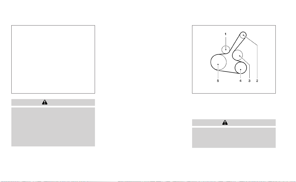
CAUTION
• Do not ground accessories directly to
the battery terminal. Doing so will
bypass the variable voltage control
system and the vehicle battery may
not charge completely.
• Use electrical accessories with the
engine running to avoid discharging
the vehicle battery.
Your vehicle is equipped with a variable
voltage control system. This system mea-
sures the amount of electrical discharge
from the battery and controls voltage gen-
erated by the generator.
The current sensor is located near the bat-
tery along the negative battery cable. If you
add electrical accessories to your vehicle,
be sure to ground them to a suitable body
ground such as the frame or engine block
area.
1. Automatic tensioner pulley
2. Generator pulley
3. Water pump pulley
4. Air conditioner compressor pulley
5. Crankshaft pulley
WARNING
Be sure the ignition switch is in the OFF
or LOCK position before servicing drive
belt. The engine could rotate
unexpectedly.
LDI3272 WDI0638
VARIABLE VOLTAGE CONTROL
SYSTEM
DRIVE BELT
8-16 Do-it-yourself
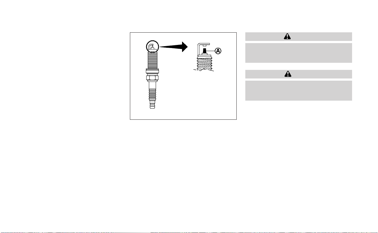
1. Visually inspect the belt for signs of un-
usual wear, cuts, or fraying. If the belt is in
poor condition, have it replaced. It is rec-
ommended that you visit a NISSAN
dealer for this service.
2. Have the belt checked regularly for
condition.
REPLACING SPARK PLUGS
Iridium-tipped spark plugs
It is not necessary to replace iridium-
tipped
O
A
spark plugs as frequently as con-
ventional type spark plugs because they
last much longer. Follow the maintenance
log shown in the “Maintenance and sched-
ules” (P. 9-2). Do not service iridium-tipped
spark plugs by cleaning or regapping.
• Always replace spark plugs with rec-
ommended or equivalent ones.
WARNING
Be sure the engine and ignition switch
are off and that the parking brake is
engaged securely.
CAUTION
Be sure to use the correct socket to re-
move the spark plugs. An incorrect
socket can damage the spark plugs.
If replacement is required, it is recom-
mended that you visit a NISSAN dealer for
this service.
SDI1895
SPARK PLUGS
Do-it-yourself 8-17

NOTE:
The air cleaner filter should not be
cleaned and reused.
Replace the air cleaner filter according to
the maintenance log shown in the ”Mainte-
nance and schedules” (P. 9-2).
To remove the air cleaner filter:
• Unlatch the clips and move the air
cleaner cover upward.
• Remove the air cleaner filter.
• Wipe the inside of the air cleaner filter
housing and the cover with a damp cloth.
The viscous paper type filter element (if so
equipped) should not be cleaned and re-
used. The dry paper type filter element (if so
equipped) may be cleaned and reused. Re-
place the air filter according to the mainte-
nance log shown in the “Maintenance and
schedules” (P. 9-2).
NOTE:
After installing a new air cleaner filter,
make sure the air cleaner cover is seated
in the housing and latch the clips.
WARNING
• Operating the engine with the air
cleaner removed can cause you or
others to be burned. The air cleaner
not only cleans the air, it stops the
flame if the engine backfires. If it isn't
there, and the engine backfires, you
could be burned. Do not drive with
the air cleaner removed, and be care-
ful when working on the engine with
the air cleaner removed.
• Never pour fuel into the throttle body
or attempt to start the engine with
the air cleaner removed. Doing so
could result in serious injury.
IN-CABIN MICROFILTER
The in-cabin microfilter restricts the entry
of airborne dust and pollen particles and
reduces some objectionable outside
odors. The filter is located behind the glove
box. For additional information, see "Main-
tenance and schedules" (P. 9-2) for change
intervals.
If replacement is required, it is recom-
mended that you visit a NISSAN dealer for
this service.
LDI3273
AIR CLEANER
8-18 Do-it-yourself

CLEANING
If your windshield is not clear after using
the windshield–washer or if a wiper blade
chatters when running, wax or other mate-
rial may be on the blade or windshield.
Clean the outside of the windshield with a
washer fluid or a mild detergent.Your wind-
shield is clean if beads do not form when
rinsing with clear water.
Clean each blade by wiping it with a cloth
soaked in a washer fluid or a mild deter-
gent. Then rinse the blades with clear wa-
ter. If your windshield is still not clear after
cleaning the blades and using the wiper,
install new windshield wiper blades.
CAUTION
Worn windshield wiper blades can
damage the windshield and impair
driver vision.
REPLACING
Replace the wiper blades if they are worn.
To replace the windshield wiper blades, fol-
low the procedure below:
1. Lift the wiper arm away from the
windshield.
2. Push the release tab
O
B
.
3. Move the wiper blade
O
A
down and
remove.
4. Insert the new wiper blade onto the
wiper arm until it clicks into place.
5. Push wiper on to windshield.
CAUTION
• After wiper blade replacement, re-
turn the wiper arm to its original po-
sition; otherwise it may be damaged
when the hood is opened.
• Make sure the wiper blades contact
the glass; otherwise the arms may be
damaged from wind pressure.
LDI2757
WINDSHIELD WIPER BLADES
Do-it-yourself 8-19

If you wax the surface of the hood, be care-
ful not to let wax get into the washer nozzle
O
D
. This may cause clogging or improper
windshield-washer operation. If wax gets
into the nozzle, remove it with a needle or
small pin
O
C
.
If the brakes do not operate properly, have
the brakes checked. It is recommended
that you visit a NISSAN dealer for this
service.
Self-adjusting brakes
Your vehicle is equipped with self-adjusting
brakes.
The front and rear disc-type brakes self-
adjust every time the brake pedal is
applied.
WARNING
Have your brake system checked if the
brake pedal height does not return to
normal. It is recommended that you
visit a NISSAN dealer for this service.
Brake pad wear indicators
The disc brake pads on your vehicle have
audible wear indicators. When a brake pad
requires replacement, a high pitched
scraping or screeching sound will be heard
when the vehicle is in motion. The noise will
be heard whether or not the brake pedal is
depressed. Have the brakes checked as
soon as possible if the wear indicator
sound is heard.
Under some driving or climate conditions,
occasional brake squeak, squeal or other
noise may be heard. Occasional brake
noise during light to moderate stops is nor-
mal and does not affect the function or
performance of the brake system.
Proper brake inspection intervals should
be followed. For additional information re-
garding brake inspections, see the appro-
priate maintenance schedule information
in the "Maintenance and schedules" (P. 9-2).
LDI2731
BRAKES
8-20 Do-it-yourself

If any electrical equipment does not oper-
ate, check for an open fuse.
Fuses are used in the passenger and en-
gine compartment. Spare fuses are pro-
vided and can be found in the passenger
compartment fuse box.
When installing a fuse make sure the fuse is
installed in the fuse box securely.
ENGINE COMPARTMENT
WARNING
Never use a fuse of a higher or lower
amperage rating than that specified on
the fuse box cover. This could damage
the electrical system or electronic con-
trol units or cause a fire.
If any electrical equipment does not come
on, check for an open fuse.
1. Be sure the ignition switch and the head-
light switch are OFF.
2. Open the engine hood.
3. Remove the fuse box cover by pushing
the tab and lifting the cover up.
4. Remove the fuse with the fuse puller.
The fuse puller is located in the center of
the fuse block in the passenger
compartment.
LDI2997 LDI3274
FUSES
Do-it-yourself 8-21

5. If the fuse is open
O
A
, replace it with a
new fuse
O
B
.
6. If a new fuse also opens, have the elec-
trical system checked and repaired. It is
recommended that you visit a NISSAN
dealer for this service.
Fusible links
If the electrical equipment does not oper-
ate and fuses are in good condition, check
the fusible links. If any of these fusible links
are melted, replace with only Genuine
NISSAN parts.
PASSENGER COMPARTMENT
WARNING
Never use a fuse of higher or lower am-
perage rating than that specified on
the fuse box cover. This could damage
the electrical system or electronic con-
trol units or cause a fire.
If any electrical equipment does not oper-
ate, check for an open fuse.
1. Be sure the ignition switch and the head-
light switch are in the OFF position.
2. Remove the fuse box cover
O
A
with a
suitable tool. Use a cloth to avoid dam-
aging the trim.
LDI3200 LDI3275
8-22 Do-it-yourself

3. Remove the fuse with the fuse puller
O
B
. 4. If the fuse is open
O
C
, replace it with an
equivalent good fuse
O
D
.
5. Push the fuse box cover to install.
6. If a new fuse also opens, have the elec-
trical system checked and repaired. It is
recommended that you visit a NISSAN
dealer for this service.
CAUTION
Be careful not to allow children to swal-
low the battery or removed parts.
LDI3276 LDI3203
BATTERY REPLACEMENT
Do-it-yourself 8-23
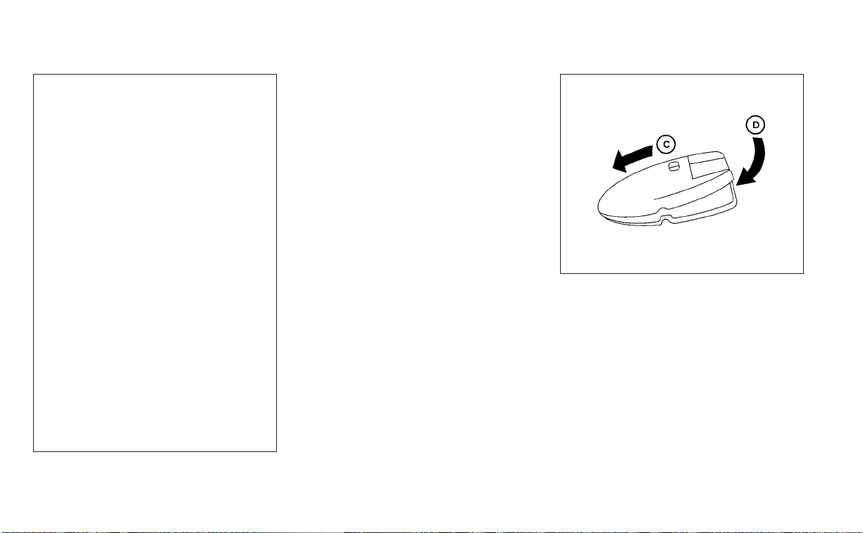
NISSAN INTELLIGENT KEY®
Replace the battery in the Intelligent Key as
follows:
1. Remove the mechanical key from the
Intelligent Key.
2. Insert a small screwdriver
O
A
into the slit
O
B
of the corner and twist it to separate
the upper part from the lower part. Use a
cloth to protect the casing.
3. Replace the battery with a new one.
Recommended battery: CR2032 or
equivalent.
• Do not touch the internal circuit and
electric terminals as doing so could
cause a malfunction.
• Hold the battery by the edges. Holding
the battery across the contact points
will seriously deplete the storage
capacity.
• Make sure that the + side faces the
bottom of the lower part.
4. Close the lid securely as illustrated with
O
C
and
O
D
.
5. Operate the buttons to check the
operation.
It is recommended that you visit a NISSAN
dealer for this service if you need assis-
tance for replacement.
LDI2001
WDI0568
8-24 Do-it-yourself

FCC Notice:
For USA:
This device complies with Part 15 of the
FCC Rules. Operation is subject to the fol-
lowing two conditions: (1) This device
may not cause harmful interference, and
(2) this device must accept any interfer-
ence received, including interference
that may cause undesired operation.
NOTE:
Changes or modifications not expressly
approved by the party responsible for
compliance could void the user’s author-
ity to operate the equipment.
For Canada:
This device contains licence-exempt
transmitter(s)/receiver(s) that comply
with Innovation, Science and Economic
Development Canada’s licence-exempt
RSS(s). Operation is subject to the fol-
lowing two conditions: (1) This device
may not cause interference. (2) This de-
vice must accept any interference, in-
cluding interference that may cause un-
desired operation of the device.
HEADLIGHTS
For additional information on headlight
bulb replacement, refer to the instructions
outlined in this section.
Replacing the halogen headlight
bulb (if so equipped)
The headlight is a semi-sealed beam type
which uses a replaceable headlight (halo-
gen) bulb. They can be replaced from inside
the engine compartment without remov-
ing the headlight assembly.
If headlight bulb replacement is required, it
is recommended that you visit a NISSAN
dealer for this service.
CAUTION
• Aiming is not necessary after replac-
ing the bulb. When aiming adjust-
ment is necessary, it is recom-
mended that you visit a NISSAN
dealer for this service.
• Do not leave the headlight assembly
open without a bulb installed for a
long period of time. Dust, moisture,
smoke, etc. entering the headlight
body may affect bulb performance.
Remove the bulb from the headlight
assembly just before a replacement
bulb is installed.
• Only touch the base when handling
the bulb. Never touch the glass enve-
lope. Touching the glass could sig-
nificantly affect bulb life and/or
headlight performance.
• High pressure halogen gas is sealed
inside the halogen bulb. The bulb
may break if the glass envelope is
scratched or the bulb is dropped.
• Use the same number and wat tage
as shown in the chart.
Fog may temporarily form inside the lens
of the exterior lights in the rain or in a car
wash. A temperature difference between
the inside and the outside of the lens
causes the fog. This is not a malfunction. If
large drops of water collect inside the lens,
it is recommended that you visit a NISSAN
dealer for this service.
LIGHTS
Do-it-yourself 8-25

Replacing the LED headlight bulb
(if so equipped)
If LED headlight bulb replacement is re-
quired, it is recommended that you visit a
NISSAN dealer for this service.
FOG LIGHTS (if so equipped)
For additional information on fog light bulb
replacement, refer to the instructions out-
lined in this section.
Replacing the LED fog light bulb
If LED fog light bulb replacement is re-
quired, it is recommended that you visit a
NISSAN dealer for this service.
EXTERIOR AND INTERIOR LIGHTS
Item Wattage (W) Bulb No.*
Headlight assembly (Type A) (if so equipped*)
Low (Halogen) 55 H11
High (Halogen) 60 HB3
Side marker 5 W5W
Headlight assembly (Type B) (if so equipped)*
Low/High — —
Park/Daytime running — —
Side marker — —
Fog light (if so equipped)* — —
Turn signal/park (if so equipped) light* 28/8 7444NA
Door mirror turn signal light (if so equipped)* — —
Step light (if so equipped) 3.8 194
Map light* 8 —
Vanity mirror light* 1.8 —
Courtesy light (if so equipped)* — —
Glove box light* 1 —
Personal light* 8 —
Trunk light 3.4 158
High-mounted stop light* — —
Rear combination light*
Stop/Tail 21/5 W21/5W
Turn 21 W21W
Side marker 5 W5W
Backup (reversing) assembly*
Backup 16 921
Tail 5 W5W
License plate light* 5 —
* It is recommended that you visit a NISSAN dealer for replacement.
Always check with the Parts Department at a NISSAN dealer for the latest parts
information.
8-26 Do-it-yourself

1. Headlight assembly
2. Map light
3. Door mirror turn signal light
(if so equipped)
4. Step light (if so equipped)
5. Turn signal/park (if so equipped) light
6. Fog light (if so equipped)
7. Personal light
8. High-mount stop light
9. Trunk light
10. License plate light
11. Backup (reversing) assembly
12. Rear combination light
LDI3277
Do-it-yourself 8-27
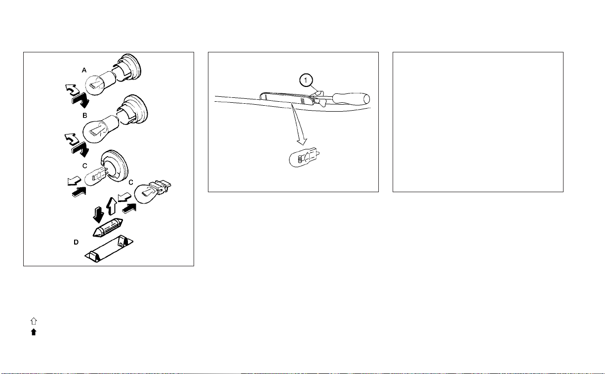
Replacement procedures
All other lights are either type A, B, C or D.
When replacing a bulb, first remove the
lens, light and/or cover.
Indicates bulb removal
Indicates bulb installation
Use a cloth
O
1
to protect the housing.
Rear combination light
Bulb replacement requires the removal of
the rear combination light assembly. If re-
placement is required, it is recommended
that you visit a NISSAN dealer for this
service.
WDI0306
LDI0341
Step light (if so equipped)
LDI2135
Trunk light
8-28 Do-it-yourself

If you have a flat tire, see “Flat tire”
(P. 6-3).
TIRE PRESSURE
Tire Pressure Monitoring System
(TPMS)
WARNING
Radio waves could adversely af-
fect electric medical equipment.
Those who use a pacemaker
should contact the electric medi-
cal equipment manufacturer for
the possible influences before
use.
This vehicle is equipped with the Tire
Pressure Monitoring System (TPMS).
It monitors tire pressure of all tires
except the spare. When the low tire
pressure warning light is lit and the
“Tire Pressure Low - Add Air” warning
appears in the vehicle information
display, one or more of your tires is
significantly under-inflated.
The TPMS will activate only when the
vehicle is driven at speeds above 16
mph (25 km/h). Also, this system
may not detect a sudden drop in tire
pressure (for example a flat tire while
driving).
For additional information, see “Low
tire pressure warning light” (P. 2-13),
“Tire Pressure Monitoring System
(TPMS)” (P. 5-5), and “Flat tire” (P. 6-3).
Tire inflation pressure
Check the tire pressures (including
the spare) often and always prior to
long distance trips. The recom-
mended tire pressure specifications
are shown on the F.M.V.S.S./C.M.V.S.S.
certification label or the Tire and
Loading Information label under the
"Cold Tire Pressure" heading. The
Tire and Loading Information label is
affixed to the driver side center pillar.
Tire pressures should be checked
regularly because:
• Most tires naturally lose air over
time.
• Tires can lose air suddenly when
driven over potholes or other ob-
jects or if the vehicle strikes a curb
while parking.
The tire pressures should be
checked when the tires are cold. The
tires are considered COLD after the
vehicle has been parked for 3 or
more hours, or driven less than 1 mile
(1.6 km) at moderate speeds.
The TPMS with Easy-Fill Tire Alert
provides visual and audible signals
outside the vehicle for inflating the
tires to the recommended COLD tire
pressure. For additional information,
see “TPMS with Easy-Fill Tire Alert”
(P. 5-8).
WHEELS AND TIRES
Do-it-yourself 8-29

If the tires are used at speeds above
100 mph (162 km/h) where it is legal
to do so (on a race track for ex-
ample), the cold tire inflation pres-
sure must be increased. For addi-
tional information, see “Checking tire
pressure” (P. 8-32).
Set the tire pressure to the normal
cold tire inflation pressure when the
vehicle speed or load is reduced.
Incorrect tire pressure, including
under inflation, may adversely af-
fect tire life and vehicle handling.
WARNING
• Improperly inflated tires can
fail suddenly and cause an
accident.
• The Gross Vehicle Weight Rat-
ing (GVWR) is located on the
F.M.V.S.S./C.M.V.S.S. certifica-
tion label. The vehicle weight
capacity is indicated on the Tire
and Loading Information label.
Do not load your vehicle be-
yond this capacity. Overload-
ing your vehicle may result in
reduced tire life, unsafe operat-
ing conditions due to prema-
ture tire failure, or unfavorable
handling characteristics and
could also lead to a serious ac-
cident. Loading beyond the
specified capacity may also re-
sult in failure of other vehicle
components.
• Before taking a long trip, or
whenever you heavily load
your vehicle, use a tire pressure
gauge to ensure that the tire
pressures are at the specified
level.
• Increase the cold tire inflation
pressure as indicated in
"Checking tire pressure"
(P. 8-32) when using the tires
specified by NISSAN above 100
mph (162 km/h) where it is le-
gal to do so (on a race track for
example). Failure to increase
the cold tire inflation pressure
may result in tire failure, loss of
control and possible injury. Af-
ter such use, readjust tire
pressure.
• For additional information re-
garding tires, refer to “Impor-
tant Tire Safety Information”
(US) or “Tire Safety Informa-
tion” (Canada) in the Warranty
Information Booklet.
8-30
Do-it-yourself

Tire and Loading Information
label
䊊
1
Seating capacity: The maximum
number of occupants that can
be seated in the vehicle.
䊊
2
Tire size – see “Tire labeling”
(P. 8-33).
䊊
3
Cold tire pressure: Inflate the tires
to this pressure when the tires
are cold. Tires are considered
COLD after the vehicle has been
parked for 3 or more hours, or
driven less than 1 mile (1.6 km) at
moderate speeds. The recom-
mended cold tire inflation is set
by the manufacturer to provide
the best balance of tire wear, ve-
hicle handling, driveability, tire
noise, etc., up to the vehicle's
GVWR.
䊊
4
Original tire size: The size of the
tires originally installed on the ve-
hicle at the factory.
䊊
5
Spare tire size.
䊊
6
Vehicle load limit: see “Vehicle
loading information” (P. 10-16).
LDI2737
Do-it-yourself 8-31

Checking tire pressure
1. Remove the valve stem cap from
the tire.
2. Press the pressure gauge
squarely onto the valve stem. Do
not press too hard or force the
valve stem sideways, or air will es-
cape. If the hissing sound of air
escaping from the tire is heard
while checking the pressure, re-
position the gauge to eliminate
this leakage.
3. Remove the gauge.
4. Read the tire pressure on the
gauge stem and compare to the
specification shown on the Tire
and Loading Information label.
5. Add air to the tire as needed. If too
much air is added, press the core
of the valve stem briefly with the
tip of the gauge stem to release
pressure. Recheck the pressure
and add or release air as needed.
6. Install the valve stem cap.
7. Check the pressure of all other
tires, including the spare.
Size Cold Tire
Inflation
Pressure
Front and
Rear
Original
Tire
215/60R16
220 kPa,
32 PSI
215/55R17
230 kPa,
33 PSI
235/40R19
230 kPa,
33 PSI
Spare Tire
T135/90D16
420 kPa,
60 PSI
T135/70D16
420 kPa,
60 PSI
LDI0393
8-32 Do-it-yourself
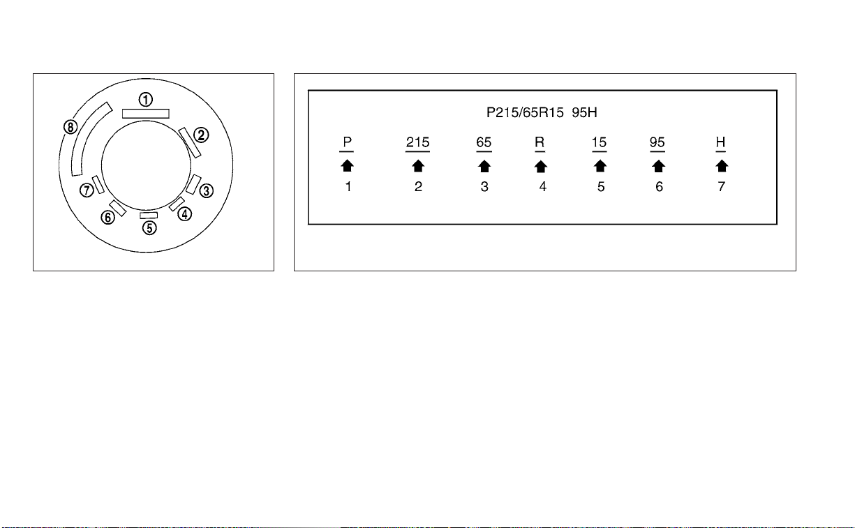
TIRE LABELING
Federal law requires tire manufac-
turers to place standardized infor-
mation on the sidewall of all tires.
This information identifies and de-
scribes the fundamental character-
istics of the tire and also provides the
Tire Identification Number (TIN) for
safety standard certification. The TIN
can be used to identify the tire in
case of a recall.
O
1
Tire size (example: P215/65R15
95H)
1. P: The “P” indicates the tire is de-
signed for passenger vehicles (not
all tires have this information).
2. Three-digit number (215): This
number gives the width in milli-
meters of the tire from sidewall
edge to sidewall edge.
3. Two-digit number (65): This num-
ber, known as the aspect ratio,
gives the tire's ratio of height to
width.
4. R: The “R” stands for radial.
5. Two-digit number (15): This num-
ber is the wheel or rim diameter in
inches.
WDI0394
Example
WDI0395
Example
Do-it-yourself 8-33

6. Two- or three-digit number (95):
This number is the tire's load in-
dex. It is a measurement of how
much weight each tire can
support.
7. H: Tire speed rating. You should
not drive the vehicle faster than
the tire speed rating.
O
2
TIN (Tire Identification Number)
for a new tire (example: DOT XX XX
XXX XXXX)
1. DOT: Abbreviation for the “Depart-
ment Of Transportation”. The
symbol can be placed above, be-
low or to the left or right of the Tire
Identification Number.
2. Two-digit code: Manufacturer's
identification mark.
3. Two-digit code: Tire size.
4. Three-digit code: Tire type code
(Optional).
5. Four numbers represent the
week and year the tire was built.
For example, the numbers 3103
means the 31st week of 2003. If
these numbers are missing then
look on the other sidewall of the
tire.
LDI2786
Example
8-34 Do-it-yourself

O
3
Tire ply composition and material
The number of layers or plies of
rubber-coated fabric in the tire. Tire
manufacturers also must indicate
the materials in the tire, which in-
clude steel, nylon, polyester and
others.
O
4
Maximum permissible inflation
pressure
This number is the greatest amount
of air pressure that should be put in
the tire.Do not exceed the maximum
permissible inflation pressure.
O
5
Maximum load rating
This number indicates the maxi-
mum load in kilograms and pounds
that can be carried by the tire. When
replacing the tires on the vehicle, al-
ways use a tire that has the same
load rating as the factory installed
tire.
O
6
Term of “tubeless” or “tube type”
Indicates whether the tire requires
an inner tube (“tube type”) or not
(“tubeless”).
O
7
The word “radial”
The word “radial” is shown if the tire
has radial structure.
O
8
Manufacturer or brand name
Manufacturer or brand name is
shown.
Other Tire-related Terminology
In addition to the many terms that
are defined throughout this section,
Intended Outboard Sidewall is (1) the
sidewall that contains a whitewall,
bears white lettering or bears
manufacturer, brand, and/or model
name molding that is higher or
deeper than the same molding on
the other sidewall of the tire, or (2)
the outward facing sidewall of an
asymmetrical tire that has a particu-
lar side that must always face out-
ward when mounted on a vehicle.
TYPES OF TIRES
WARNING
• When changing or replacing tires, be
sure all four tires are of the same type
(i.e., Summer, All Season or Snow)
and construction. A NISSAN dealer
may be able to help you with infor-
mation about tire type, size, speed
rating and availability.
• Replacement tires may have a lower
speed rating than the factory
equipped tires, and may not match
the potential maximum vehicle
speed. Never exceed the maximum
speed rating of the tire.
• Replacing tires with those not origi-
nally specified by NISSAN could af-
fect the proper operation of the low
tire pressure warning system.
Do-it-yourself 8-35

• Always use tires of the same type,
size, brand, construction and tread
pattern on all four wheels. Failure to
do so may result in a circumference
difference between tires on the front
and rear axles which can cause the
Vehicle Dynamic Control (VDC) sys-
tem to malfunction resulting in per-
sonal injury or death, excessive tire
wear and may damage the transmis-
sion and differential gears.
• For additional information regarding
tires, refer to “Important Tire Safety
Information” (US) or “Tire Safety In-
formation” (Canada) in the Warranty
Information Booklet.
All-Wheel Drive (AWD) models
WARNING
For AWD vehicles - the TEMPORARY USE
ONLY spare tire must be installed to the
rear wheels only. If a front tire is punc-
tured, install the original rear tire onto
the front wheel, then install the TEMPO-
RARY USE ONLY spare tire on the rear.
Failure to do so could cause overheat-
ing to the AWD system
CAUTION
• ONLY use spare tires specified for the
AWD model.
If excessive tire wear is found, it is recom-
mended that all four tires be replaced with
tires of the same size, brand, construction
and tread pattern. The tire pressure and
wheel alignment should also be checked
and corrected as necessary. It is recom-
mended that you visit a NISSAN dealer for
this service.
All season tires
NISSAN specifies All Season tires on some
models to provide good performance all
year, including snowy and icy road condi-
tions. All Season tires are identified by ALL
SEASON and/or M&S on the tire sidewall.
Snow tires have better snow traction than
All Season tires and may be more appropri-
ate in some areas.
Summer tires
NISSAN specifies summer tires on some
models to provide superior performance
on dry roads. Summer tire per formance is
substantially reduced in snow and ice.
Summer tires do not have the tire traction
rating “M&S” on the tire sidewall.
If you plan to operate your vehicle in snowy
or icy conditions, NISSAN recommends the
use of SNOW tires or ALL SEASON tires on all
four wheels.
Snow tires
If snow tires are needed, it is necessary to
select tires equivalent in size and load rat-
ing to the original equipment tires. If you do
not, it can adversely affect the safety and
handling of your vehicle.
Generally, snow tires have lower speed rat-
ings than factory equipped tires and may
not match the potential maximum vehicle
speed. Never exceed the maximum speed
rating of the tire.
If you install snow tires, they must be the
same size, brand, construction and tread
pattern on all four wheels.
For additional traction on icy roads, stud-
ded tires may be used. However, some U.S.
states and Canadian provinces prohibit
their use. Check local, state and provincial
laws before installing studded tires. Skid
and traction capabilities of studded snow
tires on wet or dry surfaces may be poorer
than that of non-studded snow tires.
8-36 Do-it-yourself
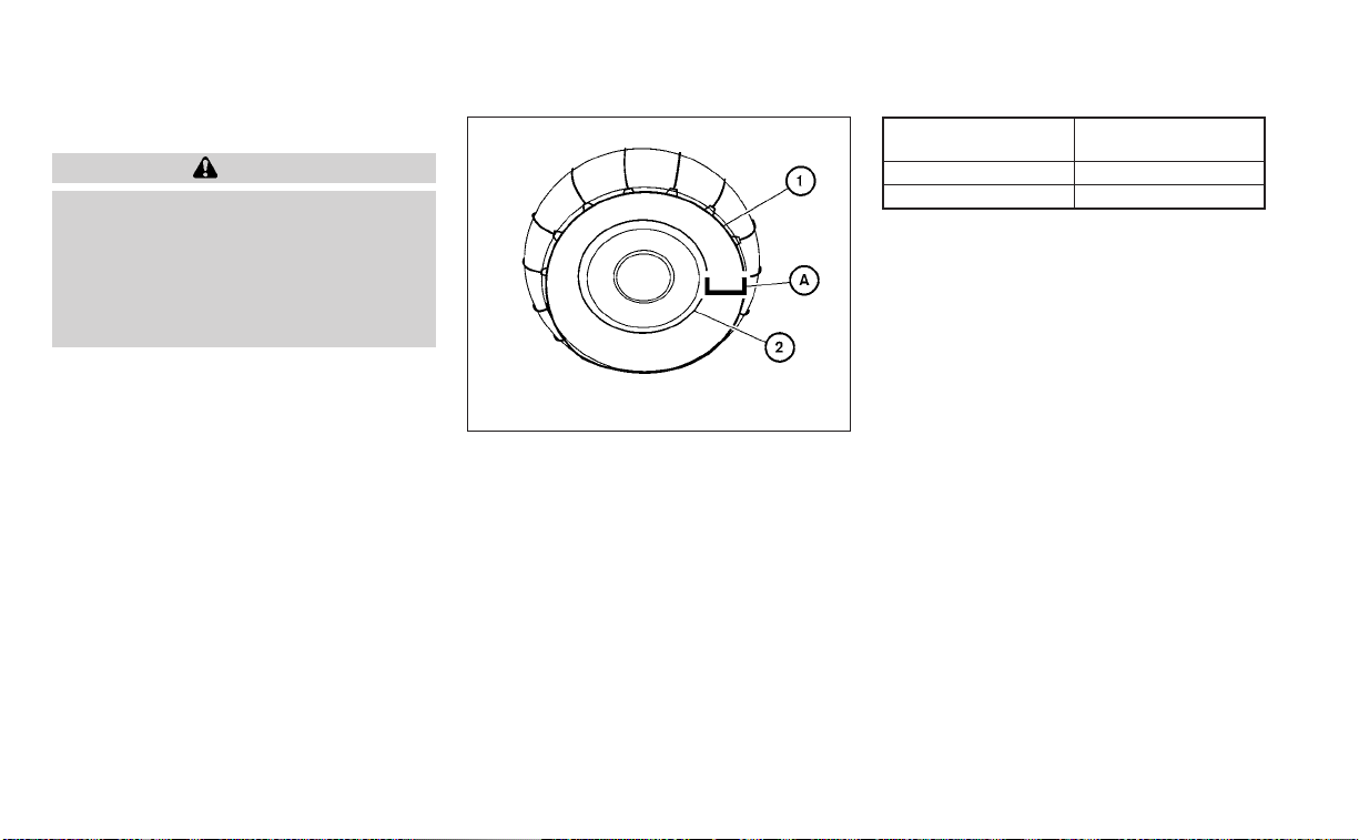
TIRE CHAINS
CAUTION
Only certain SAE class “S” tire chains
can be used on this vehicle. Using the
wrong Class “S” chains on this vehicle
will cause damage to the vehicle. If you
plan to use tire chains/cables, you
should use a tire chain that meets the
minimum clearances for your vehicle.
Use of tire chains may be prohibited ac-
cording to location. Check the local laws
before installing tire chains. When installing
tire chains, make sure they are the proper
size for the tires on your vehicle and are
installed according to the chain manufac-
turer's suggestions. Use a tire chain that is
designed to provide the specified space
O
A
between the installed tire chain
O
1
and
where the tire meets the rim
O
2
as shown
on the chart.
NOTE:
Tire chains are not permitted for use
with 19 in wheels.
Wheel size Minimum space re-
quired
16 in .7 in (17 mm)
17 in .2 in (4 mm)
A tire chain that provides the specified
amount of space will provide the neces-
sary clearance between the tire and the
closest vehicle suspension or body com-
ponent. The minimum clearances are de-
termined using the factory-equipped tires.
Other types may damage your vehicle. Use
chain tensioners when recommended by
the tire chain manufacturer to ensure a
tight fit. Loose end links of the tire chain
must be secured or removed to prevent
the possibility of whipping action damage
to the fenders or underbody. If possible,
avoid fully loading your vehicle when using
tire chains. In addition, drive at a reduced
speed. Otherwise, your vehicle may be
damaged and/or vehicle handling and
performance may be adversely affected.
Tire chains must be installed only on the
front wheels and not on the rear wheels.
Never install tire chains on a TEMPORARY
USE ONLY spare tire.
LDI0574
Do-it-yourself 8-37
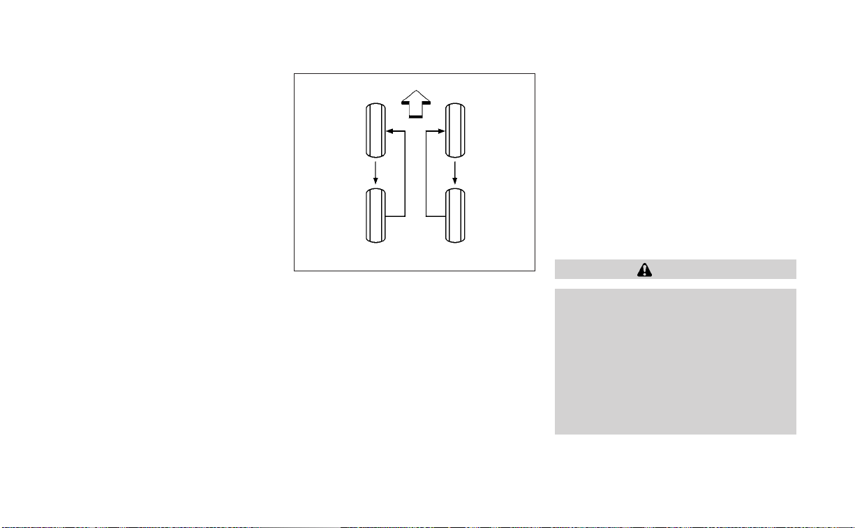
Do not use tire chains on dry roads. Driving
with tire chains in such conditions can
cause damage to the various mechanisms
of the vehicle due to some overstress.
CHANGING WHEELS AND TIRES
Tire rotation
NISSAN recommends rotating the
tires every 5,000 miles (8,000 km) for
vehicles equipped with the 2.5L 4 cyl-
inder (PR25DD engine model) and
7,500 miles (12,000 km) for vehicles
equipped with the 2.0L 4 cylinder
(KR20DDET engine model).
For additional information on tire re-
placing procedures, “Flat tire” (P. 6-3).
As soon as possible, tighten the
wheel nuts to the specified torque
with a torque wrench.
Wheel nut tightening torque:
83 ft-lb (113 N·m)
The wheel nuts must be kept tight-
ened to specifications at all times.
It is recommended that wheel nuts
be tightened to specification at
each tire rotation interval.
WARNING
• After rotating the tires, check
and adjust the tire pressure.
• Retighten the wheel nuts when
the vehicle has been driven for
600 miles (1,000 km) (also in
cases of a flat tire, etc.).
• Do not include the spare tire in
the tire rotation.
WDI0258
8-38 Do-it-yourself
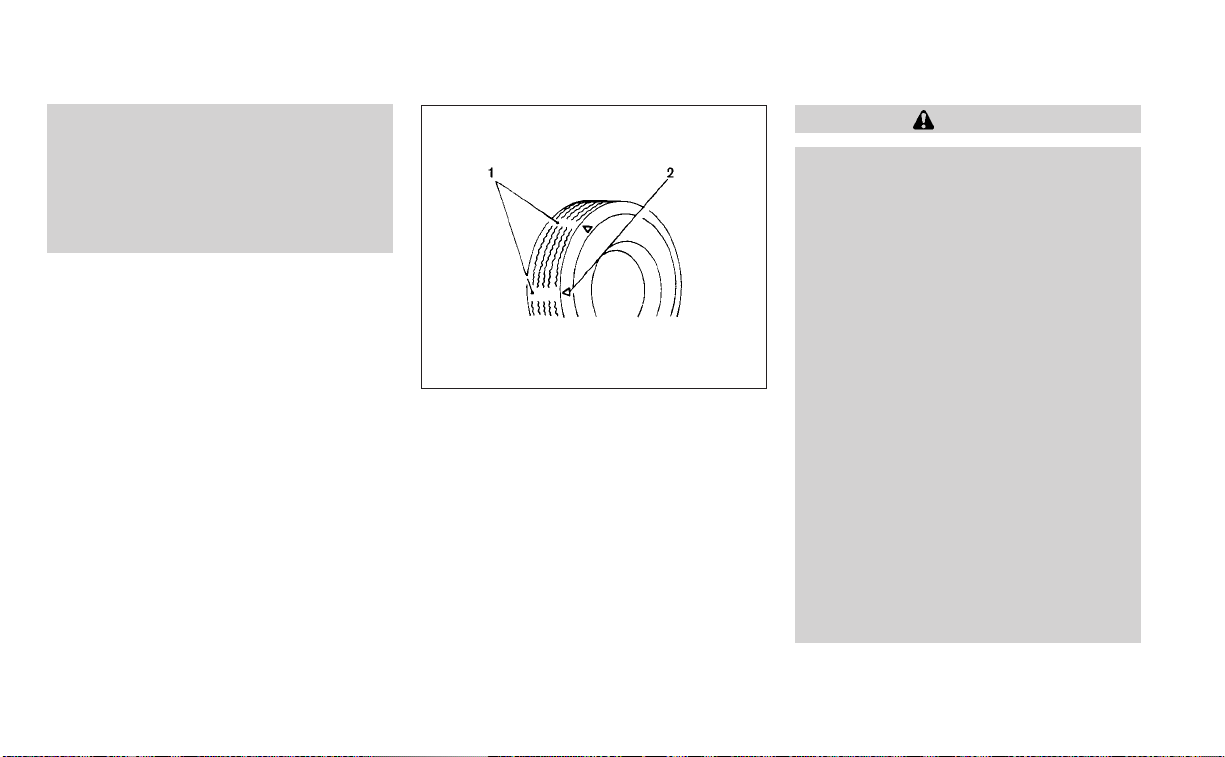
• For additional information re-
garding tires, refer to “Impor-
tant Tire Safety Information”
(US) or “Tire Safety Informa-
tion” (Canada) in the Warranty
Information Booklet.
Tire wear and damage
1. Wear indicator
2. Location mark
WARNING
• Tires should be periodically in-
spected for wear, cracking,
bulging or objects caught in
the tread. If excessive wear,
cracks, bulging or deep cuts
are found, the tire(s) should be
replaced.
• The original tires have built-in
tread wear indicators. When
the wear indicators are visible,
the tire(s) should be replaced.
• Tires degrade with age and
use. Have tires, including the
spare, over 6 years old checked
by a qualified technician be-
cause some tire damage may
not be obvious. Replace the
tires as necessary to prevent
tire failure and possible per-
sonal injury.
WDI0259
Do-it-yourself 8-39

• Improper service of the spare
tire may result in serious per-
sonal injury. If it is necessary to
repair the spare tire, it is rec-
ommended that you visit a
NISSAN dealer for this service.
• For additional information re-
garding tires, refer to “Impor-
tant Tire Safety Information”
(US) or “Tire Safety Informa-
tion” (Canada) in the Warranty
Information Booklet.
Replacing wheels and tires
When replacing a tire, use the same size,
tread design, speed rating and load carry-
ing capacity as originally equipped. For ad-
ditional information, see “Wheels and tires”
(P. 8-29).
WARNING
• The use of tires other than those rec-
ommended or the mixed use of tires
of different brands, construction
(bias, bias-belted or radial), or tread
patterns can adversely affect the
ride, braking, handling, Vehicle Dy-
namic Control (VDC) system, ground
clearance, body-to-tire clearance,
tire chain clearance, speedometer
calibration, headlight aim and bum-
per height. Some of these effects
may lead to accidents and could re-
sult in serious personal injury.
• If your vehicle was originally
equipped with four tires that were
the same size and you are only re-
placing two of the four tires, install
the new tires on the rear axle. Placing
new tires on the front axle may cause
loss of vehicle control in some driving
conditions and cause an accident
and personal injury.
• If the wheels are changed for any
reason, always replace with wheels
which have the same off-set dimen-
sion. Wheels of a different off-set
could cause premature tire wear, de-
grade vehicle handling characteris-
tics, affect the VDC system and/or in-
ter ference with the brake discs. Such
inter ference can lead to decreased
braking efficiency and/or early brake
pad wear. For additional information
on wheel off-set dimensions, see
“Wheels and tires” (P. 8-29).
• When using a wheel without the
TPMS, such as the spare tire, the
TPMS will not function and the low
tire pressure warning light will flash
for approximately 1 minute. The light
will remain on after 1 minute. Have
your tires replaced and/or TPMS sys-
tem reset as soon as possible. It is
recommended that you visit a
NISSAN dealer for this service.
• Replacing tires with those not origi-
nally specified by NISSAN could af-
fect the proper operation of the
TPMS.
• The TPMS sensor may be damaged if
it is not handled correctly. Be careful
when handling the TPMS sensor.
8-40 Do-it-yourself

• When replacing the TPMS sensor, the
ID registration may be required. It is
recommended that you visit a
NISSAN dealer for ID registration.
• Do not use a valve stem cap that is
not specified by NISSAN. The valve
stem cap may become stuck.
• Be sure that the valve stem caps are
correctly fitted. Otherwise the valve
may be clogged up with dirt and
cause a malfunction or loss of
pressure.
• Do not install a damaged or de-
formed wheel or tire even if it has
been repaired. Such wheels or tires
could have structural damage and
could fail without warning.
• The use of retread tires is not
recommended.
• For additional information regarding
tires, refer to “Important Tire Safety
Information” (US) or “Tire Safety In-
formation” (Canada) in the Warranty
Information Booklet.
Wheel balance
Unbalanced wheels may affect vehicle
handling and tire life. Even with regular use,
wheels can get out of balance. Therefore,
they should be balanced as required.
Wheel balance service should be per-
formed with the wheels off the vehicle.
Spin balancing the wheels on the vehicle
could lead to mechanical damage.
• For additional information regarding
tires, refer to “Important Tire Safety In-
formation” (US) or “Tire Safety Informa-
tion” (Canada) in the Warranty Informa-
tion Booklet.
Care of wheels
• Wash the wheels when washing the ve-
hicle to maintain their appearance.
• Clean the inner side of the wheels when
the wheel is changed or the underside of
the vehicle is washed.
• Do not use abrasive cleaners when
washing the wheels.
• Inspect wheel rims regularly for dents or
corrosion. Such damage may cause loss
of pressure or poor seal at the tire bead.
• NISSAN recommends waxing the road
wheels to protect against road salt in ar-
eas where it is used during winter.
Spare tire (TEMPORARY USE ONLY
spare tire)
When using a wheel without the TPMS such
as the spare tire, the TPMS will not function.
Observe the following precautions if the
TEMPORARY USE ONLY spare tire must be
used. Otherwise, your vehicle could be
damaged or involved in an accident:
WARNING
• For AWD vehicles - the TEMPORARY
USE ONLY spare tire must be installed
to the rear wheels only. If a front tire
is punctured, install the original rear
tire onto the front wheel, then install
the TEMPORARY USE ONLY spare tire
on the rear. Failure to do so could
cause overheating to the AWD
system
• The spare tire should be used for
emergency use only. It should be re-
placed with the standard tire at the
first opportunity to avoid possible
tire or differential damage.
• Drive carefully while the TEMPORARY
USE ONLY spare tire is installed. Avoid
sharp turns and abrupt braking while
driving.
Do-it-yourself 8-41

• Periodically check spare tire inflation
pressure. Always keep the pressure
of the TEMPORARY USE ONLY spare
tire at 420 kPa, 4.2 bar (60 psi).
• With the TEMPORARY USE ONLY spare
tire installed do not drive the vehicle
at speeds faster than 50 mph (80
km/h).
• When driving on roads covered with
snow or ice, the TEMPORARY USE
ONLY spare tire should be used on the
rear wheels and the original tire used
on the front wheels (drive wheels).
• Tire tread of the TEMPORARY USE
ONLY spare tire will wear at a faster
rate than the standard tire. Replace
the spare tire as soon as the tread
wear indicators appear.
• Do not use the spare tire on other
vehicles.
• Do not use more than one spare tire
at the same time.
• Do not tow a trailer when the TEMPO-
RARY USE ONLY spare tire is installed.
CAUTION
• Do not use tire chains on a TEMPO-
RARY USE ONLY spare tire. Tire chains
will not fit properly and may cause
damage to the vehicle.
• Because the TEMPORARY USE ONLY
spare tire is smaller than the original
tire, ground clearance is reduced. To
avoid damage to the vehicle, do not
drive over obstacles. Also, do not
drive the vehicle through an auto-
matic car wash since it may get
caught.
8-42 Do-it-yourself

9 Maintenance and schedules
Maintenance requirements .....................9-2
General maintenance ........................9-2
Scheduled maintenance .....................9-2
Where to go for service .......................9-2
General maintenance ...........................9-2
Explanation of general maintenance
items ........................................9-2
Explanation of scheduled maintenance items . . . 9-5
Emission control system maintenance: ......9-6
Chassis and body maintenance: .............9-6
Maintenance schedules .........................9-7
Additional maintenance items for
severe operating conditions ..................9-7
Oil control system (if so equipped) ............9-7
2.5L 4 cylinder (PR25DD engine model) ........9-9
2.0L 4 cylinder (KR20DDET engine
model) ......................................9-28

Some day-to-day and regular mainte-
nance is essential to maintain your vehicle
good mechanical condition, as well as its
emissions and engine performance.
It is the owner's responsibility to make sure
that the scheduled maintenance, as well as
general maintenance, is performed.
As the vehicle owner, you are the only one
who can ensure that your vehicle receives
proper maintenance. You are a vital link in
the maintenance chain.
GENERAL MAINTENANCE
General maintenance includes those items
which should be checked during normal
day-to-day operation. They are essential
for proper vehicle operation. It is your re-
sponsibility to perform these procedures
regularly as prescribed.
Performing general maintenance checks
requires minimal mechanical skill and only
a few general automotive tools.
These checks or inspections can be done
by yourself, a qualified technician or, if you
prefer, a NISSAN dealer.
SCHEDULED MAINTENANCE
The maintenance items listed in this sec-
tion are required to be serviced at regular
intervals. However under severe driving
conditions, additional or more frequent
maintenance will be required.
WHERE TO GO FOR SERVICE
If maintenance service is required or your
vehicle appears to malfunction, have the
systems checked and serviced. It is recom-
mended that you visit a NISSAN dealer for
this service.
NISSAN technicians are well-trained spe-
cialists and are kept up-to-date with the
latest service information through techni-
cal bulletins, service tips and training pro-
grams. They are fully qualified to work on
NISSAN vehicles before work begins.
If your vehicle is involved in a collision, it is
recommended that you ask your NISSAN
dealer where the nearest NISSAN Certified
Collision Center is located, or go to
http://collision.nissanusa.com.
You can be confident that a NISSAN deal-
er's service department can perform the
service needed to meet the maintenance
requirements on your vehicle.
During the normal day-to-day operation of
the vehicle, general maintenance should
be performed regularly as prescribed in
this section. If you detect any unusual
sounds, vibrations or smells, be sure to
check for the cause or have it checked
promptly. In addition, it is recommended
that you visit a NISSAN dealer if you think
that repairs are required.
When performing any checks or mainte-
nance work, closely observe the “Mainte-
nance precautions” in the “Do-it-yourself”
section of this manual.
EXPLANATION OF GENERAL
MAINTENANCE ITEMS
WARNING
Failure to follow the procedures listed
within this section may result in per-
sonal injury.
Additional information on the following
items with“*”isfound in the “Do-it-
yourself” section of this manual.
MAINTENANCE REQUIREMENTS GENERAL MAINTENANCE
9-2 Maintenance and schedules

Outside the vehicle
The maintenance items listed here should
be performed from time to time, unless
otherwise specified.
Doors and engine hood: Check that the
doors and engine hood operate properly.
Also ensure that all latches lock securely.
Lubricate hinges, latches, latch pins, rollers
and links if necessary. Make sure that the
secondary latch keeps the hood from
opening when the primary latch is
released.
When driving in areas using road salt or
other corrosive materials, check lubrica-
tion frequently.
Check that the gas strays or struts properly
and securely hold the hood, trunk, or rear
hatch in the fully open position. If the hood,
trunk, or rear hatch is not held open, have
the gas stays or struts replaced.
Lights*: Clean the headlights on a regular
basis. Make sure that the headlights, stop
lights, tail lights, turn signal lights, and other
lights are all operating properly and in-
stalled securely. Also check headlight aim.
Road wheel nuts (lug nuts)*: When check-
ing the tires, make sure no wheel nuts are
missing, and check for any loose wheel
nuts. Tighten if necessary.
Tire rotation*: Rotate tires at the specified
interval shown in the maintenance
schedule.
Tires*: Check the pressure with a gauge
often and always prior to long distance
trips. If necessary, adjust the pressure in all
tires, including the spare, to the pressure
specified. Check carefully for damage, cuts
or excessive wear.
Tire Pressure Monitoring System (TPMS)
tire pressure sensor: It is recommended
that you replace the TPMS tire pressure
sensor assembly when the tires are re-
placed due to wear or age.
Wheel alignment and balance: If the ve-
hicle should pull to either side while driving
on a straight and level road, or if you detect
uneven or abnormal tire wear, there may
be a need for wheel alignment. If the steer-
ing wheel or seat vibrates at normal high-
way speeds, wheel balancing may be
needed.
For additional information regarding tires,
refer to “Important Tire Safety Information”
(US) or “Tire Safety Information” (Canada) in
the Warranty Information Booklet.
Windshield: Clean the windshield on a
regular basis. Check the windshield at least
every six months for cracks or other dam-
age. Have a damaged windshield repaired
by a qualified repair facility. It is recom-
mended that you have a damaged wind-
shield repaired by a NISSAN dealer, or a
NISSAN Certified Collision Center. To locate
a collision center in your area, refer to
http://collision.nissanusa.com.
Windshield wiper blades*: Check for
cracks or wear if they do not wipe properly.
Inside the vehicle
The maintenance items listed here should
be checked on a regular basis, such as
when performing scheduled maintenance,
cleaning the vehicle, etc.
Accelerator pedal: Check the pedal for
smooth operation and make sure the
pedal does not catch or require uneven
effort. Keep the floor mat away from the
pedal.
Brake pedal: Check the pedal for smooth
operation. If the brake pedal suddenly goes
down further than normal, the pedal feels
spongy or the vehicle seems to take longer
to stop, have your vehicle checked imme-
diately. It is recommended that you visit a
Maintenance and schedules 9-3

NISSAN dealer for this service. Keep the
floor mat away from the pedal.
Brakes: Check that the brakes do not pull
the vehicle to one side when applied.
Continuously Variable Transmission
(CVT) P (Park) position mechanism: On a
fairly steep hill check that the vehicle is held
securely with the shift lever in the P (Park)
position without applying any brakes.
Parking brake: Check the parking brake
operation regularly. The vehicle should be
securely held on a fairly steep hill with only
the parking brake applied. If the parking
brake needs adjustment, it is recom-
mended that you visit a NISSAN dealer for
this service.
Seats: Check seat position controls such
as seat adjusters, seatback recliner, etc., to
ensure they operate smoothly and all
latches lock securely in every position.
Check that the head restraints/headrests
move up and down smoothly and the locks
(if so equipped) hold securely in all latched
positions.
Seat belts: Check that all parts of the seat
belt system (for example, buckles, anchors,
adjusters and retractors) operate properly
and smoothly, and are installed securely.
Check the belt webbing for cuts, fraying,
wear or damage.
Steering wheel: Check for changes in the
steering system, such as excessive free
play, hard steering or strange noises.
Warning lights and chimes: Make sure all
warning lights and chimes are operating
properly.
Windshield defroster: Check that the air
comes out of the defroster outlets properly
and in sufficient quantity when operating
the heater or air conditioner.
Windshield wiper and washer*: Check
that the wipers and washer operate prop-
erly and that the wipers do not streak.
Under the hood and vehicle
The maintenance items listed here should
be checked periodically (for example, each
time you check the engine oil or refuel).
Battery*: This vehicle is equipped with a
sealed maintenance free battery. It is rec-
ommended that you visit a NISSAN dealer
for service.
NOTE:
Care should be taken to avoid situations
that can lead to potential batter y dis-
charge and potential no-start conditions
such as:
1. Installation or extended use of elec-
tronic accessories that consume bat-
tery power when the engine is not
running (Phone chargers, GPS, DVD
players, etc.).
2. Vehicle is not driven regularly and/or
only driven short distances.
In these cases, the battery may need to
be charged to maintain battery health.
Brake fluid level*: Make sure that the brake
fluid level is between the MAX and MIN lines
on the reservoir.
Engine coolant level*: Check the coolant
level when the engine is cold.
Engine drive belts*: Make sure the drive
belts are not frayed, worn, cracked or oily.
Engine oil level*: Check the level after
parking the vehicle on a level spot and
turning off the engine. Wait more than 15
minutes for the oil to drain back into the oil
pan.
9-4 Maintenance and schedules

Exhaust system: Make sure there are no
loose supports, cracks or holes. If the
sound of the exhaust seems unusual or
there is a smell of exhaust fumes, immedi-
ately have the exhaust system inspected. It
is recommended that you visit a NISSAN
dealer for this service. For additional infor-
mation, see “Exhaust gas (carbon monox-
ide)” (P. 5-4).
Fluid leaks: Check under the vehicle for
fuel, oil, water or other fluid leaks after the
vehicle has been parked for a while. Water
dripping from the air conditioner after use
is normal. If you should notice any leaks or if
fuel fumes are evident, check for the cause
and have it corrected immediately.
Radiator and hoses: Check the front of the
radiator and clean off any dirt, insects,
leaves, etc., that may have accumulated.
Make sure the hoses have no cracks, defor-
mation, rot or loose connections.
Underbody: The underbody is frequently
exposed to corrosive substances such as
those used on icy roads or to control dust. It
is very important to remove these sub-
stances, otherwise rust may form on the
floor pan, frame, fuel lines and around the
exhaust system. At the end of winter, the
underbody should be thoroughly flushed
with plain water, being careful to clean
those areas where mud and dirt may accu-
mulate. For additional information, see the
“Cleaning exterior” (P. 7-2).
Windshield-washer fluid*: Check that
there is adequate fluid in the reservoir.
The following descriptions are provided to
give you a better understanding of the
scheduled maintenance items that should
be regularly checked or replaced. The
maintenance schedule indicates at which
mileage/time intervals each item requires
service.
In addition to scheduled maintenance,
your vehicle requires that some items be
checked during normal day-to-day opera-
tion. For additional information, see “Gen-
eral maintenance” (P. 9-2).
Items marked with “*” are recommended
by NISSAN for reliable vehicle operation.
You are not required to perform mainte-
nance on these items in order to maintain
the warranties which come with your
NISSAN. Other maintenance items and in-
tervals are required.
When applicable, additional information
can be found in the “Do-it-yourself” section
of this manual.
EXPLANATION OF SCHEDULED
MAINTENANCE ITEMS
Maintenance and schedules 9-5

NOTE:
NISSAN does not advocate the use of
non-OEM approved aftermarket flush-
ing systems and strongly advises
against performing these services on a
NISSAN product. Many of the aftermar-
ket flushing systems use non-OEM ap-
proved chemicals or solvents, the use of
which has not been validated by NISSAN.
For recommended fuel, lubricants, fluids,
grease, and refrigerant, see “Recom-
mended fluids/lubricants and capaci-
ties” (P. 10-2).
EMISSION CONTROL SYSTEM
MAINTENANCE:
Drive belts*: Check engine drive belts for
wear, fraying or cracking and for proper
tension. Replace any damaged drive belts.
Engine air filter: Replace at specified inter-
vals. When driving for prolonged periods in
dusty conditions, check/replace the filter
more frequently.
Engine coolant*: Replace coolant at the
specified interval. When adding or replac-
ing coolant, be sure to use only Genuine
NISSAN Long Life Antifreeze/Coolant (blue)
or equivalent with the proper mixture. (For
additional information on the proper mix-
ture for your area, see “Engine cooling sys-
tem” (P. 8-5).
NOTE: Mixing any other type of coolant
or the use of non-distilled water may re-
duce the recommended service interval
of the coolant.
Engine oil and oil filter: Replace engine oil
and oil filter at the specified intervals. For
recommended oil grade and viscosity see
“Recommended fluids/lubricants and ca-
pacities” (P. 10-2).
Engine valve clearance*: Inspect only if
valve noise increases. Adjust valve clear-
ance if necessary.
Evaporative emissions control vapor
lines*: Check vapor lines for leaks or loose-
ness. Tighten connections or replace parts
as necessary.
Fuel filter: Periodic maintenance is not re-
quired. (in-tank type filter)
Fuel lines*: Check the fuel hoses, piping
and connections for leaks, looseness, or
deterioration. Tighten connections or re-
place parts as necessary.
Spark plugs: Replace at specified intervals.
Install new plugs of the type as originally
equipped.
CHASSIS AND BODY
MAINTENANCE:
Brake lines and cables: Visually inspect for
proper installation. Check for chafing,
cracks, deterioration, and signs of leaking.
Replace any deteriorated or damaged
parts immediately.
Brake pads and rotors: Check for wear,
deterioration and fluid leaks. Replace any
deteriorated or damaged parts
immediately.
Exhaust system: Visually inspect the ex-
haust pipes, muffler and hangers for leaks,
cracks, deterioration, and damage. Tighten
connections or replace parts as necessary.
Propeller shaft(s): Check for damage,
looseness, and grease leakage. (AWD)
In-cabin microfilter: Replace at specified
intervals. When driving for prolonged peri-
ods in dusty conditions, replace the filter
more frequently.
Steering gear and linkage, axle and sus-
pension parts, drive shaft boots: Check
for damage, looseness, and leakage of oil
or grease. Under severe driving conditions,
inspect more frequently.
9-6 Maintenance and schedules

Tire rotation: Rotate tires at the specified
interval shown in the maintenance sched-
ule. When rotating tires, check for damage
and uneven wear. Replace if necessary.
Transmission fluid/oil, differential oil,
and transfer case oil: Visually inspect for
signs of leakage at specified intervals.
Replace at specified intervals.
To help ensure smooth, safe and economi-
cal driving, NISSAN provides two mainte-
nance schedules that may be used, de-
pending upon the conditions in which you
usually drive. These schedules contain
both distance and time intervals, up to
120,000 miles (192,000 km)/144 months. For
most people, the odometer reading will in-
dicate when service is needed. However, if
you drive very little, your vehicle should be
serviced at the regular time intervals
shown in the schedule.
After 120,000 miles (192,000 km)/144
months, continue maintenance at the
same mileage/time intervals.
ADDITIONAL MAINTENANCE ITEMS
FOR SEVERE OPERATING
CONDITIONS
Additional maintenance items for severe
operating conditions should be per-
formed on vehicles that are driven under
especially demanding conditions. Addi-
tional maintenance items should be per-
formed if you primarily operate your vehicle
under the following conditions:
• Repeated short trips of less than 5 miles
(8 km).
• Repeated short trips of less than 10 miles
(16 km) with outside temperatures re-
maining below freezing.
• Operating in hot weather in stop-and-go
“rush hour” traffic.
• Extensive idling and/or low speed driving
for long distances, such as police, taxi or
door-to-door delivery use.
• Driving in dusty conditions.
• Driving on rough, muddy or salt spread
roads.
• Using a car-top carrier.
If your vehicle is mainly operated under the
severe conditions, follow the severe main-
tenance intervals shown in the mainte-
nance schedule.
OIL CONTROL SYSTEM (if so
equipped)
Your vehicle is equipped with oil control
system. It calculates engine oil and filter
change intervals based on driving condi-
tions. Driving in the following severe condi-
tions will shorten the engine oil and filter
change interval.
MAINTENANCE SCHEDULES
Maintenance and schedules 9-7

How driving conditions affect OCS dis-
play timing
2.5L 4 cylinder (PR25DD engine model):
Conditions Driving Scene Display timing
Light
• Freeway driving
• City driving (flat/moderate hills)
• No towing or heavy loads
• No extended engine idling
Normal
Extreme
• Repeated short trips of less than 5 miles (8 km).
• Repeated short trips of less than 10 miles (16 km) with outside temperatures remaining
below freezing.
• Operating in hot weather in stop-and-go “rush hour” traffic.
• Extensive idling and/or low speed driving for long distances, such as police, taxi or door-to-
door delivery use.
• Using a car-top carrier.
• Driving with frequent use of braking or in mountainous areas.
• Sustained high speed driving.
Early
CAUTION
• If the oil replacement indicator is dis-
played, change the engine oil within
two weeks or less than 500 miles
(800 km).
• Operating your vehicle with deterio-
rated oil can damage the engine.
• If your oil replacement indicator re-
sets prematurely or becomes inop-
erative, please change the oil within
six months or 5,000 miles (8,000 km)
from your last oil change.
9-8 Maintenance and schedules

2.0L 4 cylinder (KR20DDET engine
model):
Conditions Driving Scene Display timing
Light
• Freeway driving
• City driving (flat/moderate hills)
• No towing or heavy loads
• No extended engine idling
Normal
Extreme
• Repeated short trips of less than 5 miles (8 km).
• Repeated short trips of less than 10 miles (16 km) with outside temperatures remaining
below freezing.
• Operating in hot weather in stop-and-go “rush hour” traffic.
• Extensive idling and/or low speed driving for long distances, such as police, taxi or door-to-
door delivery use.
• Using a car-top carrier.
• Driving with frequent use of braking or in mountainous areas.
• Sustained high speed driving.
Early
CAUTION
• If the oil replacement indicator is dis-
played, change the engine oil within
two weeks or less than 500 miles
(800 km).
• Operating your vehicle with deterio-
rated oil can damage the engine.
• If your oil replacement indicator re-
sets prematurely or becomes inop-
erative, please change the oil within
six months or 3,750 miles (6,000 km)
from your last oil change.
Maintenance and schedules 9-9

2.5L 4 CYLINDER (PR25DD engine
model)
The following shows the maintenance
schedule.
Choose the maintenance schedule
needed based on your vehicle driving
conditions.
After 120,000 miles (192,000 km)/144
months, continue maintenance at the
same mileage/time interval.
5,000 miles/(8,000 km)/6 months
Perform at number of miles, kilometers or
months, whichever comes first.
Standard maintenance:
Inspections:
• Horn, lights, signals, wipers, rear hatch/
hood lift supports
• All fluids inspected (engine, wiper, brake,
power steering, coolant)
• Engine drive belts and hose inspections
• Engine air filter
• Propeller shaft (AWD models)
• Suspension components (shocks, sub-
frame, tie rods)
• Differential and fluid (AWD models)
• Battery terminals and cables, battery test
• Tire pressure, treadwear and depth
Essentials:
• Tire rotation
Severe maintenance:
Inspections:
• Brake pads & rotors
• Exhaust system
• Propeller shaft (AWD models)
• Steering gear & linkage
• Axle & suspension parts
• Drive shaft boots
9-10 Maintenance and schedules

10,000 miles/(16,000 km)/
12 months
Perform at number of miles, kilometers or
months, whichever comes first.
Standard maintenance:
Inspections:
• Brake lines & cables
• Brake pads & rotors
• CVT transmission fluid
• Propeller shaft (AWD models)
• Differential gear oil (AWD models)
• Transfer case oil (AWD models)
• Drive shaft boots
• Horn, lights, signals, wipers, rear hatch/
hood lift supports
• All fluids inspected (engine, wiper, brake,
power steering, coolant)
• Engine drive belts and hose inspections
• Engine air filter
• Suspension components (shocks, sub-
frame, tie rods)
• Differential and fluid (AWD models)
• Battery terminals and cables, battery test
• Tire pressure, treadwear and depth
• Intelligent key battery
Essentials:
• Replace engine oil & filter (1)
• Replace in-cabin microfilter
• Tire rotation
Severe maintenance:
Inspections:
• Brake pads & rotors
• Exhaust system
• Propeller shaft (AWD models)
• Steering gear & linkage
• Axle & suspension parts
• Drive shaft boots
Essentials:
• Replace brake fluid
(1) If the oil replacement indicator is dis-
played, change the engine oil and filter
within two weeks or less than 500 miles
(800 km).
15,000 miles/(24,000 km)/
18 months
Perform at number of miles, kilometers or
months, whichever comes first.
Standard maintenance:
Inspection:
• Intelligent key battery
• Horn, lights, signals, wipers, rear hatch/
hood lift supports
• All fluids inspected (engine, wiper, brake,
power steering, coolant)
• Engine drive belts and hose inspections
• Engine air filter
• Propeller shaft (AWD models)
• Suspension components (shocks, sub-
frame, tie rods)
• Differential and fluid (AWD models)
• Battery terminals and cables, battery test
• Tire pressure, treadwear and depth
Essentials:
• Tire rotation
Maintenance and schedules 9-11

Severe maintenance:
Inspections:
• Brake pads & rotors
• Exhaust system
• Propeller shaft (AWD models)
• Steering gear & linkage
• Axle & suspension parts
• Drive shaft boots
20,000 miles/(32,000 km)/
24 months
Perform at number of miles, kilometers or
months, whichever comes first.
Standard maintenance:
Inspections:
• Brake lines & cables
• Brake pads & rotors
• CVT transmission fluid
• Fuel tank vapor vent system
• Fuel lines/connections
• Exhaust system
• Propeller shaft (AWD models)
• Steering gear and linkage
• Axle & suspension parts
• Differential gear oil (AWD models)
• Transfer case oil (AWD models)
• Drive shaft boots
• Horn, lights, signals, wipers, rear hatch/
hood lift supports
• All fluids inspected (engine, wiper, brake,
power steering, coolant)
• Engine drive belts and hose inspections
• Engine air filter
• Suspension components (shocks, sub-
frame, tie rods)
• Differential and fluid (AWD models)
• Battery terminals and cables, battery test
• Tire pressure, treadwear and depth
Essentials:
• Replace brake fluid
• Replace engine oil & filter (1)
• Replace in-cabin microfilter
• Replace intelligent key battery
• Tire rotation
Severe maintenance:
Inspections:
• Brake pads & rotors
• Exhaust system
• Propeller shaft (AWD models)
• Steering gear & linkage
• Axle & suspension parts
• Drive shaft boots
Essentials:
• Replace brake fluid
• Replace differential gear oil (AWD models)
• Replace transfer case oil (AWD models)
(1) If the oil replacement indicator is dis-
played, change the engine oil and filter
within two weeks or less than 500 miles
(800 km).
9-12 Maintenance and schedules

25,000 miles/(40,000 km)/
30 months
Perform at number of miles, kilometers or
months, whichever comes first.
Standard maintenance:
Inspections:
• Horn, lights, signals, wipers, rear hatch/
hood lift supports
• All fluids inspected (engine, wiper, brake,
power steering, coolant)
• Engine drive belts and hose inspections
• Engine air filter
• Propeller shaft (AWD models)
• Suspension components (shocks, sub-
frame, tie rods)
• Differential and fluid (AWD models)
• Battery terminals and cables, battery test
• Tire pressure, treadwear and depth
Essentials:
• Tire rotation
Severe maintenance:
Inspections:
• Brake pads & rotors
• Exhaust system
• Propeller shaft (AWD models)
• Steering gear & linkage
• Axle & suspension parts
• Drive shaft boots
30,000 miles/(48,000 km)/
36 months
Perform at number of miles, kilometers or
months, whichever comes first.
Standard maintenance:
Inspections:
• Brake lines & cables
• Brake pads & rotors
• CVT transmission fluid
• Propeller shaft (AWD models)
• Differential gear oil (AWD models)
• Transfer case oil (AWD models)
• Drive shaft boots
• Horn, lights, signals, wipers, rear hatch/
hood lift supports
• All fluids inspected (engine, wiper, brake,
power steering, coolant)
• Engine drive belts and hose inspections
• Engine air filter
• Suspension components (shocks, sub-
frame, tie rods)
• Differential and fluid (AWD models)
• Battery terminals and cables, battery test
• Tire pressure, treadwear and depth
Maintenance and schedules 9-13

Essentials:
• Replace engine air filter (1)
• Replace engine oil & filter (2)
• Replace in-cabin microfilter
• Replace intelligent key battery
• Tire rotation
Severe maintenance:
Inspections:
• Brake pads & rotors
• Exhaust system
• Propeller shaft (AWD models)
• Steering gear & linkage
• Axle & suspension parts
• Drive shaft boots
Essentials:
• Replace brake fluid
(1) If operating mainly in dusty conditions,
more frequent maintenance may be
required.
(2) If the oil replacement indicator is dis-
played, change the engine oil and filter
within two weeks or less than 500 miles
(800 km).
35,000 miles/(56,000 km)/
42 months
Perform at number of miles, kilometers or
months, whichever comes first.
Standard maintenance:
Inspections:
• Horn, lights, signals, wipers, rear hatch/
hood lift supports
• All fluids inspected (engine, wiper, brake,
power steering, coolant)
• Engine drive belts and hose inspections
• Engine air filter
• Propeller shaft (AWD models)
• Suspension components (shocks, sub-
frame, tie rods)
• Differential and fluid (AWD models)
• Battery terminals and cables, battery test
• Tire pressure, treadwear and depth
Essentials:
• Tire rotation
Severe maintenance:
Inspections:
• Brake pads & rotors
• Exhaust system
• Propeller shaft (AWD models)
• Steering gear & linkage
• Axle & suspension parts
• Drive shaft boots
9-14 Maintenance and schedules

40,000 miles/(64,000 km)/
48 months
Perform at number of miles, kilometers or
months, whichever comes first.
Standard maintenance:
Inspections:
• Brake lines & cables
• Brake pads & rotors
• CVT transmission fluid
• Engine drive belts
• Fuel tank vapor vent system
• Fuel lines/connections
• Exhaust system
• Propeller shaft (AWD models)
• Steering gear and linkage
• Axle & suspension part
• Differential gear oil (AWD models)
• Transfer case oil (AWD models)
• Drive shaft boots
• Horn, lights, signals, wipers, rear hatch/
hood lift supports
• All fluids inspected (engine, wiper, brake,
power steering, coolant)
• Hose Inspection
• Engine air filter
• Suspension components (shocks, sub-
frame, tie rods)
• Differential and fluid (AWD models)
• Battery terminals and cables, battery test
• Tire pressure, treadwear and depth
Essentials:
• Replace brake fluid
• Replace engine oil & filter (1)
• Replace in-cabin microfilter
• Replace intelligent key battery
• Tire rotation
Severe maintenance:
Inspections:
• Brake pads & rotors
• Exhaust system
• Propeller shaft (AWD models)
• Steering gear & linkage
• Axle & suspension parts
• Drive shaft boots
Essentials:
• Replace brake fluid
• Replace differential gear oil (AWD models)
• Replace transfer case oil (AWD models)
(1) If the oil replacement indicator is dis-
played, change the engine oil and filter
within two weeks or less than 500 miles
(800 km).
Maintenance and schedules 9-15

45,000 miles/(72,000 km)/
54 months
Perform at number of miles, kilometers or
months, whichever comes first.
Standard maintenance:
Inspections:
• Horn, lights, signals, wipers, rear hatch/
hood lift supports
• All fluids inspected (engine, wiper, brake,
power steering, coolant)
• Engine drive belts and hose inspections
• Engine air filter
• Propeller shaft (AWD models)
• Suspension components (shocks, sub-
frame, tie rods)
• Differential and fluid (AWD models)
• Battery terminals and cables, battery test
• Tire pressure, treadwear and depth
Essentials:
• Tire rotation
Severe maintenance:
Inspections:
• Brake pads & rotors
• Exhaust system
• Propeller shaft (AWD models)
• Steering gear & linkage
• Axle & suspension parts
• Drive shaft boots
50,000 miles/(80,000 km)/
60 months
Perform at number of miles, kilometers or
months, whichever comes first.
Standard maintenance:
Inspections:
• Brake lines & cables
• Brake pads & rotors
• CVT transmission fluid
• Engine drive belts
• Propeller shaft (AWD models)
• Differential gear oil (AWD models)
• Transfer case oil (AWD models)
• Drive shaft boots
• Horn, lights, signals, wipers, rear hatch/
hood lift supports
• All fluids inspected (engine, wiper, brake,
power steering, coolant)
• Hose inspections
• Engine air filter
• Suspension components (shocks, sub-
frame, tie rods)
• Differential and fluid (AWD models)
• Battery terminals and cables, battery test
• Tire pressure, treadwear and depth
9-16 Maintenance and schedules

Essentials:
• Replace engine oil & filter (1)
• Replace in-cabin microfilter
• Replace intelligent key battery
• Tire rotation
Severe maintenance:
Inspections:
• Brake pads & rotors
• Exhaust system
• Propeller shaft (AWD models)
• Steering gear & linkage
• Axle & suspension parts
• Drive shaft boots
Essentials:
• Replace brake fluid
(1) If the oil replacement indicator is dis-
played, change the engine oil and filter
within two weeks or less than 500 miles
(800 km).
55,000 miles/(88,000 km)/
66 months
Perform at number of miles, kilometers or
months, whichever comes first.
Standard maintenance:
Inspections:
• Horn, lights, signals, wipers, rear hatch/
hood lift supports
• All fluids inspected (engine, wiper, brake,
power steering, coolant)
• Engine drive belts and hose inspections
• Engine air filter
• Propeller shaft (AWD models)
• Suspension components (shocks, sub-
frame, tie rods)
• Differential and fluid (AWD models)
• Battery terminals and cables, battery test
• Tire pressure, treadwear and depth
Essentials:
• Tire rotation
Severe maintenance:
Inspections:
• Brake pads & rotors
• Exhaust system
• Propeller shaft (AWD models)
• Steering gear & linkage
• Axle & suspension parts
• Drive shaft boots
Maintenance and schedules 9-17

60,000 miles/(96,000 km)/
72 months
Perform at number of miles, kilometers or
months, whichever comes first.
Standard maintenance:
Inspections:
• Brake lines & cables
• Brake pads & rotors
• CVT transmission fluid
• Engine drive belts
• Fuel tank vapor vent system
• Fuel lines/connections
• Exhaust system
• Propeller shaft (AWD models)
• Steering gear and linkage
• Axle & suspension part
• Differential gear oil (AWD models)
• Transfer case oil (AWD models)
• Drive shaft boots
• Horn, lights, signals, wipers, rear hatch/
hood lift supports
• All fluids inspected (engine, wiper, brake,
power steering, coolant)
• Hose inspection
• Engine air filter
• Suspension components (shocks, sub-
frame, tie rods)
• Differential and fluid (AWD models)
• Battery terminals and cables, battery test
• Tire pressure, treadwear and depth
Essentials:
• Replace engine air filter (1)
• Replace brake fluid
• Replace engine oil & filter (2)
• Replace in-cabin microfilter
• Replace Intelligent key battery
• Tire rotation
Severe maintenance:
Inspections:
• Brake pads & rotors
• Exhaust system
• Propeller shaft (AWD models)
• Axle & suspension parts
• Drive shaft boots
Essentials:
• Replace brake fluid
• Replace differential gear oil (AWD models)
• Replace transfer case oil (AWD models)
• Replace CVT transmission fluid
(1) If operating mainly in dusty conditions,
more frequent maintenance may be
required.
(2) If the oil replacement indicator is dis-
played, change the engine oil and filter
within two weeks or less than 500 miles
(800 km).
9-18 Maintenance and schedules

65,000 miles/(104,000 km)/
78 months
Perform at number of miles, kilometers or
months, whichever comes first.
Standard maintenance:
Inspections:
• Horn, lights, signals, wipers, rear hatch/
hood lift supports
• All fluids inspected (engine, wiper, brake,
power steering, coolant)
• Engine drive belts and hose inspections
• Engine air filter
• Propeller shaft (AWD models)
• Suspension components (shocks, sub-
frame, tie rods)
• Differential and fluid (AWD models)
• Battery terminals and cables, battery test
• Tire pressure, treadwear and depth
Essentials:
• Tire rotation
Severe maintenance:
Inspections:
• Brake pads & rotors
• Exhaust system
• Propeller shaft (AWD models)
• Steering gear & linkage
• Axle & suspension parts
• Drive shaft boots
70,000 miles/(112,000 km)/
84 months
Perform at number of miles, kilometers or
months, whichever comes first.
Standard maintenance:
Inspections:
• Brake lines & cables
• Brake pads & rotors
• CVT transmission fluid
• Engine drive belts
• Propeller shaft (AWD models)
• Differential gear oil (AWD models)
• Transfer case oil (AWD models)
• Drive shaft boots
• Horn, lights, signals, wipers, rear hatch/
hood lift supports
• All fluids inspected (engine, wiper, brake,
power steering, coolant)
• Hose inspections
• Engine air filter
• Suspension components (shocks, sub-
frame, tie rods)
• Differential and fluid (AWD models)
• Battery terminals and cables, battery test
• Tire pressure, treadwear and depth
Maintenance and schedules 9-19

Essentials:
• Replace engine oil & filter (1)
• Replace in-cabin microfilter
• Replace intelligent key battery
• Tire rotation
Severe maintenance:
Inspections:
• Brake pads & rotors
• Exhaust system
• Propeller shaft (AWD models)
• Steering gear & linkage
• Axle & suspension parts
• Drive shaft boots
Essentials:
• Replace brake fluid
(1) If the oil replacement indicator is dis-
played, change the engine oil and filter
within two weeks or less than 500 miles
(800 km).
75,000 miles/(120,000 km)/
90 months
Perform at number of miles, kilometers or
months, whichever comes first.
Standard maintenance:
Inspections:
• Horn, lights, signals, wipers, rear hatch/
hood lift supports
• All fluids inspected (engine, wiper, brake,
power steering, coolant)
• Engine drive belts and hose inspections
• Engine air filter
• Propeller shaft (AWD models)
• Suspension components (shocks, sub-
frame, tie rods)
• Differential and fluid (AWD models)
• Battery terminals and cables, battery test
• Tire pressure, treadwear and depth
Essentials:
• Tire rotation
Severe maintenance:
Inspections:
• Brake pads & rotors
• Exhaust system
• Propeller shaft (AWD models)
• Steering gear & linkage
• Axle & suspension parts
• Drive shaft boots
9-20 Maintenance and schedules

80,000 miles/(128,000 km)/
96 months
Perform at number of miles, kilometers or
months, whichever comes first.
Standard maintenance:
Inspections:
• Brake lines & cables
• Brake pads & rotors
• CVT transmission fluid
• Engine drive belts
• Fuel tank vapor vent system
• Fuel lines/connections
• Exhaust system
• Propeller shaft (AWD models)
• Steering gear and linkage
• Axle & suspension part
• Differential gear oil (AWD models)
• Transfer case oil (AWD models)
• Drive shaft boots
• Horn, lights, signals, wipers, rear hatch/
hood lift supports
• All fluids inspected (engine, wiper, brake,
power steering, coolant)
• Hose inspections
• Engine air filter
• Suspension components (shocks, sub-
frame, tie rods)
• Differential and fluid (AWD models)
• Battery terminals and cables, battery test
• Tire pressure, treadwear and depth
Essentials:
• Replace engine oil & filter (1)
• Replace in-cabin microfilter
• Replace intelligent key battery
• Replace brake fluid
• Tire rotation
Severe maintenance:
Inspections:
• Brake pads & rotors
• Exhaust system
• Propeller shaft (AWD models)
• Steering gear & linkage
• Axle & suspension parts
• Drive shaft boots
Essentials:
• Replace brake fluid
• Replace differential gear oil (AWD models)
• Replace transfer case oil (AWD models)
(1) If the oil replacement indicator is dis-
played, change the engine oil and filter
within two weeks or less than 500 miles
(800 km).
Maintenance and schedules 9-21

85,000 miles/(136,000 km)/
102 months
Perform at number of miles, kilometers or
months, whichever comes first.
Standard maintenance:
Inspections:
• Horn, lights, signals, wipers, rear hatch/
hood lift supports
• All fluids inspected (engine, wiper, brake,
power steering, coolant)
• Engine drive belts and hose inspections
• Engine air filter
• Propeller shaft (AWD models)
• Suspension components (shocks, sub-
frame, tie rods)
• Differential and fluid (AWD models)
• Battery terminals and cables, battery test
• Tire pressure, treadwear and depth
Essentials:
• Tire rotation
Severe maintenance:
Inspections:
• Brake pads & rotors
• Exhaust system
• Propeller shaft (AWD models)
• Steering gear & linkage
• Axle & suspension parts
• Drive shaft boots
90,000 miles/(144,000 km)/
108 months
Perform at number of miles, kilometers or
months, whichever comes first.
Standard maintenance:
Inspections:
• Brake lines & cables
• Brake pads & rotors
• CVT transmission fluid
• Engine drive belts
• Propeller shaft (AWD models)
• Differential gear oil (AWD models)
• Transfer case oil (AWD models)
• Drive shaft boots
• Horn, lights, signals, wipers, rear hatch/
hood lift supports
• All fluids inspected (engine, wiper, brake,
power steering, coolant)
• Hose inspections
• Engine air filter
• Suspension components (shocks, sub-
frame, tie Rods)
• Differential and fluid (AWD models)
• Battery terminals and cables, battery test
• Tire pressure, treadwear and depth
9-22 Maintenance and schedules

Essentials:
• Replace engine air filter (1)
• Replace engine oil & filter (2)
• Replace in-cabin microfilter
• Replace intelligent key battery
• Tire rotation
Severe maintenance:
Inspections:
• Brake pads & rotors
• Exhaust system
• Propeller shaft (AWD models)
• Steering gear & linkage
• Axle & suspension parts
• Drive shaft boots
Essentials:
• Replace brake fluid
(1) If operating mainly in dusty conditions,
more frequent maintenance may be
required.
(2) If the oil replacement indicator is dis-
played, change the engine oil and filter
within two weeks or less than 500 miles
(800 km).
95,000 miles/(152,000 km)/
114 months
Perform at number of miles, kilometers or
months, whichever comes first.
Standard maintenance:
Inspections:
• Horn, lights, signals, wipers, rear hatch/
hood lift supports
• All fluids inspected (engine, wiper, brake,
power steering, coolant)
• Engine drive belts and hose inspections
• Engine air filter
• Propeller shaft (AWD models)
• Suspension components (shocks, sub-
frame, tie rods)
• Differential and fluid (AWD models)
• Battery terminals and cables, battery test
• Tire pressure, treadwear and depth
Essentials:
• Tire rotation
Severe maintenance:
Inspections:
• Brake pads & rotors
• Exhaust system
• Propeller shaft (AWD models)
• Steering gear & linkage
• Axle & suspension parts
• Drive shaft boots
Maintenance and schedules 9-23

100,000 miles/(160,000 km)/
120 months
Perform at number of miles, kilometers or
months, whichever comes first.
Standard maintenance:
Inspections:
• Brake lines & cables
• Brake pads & rotors
• CVT transmission fluid
• Engine drive belts
• Fuel tank vapor vent system
• Fuel lines/connections
• Exhaust system
• Propeller shaft (AWD models)
• Steering gear and linkage
• Axle & suspension part
• Differential gear oil (AWD models)
• Transfer case oil (AWD models)
• Drive shaft boots
• Horn, lights, signals, wipers, rear hatch/
hood lift supports
• All fluids inspected (engine, wiper, brake,
power steering, coolant)
• Hose inspections
• Engine air filter
• Suspension components (shocks, sub-
frame, tie rods)
• Differential and fluid (AWD models)
• Battery terminals and cables, battery test
• Tire pressure, treadwear and depth
Essentials:
• Replace brake fluid
• Replace engine oil & filter (1)
• Replace in-cabin microfilter
• Replace intelligent key battery
• Tire rotation
Severe maintenance:
Inspections:
• Brake pads & rotors
• Exhaust system
• Propeller shaft (AWD models)
• Steering gear & linkage
• Axle & suspension parts
• Drive shaft boots
Essentials:
• Replace brake fluid
• Replace differential gear oil (AWD models)
• Replace transfer case oil (AWD models)
(1) If the oil replacement indicator is dis-
played, change the engine oil and filter
within two weeks or less than 500 miles
(800 km).
9-24 Maintenance and schedules

105,000 miles/(168,000 km)/
126 months
Perform at number of miles, kilometers or
months, whichever comes first.
Standard maintenance:
Inspections:
• Horn, lights, signals, wipers, rear hatch/
hood lift supports
• All fluids inspected (engine, wiper, brake,
power steering, coolant)
• Engine drive belts and hose inspections
• Engine air filter
• Propeller shaft (AWD models)
• Suspension components (shocks, sub-
frame, tie rods)
• Differential and fluid (AWD models)
• Battery terminals and cables, battery test
• Tire pressure, treadwear and depth
Essentials:
• Tire rotation
• Replace spark plugs (1) (2)
• Engine coolant * (3)
Severe maintenance:
Inspections:
• Brake pads & rotors
• Exhaust system
• Propeller shaft (AWD models)
• Steering gear & linkage
• Axle & suspension parts
• Drive shaft boots
(1) Performed based on the number of
miles only
(2) Replace spark plug when the plug gap
exceeds 0.053 in (1.35 mm) even if within
specified periodic replacement mileage.
(3) First replacement inter val is 105,000
miles (168,000 km) or 84 months. After first
replacement, replace every 75,000 miles
(120,000 km) or 60 months.
* Maintenance items and intervals with“*”
are recommended by NISSAN for reliable
vehicle operation. The owner need not per-
form such maintenance in order to main-
tain the emission warranty or manufac-
turer recall liability. Other maintenance
items and intervals are required.
110,000 miles/(176,000 km)/
132 months
Perform at number of miles, kilometers or
months, whichever comes first.
Standard maintenance:
Inspections:
• Brake lines & cables
• Brake pads & rotors
• CVT transmission fluid
• Engine drive belts
• Propeller shaft (AWD models)
• Differential gear oil (AWD models)
• Transfer case oil (AWD models)
• Drive shaft boots
• Horn, lights, signals, wipers, rear hatch/
hood lift supports
• All fluids inspected (engine, wiper, brake,
power steering, coolant)
• Hose inspections
• Engine air filter
• Suspension components (shocks, sub-
frame, tie rods)
• Differential and fluid (AWD models)
• Battery terminals and cables, battery test
• Tire pressure, treadwear and depth
Maintenance and schedules 9-25

Essentials:
• Replace engine oil & filter (1)
• Replace in-cabin microfilter
• Replace intelligent key battery
• Tire rotation
Severe maintenance:
Inspections:
• Brake pads & rotors
• Exhaust system
• Propeller shaft (AWD models)
• Steering gear & linkage
• Axle & suspension parts
• Drive shaft boots
Essentials:
• Replace brake fluid
(1) If the oil replacement indicator is dis-
played, change the engine oil and filter
within two weeks or less than 500 miles
(800 km).
115,000 miles/(184,000 km)/
138 months
Perform at number of miles, kilometers or
months, whichever comes first.
Standard maintenance:
Inspections:
• Horn, lights, signals, wipers, rear hatch/
hood lift supports
• All fluids inspected (engine, wiper, brake,
power steering, coolant)
• Engine drive belts and hose inspections
• Engine air filter
• Propeller shaft (AWD models)
• Suspension components (shocks, sub-
frame, tie rods)
• Differential and fluid (AWD models)
• Battery terminals and cables, battery test
• Tire pressure, treadwear and depth
Essentials:
• Tire rotation
Severe maintenance:
Inspections:
• Brake pads & rotors
• Exhaust system
• Propeller shaft (AWD models)
• Steering gear & linkage
• Axle & suspension parts
• Drive shaft boots
9-26 Maintenance and schedules

120,000 miles/(192,000 km)/
144 months
Perform at number of miles, kilometers or
months, whichever comes first.
Standard maintenance:
Inspections:
• Brake lines & cables
• Brake pads & rotors
• CVT transmission fluid
• Engine drive belts
• Fuel tank vapor vent system
• Fuel lines/connections
• Exhaust system
• Propeller shaft (AWD models)
• Steering gear and linkage
• Axle & suspension part
• Differential gear oil (AWD models)
• Transfer case oil (AWD models)
• Drive shaft boots
• Horn, lights, signals, wipers, rear hatch/
hood lift supports
• All fluids inspected (engine, wiper, brake,
power steering, coolant)
• Hose inspections
• Engine air filter
• Suspension components (shocks, sub-
frame, tie rods)
• Differential and fluid (AWD models)
• Battery terminals and cables, battery test
• Tire pressure, treadwear and depth
Essentials:
• Replace engine air filter (1)
• Replace brake fluid
• Replace engine oil & filter (2)
• Replace in-cabin microfilter
• Replace intelligent key battery
• Tire rotation
Severe maintenance:
Inspections:
• Brake pads & rotors
• Exhaust system
• Propeller shaft (AWD models)
• Steering gear & linkage
• Axle & suspension parts
• Drive shaft boots
Essentials:
• Replace brake fluid
• Replace differential gear oil (AWD models)
• Replace transfer case oil (AWD models)
• Replace CVT transmission fluid
(1) If operating mainly in dusty conditions,
more frequent maintenance may be
required.
(2) If the oil replacement indicator is dis-
played, change the engine oil and filter
within two weeks or less than 500 miles
(800 km).
Maintenance and schedules 9-27

2.0L 4 CYLINDER (KR20DDET
engine model)
The following shows the maintenance
schedule.
Choose the maintenance schedule
needed based on your vehicle driving
conditions.
After 90,000 miles (144,000 km)/144
months, continue maintenance at the
same mileage/time interval.
NOTE:
For information regarding coolant or
spark plug replacement, see “Additional
information” (P. 9-40).
3,750 miles/(6,000 km)/6 months
Perform at number of miles, kilometers or
months, whichever comes first.
Standard maintenance:
• Not applicable. Proceed to the next
interval.
Severe maintenance:
Inspections:
• Brake pads & rotors
• Exhaust system
• Drive shaft boots
• Steering gear and linkage
• Axle & suspension parts
• Horn, lights, signals, wipers, rear hatch/
hood lift supports
• All fluids inspected (engine, wiper, brake,
power steering, coolant)
• Engine drive belt and hose inspections
• Engine air filter
• Suspension components (shocks, sub-
frame, tie rods)
• Differential and fluid
• Battery terminals and cables, battery test
• Tire pressure, treadwear and depth
7,500 miles/(12,000 km)/12 months
Perform at number of miles, kilometers or
months, whichever comes first.
Standard maintenance:
Inspections:
• Brake lines & cables
• Brake pads & rotors
• CVT transmission fluid
• Drive shaft boots
• Horn, lights, signals, wipers, rear hatch/
hood lift supports
• All fluids inspected (engine, wiper, brake,
power steering, coolant)
• Engine drive belts and hose inspections
• Engine air filter
• Suspension components (shocks, sub-
frame, tie rods)
• Differential and fluid
• Battery terminals and cables, battery test
• Tire pressure, treadwear and depth
• Intelligent key battery
Essentials:
• Replace engine oil & filter (1)
• Replace in-cabin microfilter
• Tire rotation
9-28 Maintenance and schedules

Severe maintenance:
Inspections:
• Brake pads & rotors
• Exhaust system
• Drive shaft boots
• Steering gear & linkage
• Axle & suspension parts
Essentials:
• Replace brake fluid
(1) If the oil replacement indicator is dis-
played, change the engine oil and filter
within two weeks or less than 500 miles
(800 km).
11,250 miles/(18,000 km)/
18 months
Perform at number of miles, kilometers or
months, whichever comes first.
Standard maintenance:
Inspections:
• Intelligent key battery
• Horn, lights, signals, wipers, rear hatch/
hood lift supports
• All fluids inspected (engine, wiper, brake,
power steering, coolant)
• Engine drive belts and hose inspections
• Engine air filter
• Suspension components (shocks, sub-
frame, tie rods)
• Differential and fluid
• Battery terminals and cables, battery test
• Tire pressure, treadwear and depth
Severe maintenance:
Inspections:
• Brake pads & rotors
• Exhaust system
• Drive shaft boots
• Steering gear & linkage
• Axle & suspension parts
15,000 miles/(24,000 km)/
24 months
Perform at number of miles, kilometers or
months, whichever comes first.
Standard maintenance:
Inspections:
• Brake lines & cables
• Brake pads & rotors
• CVT transmission fluid
• Fuel tank vapor vent system
• Fuel lines/connections
• Exhaust system
• Steering gear and linkage
• Axle & suspension parts
• Drive shaft boots
• Horn, lights, signals, wipers, rear hatch/
hood lift supports
• All fluids inspected (engine, wiper, brake,
power steering, coolant)
• Engine drive belts and hose inspections
• Engine air filter
• Suspension components (shocks, sub-
frame, tie rods)
• Differential and fluid
• Battery terminals and cables, battery test
• Tire pressure, treadwear and depth
Maintenance and schedules 9-29

Essentials:
• Replace engine oil & filter (1)
• Replace in-cabin microfilter
• Replace intelligent key battery
• Tire rotation
• Replace brake fluid
Severe maintenance:
Inspections:
• Brake pads & rotors
• Exhaust system
• Drive shaft boots
• Steering gear & linkage
• Axle & suspension parts
Essentials:
• Replace brake fluid
(1) If the oil replacement indicator is dis-
played, change the engine oil and filter
within two weeks or less than 500 miles
(800 km).
18,750 miles/(30,000 km)/
30 months
Perform at number of miles, kilometers or
months, whichever comes first.
Standard maintenance:
Not applicable. Proceed to next interval.
Severe maintenance:
Inspections:
• Brake pads & rotors
• Exhaust system
• Drive shaft boots
• Steering gear & linkage
• Axle & suspension parts
• Horn, lights, signals, wipers, rear hatch/
hood lift supports
• All fluids inspected (engine, wiper, brake,
power steering, coolant)
• Engine drive belt and hose inspections
• Engine air filter
• Suspension components (shocks, sub-
frame, tie rods)
• Differential and fluid
• Battery terminals and cables, battery test
• Tire pressure, treadwear and depth
22,500 miles/(36,000 km)/
36 months
Perform at number of miles, kilometers or
months, whichever comes first.
Standard maintenance:
Inspections:
• Brake lines & cables
• Brake pads & rotors
• CVT transmission fluid
• Drive shaft boots
• Horn, lights, signals, wipers, rear hatch/
hood lift supports
• All fluids inspected (engine, wiper, brake,
power steering, coolant)
• Engine drive belts and hose inspections
• Engine air filter
• Suspension components (shocks, sub-
frame, tie rods)
• Differential and fluid
• Battery terminals and cables, battery test
• Tire pressure, treadwear and depth
Essentials:
• Engine oil & filter (1)
• Tire rotation
• Replace in-cabin microfilter
• Replace intelligent key battery
9-30 Maintenance and schedules

Severe maintenance:
Inspections:
• Brake pads & rotors
• Exhaust system
• Drive shaft boots
• Steering gear & linkage
• Axle & suspension parts
Essentials:
• Replace brake fluid
(1) If the oil replacement indicator is dis-
played, change the engine oil and filter
within two weeks or less than 500 miles
(800 km).
26,250 miles/(42,000 km)/
42 months
Perform at number of miles, kilometers or
months, whichever comes first.
Standard maintenance:
Not applicable. Proceed to next interval.
Severe maintenance:
Inspections:
• Brake pads & rotors
• Exhaust system
• Drive shaft boots
• Steering gear & linkage
• Axle & suspension parts
• Horn, lights, signals, wipers, rear hatch/
hood lift supports
• All fluids inspected (engine, wiper, brake,
power steering, coolant)
• Engine drive belt and hose inspections
• Engine air filter
• Suspension components (shocks, sub-
frame, tie rods)
• Differential and fluid
• Battery terminals and cables, battery test
• Tire pressure, treadwear and depth
30,000 miles/(48,000 km)/
48 months
Perform at number of miles, kilometers or
months, whichever comes first.
Standard maintenance:
Inspections:
• Brake lines & cables
• Brake pads & rotors
• CVT transmission fluid
• Engine drive belts
• Fuel tank vapor vent system
• Fuel lines/connections
• Exhaust system
• Steering gear and linkage
• Axle & suspension parts
• Drive shaft boots
• Horn, lights, signals, wipers, rear hatch/
hood lift supports
• All fluids inspected (engine, wiper, brake,
power steering, coolant)
• Hose inspection
• Engine air filter
• Suspension components (shocks, sub-
frame, tie rods)
• Differential and fluid
• Battery terminals and cables, battery test
• Tire pressure, treadwear and depth
Maintenance and schedules 9-31

Essentials:
• Replace engine oil & filter (1)
• Replace engine air filter (2)
• Replace in-cabin microfilter
• Replace intelligent key battery
• Replace brake fluid
• Tire rotation
Severe maintenance:
Inspections:
• Brake pads & rotors
• Exhaust system
• Drive shaft boots
• Steering gear & linkage
• Axle & suspension parts
Essentials:
• Replace brake fluid
(1) If the oil replacement indicator is dis-
played, change the engine oil and filter
within two weeks or less than 500 miles
(800 km).
(2) If operating mainly in dusty conditions,
more frequent maintenance may be
required..
33,750 miles/(54,000 km)/
54 months
Perform at number of miles, kilometers or
months, whichever comes first.
Standard maintenance:
Inspections:
• Horn, lights, signals, wipers, rear hatch/
hood lift supports
• All fluids inspected (engine, wiper, brake,
power steering, coolant)
• Engine drive belts and hose inspections
• Engine air filter
• Suspension components (shocks, sub-
frame, tie rods)
• Differential and fluid
• Battery terminals and cables, battery test
• Tire pressure, treadwear and depth
Severe maintenance:
Inspections:
• Brake pads & rotors
• Exhaust system
• Drive shaft boots
• Steering gear & linkage
• Axle & suspension parts
37,500 miles/(60,000 km)/
60 months
Perform at number of miles, kilometers or
months, whichever comes first.
Standard maintenance:
Inspections:
• Brake lines & cables
• Brake pads & rotors
• CVT transmission fluid
• Engine drive belts
• Drive shaft boots
• Horn, lights, signals, wipers, rear hatch/
hood lift supports
• All fluids inspected (engine, wiper, brake,
power steering, coolant)
• Hose inspections
• Engine air filter
• Suspension components (shocks, sub-
frame, tie rods)
• Differential and fluid
• Battery terminals and cables, battery test
• Tire pressure, treadwear and depth
9-32 Maintenance and schedules

Essentials:
• Replace engine oil & filter (1)
• Replace in-cabin microfilter
• Replace intelligent key battery
• Tire rotation
Severe maintenance:
Inspections:
• Brake pads & rotors
• Exhaust system
• Drive shaft boots
• Steering gear & linkage
• Axle & suspension parts
Essentials:
• Replace brake fluid
(1) If the oil replacement indicator is dis-
played, change the engine oil and filter
within two weeks or less than 500 miles
(800 km).
41,250 miles/(66,000 km)/
66 months
Perform at number of miles, kilometers or
months, whichever comes first.
Standard maintenance:
Not applicable. Proceed to next interval.
Severe maintenance:
Inspections:
• Brake pads & rotors
• Exhaust system
• Drive shaft boots
• Steering gear & linkage
• Axle & suspension parts
• Horn, lights, signals, wipers, rear hatch/
hood lift supports
• All fluids inspected (engine, wiper, brake,
power steering, coolant)
• Engine drive belt and hose inspections
• Engine air filter
• Suspension components (shocks, sub-
frame, tie rods)
• Differential and fluid
• Battery terminals and cables, battery test
• Tire pressure, treadwear and depth
45,000 miles/(72,000 km)/
72 months
Perform at number of miles, kilometers or
months, whichever comes first.
Standard maintenance:
Inspections:
• Brake lines & cables
• Brake pads & rotors
• CVT transmission fluid
• Engine drive belts
• Fuel tank vapor vent system
• Fuel lines/connections
• Exhaust system
• Steering gear and linkage
• Axle & suspension parts
• Drive shaft boots
• Horn, lights, signals, wipers, rear hatch/
hood lift supports
• All fluids inspected (engine, wiper, brake,
power steering, coolant)
• Hose inspections
• Engine air filter
• Suspension components (shocks, sub-
frame, tie rods)
• Differential and fluid
• Battery terminals and cables, battery test
• Tire pressure, treadwear and depth
Maintenance and schedules 9-33

Essentials:
• Replace engine oil & filter (1)
• Tire rotation
• Replace in-cabin microfilter
• Replace brake fluid
• Replace intelligent key battery
Severe maintenance:
Inspections:
• Brake pads & rotors
• Exhaust system
• Drive shaft boots
• Steering gear & linkage
• Axle & suspension parts
Essentials:
• Replace brake fluid
(1) If the oil replacement indicator is dis-
played, change the engine oil and filter
within two weeks or less than 500 miles
(800 km).
48,750 miles/(78,000 km)/
78 months
Perform at number of miles, kilometers or
months, whichever comes first.
Standard maintenance:
Not applicable. Proceed to next interval.
Severe maintenance:
Inspections:
• Brake pads & rotors
• Exhaust system
• Drive shaft boots
• Steering gear & linkage
• Axle & suspension parts
• Horn, lights, signals, wipers, rear hatch/
hood lift supports
• All fluids inspected (engine, wiper, brake,
power steering, coolant)
• Engine drive belt and hose inspections
• Engine air filter
• Suspension components (shocks, sub-
frame, tie rods)
• Differential and fluid
• Battery terminals and cables, battery test
• Tire pressure, treadwear and depth
52,500 miles/(84,000 km)/
84 months
Perform at number of miles, kilometers or
months, whichever comes first.
Standard maintenance:
Inspections:
• Brake lines & cables
• Brake pads & rotors
• CVT transmission fluid
• Engine drive belts
• Drive shaft boots
• Horn, lights, signals, wipers, rear hatch/
hood lift supports
• All fluids inspected (engine, wiper, brake,
power steering, coolant)
• Hose inspections
• Engine air filter
• Suspension components (shocks, sub-
frame, tie rods)
• Differential and fluid
• Battery terminals and cables, battery test
• Tire pressure, treadwear and depth
9-34 Maintenance and schedules

Essentials:
• Replace engine oil & filter (1)
• Replace in-cabin microfilter
• Replace intelligent key battery
• Tire rotation
Severe maintenance:
Inspections:
• Brake pads & rotors
• Exhaust system
• Drive shaft boots
• Steering gear & linkage
• Axle & suspension parts
Essentials:
• Replace brake fluid
(1) If the oil replacement indicator is dis-
played, change the engine oil and filter
within two weeks or less than 500 miles
(800 km).
56,250 miles/(90,000 km)/
90 months
Perform at number of miles, kilometers or
months, whichever comes first.
Standard maintenance:
Inspections:
• Horn, lights, signals, wipers, rear hatch/
hood lift supports
• All fluids inspected (engine, wiper, brake,
power steering, coolant)
• Engine drive belts and hose inspections
• Engine air filter
• Suspension components (shocks, sub-
frame, tie rods)
• Differential and fluid
• Battery terminals and cables, battery test
• Tire pressure, treadwear and depth
Severe maintenance:
Inspections:
• Brake pads & rotors
• Exhaust system
• Drive shaft boots
• Steering gear & linkage
• Axle & suspension parts
60,000 miles/(96,000 km)/
96 months
Perform at number of miles, kilometers or
months, whichever comes first.
Standard maintenance:
Inspections:
• Brake lines & cables
• Brake pads & rotors
• CVT transmission fluid
• Engine drive belts
• Fuel tank vapor vent system
• Fuel lines/connections
• Exhaust system
• Steering gear and linkage
• Axle & suspension parts
• Drive shaft boots
• Horn, lights, signals, wipers, rear hatch/
hood lift supports
• All fluids inspected (engine, wiper, brake,
power steering, coolant)
• Hose inspection
• Engine air filter
• Suspension components (shocks, sub-
frame, tie rods)
• Differential and fluid
• Battery terminals and cables, battery test
• Tire pressure, treadwear and depth
Maintenance and schedules 9-35

Essentials:
• Replace engine oil & filter (1)
• Replace engine air filter (2)
• Replace in-cabin microfilter
• Replace intelligent key battery
• Replace brake fluid
• Tire rotation
Severe maintenance:
Inspections:
• Brake pads & rotors
• Exhaust system
• Drive shaft boots
• Steering gear & linkage
• Axle & suspension parts
Essentials:
• Replace brake fluid
• Replace CVT transmission fluid
(1) If the oil replacement indicator is dis-
played, change the engine oil and filter
within two weeks or less than 500 miles
(800 km).
(2) If operating mainly in dusty conditions,
more frequent maintenance may be
required..
63,750 miles/(102,000 km)/
102 months
Perform at number of miles, kilometers or
months, whichever comes first.
Standard maintenance:
• Not applicable. Proceed to the next
interval.
Severe maintenance:
Inspections:
• Brake pads & rotors
• Exhaust system
• Drive shaft boots
• Steering gear and linkage
• Axle & suspension parts
• Horn, lights, signals, wipers, rear hatch/
hood lift supports
• All fluids inspected (engine, wiper, brake,
power steering, coolant)
• Engine drive belt and hose inspections
• Engine air filter
• Suspension components (shocks, sub-
frame, tie rods)
• Differential and fluid
• Battery terminals and cables, battery test
• Tire pressure, treadwear and depth
67,500 miles/(108,000 km)/
108 months
Perform at number of miles, kilometers or
months, whichever comes first.
Standard maintenance:
Inspections:
• Brake lines & cables
• Brake pads & rotors
• CVT transmission fluid
• Engine drive belts
• Drive shaft boots
• Horn, lights, signals, wipers, rear hatch/
hood lift supports
• All fluids inspected (engine, wiper, brake,
power steering, coolant)
• Hose inspections
• Engine air filter
• Suspension components (shocks, sub-
frame, tie rods)
• Differential and fluid
• Battery terminals and cables, battery test
• Tire pressure, treadwear and depth
9-36 Maintenance and schedules

Essentials:
• Replace engine oil & filter (1)
• Tire rotation
• Replace in-cabin microfilter
• Replace intelligent key battery
Severe maintenance:
Inspections:
• Brake pads & rotors
• Exhaust system
• Drive shaft boots
• Steering gear & linkage
• Axle & suspension parts
Essentials:
• Replace brake fluid
(1) If the oil replacement indicator is dis-
played, change the engine oil and filter
within two weeks or less than 500 miles
(800 km).
71,250 miles/(114,000 km)/
114 months
Perform at number of miles, kilometers or
months, whichever comes first.
Standard maintenance:
• Not applicable. Proceed to the next
interval.
Severe maintenance:
Inspections:
• Brake pads & rotors
• Exhaust system
• Drive shaft boots
• Steering gear and linkage
• Axle & suspension parts
• Horn, lights, signals, wipers, rear hatch/
hood lift supports
• All fluids inspected (engine, wiper, brake,
power steering, coolant)
• Engine drive belt and hose inspections
• Engine air filter
• Suspension components (shocks, sub-
frame, tie rods)
• Differential and fluid
• Battery terminals and cables, battery test
• Tire pressure, treadwear and depth
75,000 miles/(120,000 km)/
120 months
Perform at number of miles, kilometers or
months, whichever comes first.
Standard maintenance:
Inspections:
• Brake lines & cables
• Brake pads & rotors
• CVT transmission fluid
• Engine drive belts
• Fuel tank vapor vent system
• Fuel lines/connections
• Exhaust system
• Steering gear and linkage
• Axle & suspension parts
• Drive shaft boots
• Horn, lights, signals, wipers, rear hatch/
hood lift supports
• All fluids inspected (engine, wiper, brake,
power steering, coolant)
• Hose inspections
• Engine air filter
• Suspension components (shocks, sub-
frame, tie rods)
• Differential and fluid
• Battery terminals and cables, battery test
• Tire pressure, treadwear and depth
Maintenance and schedules 9-37

Essentials:
• Replace engine oil & filter (1)
• Replace in-cabin microfilter
• Replace intelligent key battery
• Tire rotation
• Replace brake fluid
Severe maintenance:
Inspections:
• Brake pads & rotors
• Exhaust system
• Drive shaft boots
• Steering gear & linkage
• Axle & suspension parts
Essentials:
• Replace brake fluid
(1) If the oil replacement indicator is dis-
played, change the engine oil and filter
within two weeks or less than 500 miles
(800 km).
78,750 miles/(126,000 km)/
126 months
Perform at number of miles, kilometers or
months, whichever comes first.
Standard maintenance:
Inspections:
• Horn, lights, signals, wipers, rear hatch/
hood lift supports
• All fluids inspected (engine, wiper, brake,
power steering, coolant)
• Engine drive belts and hose inspections
• Engine air filter
• Suspension components (shocks, sub-
frame, tie rods)
• Differential and fluid
• Battery terminals and cables, battery test
• Tire pressure, treadwear and depth
Severe maintenance:
Inspections:
• Brake pads & rotors
• Exhaust system
• Drive shaft boots
• Steering gear & linkage
• Axle & suspension parts
82,500 miles/(132,000 km)/
132 months
Perform at number of miles, kilometers or
months, whichever comes first.
Standard maintenance:
Inspections:
• Brake lines & cables
• Brake pads & rotors
• CVT transmission fluid
• Engine drive belts
• Drive shaft boots
• Horn, lights, signals, wipers, rear hatch/
hood lift supports
• All fluids inspected (engine, wiper, brake,
power steering, coolant)
• Hose inspections
• Engine air filter
• Suspension components (shocks, sub-
frame, tie rods)
• Differential and fluid
• Battery terminals and cables, battery test
• Tire pressure, treadwear and depth
9-38 Maintenance and schedules

Essentials:
• Replace engine oil & filter (1)
• Replace in-cabin microfilter
• Replace intelligent key battery
• Tire rotation
Severe maintenance:
Inspections:
• Brake pads & rotors
• Exhaust system
• Drive shaft boots
• Steering gear & linkage
• Axle & suspension parts
Essentials:
• Replace brake fluid
(1) If the oil replacement indicator is dis-
played, change the engine oil and filter
within two weeks or less than 500 miles
(800 km).
86,250 miles/(138,000 km)/
138 months
Perform at number of miles, kilometers or
months, whichever comes first.
Standard maintenance:
Not applicable. Proceed to next interval.
Severe maintenance:
Inspections:
• Brake pads & rotors
• Exhaust system
• Drive shaft boots
• Steering gear & linkage
• Axle & suspension parts
• Horn, lights, signals, wipers, rear hatch/
hood lift supports
• All fluids inspected (engine, wiper, brake,
power steering, coolant)
• Engine drive belt and hose inspections
• Engine air filter
• Suspension components (shocks, sub-
frame, tie rods)
• Differential and fluid
• Battery terminals and cables, battery test
• Tire pressure, treadwear and depth
90,000 miles/(144,000 km)/
144 months
Perform at number of miles, kilometers or
months, whichever comes first.
Standard maintenance:
Inspections:
• Brake lines & cables
• Brake pads & rotors
• CVT transmission fluid
• Engine drive belts
• Fuel tank vapor vent system
• Fuel lines/connections
• Steering gear and linkage
• Axle & suspension parts
• Drive shaft boots
• Exhaust system
• Horn, lights, signals, wipers, rear hatch/
hood lift supports
• All fluids inspected (engine, wiper, brake,
power steering, coolant)
• Hose inspections
• Engine air filter
• Suspension components (shocks, sub-
frame, tie rods)
• Differential and fluid
• Battery terminals and cables, battery test
• Tire pressure, treadwear and depth
Maintenance and schedules 9-39

Essentials:
• Replace engine oil & filter (1)
• Replace engine air filter (2)
• Replace brake fluid
• Replace in-cabin microfilter
• Replace intelligent key battery
• Tire rotation
Severe maintenance:
Inspections:
• Brake pads & rotors
• Exhaust system
• Drive shaft boots
• Steering gear & linkage
• Axle & suspension parts
Essentials:
• Replace brake fluid
(1) If the oil replacement indicator is dis-
played, change the engine oil and filter
within two weeks or less than 500 miles
(800 km).
(2) If operating mainly in dusty conditions,
more frequent maintenance may be
required.
Additional information
NOTE FOR ENGINE COOLANT *:
(1) First replacement interval is 105,000
miles (168,000 km) or 84 months. After
first replacement, replace every 75,000
miles (120,000 km) or 60 months.
* Maintenance items and intervals with
“*” are recommended by NISSAN for
reliable vehicle operation. The owner
need not perform such maintenance in
order to maintain the emission warranty
or manufacturer recall liability. Other
maintenance items and intervals are
required.
NOTE FOR SPARK PLUGS:
(1) Replace every 105,000 miles (168,000
km)
(2) Replace spark plug when the plug
gap exceeds 0.049 in (1.25 mm) even if
within specified periodic replacement
mileage.
9-40 Maintenance and schedules

10 Technical and consumer information
Recommended fluids/lubricants and
capacities ......................................10-2
Fuel recommendation ......................10-4
Engine oil and oil filter
recommendations ..........................10-7
Air conditioner system refrigerant and
oil recommendations .......................10-8
Specifications ..................................10-9
Engine ......................................10-9
Wheels and tires ...........................10-10
Dimensions and weights ....................10-11
When traveling or registering in another
country .......................................10-12
Vehicle identification ..........................10-12
Vehicle Identification Number (VIN)
plate .......................................10-12
Vehicle identification number
(chassis number) ...........................10-12
Engine serial number ...................... 10-13
F.M.V.S.S./C.M.V.S.S. certification label ........10-13
Emission control information label .........10-14
Tire and Loading Information label .........10-14
Air conditioner specification label ..........10-14
Installing front license plate ...................10-15
Vehicle loading information ...................10-16
Terms ......................................10-16
Vehicle load capacity ....................... 10-17
Loading tips ................................10-19
Measurement of weights ...................10-20
Towing a trailer ................................10-20
Flat towing .................................10-20
Uniform tire quality grading ...................10-21
Emission control system warranty ............10-22
Reporting safety defects ......................10-22
Readiness for Inspection/Maintenance (I/M)
test ...........................................10-24
Event Data Recorders (EDR) ...................10-24
Additional data recording (on vehicles
equipped with optional ProPILOT
Assist) ......................................10-25
Owner's Manual/Service Manual order
information ...................................10-26

The following are approximate capacities. The actual refill capacities may be slightly different. When refilling, follow the procedure
described in the “Do-it-yourself” section to determine the proper refill capacity.
Fluid type
Capacity (approximate)
Recommended Fluids/Lubricants
Metric
Measure
US
Measure
Imperial
Measure
Fuel
FWD: 61.3 L 16 1/4 gal 13 1/2 gal
• For additional information, see “Fuel recommendation” (P. 10-4).
AWD: 60.6 L 16 gal 13 3/8 gal
Engine oil*1
Drain and refill
*1: For additional
information, see
“Engine oil” (P. 8-7).
2.5L
4 cylinder
(PR25DD en-
gine model)
With oil filter
change
5.1 L 5-3/8 qt 4-1/2 qt
• Genuine “NISSAN Motor Oil 0W-20 SN” (or equivalent) is recom-
mended.
• If the above motor oil (or engine oil) is not available, a synthetic
0W-20 GF-5 SN motor oil (or engine oil) may be used. Damage
caused by the use of motor oil (or engine oil) other than as rec-
ommended is not covered under NISSAN’s New Vehicle Limited
Warranty. For additional information, see “Engine oil and oil filter
recommendations” (P. 10-7).
Without oil fil-
ter change
4.8 L 5-1/8 qt 4-1/4 qt
2.0L
4 cylinder
(KR20DDET
engine
model)
With oil filter
change
4.7 L 5 qt 4-1/8 qt
• Genuine “NISSAN Motor Oil Ester 5W-30 SN” (or equivalent) is
recommended.
• If the above motor oil (or engine oil) is not available, a synthetic
SAE 5W-30 GF-5 SN motor oil (or engine oil) may be used. Dam-
age caused by the use of motor oil (or engine oil) other then as
recommended is not covered under NISSAN’s New Vehicle Lim-
ited Warranty. For additional information, see “Engine oil and oil
filter recommendations” (P. 10-7).
Without oil fil-
ter change
4.6 L 4-7/8 qt 4 qt
Engine coolant
with reservoir
2.5L
4 cylinder
(PR25DD engine model)
8.3 L 2-1/4 gal 1-7/8 gal
• Pre-diluted Genuine NISSAN Long Life Antifreeze/Coolant (blue)
or equivalent
2.0L
4 cylinder
(KR20DDET engine model)
8.2 L 2-1/8 gal 1-3/4 gal
RECOMMENDED FLUIDS/
LUBRICANTS AND CAPACITIES
10-2 Technical and consumer information

Fluid type
Capacity (approximate)
Recommended Fluids/Lubricants
Metric
Measure
US
Measure
Imperial
Measure
Continuously Variable Transmission (CVT) fluid — — —
• Genuine NISSAN CVT Fluid NS-3
• NISSAN recommends using Genuine NISSAN CVT Fluid NS-3 (or
equivalent) ONLY in NISSAN CVTs. Do not mix with other fluids.
Using fluids that are not equivalent to Genuine NISSAN CVT Fluid
NS-3 may damage the CVT. Damage caused by the use of fluids
other than as recommended is not covered under NISSAN’s New
Vehicle Limited Warranty outlined in your Warranty Information
Booklet.
Differential gear oil — — —
• Genuine NISSAN Differential Oil Hypoid Super GL-5 80W-90 or
equivalent conventional (non-synthetic) oil.
Transfer oil — — —
Brake fluid
Refill to the proper level according to the
instructions in the “Do-it-yourself” section
of this manual.
• Genuine NISSAN Super Heavy Duty Brake Fluid* or equivalent
DOT 3
*: Available in mainland U.S.A through a NISSAN dealer
Multi-purpose grease — — — • NLGI No. 2 (Lithium Soap base)
Air conditioning system refrigerant — — —
• HF0-1234yf (R-1234yf)
• For additional information, see “Air conditioner system refriger-
ant and oil recommendations” (P. 10-8).
Air conditioning system oil — — —
• Genuine NISSAN A/C System Oil Type PAG (VC100YF oil) or
equivalent
• For additional information, see “Air conditioner system refriger-
ant and oil recommendations” (P. 10-8).
Windshield-washer fluid 3.8 L 1 gal 7/8 gal
• Genuine NISSAN Windshield Washer Concentrate Cleaner & An-
tifreeze fluid or equivalent.
Technical and consumer information 10-3

FUEL RECOMMENDATION
Use unleaded regular gasoline with an oc-
tane rating of at least 87 AKI (Anti-Knock
Index) number (Research octane number
91).
CAUTION
• Only vehicles with the E-85 filler door
label can operate on E-85. Fuel sys-
tem or other damage can occur if
E-85 is used in vehicles that are not
designed to run on E-85.
• Using a fuel other than that specified
could adversely affect the emission
control system, and may also affect
the warranty coverage.
• Under no circumstances should a
leaded gasoline be used, because
this will damage the three-way
catalyst.
• Do not use a fuel containing more
than 15% ethanol in your vehicle. Your
vehicle is not designed to run on a
fuel containing more than 15% etha-
nol. Using a fuel containing more
than 15% ethanol in a vehicle not spe-
cifically designed for a fuel contain-
ing more than 15% ethanol can ad-
versely affect the emission control
devices and systems of the vehicle.
Damage caused by such fuel is not
covered by the NISSAN New Vehicle
Limited Warranty.
• Do not use fuel that contains the oc-
tane booster methylcyclopentadi-
enyl manganese tricarbonyl (MMT).
Using fuel containing MMT may ad-
versely affect vehicle performance
and vehicle emissions. Not all fuel
dispensers are labeled to indicate
MMT content, so you may have to
consult your gasoline retailer for
more details. Note that Federal and
California laws prohibit the use of
MMT in reformulated gasoline.
• U.S. government regulations require
ethanol dispensing pumps to be
identified by a small, square, orange
and black label with the common ab-
breviation or the appropriate per-
centage for that region.
Gasoline specifications
NISSAN recommends using gasoline that
meets the World-Wide Fuel Charter (WWFC)
specifications where it is available. Many of
the automobile manufacturers developed
this specification to improve emission con-
trol system and vehicle performance. Ask
your service station manager if the gaso-
line meets the WWFC specifications.
Reformulated gasoline
Some fuel suppliers are now producing re-
formulated gasolines. These gasolines are
specially designed to reduce vehicle emis-
sions. NISSAN supports efforts towards
cleaner air and suggests that you use re-
formulated gasoline when available.
10-4 Technical and consumer information

Gasoline containing oxygenates
Some fuel suppliers sell gasoline contain-
ing oxygenates such as ethanol, Methyl
Tert-butyl Ether (MTBE) and methanol with
or without advertising their presence.
NISSAN does not recommend the use of
fuels of which the oxygenate content and
the fuel compatibility for your NISSAN can-
not be readily determined. If in doubt, ask
your service station manager.
If you use oxygenate-blend gasoline,
please take the following precautions as
the usage of such fuels may cause vehicle
performance problems and/or fuel system
damage.
• The fuel should be unleaded and have
an octane rating no lower than that
recommended for unleaded gasoline.
• If an oxygenate-blend other than
methanol blend is used, it should con-
tain no more than 15% oxygenate.
• If a methanol blend is used, it should
contain no more than 5% methanol
(methyl alcohol, wood alcohol). It
should also contain a suitable amount
of appropriate cosolvents and corro-
sion inhibitors. If not properly formu-
lated with appropriate cosolvents and
corrosion inhibitors, such methanol
blends may cause fuel system damage
and/or vehicle performance problems.
At this time, sufficient data is not avail-
able to ensure that all methanol blends
are suitable for use in NISSAN vehicles.
If any driveability problems such as engine
stalling and difficult hot-starting are expe-
rienced after using oxygenate-blend fuels,
immediately change to a non-oxygenate
fuel or a fuel with a low blend of MTBE.
Take care not to spill gasoline during re-
fueling. Gasoline containing oxygenates
can cause paint damage.
E–15 fuel
E-15 fuel is a mixture of approximately 15%
fuel ethanol and 85% unleaded gasoline.
E-15 can only be used in vehicles designed
to run on E-15 fuel. U.S. government regula-
tions require fuel ethanol dispensing
pumps to be identified with small, square,
orange and black label with the common
abbreviation or the appropriate percent-
age for that region.
E–85 fuel
E-85 fuel is a mixture of approximately 85%
fuel ethanol and 15% unleaded gasoline.
E-85 can only be used in a Flexible Fuel
Vehicle (FFV). Do not use E-85 in your ve-
hicle. U.S. government regulations require
fuel ethanol dispensing pumps to be iden-
tified by a small, square, orange and black
label with the common abbreviation or the
appropriate percentage for that region.
Fuel containing MMT
MMT, or methylcyclopentadienyl manga-
nese tricarbonyl, is an octane boosting ad-
ditive. NISSAN does not recommend the
use of fuel containing MMT. Such fuel may
adversely affect vehicle performance, in-
cluding the emissions control system. Note
that while some fuel pumps label MMT
content, not all do, so you may have to
consult your gasoline retailer for more
details.
Technical and consumer information 10-5

Aftermarket fuel additives
NISSAN does not recommend the use of
any aftermarket fuel additives (for ex-
ample, fuel injector cleaner, octane
booster, intake valve deposit removers,
etc.) which are sold commercially. Many of
these additives intended for gum, varnish
or deposit removal may contain active sol-
vents or similar ingredients that can be
harmful to the fuel system and engine.
Octane rating tips
Using unleaded gasoline with an octane
rating lower than recommended can
cause persistent, heavy “spark knock.”
(“Spark knock” is a metallic rapping
noise.) If severe, this can lead to engine
damage. If you detect a persistent heavy
spark knock even when using gasoline
of the stated octane rating, or if you hear
steady spark knock while holding a
steady speed on level roads, it is recom-
mended that you have a NISSAN dealer
correct the condition. Failure to correct
the condition is misuse of the vehicle, for
which NISSAN is not responsible.
Incorrect ignition timing may result in
spark knock, after-run and/or overheating,
which may cause excessive fuel consump-
tion or engine damage. If any of the above
symptoms are encountered, have your ve-
hicle checked. It is recommended that you
visit a NISSAN dealer for servicing.
However, now and then you may notice
light spark knock for a short time while
accelerating or driving up hills. This is not
a cause for concern, because you get the
greatest fuel benefit when there is light
spark knock for a short time under heavy
engine load.
10-6 Technical and consumer information

ENGINE OIL AND OIL FILTER
RECOMMENDATIONS
Selecting the correct oil
It is essential to choose the correct grade,
quality and viscosity engine oil to ensure
satisfactory engine life and performance.
For additional information, see “Recom-
mended fluids/lubricants and capacities”
(P. 10-2). NISSAN recommends the use of an
energy conserving oil in order to improve
fuel economy.
Select only engine oils that meet the
American Petroleum Institute (API) certifi-
cation or International Lubricant Standard-
ization and Approval Committee (ILSAC)
certification and SAE viscosity standard.
These oils have the API certification mark
on the front of the container. Oils which do
not have the specified quality label should
not be used as they could cause engine
damage.
Oil additives
NISSAN does not recommend the use of oil
additives. The use of an oil additive is not
necessary when the proper oil type is used
and maintenance intervals are followed.
Oil which may contain foreign matter or
has been previously used should not be
used.
Oil viscosity
The engine oil viscosity or thickness
changes with temperature. Because of
this, it is important to select the engine oil
viscosity based on the temperatures at
which the vehicle will be operated before
the next oil change. Choosing an oil viscos-
ity other than that recommended could
cause serious engine damage.
Selecting the correct oil filter
Your new NISSAN vehicle is equipped with a
high-quality Genuine NISSAN oil filter. When
replacing, use a Genuine NISSAN oil filter or
its equivalent for the reason described in
“Change intervals.”
LTI2303
Technical and consumer information 10-7

Change intervals
The oil and oil filter change intervals for
your engine are based on the use of the
specified quality oils and filters. Using en-
gine oil and filters that are not of the speci-
fied quality, or exceeding recommended oil
and filter change intervals could reduce
engine life. Damage to the engine caused
by improper maintenance or use of incor-
rect oil and filter quality and/or viscosity is
not covered by the NISSAN New Vehicle
Limited Warranty.
Your engine was filled with a high-quality
engine oil when it was built. You do not have
to change the oil before the first recom-
mended change interval. Oil and filter
change intervals depend upon how you
use your vehicle.
Operation under the following conditions
may require more frequent oil and filter
changes:
• repeated short distance driving at cold
outside temperatures
• driving in dusty conditions
• extensive idling
• stop and go commuting
For additional information, see the “Mainte-
nance and schedules” (P. 9-2).
AIR CONDITIONER SYSTEM
REFRIGERANT AND OIL
RECOMMENDATIONS
The air conditioner system in your
NISSAN vehicle must be charged with the
refrigerant HFO-1234yf (R-1234yf) and
NISSAN A/C system oil Type PAG
(VC100YF oil) or the exact equivalents.
CAUTION
The use of any other refrigerant or oil
will cause severe damage to the air
conditioning system and will require
the replacement of all air conditioner
system components.
The refrigerant HFO-1234yf (R-1234yf) in
your NISSAN vehicle does not harm the
earth's ozone layer. Although this refriger-
ant does not affect the earth's atmo-
sphere, certain government regulations re-
quire the recovery and recycling of any
refrigerant during automotive air condi-
tioner system service. Air conditioner sys-
tem should only be serviced by trained and
certified technicians to ensure proper and
safe operation (SAE J2845). A NISSAN dealer
has the trained technicians and equip-
ment needed to recover and recycle your
air conditioner system refrigerant. Only
new and SAEJ2842 certified evaporator(s)
shall be used as replacement parts.
A damaged or leaking air conditioning
evaporator shall never be repaired or re-
placed with one removed from a used or
salvaged vehicle. To replace a damaged or
leaking evaporator, use only new and SAE
J2842 certified evaporator(s). It is recom-
mended that you visit a NISSAN dealer
when ser vicing your air conditioner
system.
10-8 Technical and consumer information

ENGINE
Model 2.5L 4 cylinder (PR25DD engine model) 2.0L 4 cylinder (KR20DDET engine model)
Type Gasoline, 4-cycle, DOHC Gasoline, 4-cycle, DOHC
Cylinder arrangement 4-cylinder, inline 4-cylinder, inline
Bore x Stroke in (mm) 3.504 x 3.937 (89.0 x 100.0)
when compression ratio = 8 in (mm) 3.307 x 3.547 (84.0 x 90.1)
when compression ratio = 14 in (mm) 3.307 x 3.500 (84.0 x 88.9)
Displacement cu in (cm
3
) 151.85 (2,488)
when compression ratio = 8 cu in (cm
3
) 121.86 (1,997)
when compression ratio = 14 cu in (cm
3
) 120.22 (1,970)
Firing order 1–3–4–2 1–3–4–2
Idle speed
CVT in N (Neutral) position
No adjustment is necessary.Ignition timing (degree B.T.D.C. at idle speed)
CO%atidle
Spark plug DXE22H11C DILKAR7N9HG
Spark plug gap (Nominal) in (mm) 0.043 (1.1) 0.035 (0.9)
Camshaft operation Timing chain Timing chain
This spark ignition system complies with the Canadian standard ICES-002.
SPECIFICATIONS
Technical and consumer information 10-9

WHEELS AND TIRES
Wheel type Size Offset in (mm)
Steel 16 x 7.0J 1.77 (45)
Aluminum 17 x 7.5J 1.97 (50)
Aluminum 19 x 8.0J 2.17 (55)
T-type (Steel or Alloy spare) 16 x 4T 1.18 (30)
Tire size
2.5 S model 215/60R16
2.5 S/SV and SL models 215/55R17
2.5 and 2.0 SR/Platinum models 235/40R19
Spare tire
Temporary T135/70D16
Temporary T135/90D16
10-10 Technical and consumer information

DIMENSIONS AND WEIGHTS
Unit: in (mm)
Overall length without license plate
bracket
192.9 (4,900)
Overall width without mirrors 72.9 (1,852)
Overall height at Base Curb Weight to Roof Metal
2.5 L
with front wheel drive
USA S model 56.7 (1,440)
Canada S model 56.7 (1,441)
USA SV model 56.9 (1,444)
Canada SV model 56.9 (1,445)
USA / Canada SL model 56.9 (1,444)
USA Platinum model 56.9 (1,445)
Canada Platinum model 56.9 (1,446)
USA SR model 56.9 (1,444)
Canada SR model 56.9 (1,445)
with All-wheel drive
USA / Canada S model 57.2 (1,452)
Unit: in (mm)
USA / Canada SV and SL models 57.3 (1,456)
USA / Canada Platinum model 57.4 (1,458)
USA SR model 57.4 (1,458)
Canada SR model 57.4 (1,459)
2.0 L USA Platinum model 56.9 (1,445)
Canada Platinum model 56.9 (1,446)
USA SR model 56.8 (1,443)
Canada SR model 56.9 (1,444)
Front and Rear track
16 inch wheel 63.6 (1,615)
17 inch wheel 63.2 (1,605)
19 inch wheel 62.8 (1,595)
Wheelbase 111.2 (2,825)
Gross vehicle weight
rating
lbs. (kg)
Refer to the “F.M.V.S.S./
C.M.V.S.S. certification label” on
the center pillar between the
driver's side front and rear
doors.
Gross axle weight rating
Front lbs. (kg)
Rear lbs. (kg)
Technical and consumer information 10-11

When planning to drive your NISSAN ve-
hicle in another country, you should first
find out if the fuel available is suitable for
your vehicle's engine.
Using fuel with an octane rating that is too
low may cause engine damage. All gaso-
line vehicles must be operated with un-
leaded gasoline. Therefore, avoid taking
your vehicle to areas where appropriate
fuel is not available.
When transferring the registration of
your vehicle to another country, state,
province or district, it may be necessary
to modify the vehicle to meet local laws
and regulations.
The laws and regulations for motor vehicle
emission control and safety standards
vary according to the country, state, prov-
ince or district; therefore, vehicle specifica-
tions may differ.
When any vehicle is to be taken into an-
other country, state, province or district
and registered, its modifications, trans-
portation and registration are the re-
sponsibility of the user. NISSAN is not re-
sponsible for any inconvenience that
may result.
VEHICLE IDENTIFICATION NUMBER
(VIN) PLATE
The Vehicle Identification Number (VIN)
plate is attached as shown. This number is
the identification for your vehicle and is
used in the vehicle registration.
VEHICLE IDENTIFICATION NUMBER
(chassis number)
The vehicle identification number is lo-
cated as shown.
LTI2050 LTI2387
WHEN TRAVELING OR REGISTERING
IN ANOTHER COUNTRY
VEHICLE IDENTIFICATION
10-12 Technical and consumer information
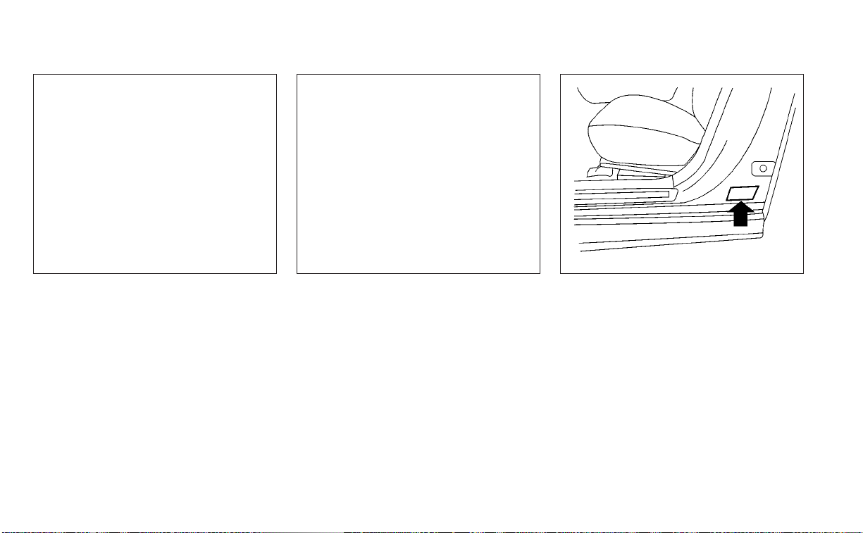
ENGINE SERIAL NUMBER
The number is stamped on the engine as
shown.
F.M.V.S.S./C.M.V.S.S. CERTIFICATION
LABEL
The Federal/Canadian Motor Vehicle
Safety Standard (F.M.V.S.S./C.M.V.S.S.) certifi-
cation label is affixed as shown. This label
contains valuable vehicle information, such
as: (GVWR), (GAWR), month and year of
manufacture, (VIN), etc. Review it carefully.
LTI2381
2.5L 4 cylinder (PR25DD engine model)
LTI2328
2.0L 4 cylinder (KR20DDET engine
model)
WTI0172
Technical and consumer information 10-13
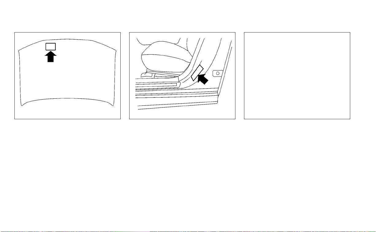
EMISSION CONTROL
INFORMATION LABEL
The emission control information label is
attached to the underside of the hood as
shown.
TIRE AND LOADING INFORMATION
LABEL
The cold tire pressure is shown on the Tire
and Loading Information label. The label is
located as shown.
AIR CONDITIONER SPECIFICATION
LABEL
The air conditioner specification label is af-
fixed to the underside of the hood as
shown.
WTI0173 WTI0174 LTI2271
10-14 Technical and consumer information

Symbol Name Reference Graphic
Caution ISO 7000 0434
Air Conditioning System
(MAC)
ISO 2575 D01
MAC System Lubricant Type
(PAG–POE)
Requires Registered Technician to
Service MAC System
Flammable Refrigerant
Air Conditioner Specification Label Symbols
To mount the front license plate, attach the
license plate bracket to the bumper fascia
at the location marks (small dimples) using
the two provided screws
O
A
.
LTI2380
INSTALLING FRONT LICENSE PLATE
Technical and consumer information 10-15

WARNING
• It is extremely dangerous to
ride in a cargo area inside a ve-
hicle. In a collision, people rid-
ing in these areas are more
likely to be seriously injured or
killed.
• Do not allow people to ride in
any area of your vehicle that is
not equipped with seats and
seat belts.
• Be sure everyone in your ve-
hicle is in a seat and using a
seat belt properly.
TERMS
It is important to familiarize yourself
with the following terms before
loading your vehicle:
• Curb Weight (actual weight of your
vehicle) - vehicle weight including:
standard and optional equipment,
fluids, emergency tools, and spare
tire assembly. This weight does
not include passengers and cargo.
• GVW (Gross Vehicle Weight) - curb
weight plus the combined weight
of passengers and cargo.
• GVWR (Gross Vehicle Weight Rat-
ing) - maximum total combined
weight of the unloaded vehicle,
passengers, cargo, hitch, trailer
tongue load and any other op-
tional equipment. This information
is located on the F.M.V.S.S./
C.M.V.S.S. certification label.
• GAWR (Gross Axle Weight Rating) -
maximum weight (load) limit
specified for the front or rear axle.
This information is located on the
F.M.V.S.S./C.M.V.S.S. certification
label.
• GCWR (Gross Combined Weight
Rating) - The maximum total
weight rating of the vehicle, pas-
sengers, cargo, and trailer.
• Vehicle Capacity Weight, Load limit,
Total load capacity - maximum to-
tal weight limit specified of the load
(passengers and cargo) for the ve-
hicle. This is the maximum com-
bined weight of occupants and
cargo that can be loaded into the
vehicle. If the vehicle is used to tow
a trailer, the trailer tongue weight
must be included as part of the
cargo load. This information is lo-
cated on the Tire and Loading In-
formation label.
VEHICLE LOADING INFORMATION
10-16 Technical and consumer information

• Cargo capacity - permissible
weight of cargo, the subtracted
weight of occupants from the load
limit.
VEHICLE LOAD CAPACITY
Before driving a loaded vehicle, con-
firm that you do not exceed the
Gross Vehicle Weight Rating (GVWR)
or the Gross Axle Weight Rating
(GAWR) for your vehicle. Both the
GVWR and GAWR are located on the
F.M.V.S.S./C.M.V.S.S. certification label.
For additional information, see “Mea-
surement of weights” (P. 10-20).
Do not exceed the load limit of your
vehicle shown as “The combined
weight of occupants and cargo” on
the Tire and Loading Information la-
bel. Do not exceed the number of
occupants shown as “Seating Ca-
pacity” on the Tire and Loading Infor-
mation label.
To get “the combined weight of oc-
cupants and cargo”, add the weight
of all occupants, then add the total
cargo weight. Examples are shown
in the following illustration.
Technical and consumer information 10-17

Steps For Determining Correct
Load Limit
1. Locate the statement “The com-
bined weight of occupants and
cargo should never exceed XXX kg
or XXX lbs.” on your vehicle’s
placard.
2. Determine the combined weight
of the driver and passengers that
will be riding in your vehicle.
3. Subtract the combined weight of
the driver and passengers from
XXX kg or XXX lbs.
4. The resulting figure equals the
available amount of cargo and
luggage load capacity. For ex-
ample, if the “XXX” amount equals
1400 lbs. and there will be five 150
lbs. passengers in your vehicle,
the amount of available cargo
and luggage load capacity is 650
lbs. (1400-750 (5 X 150) = 650 lbs.)
LTI2335
Example
10-18 Technical and consumer information

5. Determine the combined weight
of luggage and cargo being
loaded on the vehicle. That weight
may not safely exceed the avail-
able cargo and luggage load ca-
pacity calculated in step 4.
6. If your vehicle will be towing a
trailer, load from your trailer will be
transferred to your vehicle. Con-
sult this manual to determine
how this reduces the available
cargo and luggage load capacity
of your vehicle.
Towing a trailer with a vehicle that is
not intended for towing may result in
an accident involving injury or death.
WARNING
Do not tow a trailer with your vehicle.
Towing a trailer may result in an acci-
dent involving injury or death.
Before driving a loaded vehicle, con-
firm that you do not exceed the
Gross Vehicle Weight Rating (GVWR)
or the Gross Axle Weight Rating
(GAWR) for your vehicle. For addi-
tional information, see “Measure-
ment of weights” (P. 10-20).
Also check tires for proper inflation
pressures. For additional informa-
tion, see “Tire and Loading Informa-
tion label” (P. 8-31).
LOADING TIPS
• The GVW must not exceed GVWR or
GAWR as specified on the F.M.V.S.S./
C.M.V.S.S. certification label.
• Do not load the front and rear axle
to the GAWR. Doing so will exceed
the GVWR.
WARNING
• Properly secure all cargo with
ropes or straps to help prevent
it from sliding or shifting. Do
not place cargo higher than the
seatbacks. In a sudden stop or
collision, unsecured cargo
could cause personal injury.
• Do not load your vehicle any
heavier than the GVWR or the
maximum front and rear
GAWRs. If you do, parts of your
vehicle can break, tire damage
could occur, or it can change
the way your vehicle handles.
This could result in loss of con-
trol and cause personal injury.
Technical and consumer information 10-19

• Overloading not only can
shor ten the life of your vehicle
and the tire, but can also cause
unsafe vehicle handling and
longer braking distances. This
may cause a premature tire
failure which could result in a
serious accident and personal
injury. Failures caused by over-
loading are not covered by the
vehicle’s warranty.
MEASUREMENT OF WEIGHTS
Secure loose items to prevent
weight shifts that could affect the
balance of your vehicle. When the ve-
hicle is loaded, drive to a scale and
weigh the front and the rear wheels
separately to determine axle loads.
Individual axle loads should not ex-
ceed either of the Gross Axle Weight
Ratings (GAWR). The total of the axle
loads should not exceed the Gross
Vehicle Weight Rating (GVWR). These
ratings are given on the vehicle cer-
tification label. If weight ratings are
exceeded, move or remove items to
bring all weights below the ratings.
Do not tow a trailer with your vehicle.
FLAT TOWING
Towing your vehicle with all four wheels on
the ground is sometimes called flat towing.
This method is sometimes used when
towing a vehicle behind a recreational ve-
hicle, such as a motor home.
CAUTION
• Failure to follow these guidelines can
result in severe transmission
damage.
• Whenever flat towing your vehicle,
always tow forward, never backward.
• Never tow your front wheel drive ve-
hicle with the front tires on the
ground. Doing so may cause serious
and expensive damage to the
powertrain.
• DO NOT tow any continuously vari-
able transmission vehicle with all
four wheels on the ground (flat tow-
ing). Doing so WILL DAMAGE internal
transmission parts due to lack of
transmission lubrication.
• For emergency towing procedures
see “Towing recommended by
NISSAN” (P. 6-14).
TOWING A TRAILER
10-20 Technical and consumer information

Continuously Variable
Transmission (CVT)
To tow a vehicle equipped with a CVT, an
appropriate vehicle dolly MUST be placed
under the towed vehicle's drive wheels. Al-
ways follow the dolly manufacturer's rec-
ommendations when using their product.
DOT (Department of Transportation) Qual-
ity Grades: All passenger car tires must
conform to federal safety requirements in
addition to these grades.
Quality grades can be found where appli-
cable on the tire sidewall between tread
shoulder and maximum section width. For
example:
Treadwear 200 Traction AA Temperature
A
Treadwear
The treadwear grade is a comparative rat-
ing based on the wear rate of the tire when
tested under controlled conditions on a
specified government test course. For ex-
ample, a tire graded 150 would wear one
and one-half (1 1/2) times as well on the
government course as a tire graded 100.
The relative performance of tires depends
upon the actual conditions of their use,
however, and may depart significantly from
the norm due to variations in driving habits,
service practices and differences in road
characteristics and climate.
Traction AA, A, B and C
The traction grades, from highest to low-
est, are AA, A, B, and C. Those grades repre-
sent the tire's ability to stop on wet pave-
ment as measured under controlled
conditions on specified government test
surfaces of asphalt and concrete. A tire
marked C may have poor traction
performance.
WARNING
The traction grade assigned to this tire
is based on straight-ahead braking
traction tests, and does not include ac-
celeration, cornering, hydroplaning, or
peak traction characteristics.
Temperature A, B and C
The temperature grades are A (the high-
est), B, and C, representing the tire’s resis-
tance to the generation of heat, and its
ability to dissipate heat when tested under
controlled conditions on a specified indoor
laboratory test wheel. Sustained high tem-
perature can cause the material of the tire
to degenerate and reduce tire life, and ex-
cessive temperature can lead to sudden
tire failure. The grade C corresponds to a
level of performance which all passenger
car tires must meet under the Federal Mo-
tor Safety Standard No. 109. Grades B and A
represent higher levels of performance on
the laboratory test wheel than the mini-
mum required by law.
UNIFORM TIRE QUALITY GRADING
Technical and consumer information 10-21

WARNING
The temperature grade for this tire is
established for a tire that is properly
inflated and not overloaded. Excessive
speed, under-inflation, or excessive
loading, either separately or in combi-
nation, can cause heat build-up and
possible tire failure.
Your NISSAN vehicle is covered by the fol-
lowing emission warranties:
For USA
1. Emission Defects Warranty
2. Emissions Performance Warranty
Details of this warranty may be found with
other vehicle warranties in your Warranty
Information Booklet which comes with
your NISSAN vehicle. If you did not receive a
Warranty Information Booklet, or it is lost,
you may obtain a replacement by writing
to:
• Nissan North America, Inc.
Consumer Affairs Department
P.O. Box 685003
Franklin, TN 37068-5003
For Canada
Emission Control System Warranty
Details of this warranty may be found with
other vehicle warranties in your Warranty
Information Booklet which comes with
your NISSAN vehicle. If you did not receive a
Warranty Information Booklet, or it is lost,
you may obtain a replacement by writing
to:
• Nissan Canada Inc.
5290 Orbitor Drive
Mississauga, Ontario, L4W 4Z5
For USA
If you believe that your vehicle has a
defect which could cause a crash or
could cause injury or death, you
should immediately inform the Na-
tional Highway Traffic Safety Admin-
istration (NHTSA) in addition to noti-
fying NISSAN.
If NHTSA receives similar complaints,
it may open an investigation, and if it
finds that a safety defect exists in a
group of vehicles, it may order a re-
call and remedy campaign. However,
NHTSA cannot become involved in
individual problems between you,
your dealer, or NISSAN.
To contact NHTSA, you may call the
Vehicle Safety Hotline toll-free at
1-888-327-4236 (TTY: 1-800-424-
9153); go to http://www.safercar.gov;
or write to: Administrator, NHTSA,
400 Seventh Street, SW., Washington,
D.C. 20590. You can also obtain other
information about motor vehicle
EMISSION CONTROL SYSTEM
WARRANTY
REPORTING SAFETY DEFECTS
10-22 Technical and consumer information

safety from
http://www.safercar.gov.
You may notify NISSAN by contact-
ing our Consumer Affairs Depart-
ment, toll-free, at 1-800-NISSAN-1.
For Canada
If you believe that your vehicle has a
defect which could cause a crash or
could cause injury or death, you
should immediately inform Trans-
port Canada in addition to notifying
NISSAN.
If Transport Canada receives com-
plaints, it may open an investigation,
and if it finds that a safety defect
exists in a group of vehicles, it may
request that NISSAN conduct a recall
campaign. However, Transport
Canada cannot become involved in
individual problems between you,
your dealer, or NISSAN.
You may contact Transport Cana-
da's Defect Investigations and Re-
calls Division toll free at 1-800-333-
0510. You may also report safety
defects online at: http://
www.tc.gc.ca/eng/
motorvehiclesafety/menu.htm
(English speakers) or http://
www.tc.gc.ca/fra/
securiteautomobile/menu.htm
(French speakers)
Or contact Transport Canada by
mail at:
Transport Canada Motor Vehicle
Safety Investigations Laboratory
80 Noel Street Gatineau, QC J8Z0A1
Additional information concerning
motor vehicle safety may be ob-
tained from Transport Canada's
Road Safety Information Centre at
1-800-333-0371 or online at
www.tc.gc.ca/roadsafety (English
speakers) or www.tc.gc.ca/
securiteroutiere (French speakers).
To notify NISSAN of any safety con-
cerns please contact our Consumer
Information Centre toll free at
1-800-387-0122.
Technical and consumer information 10-23

WARNING
A vehicle equipped with All -Wheel
Drive (AWD) should never be tested us-
ing a two wheel dynamometer (such as
the dynamometers used by some
states for emissions testing), or similar
equipment. Make sure you inform the
test facility personnel that your vehicle
is equipped with AWD before it is placed
on a dynamometer. Using the wrong
test equipment may result in drivetrain
damage or unexpected vehicle move-
ment which could result in serious ve-
hicle damage or personal injury.
Due to legal requirements in some states
and Canadian Provinces, your vehicle may
be required to be in what is called the
“ready condition” for an Inspection/
Maintenance (I/M) test of the emission
control system.
The vehicle is set to the “ready condition”
when it is driven through certain driving
patterns. Usually, the ready condition can
be obtained by ordinary usage of the
vehicle.
If a powertrain system component is re-
paired or the battery is disconnected, the
vehicle may be reset to a “not ready” condi-
tion. Before taking the I/M test, check the
vehicle's inspection/maintenance test
readiness condition. Place the ignition
switch in the ON position without starting
the engine. If the Malfunction Indicator
Light (MIL) comes on steady for 20 seconds
and then blinks for 10 seconds , the I/M test
condition is “not ready”. If the MIL does not
blink after 20 seconds, the I/M test condi-
tion is “ready”. It is recommended that you
visit a NISSAN dealer to set the “ready con-
dition” or to prepare the vehicle for testing.
This vehicle is equipped with an Event Data
Recorder (EDR). The main purpose of an
EDR is to record, in certain crash or near
crash-like situations, such as an air bag
deployment or hitting a road obstacle, data
that will assist in understanding how a ve-
hicle's systems performed. The EDR is de-
signed to record data related to vehicle dy-
namics and safety systems for a short
period of time, typically 30 seconds or less.
The EDR in this vehicle is designed to re-
cord such data as:
• How various systems in your vehicle were
operating;
• Whether or not the driver and passenger
safety belts were buckled/fastened;
• How far (if at all) the driver was depress-
ing the accelerator and/or brake pedal;
and,
• How fast the vehicle was traveling.
• Sounds are not recorded.
These data can help provide a better un-
derstanding of the circumstances in which
crashes and injuries occur. NOTE: EDR data
are recorded by your vehicle only if a non-
trivial crash situation occurs; no data are
recorded by the EDR under normal driving
conditions and no personal data (e.g.,
name, gender, age, and crash location) are
recorded. However, other parties, such as
READINESS FOR INSPECTION/
MAINTENANCE (I/M) TEST
EVENT DATA RECORDERS (EDR)
10-24 Technical and consumer information

law enforcement, could combine the EDR
data with the type of personally identifying
data routinely acquired during a crash
investigation.
To read data recorded by an EDR, special
equipment is required, and access to the
vehicle or the EDR is needed. In addition to
the vehicle manufacturer and NISSAN
dealer, other parties, such as law enforce-
ment, that have the special equipment, can
read the information if they have access to
the vehicle or the EDR. EDR data will only be
accessed with the consent of the vehicle
owner or lessee or as otherwise required or
permitted by law.
ADDITIONAL DATA RECORDING (on
vehicles equipped with optional
ProPILOT Assist)
If your vehicle is equipped with the optional
ProPILOT Assist, it will also be equipped
with a supplemental vehicle data record-
ing function.
The data recording function is designed to
record such data as:
• Driver operational status of accelerator,
brakes, steering, etc.
• Detection status of a vehicle ahead and
lane markers
• Vehicle information including distance to
vehicle ahead and lateral position
• Information on the operation of the Pro-
PILOT Assist and other crash avoidance
features
• ProPILOT Assist malfunction diagnosis
information
• External images from multi-sensing front
camera (Available only when SRS air bag
or AEB with Pedestrian Detection system
is activated)
ProPILOT Assist does not record conversa-
tions, sounds or images of the inside of the
vehicle.
To read this vehicle data, special equip-
ment is required and access to the vehicle
or the recording unit is needed. This vehicle
data will only be accessed with the consent
of the vehicle owner or lessee or as other-
wise required or permitted by law.
If downloaded, NISSAN may use the data
recorded for the purpose of improving
NISSAN's vehicle safety performance.
NISSAN will not disclose/provide the re-
corded data to a third party except:
• With the consent of the vehicle owner or
with the consent of the lessee
• In response to an official request from law
enforcement, a court order, governmen-
tal agency, or other legally enforceable
requests
• For use as part of NISSAN's defense of
litigation
• For research purposes after the data is
modified such that it is no longer tied to a
specific vehicle or vehicle owner
If you have any questions regarding the
data NISSAN may collect about you, please
visit our Privacy Policy:
https://www.nissanusa.com.
Technical and consumer information 10-25

Genuine NISSAN Service Manuals for this
model year and prior can be purchased. A
Genuine NISSAN Service Manual is the best
source of service and repair information for
your vehicle. This manual is the same one
used by the factory-trained technicians
working at NISSAN dealerships. Genuine
NISSAN Owner’s Manuals can also be
purchased.
For USA
For current pricing and availability of Genu-
ine NISSAN Service Manuals, contact:
www.nissan-techinfo.com
For current pricing and availability of Genu-
ine NISSAN Owner's Manuals, contact:
1-800-247-5321
For Canada
To purchase a copy of a Genuine NISSAN
Service Manual or Owner’s Manual, for this
model year and prior, please contact your
nearest NISSAN dealer. For the phone num-
ber and location of a NISSAN dealer in your
area, call the NISSAN Information Center at
1-800-387-0122 and a bilingual NISSAN rep-
resentative will assist you.
OWNER'S MANUAL/SERVICE
MANUAL ORDER INFORMATION
10-26 Technical and consumer information

11 Index
A
Active noise cancellation
Active sound enhancement
......5-162
Active Ride Control (ARC)
.........5-153
Air bag (See supplemental restraint
system)
.....................1-46
Air bag system
Front (See supplemental front impact air
bag system)
................1-54
Air bag warning light
.........1-67, 2-12
Air bag warning light,
supplemental
..............1-67, 2-12
Air cleaner housing filter
..........8-18
Air conditioner
Air conditioner operation
. . . .4-34, 4-40
Air conditioner specification label
. .10-14
Air conditioner system refrigerant
recommendations
............10-8
Air conditioner system refrigerant and oil
recommendations
............10-8
Heater and air conditioner
controls
...............4-32, 4-40
Servicing air conditioner
........4-43
Air flow charts
................4-35
Alarm system (See vehicle security
system)
....................2-50
All-Wheel Drive
................5-143
Anchor point locations
...........1-28
Antenna
....................4-63
Anti-lock Braking System (ABS)
.....5-148
Antifreeze
...................5-160
Armrests
.....................1-7
Audio system
.................4-44
AM radio operation
............4-50
AM radio reception
............4-44
AM/FM radio
............4-48, 4-50
Auxiliary (AUX) devices operation
. . .4-52
Bluetooth® audio
.............4-59
FM radio operation
............4-51
FM radio reception
............4-44
iPod® Player
................4-56
iPod® player operation
.........4-56
Radio
....................4-44
USB (Universal Serial Bus) Connection
Port
.....................4-53
USB Connections
.............4-54
USB interface
...............4-53
Autolight switch
...............2-56
Automatic
Automatic power window switch
. . .2-73
Automatic anti-glare inside mirror
. . . .3-29
Automatic brake hold
............5-27
Automatic door locks
.............3-6
Automatic Emergency Braking
(AEB)
...................2-13,2-16
Automatic Emergency Braking (AEB) with
Pedestrian Detection
............5-111
AWD
......................5-143
B
Battery
.................5-160, 8-14
Charge warning light
...........2-11
Battery replacement
............8-23
Key fob
...................8-23
NISSAN Intelligent Key®
.........8-24
Before starting the engine
.........5-16
Belt (See drive belt)
..............8-16
Blind Spot Warning (BSW)
.........5-46
Bluetooth® audio
..............4-59
Bluetooth® hands-free phone
system
.....................4-66
Bluetooth® connections
........4-80
Connecting procedure
..........4-71
Phone indicators
.............4-70
Text messaging
..............4-76
Voice commands
.............4-72
Booster seats
.................1-42
Brake
Anti-lock Braking System (ABS)
. . . .5-148
Brake fluid
.................8-12
Brake light (See stop light)
.......8-26
Brake system
..............5-148
Brake warning light
............2-10
Brake wear indicators
.......2-18,8-20
Self-adjusting brakes
..........8-20
Brake Assist
.................5-150
Brake fluid
...................8-12
Brake system
................5-148
Brakes
.....................8-20

Break-in schedule
..............5-142
Brightness control
Instrument panel
.............2-60
Brightness/contrast button
.........4-7
Bulb check/instrument panel
........2-10
Bulb replacement
...............8-26
C
C.M.V.S.S. certification label
.........10-13
Capacities and recommended
fuel/lubricants
.................10-2
Car phone or CB radio
............4-66
Cargo
(See vehicle loading information)
.....10-16
Chassis control
................5-153
Check tire pressure
..........2-30, 2-46
Child restraints
.......1-21,1-22,1-23,1-25
LATCH (Lower Anchors and Tethers for
CHildren) System
..............1-25
Precautions on child
restraints
............1-31, 1-38, 1-42
Top tether strap anchor point
locations
...................1-28
Child safety rear door lock
..........3-7
Cleaning exterior and interior
......7-2,7-5
Clock set/adjustment
.............4-5
Cold weather driving
............5-160
Console box
..................2-70
Continuously Variable Transmission
(CVT)
.......................5-18
Continuously Variable Transmission (CVT)
fluid
......................8-12
Driving with Continuously Variable
Transmission (CVT)
............5-18
Control panel buttons
.............4-3
Brightness/contrast button
........4-7
Controls
Audio controls (steering wheel)
.....4-62
Heater and air conditioner
controls
................4-32, 4-40
Coolant
Capacities and recommended
fuel/lubricants
...............10-2
Changing engine coolant
.........8-6
Checking engine coolant level
......8-6
Engine coolant temperature gauge
. . .2-6
Corrosion protection
..............7-8
Cruise control
.................5-68
Cup holders
...................2-71
D
Day time Running Light System
......2-60
Defroster switch
Rear window and outside mirror defroster
switch
....................2-54
Dimensions and weights
..........10-11
Dimmer switch for instrument panel
. . .2-60
Display controls (see control panel
buttons)
.....................4-3
Door locks
....................3-4
Drive belt
....................8-16
Driving
Cold weather driving
...........5-160
Driving with Continuously Variable
Transmission (CVT)
............5-18
Precautions when starting and
driving
..................5-4, 5-10
Driving the vehicle
...............5-18
E
Economy - fuel
................5-143
Emergency call (SOS) button
........2-65
Emergency engine shutoff
.......5-15,6-2
Emission control information label
. . . .10-14
Emission control system warranty
. . . .10-22
Engine
Before starting the engine
........5-16
Capacities and recommended
fuel/lubricants
...............10-2
Changing engine coolant
.........8-6
Changing engine oil
............8-8
Changing engine oil filter
.........8-8
Checking engine coolant level
......8-6
Checking engine oil level
..........8-7
Engine compartment check
locations
...................8-3
Engine coolant temperature gauge
. . .2-6
Engine cooling system
...........8-5
Engine oil
...................8-7
Engine oil and oil filter
recommendation
.............10-7
Engine oil pressure warning light
. . . .2-11
Engine oil viscosity
.............10-7
Engine serial number
..........10-13
Engine specifications
...........10-9
11-2

Starting the engine
............5-16
Engine Block Heater
.............5-161
Engine coolant temperature gauge
. . . .2-6
Event Data recorders
........10-24, 10-25
Exhaust gas (Carbon monoxide)
......5-4
Explanation of maintenance items
.....9-2
Explanation of scheduled maintenance
items
.......................9-5
Ex tended storage switch
..........2-68
Eyeglass case
.................2-70
F
F.M.V.S.S. certification label
.........10-13
Flashers (See hazard warning flasher
switch)
......................6-2
Flat tire
...................6-3, 6-4
Floor mat positioning aid
...........7-7
Fluid
Brake fluid
..................8-12
Capacities and recommended
fuel/lubricants
...............10-2
Continuously Variable Transmission (CVT)
fluid
......................8-12
Engine coolant
................8-5
Engine oil
...................8-7
Windshield-washer fluid
.........8-13
Fog light switch
................2-61
Front air bag system
(See supplemental restraint system)
. . .1-54
Front power seat adjustment
........1-4
Front seats
....................1-2
Front-door pocket
..............2-69
Fuel
Capacities and recommended
fuel/lubricants
...............10-2
Fuel economy
...............5-143
Fuel gauge
..................2-7
Fuel octane rating
.............10-6
Fuel recommendation
..........10-4
Fuel-filler door and cap
..........3-25
Fuel-filler door lock opener lever
. . . .3-25
Loose fuel cap warning
......2-28,2-44
Fuel efficient driving tips
..........5-142
Fuel gauge
....................2-7
Fuel-filler door
.................3-25
Fuses
.......................8-21
Fusible links
..................8-22
G
Garage door opener, HomeLink® Universal
Transceiver
.....2-78,2-79,2-80, 2-81, 2-82
Gas cap
.....................3-25
Gauge
Engine coolant temperature gauge
. . .2-6
Fuel gauge
..................2-7
Speedometer
................2-4
Tachometer
.................2-6
Trip odometer
................2-5
General maintenance
.............9-2
Glove box
....................2-70
Glove box lock
.................2-70
H
Hands-free phone system, Bluetooth®
. .4-66
Hazard warning flasher switch
........6-2
Head restraints
.................1-7
Headlight and turn signal switch
.....2-55
Headlight control switch
...........2-55
Headlights
...................8-25
Heated seat switches
............2-62
Heated steering wheel
............2-63
Heater
Heater and air conditioner
controls
................4-32, 4-40
Heater operation
..........4-33, 4-41
Hill start assist system
...........5-153
HomeLink® Universal
Transceiver
.....2-78,2-79,2-80, 2-81, 2-82
Hood
.......................3-22
Horn
.......................2-62
I
Ignition switch
Push-button ignition switch
.......5-13
Immobilizer system
..........2-52, 5-16
Important vehicle information label
. . .10-13
In-cabin microfilter
..............8-18
Increasing fuel economy
..........5-143
Indicator
NISSAN Intelligent Key® battery discharge
indicator
...................5-15
Inside automatic anti-glare mirror
. . . .3-29
Instrument brightness control
.......2-60
11-3

Instrument panel
.............0-6, 2-2
Instrument panel dimmer switch
.....2-60
Intelligent Around View Monitor
......4-15
Intelligent Cruise Control (ICC)
(for vehicles with ProPILOT Assist)
.....5-82
Intelligent Driver Alertness (I-DA)
.....5-138
Intelligent Forward Collision Warning
(I-FCW )
.....................5-123
Intelligent Key system
Key operating range
............3-9
Key operation
................3-10
Mechanical key
................3-3
Remote keyless entry operation
. . . .3-14
Troubleshooting guide
..........3-17
Warning signals
...............3-17
Intelligent Lane Intervention (I-LI)
.....5-40
Intelligent Trace Control (I-TC)
.......5-153
Interior light
...................2-76
Interior trunk lid release
...........3-24
iPod® Player
..................4-56
ISOFIX child restraints
.............1-25
J
Jump starting
..............6-11,8-15
K
Key
.........................3-2
Key fob battery replacement
........8-23
Keyless entry
With Intelligent Key system
(See Intelligent Key system)
.......3-14
Keys
NISSAN Intelligent Key®
...........3-2
NISSAN Vehicle Immobilizer System
keys
......................3-4
L
Label
Tire and Loading Information label
. .10-14
Labels
Air conditioner specification label
. . .10-14
C.M.V.S.S. certification label
.......10-13
Emission control information label
. .10-14
Engine serial number
..........10-13
F.M.V.S.S. certification label
........10-13
Tire and Loading Information label
. .10-14
Vehicle identification number (VIN)
plate
.....................10-12
Warning labels (for SRS)
..........1-67
Lane Departure Warning (LDW)
.......5-33
LATCH (Lower Anchors and Tethers for
CHildren) System
...............1-25
Launch bar menu
................4-7
License plate
Installing the license plate
........10-15
Light
Air bag warning light
........1-67, 2-12
Brake light (See stop light)
........8-26
Bulb check/instrument panel
......2-10
Bulb replacement
.............8-26
Charge warning light
............2-11
Ex terior and Interior lights
........8-26
Fog light switch
...............2-61
Fog lights
..................8-26
Headlight and turn signal switch
. . . .2-55
Headlight control switch
.........2-55
Headlights
..................8-25
Interior light
.................2-76
Light bulbs
.................8-25
Low tire pressure warning light
.....2-13
Low windshield-washer fluid warning
light
..................2-29,2-45
Personal lights
...............2-77
Security indicator light
..........2-12
Spotlights (See map light)
........2-77
Trunk light
..................2-78
Lights
......................8-25
Map lights
..................2-77
Lock
Child safety rear door lock
.........3-7
Door locks
..................3-4
Fuel-filler door lock opener lever
. . . .3-25
Glove box lock
...............2-70
Power door locks
..............3-6
Trunk lid lock opener lever
........3-22
Loose fuel cap warning
........2-28,2-44
Low fuel warning light
. .2-12, 2-16, 2-28, 2-45
Low tire pressure warning light
.......2-13
Low windshield-washer fluid warning
light
....................2-29,2-45
Luggage (See vehicle loading
information)
..................10-16
11-4

M
Maintenance
General maintenance
...........9-2
Inside the vehicle
..............9-3
Maintenance precautions
.........8-2
Outside the vehicle
.............9-3
Seat belt maintenance
..........1-20
Under the hood and vehicle
.......9-4
Maintenance requirements
..........9-2
Maintenance schedules
............9-7
Malfunction indicator light
..........2-15
Manual front seat adjustment
........1-3
Map lights
....................2-77
Memory seat
...........3-31, 3-32, 3-33
Menu button
...................4-5
Meters and gauges
..............2-4
Instrument brightness control
.....2-60
Mirror
Automatic anti-glare inside mirror
. . .3-29
Outside mirrors
..............3-30
Rearview
...................3-29
Vanity mirror
................3-29
Mirrors
......................3-29
Moonroof
.................2-75,7-5
Moving Object Detection (MOD)
......4-26
N
NISSAN Intelligent Key®
............3-2
NISSAN Intelligent Key® battery discharge
indicator
.....................5-15
NISSAN Vehicle Immobilizer
System
..................2-52, 5-16
NissanConnect® Owner's Manual
......4-2
O
Octane rating (See fuel octane rating)
. .10-6
Oil
Capacities and recommended
fuel/lubricants
...............10-2
Changing engine oil
............8-8
Changing engine oil filter
.........8-8
Checking engine oil level
..........8-7
Engine oil
...................8-7
Engine oil and oil filter
recommendation
.............10-7
Engine oil viscosity
.............10-7
Outside mirrors
................3-30
Overhead sunglasses holder
........2-70
Overheat
If your vehicle overheats
.........6-13
Owner's manual order form
........10-26
Owner's manual/service manual order
information
..................10-26
P
Parking
Parking/parking on hills
.........5-146
Parking brake
........2-11,2-13,2-17,5-24
Personal lights
.................2-77
Phone, Bluetooth® hands-free system
. .4-66
Power
Power door locks
..............3-6
Power outlet
................2-67
Powerrearwindows
............2-73
Power steering system
.........5-147
Power windows
..............2-72
Rear power windows
...........2-73
Power outlet
..................2-67
Power steering
................5-147
Precautions
Maintenance precautions
.........8-2
Precautions on booster
seats
...............1-31, 1-38, 1-42
Precautions on child
restraints
............1-31, 1-38, 1-42
Precautions on seat belt usage
.....1-12
Precautions on supplemental restraint
system
....................1-46
Precautions when starting and
driving
..................5-4, 5-10
ProPILOT Assist
................5-70
Push starting
..................6-13
R
Radio
Car phone or CB radio
..........4-66
FM/AM radio
................4-48
Readiness for inspection maintenance
(I/M) test
....................10-24
Rear Automatic Braking (RAB)
.......5-104
Rear Cross Traffic Alert (RCTA)
.......5-58
Rear Door Aler t
. .2-27, 2-28, 2-43, 2-44, 2-65
11-5

Rear power windows
.............2-73
Rear seat
.....................1-5
Rear Sonar System (RSS)
..........5-154
Rear window and outside mirror defroster
switch
......................2-54
Rearview mirror
................3-29
RearView Monitor
................4-8
Recommended Fluids
............10-2
Recorders
Event Data
.............10-24, 10-25
Refrigerant recommendation
.......10-8
Registering a vehicle in another
country
.....................10-12
Remote Engine Start
..........3-19,5-17
Reporting safety defects (US only)
. . . .10-22
S
Safety
Child safety rear door lock
.........3-7
Child seat belts
.....1-23,1-31, 1-38, 1-42
Reporting safety defects (US only)
. .10-22
Seat
Memory seat
.........3-31, 3-32, 3-33
Seat adjustment
Front manual seat adjustment
......1-3
Front power seat adjustment
.......1-4
Rear seat adjustment
............1-5
Seat belt
Child safety
..................1-21
Infants and small children
.....1-21,1-22
Injured person
................1-15
Larger children
...............1-22
Precautions on seat belt usage
.....1-12
Pregnant women
..............1-15
Seat belt extenders
............1-20
Seat belt maintenance
..........1-20
Seat belts
................1-12,7-7
Shoulder belt height adjustment
. . . .1-19
Three-point type with retractor
.....1-15
Seat belt extenders
..............1-20
Seat belt warning light
.........1-14,2-12
Seatback pockets
...............2-69
Seats
Adjustment
..................1-2
Armrests
....................1-7
Front seats
..................1-2
Manual front seat adjustment
......1-3
Rear seat
...................1-5
Security indicator light
............2-12
Security system (NISSAN Vehicle Immobilizer
System), engine start
.........2-52, 5-16
Security systems
Vehicle security system
.........2-50
Self-adjusting brakes
.............8-20
Service manual order form
........10-26
Servicing air conditioner
...........4-43
Shift lever lock release
............5-22
Shifting
Continuously Variable Transmission
(CVT)
.....................5-20
Shoulder belt height adjustment
......1-19
Siri® Eyes-Free
.................4-63
Sonar
Rear system
................5-154
Spark plug replacement
...........8-17
Spark plugs
...................8-17
Specifications
.................10-9
Speedometer
..................2-4
Spotlights (See map light)
..........2-77
SRS warning label
...............1-67
Stability control
................5-150
Standard maintenance
........9-10,9-28
Starting
Before starting the engine
........5-16
Jump starting
.............6-11,8-15
Precautions when starting and
driving
..................5-4, 5-10
Push starting
................6-13
Starting the engine
............5-16
Starting the engine
..............5-16
Steering
Heated steering wheel
..........2-63
Power steering system
.........5-147
Steering Assist switch
(for vehicles with ProPILOT Assist)
.....2-64
Steering wheel
.................3-27
Stop light
....................8-26
Storage
.....................2-69
Sun visors
....................3-28
Sunglasses case
................2-70
Sunglasses holder
..............2-70
Sunroof
...................2-75,7-5
Supplemental air bag warning
light
....................1-67, 2-12
Supplemental front impact air bag
system
......................1-54
Supplemental restraint system
Information and warning labels
.....1-67
Precautions on supplemental restraint
system
....................1-46
11-6

Supplemental restraint system
(Supplemental air bag system)
.......1-46
Switch
Autolight switch
..............2-56
Automatic power window switch
. . . .2-73
Fog light switch
...............2-61
Hazard warning flasher switch
......6-2
Headlight and turn signal switch
. . . .2-55
Headlight control switch
.........2-55
Instrument brightness control
.....2-60
Power door lock switch
..........3-6
Rear window and outside mirror defroster
switch
....................2-54
Turn signal switch
.............2-61
T
Tachometer
...................2-6
Temperature gauge
Engine coolant temperature gauge
. . .2-6
Theft (NISSAN Vehicle Immobilizer System),
engine start
...............2-52, 5-16
Three-way catalyst
...............5-4
Tilt
Telescopic steering
............3-27
Tire
Flat tire
..................6-3, 6-4
Spare tire
................6-5, 8-41
Tire and Loading Information label
. .10-14
Tire chains
..................8-37
Tire pressure
................8-29
Tire rotation
.................8-38
Types of tires
................8-35
Uniform tire quality grading
.......10-21
Wheel/tire size
...............10-10
Wheels and tires
..............8-29
Tire pressure
Low tire pressure warning light
.....2-13
Tire Pressure Monitoring System
(TPMS)
....................5-5, 6-3
Towing
2-wheel drive models
...........6-16
All-wheel drive models
..........6-15
Flat towing
.................10-20
Trailer towing
...............10-20
Towing a trailer
................10-20
Towing your vehicle
..............6-14
Traffic Sign Recognition (TSR)
........5-30
Transceiver
HomeLink® Universal
Transceiver
. . .2-78, 2-79, 2-80, 2-81, 2-82
Transmission
Continuously Variable Transmission (CVT)
fluid
......................8-12
Driving with Continuously Variable
Transmission (CVT)
............5-18
Transmission shift lever lock release
. . .5-22
Travel (See registering a vehicle in another
country)
....................10-12
Trip odometer
..................2-5
Trunk access through the rear seat
.1-6, 3-24
Trunk lid
.....................3-22
Trunk lid lock opener lever
..........3-22
Trunk light
....................2-78
Turn signal switch
...............2-61
U
Uniform tire quality grading
........10-21
USB interface
.................4-53
USB/iPod® Charging Ports
.........4-63
V
Vanity mirror
..................3-29
Variable voltage control system
......8-16
Vehicle dimensions and weights
.....10-11
Vehicle Dynamic Control (VDC)
system
.....................5-150
Vehicle identification
.............10-12
Vehicle identification number (VIN)
(Chassis number)
...............10-12
Vehicle identification number (VIN)
plate
.......................10-12
Vehicle immobilizer system
.....2-52, 5-16
Vehicle information display
......2-18,2-33
Vehicle loading information
........10-16
Vehicle recover y
.............6-16,6-17
Vehicle security system
...........2-50
Vehicle security system (NISSAN Vehicle
Immobilizer System), engine start
.2-52, 5-16
Ventilators
...................4-30
Visors
......................3-28
Voice Prompt Interrupt
...........4-69
11-7

W
Warning
Air bag warning light
........1-67, 2-12
Battery charge warning light
.......2-11
Brake warning light
............2-10
Engine oil pressure warning light
. . . .2-11
Hazard warning flasher switch
......6-2
Loose fuel cap warning
......2-28,2-44
Low fuel warning
light
............2-12,2-16,2-28,2-45
Low tire pressure warning light
.....2-13
Low windshield-washer fluid warning
light
..................2-29,2-45
Seat belt warning light
.......1-14,2-12
Supplemental air bag warning
light
...................1-67, 2-12
Vehicle security system
.........2-50
Warning labels (for SRS)
..........1-67
Warning lights, indicator lights and audible
reminders
....................2-9
Weights (See dimensions and weights)
.10-11
Wheel/tire size
................10-10
Wheels and tires
................8-29
When traveling or registering in another
country
.....................10-12
Windows
.....................2-71
Locking passengers' windows
.....2-73
Powerrearwindows
............2-73
Power windows
..............2-72
Rear power windows
...........2-73
Windshield wiper blades
...........8-19
Windshield-washer fluid
...........8-13
Wiper
Wiper blades
................8-19
Wiper and washer switch
..........2-53
11-8

MEMO

MEMO

MEMO

MEMO

MEMO

MEMO

FUEL RECOMMENDATION:
Use unleaded regular gasoline with an oc-
tane rating of at least 87 AKI (Anti-Knock
Index) number (Research octane number
91).
CAUTION
• Only vehicles with the E-85 filler door
label can operate on E-85. Fuel sys-
tem or other damage can occur if
E-85 is used in vehicles that are not
designed to run on E-85.
• Using a fuel other than that specified
could adversely affect the emission
control system, and may also affect
the warranty coverage.
• Under no circumstances should a
leaded gasoline be used, because
this will damage the three-way
catalyst.
• Do not use a fuel containing more
than 15% ethanol in your vehicle. Your
vehicle is not designed to run on a
fuel containing more than 15% etha-
nol. Using a fuel containing more
than 15% ethanol in a vehicle not spe-
cifically designed for a fuel contain-
ing more than 15% ethanol can ad-
versely affect the emission control
devices and systems of the vehicle.
Damage caused by such fuel is not
covered by the NISSAN New Vehicle
Limited Warranty.
• Do not use fuel that contains the oc-
tane booster methylcyclopentadi-
enyl manganese tricarbonyl (MMT).
Using fuel containing MMT may ad-
versely affect vehicle performance
and vehicle emissions. Not all fuel
dispensers are labeled to indicate
MMT content, so you may have to
consult your gasoline retailer for
more details. Note that Federal and
California laws prohibit the use of
MMT in reformulated gasoline.
• U.S. government regulations require
ethanol dispensing pumps to be
identified by a small, square, orange
and black label with the common ab-
breviation or the appropriate per-
centage for that region.
For additional information, see “Recom-
mended fluids/lubricants and capacities”
(P. 10-2).
ENGINE OIL RECOMMENDATION:
For additional information, see “Recom-
mended fluids/lubricants and capacities”
(P. 10-2).
COLD TIRE PRESSURE:
For additional information, see “Tire and
Loading Information label” (P. 8-31).
The label is typically located on the driver
side center pillar or on the driver's door. For
additional information, see “Wheels and
tires” (P. 8-29).
GAS STATION INFORMATION

RECOMMENDED NEW VEHICLE
BREAK-IN PROCEDURE:
During the first 1,200 miles (2,000 km) of
vehicle use, follow the break-in procedure
recommendations for the future reliability
and economy of your new vehicle. For ad-
ditional information, see “Break-in sched-
ule” (P. 5-142). Failure to follow these recom-
mendations may result in vehicle damage
or shortened engine life.


L34-D
Printing : April 2021
Publication No.:
Printed in the U.S.A.
OM21EA 0L34U2