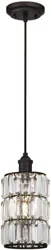
Mini-Pendant Kit
Installation and Safety Instructions
Warning: Be sure the electricity to the wires you are working on is shut off; either the fuse is removed
or the circuit breaker is shut off.
GENERAL
You don't need special tools to install this fixture. Be sure to follow the steps in the order given. Under no circumstances should
a fixture be hung on house electrical wires, nor should a swag type fixture be installed on a ceiling which contains a radiant type
heating system. Read instructions carefully. If you are unclear as to how to proceed, consult a qualified electrician.
INSTALLATION
Important: Do not attach fixture directly to outlet box.
Step 1: Thread mounting screw (A) into the matching hole of mounting bar (B).
Step 2: Secure the mounting bar (B) to outlet box with outlet box screws (C) (not provided).
ADJUSTING LENGTH OF CORD IF NEEDED
These steps should only be performed by someone familiar with working with electrical wiring. Care must be taken when adjust-
ing the length of the cord to ensure insulation on internal wires is not damaged. If not familiar with these steps, seek the aid of a
qualified electrician.
Step 1: Loosen the screw in strain relief (Q) until cord slides easily, being careful not to completely remove screw.
Slide canopy down cord until the fixture is the desired distance below the canopy. Tighten the screw in the strain
relief until cord does not slide.
Step 2: Cut excess cord approximately six to seven inches (6”-7”) above canopy.
Step 3: Leaving at least one inch (1”) of outer insulation above the canopy, carefully cut through outer insulation of cord,
being careful not to damage inner insulation. Remove outer insulation. Strip inner insulation from end of both
wires, leaving approximately 1/2 inch of wire exposed.
Step 4: For cords without differently colored inner insulation, identify the tracer lines on the new ends of the inner wires
to match the labels on the original ends and connect to house wiring as described in the appropriate step listed
below in the Grounding and Wiring Instructions section.
GROUNDING AND WIRING INSTRUCTIONS
Step 1: Insert the green grounding screw (G) into the hole with two raised dimples on the mounting bar (B). Wrap the bare
grounding wire (F) from the fixture canopy (D) around the green grounding screw's stem (G) on the mounting bar (B)
leaving enough excess wire.
Step 2: Connect the green grounding wire (H) from hanging cord and excess grounding wire (F) from the fixture canopy (D)
with the grounding wire (I) from outlet box by using a wire connector (P), then wrap the wire connector (P) with
electrical tape for a more secure connection. WARNING: Never connect grounding wire to black or white power
supply wires.
Step 3: Connect the black house wire with the black wire from the fixture by wire connector (P), and wrap the wire connector
(P) with electrical tape for a more secure connection.
Step 4: Con
nect the white house wire with the white wire from the fixture by wire connector
(P)
, and wrap th
e wire connector
(P) with electrical tape for a more secure connection.
Note: Try to gently pull the wire connectors (P) off of the wires. If you can pull the connector off, carefully repeat steps
2, 3 and 4 above, and check again for a firm connection. Make sure no bare wires can be seen protruding outside of
the wire connectors.
Step 5: Tighten green grounding screw (G). Do not over tighten.
FINAL ASSEMBLY
Step 1: After wires are connected, tuck them carefully inside outlet box. Raise canopy (D) allowing the
mounting screw (A) to protrude through the hole in the canopy (D), and secure with ball nut (E).
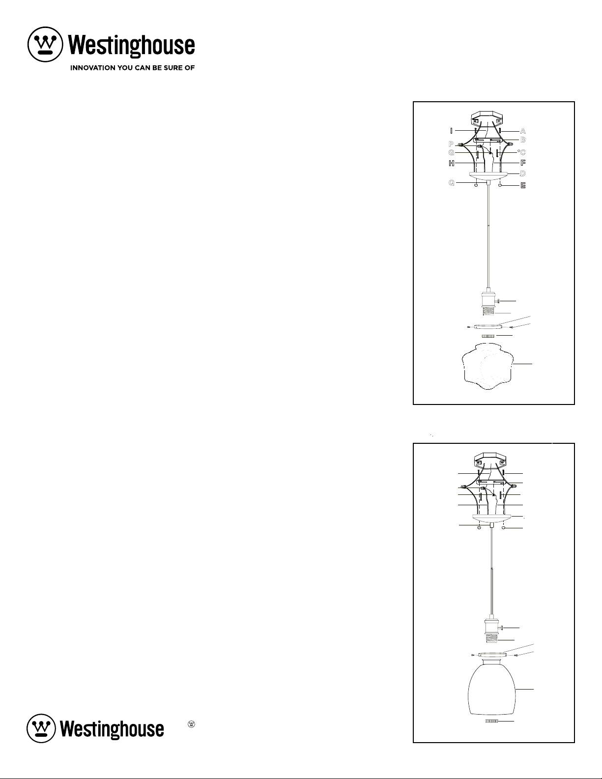
***For shade with a closed bottom, please follow below instruction (see figure 1):
Step 2a: Take off the retaining ring (L) from the socket (J). Install adaptor (M) to socket (J) with retaining ring (L) (if applicable).
Step 3a: Install lamp (not included). (Please do not exceed the maximum lamp wattage recommended on the socket).
Step 4a: Install the shade (Ka) to adaptor (M) and secure it by using thumb screws (N).
Step 5a: Turn on the switch (O) on the socket (if applicable).
***For shade with open bottom, please follow below instruction (see figure 2):
Step 2b: Take off the retaining ring (L) from the socket (J). Secure the adaptor (M) onto the shade (Kb) with thumb screw(s) (N)
(if applicable).
Step 3b: Install the shade (Kb) and adaptor (M) assembly onto the socket (J) and secure the retaining ring (L).
Step 4b: Install lamp (not included). (Please do not exceed the maximum lamp wattage recommended on the socket).
Step 5b: Turn on the switch (O) on the socket (if applicable).
CLEANING
To clean, wipe fixture with a soft cloth. Clean glass with a mild soap. Do not use abrasive materials such as scouring pads or
powders, steel wool or abrasive paper.
Westinghouse Lighting, Philadelphia, PA 19154-1029, U.S.A.
www.westinghouselighting.com
, WESTINGHOUSE, and INNOVATION YOU CAN BE SURE OF
are trademarks of Westinghouse Electric Corporation.
Used under license by Westinghouse Lighting.
All rights reserved.
Made in China
W-562
062818
*NOT SUPPLIED
*NOT SUPPLIED
P
B
H
Q
G
I
A
*C
F
D
E
M
N
L
Ka
J
O
B
H
Q
G
P
I
A
*C
F
D
E
J
O
L
Kb
M
N
FIGURE 1.
FIGURE 2.

Mini-Luminaire Suspendu
Installation et Instructions de Sécurité
Mise en garde: Veillez à ce que le courant soit coupé dans le circuit sur lequel vous travaillez, soit en ôtant le fusible soit en fermant le disjoncteur.
GÉNÉRALITÉS
Vous n'avez pas besoin d'outils spéciaux pour installer ce luminaire. Veillez à suivre les étapes dans l'ordre donné. Il ne faut jamais, en quelque circonstance que ce soit, suspendre un luminaire sur des fils électriques; de même, un
luminaire de type festonné ne doit pas être installé sur un plafond pourvu d'un système de chauffage rayonné. Lisez les instructions avec soin. Si vous n'êtes pas certain de la manière de procéder, consultez un électricien qualifié.
INSTALLATION
Remarque importante : Ne fixez pas le luminaire directement sur la boîte de sortie du courant.
Étape 1: Introduisez la vis de montage (A) dans le trou de la barre de montage (B) et vissez.
Étape 2: Serrez la barre de montage (B) contre la boîte de sortie avec des vis de boîte de sortie (C) (ce n'est pas fourni)
RÉGLAGE DE LA LONGUEUR DU CORDON
Ces étapes doivent être effectuées que par quelqu'un possédant un expertise en câblage électrique. Il faut prendre soin de régler la longueur du cordon afin de s'assurer que l'isolation des fils internes ne soit pas endommagée. Si
vous n'êtes pas familier avec ces étapes, demandez l'aide d'un électricien qualifié.
Étape 1: Desserrez la vis de verrou du cordon (Q) jusqu'à ce que le cordon glisse facilement, en faisant attention de ne pas enlever complètement la vis. Faites glisser le canopé vers le bas jusqu'à ce que le luminaire soit à la
distance désirée . Serrer de nouveau la vis de verrou de cordon jusqu'à ce que le canopé ne glisse pas.
Étape 2: Coupez le cordon à environ 6 à 7 pouces (6 "-7") au-dessus du canopé.
Étape 3: En laissant au moins un pouce (1 ") d'isolant extérieur du cordon qui enveloppe tous les fils au-dessus du canopé, couper soigneusement l'isolant extérieur du cordon en prenant soin de ne pas endommager l'isolant de
chaque fil situé à l'intérieur du cordon. Les fils intérieurs sont maintenant accessibles et séparables les uns des autres. Pour chaque fil situé à l'intérieur du cordon, tirez l'isolation de l'extrémité des fils, en laissant
environ 1/2 pouce de fil exposé.
Étape 4: Pour les fils sans isolant intérieur de couleur différente, identifiez les marqueurs sur les nouvelles extrémités des fils internes correspondant aux étiquettes sur les extrémités d’origine et connectez au câblage domestique
comme décrit dans l’étape appropriée ci dessous dans la section Mise à Terre et Câblage.
INSTRUCTIONS DE MISE À LA TERRE ET DE RACCORDEMENT
Étape 1: Insérez la vis de mise à la terre verte dans le trou à deux collerettes soulevées sur la barre de montage. Enveloppez le fil nu de mise à la terre (F) du plafonnier autour de la tige verte de la vis de mise à la terre (G) sur la
barre de montage tout en laissant suffisamment de fil.
Étape 2: Raccordez le fil de mise à la terre verdâtre (H) du fil suspendu et l'excès de fil de mise à la terre (F) du plafonnier avec le fil de mise à la terre de la boîte de sortie à l'aide d'un capuchon de connexion; puis, pour une
connexion plus sécuritaire, enveloppez le capuchon de connexion avec du ruban isolant. AVERTISSEMENT : Ne connectez jamais un fil de mise à la terre à des fils d'alimentation électrique noirs ou blancs.
Étape 3: Connecter le fil noir de la boite électrique au fil noir de la fixture à l'aide d'un connecteur (P); puis, pour une connexion plus sécuritaire, enveloppez le capuchon de connexion avec du ruban isolant.
Étape 4: Connecter le fil blanc de la boite électrique au fil blanc de la fixture à l'aide d'un connecteur (P); puis, pour une connexion plus sécuritaire, enveloppez le capuchon de connexion avec du ruban isolant.
Remarque:
Essayez doucement de tirer les connecteurs de sur les fils (P). Si vous réussissez à le faire, répétez les étapes 2, 3 et 4 comme ci-dessus et vérifiez de nouveau s'il y a une solide connexion. Assurez-
vous qu’aucun fil dénudé ne dépasse à l’extérieur du fil.
Étape 5: Serrez la vis de mise à la terre (G). Ne serrez pas outre mesure.
ASSEMBLAGE FINAL
Étape 1: Après avoir connecté les fils, veillez à ce qu'ils soient soigneusement en place dans la boîte de sortie. Montez le couvercle (D) pour permettre à la vis de montage de sortir du trou dans le couvercle (D) et serrez avec le
bouton sphérique (E).
***Pour une lampe fermée, merci de suivre les instructions suivantes (voir figure1).
É
tape 2a: Enlevez la bague de retenue (L) de la douille (J). Installer l´adaptateur (M) à la douille (J) avec l´anneau de retenu (L) (le cas échéant).
É
tape 3a: Installez la lampe (non fournie). (Ne pas excéder la capacité maximum recommandée sur la douille).
É
tape 4a: Installer la abat-jour (Ka) à l´adaptateur (M) et sécuriser en utilisant les vis (N).
É
tape 5a: Tourner le bouton (O) situé sur la douille (le cas échéant).
***Pour une lampe ouverte, merci de suivre les instructions suivantes (voir figure 2).
É
tape 2b: Enlevez la bague de retenue (L) de la douille (J). Fixer l’adaptateur (M) sur l’abat-jour (Kb) avec les vis à clé (N) (si possible).
É
tape 3b: Installer la abat-jour (Kb) à la douille (J) et sécuriser avec l´anneau de retenu (L).
É
tape 4b: Installer la lampe (non fournie). (Ne pas excéder la capacité maximum recommandée sur la douille)
É
tape 5b: Tourner le bouton (O) situé sur la douille (le cas échéant).
NETTOYAGE
Pour nettoyer, passez un chiffon doux sur le luminaire. Nettoyez le verre avec un savon doux. N'utilisez pas de matières abrasives comme des tampons ou des poudres à récurer, de la laine d'acier ou du papier abrasif
Minilámpara Colgante
Instrucciones de Instalación y Seguridad
Advertencia: Asegúrese de desconectar la electricidad que va a los cables, ya sea retirando el fusible o apagando el interruptor de circuito.
GENERAL
Usted no necesita herramientas especiales para instalar esta lámpara. Asegúrese de seguir los pasos en el orden en que se dan. Bajo ninguna circunstancia se debe colgar la lámpara de los cables, ni se debe instalar una lámpara col-
gante en un techo que tenga un sistema de calefacción radiante. Lea detenidamente las instrucciones. Si tiene dudas acerca de cómo proceder, consulte con un electricista calificado.
INSTALACIÓN
Importante: No fije esta lámpara directamente a la caja eléctrica.
Paso 1: Enrosque el tornillo de montaje (A) en el agujero de la barra de montaje (B).
Paso 2: Fije la barra de montaje (B) a la caja de embutir con los tornillos para la caja de embutir (C) (no se incluyen).
AJUSTANDO LA LONGITUD DEL CABLE SI ES NECESARIO
Estos pasos deben de ser solamente hecho por personas familiarizado con el cableado eléctrico. Se debe tener cuidado al ajustar la longitud del cable para asegurar el aislamiento de los cables internos no esten dañados. Si no estás
familiarizado con estos pasos, busca la ayuda de un electricista calificado.
Paso 1: Aflojale el tornillo de alivio de tensión (Q) hasta que el cable se desliza fácilmente, teniendo cuidado de no sacar por completo el tornillo. Deslice el dosel por el cable hasta que llegue a la distancia correcta por debajo
del dosel. Aprieta el tornillo de alivio de tensión hasta que la cuerda no se deslice.
Paso 2: Corta el exceso de cable aproxiamadamente 6 o 7 pulgadas (6”-7”) de la parte superior del dosel.
Paso 3: Dejando a lo menos una pulgada (1 “) de aislamiento exterior por encima del dosel, corte cuidadosamente el aislamiento exterior del cable, teniendo cuidado de no dañar el aislamiento interior. Quitale este aislamiento
exterior. Quitale el aislamiento interior de un extremo de los dos cables, dejando aproximadamente 1 / 2 pulgadas de cable expuesto.
Paso 4: Para cables sin différentes colores de aislamiento interior, identifique la linea en el aislamiento interior del extremo de los cables para emparejarlos con los extremos de los cables originales y connectado al cableado de
la casa describido en el paso apropiado en la section Instrucciones de Conexion a Tierra y Cableado.
INSTRUCCIONES DE CONEXIÓN A TIERRA Y CABLEADO
Paso 1: Inserte el tornillo verde de puesto a tierra (G) en el agujero con dos hoyuelos resaltados en la barra de montaje (B). Enrolle el cable de puesto a tierra (F) sin aislación del dosel del artefacto (D) alrededor del vástago del
tornillo verde de puesto a tierra (G) sobre la barra de montaje (B) dejando bastante excedente de cable, y ajuste el tornillo de puesto a tierra (G).
Paso 2:
Conecte el cable de puesto a tierra color verdusco (H) del cable colgante y el excedente de cable de puesto a tierra del dosel (D) del artefacto con el cable de puesto a tierra de la caja de embutir (I) usando un conector para
cables (P). Luego, enrolle el conector para cables
(P)
con cinta aislante para una conexión más segura. ADVERTENCIA: Nunca conecte el cable de puesto a tierra a los cables negros o blancos de alimentación de energía.
Paso 3: Conecte el cable negro de la casa con el cable negro del artefacto luminoso usando con un conector para cables (P).
Luego, enrolle el conector para cables
(P)
con cinta aislante para una conexión más segura.
Paso 4: Conecte el cable blanco de la casa con el cable blanco del artefacto luminoso usando un conector para cables (P)
. Luego, enrolle el conector para cables
(P)
con cinta aislante para una conexión más segura.
Nota: Trate de halar suavemente los para cables (P) afuera de los cables. Si lo logra, repita con cuidado los pasos 2, 3 y 4 anteriores, y revise nuevamente si la conexión está firme. Asegúrese de que no se vean alambres
expuestos por afuera de los conectores.
Paso 5:
Ajuste el tornillo de puesto a tierra (G). No lo apriete demasiado.
ENSAMBLAJE FINAL
Paso 1:
Después de conectar los cables, insértelos con cuidado dentro de la caja eléctrica. Sube el dosel (D) permitiendo que el tornillo de montaje (A) sobresalga a través del agujero del dosel (D) y fíjelo con una tuerca ciega
(E).
***Para pantallas encerradas por favor sigue las instrucciones siguientes (vea Figura 1).
Paso 2a: Quitale el anillo de retención (L) del portalámparas (J). Instala el adaptador (M) al portalámparas con el anillo de retencion (L) (si corresponde).
Paso 3a: Instale la bombilla (no incluido). (Por favor, no exceda la capacidad de vataje máxima recomendada en el portalámpara).
Paso 4a: Instala la pantalla (Ka) al adaptador (M) y fíjelo con los tornillos de mariposa (N).
Paso 5a: Enciende el interruptor (O) en la portalámparas (si corresponde).
***Para pantalla abiertas, por favor sigue las instrucciones siguientes (vea Figura 2).
Paso 2b: Quitale el anillo de retención (L) del portalámparas (J). Asegure el adaptador (M) a la pantalla (Kb) con los tornillos de mariposa (N) (si corresponde).
Paso 3b: Instale el juego de la pantalla (Kb) y el adaptador (M) en el portalámpara (J) y fíjelo con el anillo de retencion (L).
Paso 4b: Instale la bombilla (no incluido). (Por favor, no exceda la capacidad máxima recomendada en el portalámpara).
Paso 5b: Enciende el interruptor (O) en la portalámparas (si corresponde).
LIMPIEZA
Para limpiar, frote la lámpara con un paño suave. Limpie el vidrio con un jabón suave. No use materiales abrasivos como almohadillas o polvos de fregar, estropajos de aluminio o papel abrasivo.