Loading ...
Loading ...
Loading ...
English 13
Range Hood Use and Care
Range Hood Use and Care
Range Hood for ADA Compliance
Range hoods can be installed to comply with Sections 308 and 309 of
ADA Guidelines, when used with appropriately mounted controls installed
at 15” (38.1 cm) to 40” (101.6 cm) above the oor and control access
does not require reaching over a cooking appliance.
This range hood model NK30B3500US/AA can work in an ADA Compliant
situation when the range hood is wired to operate from a dedicated,
standard electrical wall switch. To facilitate this application, share the
information on the following pages with your electrician when preparing
for the installation.
NOTE
All the models can be controlled by only one remote switch (The switch
activates or deactivates the motor and the light of the hood).
WARNING
All electrical work must be done in accordance with local codes,
ordinances, or the national electrical code as applicable. For safety, this
product must be installed in a grounded switch box. The electrical wiring
installation must be done by a qualied technician.
WARNING
Electrical Shock Hazard
Turn off power at the circuit breaker panel or fuse box before servicing.
Replace all parts and panels before operating.
Failure to do so can result in death or electrical shock.
(L, ground)
D
E
B
C
F
G
H
E
A
(N, ground)
POWER SUPPLY HOME
G
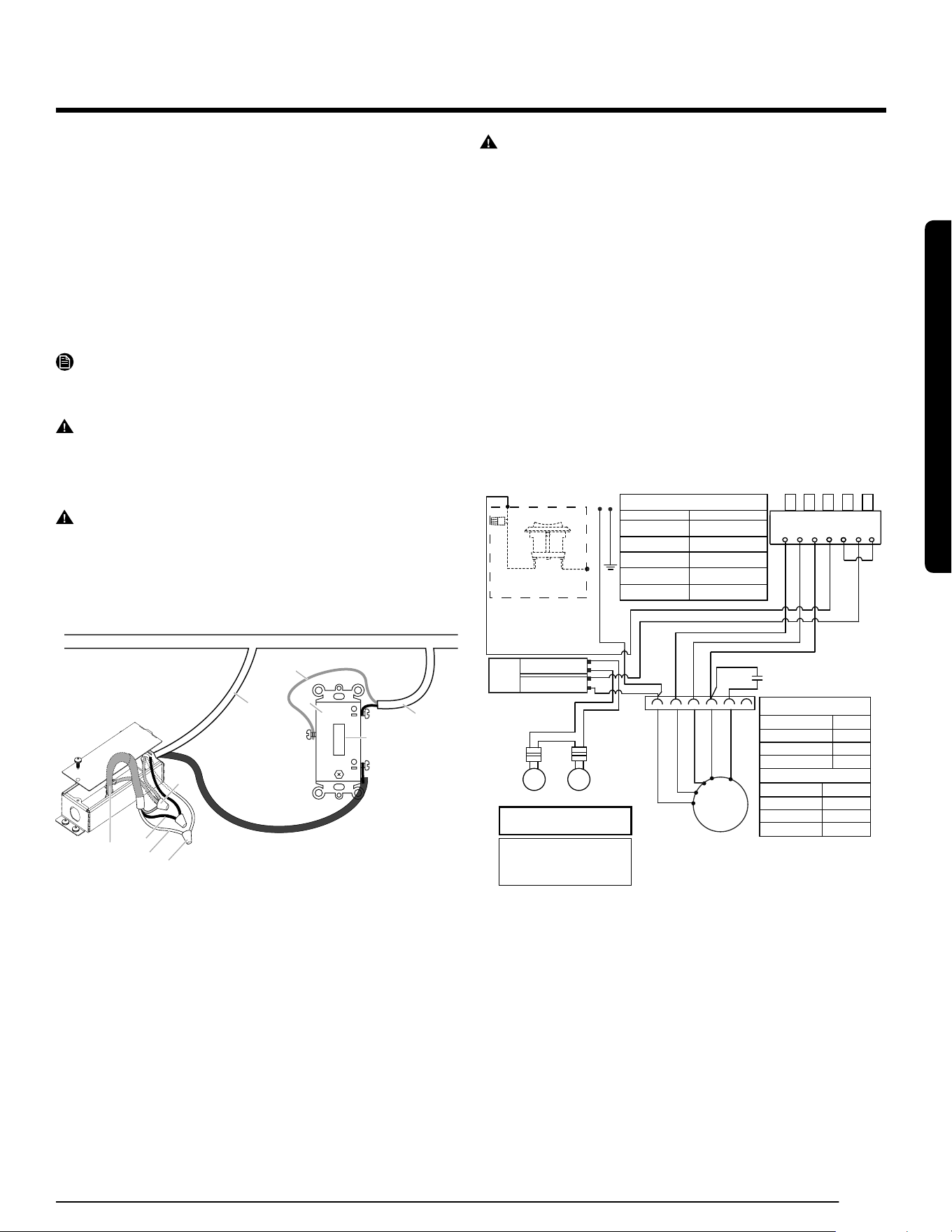
A. Range Hood Cable
B. UL listed wire connector
C. White wires (N)
D. Black wires (L)
E. Green (or bare) and
yellow-green ground
F. UL listed switch
G. Home power supply cable
H. Deep single gang switch box
WARNING
To avoid re or electrical shock, turn off power at the circuit breaker
panel or fuse box. Conrm that the power is off before wiring.
1. MOUNT THE SWITCH BOX . Install a 3½” deepsingle gang switch
box
1. ATTACH THE POWER CABLE. Clamp wiring to the switch box
and unit using an appropriate clamp. Provide 6” leads inside the box
and fan for easier wiring.
2. CONNECT THE WIRING. General instructions:
• Make sure both the switch box and the appliance are properly
grounded.
• Make sure the ground wire is securely fastened to the control’s
ground screw. Tighten the ground screw.
• Use proper wire nut sizes for the number and size of the wires.
• For push-in and screw terminals: Use min. #14 AWG solid copper
wire only.
• Tighten the screw terminals.
• Make electrical connections following the appropriate diagram.
For supply connection
use wires suitable
for at least 75° (167°F)
M
S15
8uF
YEL
WHT (SPEED 1)
YEL (LAMP)
BLK (SPEED 3)
BLK (LINE)
BWN (SPEED 1)
BWN
BWN
RED (SPEED 2)
GREY (SPEED 3)
GRY (SPEED 2)
RED (COMMON)
WHT
N
1
2
3
4
5
6
LED
LED
GND
YEL/GRE
WHT
WHT
BLK
BLU
BLK
RED
MOTOR CHARACTERISTICS
POWER SUPPLY
FREQUENCY
AMPERAGE
WATTAGE RATING
120 VAC
60 Hz
0,9 ±10% A
110 w
MOTOR RESISTANCE
RED - BROWN
RED - BLACK
RED - GREY
RED - WHITE
27.5
55.7
86.8
117.7
SEL0168627
>85
-1.5
+1.5
-1
+1
0÷85
27/10/20
Luis Salazar
29/04/20
PRINTING AREA
(101.6X101.6mm)
RELEASED
* DO NOT PRINT DASHED LINE
Schema elettrico / Wiring diagram
Carta metallizzata 101.6x101.6 / Metallic Sticky Paper x
SEL0168627
Nero / Black
3:2
PIRITE SAMSUNG
PUSH BUTTON SWITCH
3 2 1 L L La M
BLU
PUSH BUTTON SWITCH OPERATION
FUNCTION
OFF
LAMPS
LOW SPEED
MED SPEED
HIGH SPEED
POSITION
NO CONNECTION
(L-4)
(L-1)
(L-2)
(L-3)
BLUE- YELLOW
BROWN- WHITE
BROWN- RED
BROWN- BLACK
INPUT: 120VAC
+
-
OUTPUT:700mA(2-15VDC)
LED DRIVER
BK
For ADA compliance add these
elements during the installation
Remote Switch
L
BK
L
3. MOUNT THE CONTROL IN THE SWITCH BOX. Tuck wires into
the switch box and fasten the control to the box using the attached
screws.
4. ATTACH THE SWITCH PLATE. Fasten the switch plate to the control
using the short screws from the parts bag.
Loading ...
Loading ...
Loading ...