Loading ...
Loading ...
Loading ...
English 11
Installation Instructions
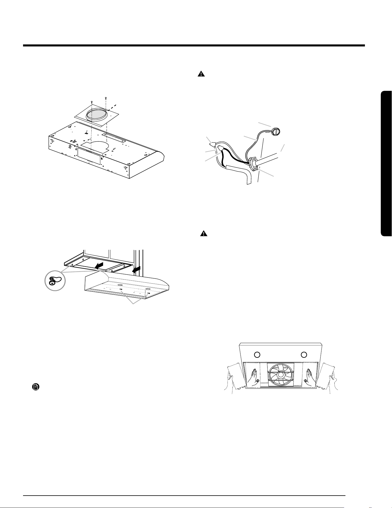
7" (17.8 cm) Round Vent Mounting Plate
1. Using (2) short Phillips head screws, install the 7" (17.8 cm) round
vent mounting plate (A) over the vent knockouts removed in previ ous
step. Position the wide ange (B) to the front. .
A
B
Mounting the Hood
1. Using 2 or more people, lift the hood into nal position. Feed enough
electrical wire through the ½” UL listed or CSA approved strain relief to
make connections in the terminal box. Tighten the strain relief screws.
2. Position the range hood so that the large end of the keyhole slots are
over the mounting screws. Then push the hood toward the wall so
that the screws are in the neck of the slots. Install the .5 cm x 4.5 cm
mounting screws in drywall anchors.
A
B
A. Mounting screws (4)
B. Security screws
3. Tighten the mounting screws, making sure the screws are in the
narrow neck of slots.
4. Tighten the security screws to the wall.
5. For direct wire installations, run the home power supply cable
according to the National Electric Code or CSA standards and local
codes and ordinances. There must be enough wiring from the fused
disconnect (or circuit breaker) box to make the connection in the
range hood electrical terminal box.
NOTE
Do not reconnect power until the installation is complete.
OPTIONAL: If you prefer, bend the rear tabs against the rear of the
range hood and attach to the wall using #8-18 x
5
/
8
" (4.2 x 16 mm)
truss-head screws.
Connect Vent System
1. Connect the vent work to the range hood.
2. Seal joints with vent clamps or duct tape to make secure and airtight.
3. Check that the backdraft dampers work properly.
Electrical Connection
WARNING
ELECTRICAL SHOCK HAZARD.
DISCONNECT POWER BEFORE SERVICING. REPLACE ALL PARTS
AND PANELS BEFORE OPERATING. FAILURE TO DO SO CAN
RESULT IN DEATH OR ELECTRICAL SHOCK.
A
B
C
D
E
F
G
A. White wires
B. Black wires
C. UL listed wire connector
D. Green (or bare) ground wire
E. Homepower supply cable
F. UL listed or CSA approved
1
⁄2″
strain relief
G. Green ground screw
1. Run 3 wires - black, white, and green - according to the National
Electrical Code and local codes and ordinances, in
1
⁄
2
″ conduit from
the service panel to the junction box.
WARNING
ELECTRICALLY GROUND THE BLOWER. CONNECT THE GROUND
WIRE TO THE GREEN AND YELLOW GROUND WIRES IN THE
TERMINAL BOX. FAILURE TO DO SO CAN RESULT IN DEATH OR
ELECTRICAL SHOCK.
2. Connect the black wire from the service panel to the black or the red
in the junction box. Connect the white to white and green to green-
yellow.
3. Close and secure the junction box cover.
Completing the installation
1. Place the lateral panels by sliding them horizontally from the back of the
hood and then secure the brackets on the front.
2. Place the lters and check the operation of the hood.
• For vented installations: Install only the metal grease lter.
• For non-vented (recirculating) installations: Install both a
charcoal and metal grease lter.
If the range hood does not operate:
• Conrm that the circuit breaker is not tripped or the house fuse blown.
• Disconnect the power supply, and then check if the wiring is correct.
• To get the most efcient use from your new range hood, read the
“Range Hood Use” section.
• Keep these Installation Instructions and Use and Care Guide close to
range hood for easy reference.
Installation Instructions
Loading ...
Loading ...
Loading ...