Loading ...
Loading ...
Loading ...
LOCATION OF WOOD LATHE
The lathe should be positioned so that neither the operator
nor a casual observer is forced to stand in line with the spin-
ning chuck or workpiece.
WARNING: The lathe must be damped mrbolted securely to
work bench. An unbalanced workplace will cause the lathe to
shake and tip over.
MOUNTING LATHE TO BENCH
• Dr!l[ four %"holes through the top of the bench as shown
in the following illustration:
• Position lathe over the holes and feed 31_,,"f_at head screws
(not supplied) through holes in lathe bed.
• Secure from underneath with fiat washera, lock washers
and hex nuts (not supplied).
_....,e-- 173/="maXl---a,.-___
5V[I l'l I
Figure 1 - Location of Mounting Holes
Rtnt Of
Bench
REMOVAL OF SPUR CENTER FROM SPINDLE
• Toremove spur center from spindle, insert a Y4"wood
dowel or brass rod through the hole in the spindle. Hold
the center with one hand and tap the dowel or rod with a
hammen
REMOVAL OF BEARING CENTER FROM QUILL
Refer to Figure 42:
• Toremove bearing center from tai! stoc_kqunl, loosen
handle (Key No. 34) and turn adjustment nut (Key No. 44)
t_vcardsfront of lathe bed.
POWER SOURCE
WARNING: Do notconnectwood lathe to the power source
until all assernb!y steps have been completed.
The motor isdesigned foropera,on onthe voltage and frequency
specil_ed.Normalloads will be handled safely onvoifages not
more than 10% above or below specked voltage.Running the
unitonvoltageswhich are notwithinrange may cause overheat-
ingandmotor burn-out. Heavy loads require that voltage at motor
terminals be no less than the voltage specified on nameplate.
• F_:_versupply to the motor iscon_'olledby a single pole locking
roci<erswitch.Remove the keytoprevent unauthorizeduse.
GROUNDING INSTRUCTIONS
WARNING: Improper connection of equipmentgroundingcon-
ductor can result in the dsk of elec_icel shock.Equipment should
be groundedwhile in use to protect operator from elec#'icefshock.
Check with a qualified electrician if grounding instruclJons
are not understood or if in doubt as to whether the tool is
properly grounded.
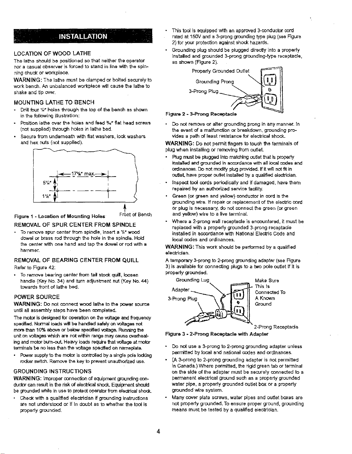
• This tool is equipped with an approved3-conductor cord
rated at 150V and a 3-prong grounding type plug (see F]gure
2) for your protection against shock hazards.
• Grounding plug should be plugged directly into a properly
installed and grounded 3-prong grounding-type receptacle,
as shown (Figure 2).
Propedy Grounded Outlet _-'------_'_
Grouodingprong 4@11
3-Prong Plug
Figure 2 -3-Prong Receptacle
• Do not remove or alter grounding prong in any manner. In
the event of a malfunction or breakdown, grounding pro-
vides a path of least reeistance for elec'o-ical shock.
WARNING: Do net permit fingers to touch the terminals of
plug when installing or removing from outlet.
Plug must be plugged into matching outtat that is properly
installedand groundedin accordancewith nillocal codes and
ordinances. Do not modify plug provided. Ifit will notfit in
ou_et, have proper outtat installed by a qualiSed electrician.
Inspect tool coeds periodicallyand if damaged, have them
repaired by an authorized service fectldy.
Green (or green and yellow) conductor in cord is the
grounding wire. If repair or replacement of the electric cord
or plug is necessary, de not connect the green (or green
and yellow) wire to a live terminal
- Where a 2-prong wall receptacle is encountered, it must be
replaced with a properly grounded 3-prong receptacle
installed in accordance with National Etacfric Code and
local codes and ordinances.
WARNING: This work should be performed by a qualified
etact]ictan.
A temporary 3-prong to 2-prong grounding adapter (see Figure
3) is available for connecting plugs to a two pete outlet ff it is
properly grounded.
Grounding Lug Make Sure
Adapter Donnected To
Ground
2-Prong Receptacle
Figure 3 - 2-Prong Receptacle with Adapter
- Do not use a 3-prong to 2-prong grounding adapter unless
permitted by local end national codes and ordinances.
• (A 3-prong to 2-prong grounding adapter is not permitted
in Canada.) Where permitted, the rigid green tab or terminal
on the side of the adapter must be securely connected to a
permanent electrical ground such as a properly grounded
water pipe, a properly grounded outlet box or a properly
grounded wire system.
• Many cover plate screws, water pipes and outlet boxes are
not properly grounded. To ensure proper ground, grounding
means must be tested by a qualified electrician.
4
Loading ...
Loading ...
Loading ...