Loading ...
Loading ...
Loading ...
8
© 2021 United States Stove Company
4. Carefully cut intake/exhaust thru hole in exterior
wall thru to the outside (see “Vent Clearances”
section to ensure proper installation).
5. Insert 1/4” concrete wall anchors into the pilot
holes and make sure that the anchors are
seated ush with the concrete surface.
6. Align the wall plate with the anchors. Place
washers over the screw holes in the wall plate,
insert 1/4” x 2” lag bolts through the washers,
and then tighten the lag bolts until the washers
are pulled rmly against the wall plate and the
wall mount is pulled rmly against the exterior
wall.
B. Step 2 - Mounting the Heating Unit to the
wall plate
Note: The Heating Unit is heavy. You will need
assistance with this step.
1. Before hanging the unit on the wall bracket
the exhaust/intake transition piece needs to
be mounted on the back of the unit. On the
exhaust side of the unit there is a ring that is
held on with four screws, it needs to be removed
so the transition piece can be mounted. Use the
supplied Phillips head self-tapping screws to
attach the transition piece. Once the transition
piece is mounted the ring on the outside of the
unit can be put back on.
2. After you have your hole cut and mounting
bracket secured to the wall, the heating unit
can hung on the bracket.
3. Align /intake with the hole in the wall mounting
bracket and thimble, and carefully insert heating
unit. Tilt the top of the heating unit towards the
wall and lower onto the wall mounting bracket
making sure that the right and left bracket
mounted to the unit hooks over the top of the
wall mounting bracket. Allow the Heating Unit
to pivot downward becoming parallel to the
wall mounting bracket. Lift the unit up and the
lower hooks will engage with the mounting
bracket.
4. Once the unit is securely hanging on the wall
mounting bracket there are two 7/16” head bolt
on the bottom of the bracket that need to be
tightened down to lock the unit to the bracket.
5. Once the unit is locked down the exhaust/
intake pipe can be attached to the unit on the
outside of the house.
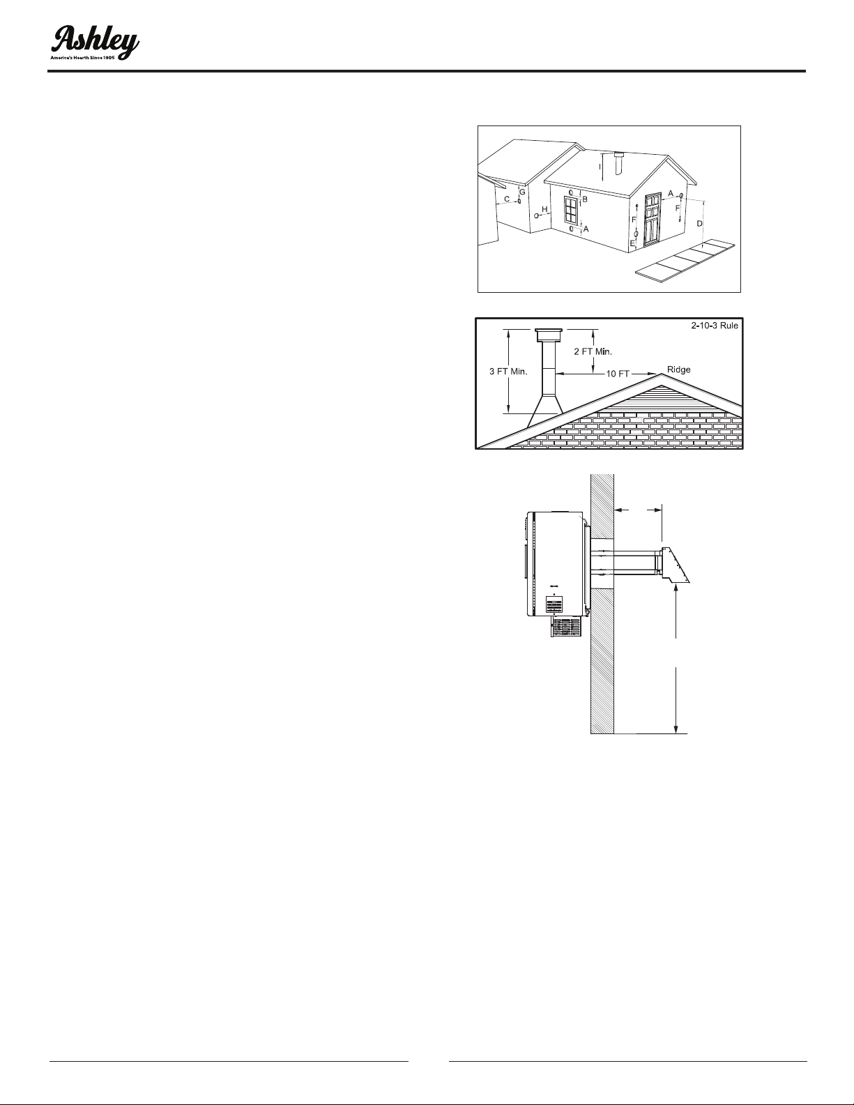
VENT TERMINATION CLEARANCES
6”
(152 mm)
24”
(609 mm)
A. Minimum 4-foot [1.2m] clearance below or
beside any door or window that opens.
B. Minimum 1-foot [0.3m]clearance above any
door or window that opens.
C. Minimum 2-foot [0.6m] clearance from any
adjacent building.
D. Minimum 7-foot [2.1m] clearance from any
grade when adjacent to public walkways.
E. Minimum 2-foot [0.6m] clearance above any
grass, plants, or other combustible materials.
F. Minimum 4-foot [1.2m] clearance from an forced
air intake of any appliance.
G. Minimum 2-foot [0.6m] clearance below eves or
overhang.
INSTALLATION
Loading ...
Loading ...
Loading ...