Loading ...
Loading ...
Loading ...
ASSEMBLY INSTRUCTIONS
12
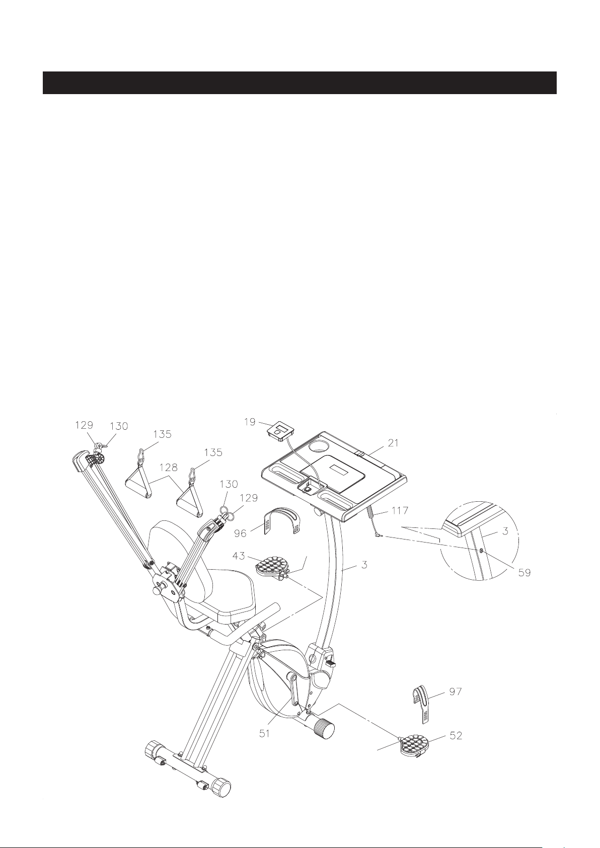
STEP 12
NOTE: The RIGHT PEDAL(52) has an R stamped on the end of the pedal shaft. The RIGHT PEDAL(52) has
right hand threads and is tightened by turning clockwise. The LEFT PEDAL(43) has an L stamped on the end
of the pedal shaft. The LEFT PEDAL(43) has left hand threads and is tightened by turning counterclockwise.
Thread the RIGHT PEDAL(52) to the RIGHT CRANK(51) as shown. Tighten the pedal securely. The
shoulder of the PEDALS(43, 52) should be in contact with the CRANKS(44, 51) when securely tightened.
Select the RIGHT PEDAL STRAP(97) which has an R marked on the bottom side of the strap. Snap the
three hole end to the inside edge of the RIGHT PEDAL(52). Snap the other end to the outside edge of the
RIGHT PEDAL(52) with the R mark on the bottom of the RIGHT PEDAL STRAP(97). Select adjustment
holes which allow your foot to be easily removed from the pedals.
Repeat on the left side in order to attach the LEFT PEDAL(43) to the LEFT CRANK(44) and snap the LEFT
PEDAL STRAP(96) to the LEFT PEDAL(43).
STEP 13
Refer to the illustration and detail view. Pry the METER(19) from the DESKTOP(21). Install two AAA batteries
into the METER(19), the batteries are not included. See page 14 for detailed battery installation instructions.
Press the METER(19) back to the DESKTOP(21). Plug the CONNECTION WIRE(117) into the socket of
the SENSOR WIRE(59) which located at the front of the UPRIGHT(3).
STEP 14
Attach the HAND STRAPS(128) to TENSION CORDS(129, 130) with the HOOK(135) on both sides.
Shoulder
Shoulder
Loading ...
Loading ...
Loading ...