Loading ...
Loading ...
Loading ...
ASSEMBLY INSTRUCTIONS
11
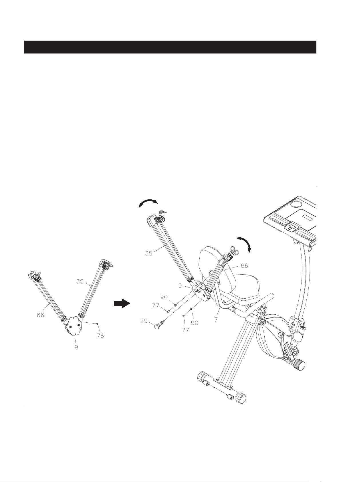
STEP 10
Refer to illustration B. Screw the SOCKET HEAD BOLT(M6x1x12mm)(76) into the inner side of the LEFT
RESISTANCE ARM(35).
STEP 11
Assemble the RESISTANCE ARMS(35, 66) by attaching the ARM BRACKET(9) to the BACK FRAME(7) with
SOCKET HEAD BOLTS(M8x1.25x15mm)(77) and LOCK WASHERS(M8)(90). Screw the ADJUSTMENT
PIN(29) into the ARM BRACKET(9), and make sure the pin is inserted into one of the adjustment holes in
the RIGHT RESISTANCE ARMS(66). The angle between two RESISTANCE ARMS(35, 66) is adjustable by
inserting the ADJUSTMENT PIN(29) into a dierent adjustment hole. Pull the ball knob of the ADJUSTMENT
PIN(29) to adjust.
B.
Loading ...
Loading ...
Loading ...