DLE5911W
DLE2511W
andGasD
DLG5911W
DLG2511W
Thank you for buying an LG dryer.
Please read your owner's manual carefully, as it provides
instructions on safe installation, use, and maintenance.
Retain it for fialure reference and record the model and serial
Jm_rs of your dryer.
L
_mpletamente AuIomAti_ _.
cuidado_mente, ya que
bre la _ura instalaci6n, manejo
futuras refe4_encias,archive
secadora.
SAFETY INSTRUCTIONS .............................................................................................................................................. 2-5
BEFORE USING YOUR NEW DRYER .........................................................................................................................................................2
IMPORTANT SAFETY iNSTRUCTiONS ...................................................................................................................... 3
LG DRYER WARRANTY _.....................................................................................................................................................................................5
INSTALLATION INSTRUCTIONS ................................................................................................................................ 6-21
iNSTALLiNG THE DRYER ..................................................................................................................................................................................7
DOOR REVERSAL PROCEDURE ............................................................................................................................ 10
MANUFACTURED (MOBILE) HOME iNSTALLATiON ...................................................................................................................11
ELECTRICAL REQUIREMENTS - ELECTRICAL DRYER ........................................................................................ 12
ELECTRICAL REQUIREMENTS - GAS DRYER ....................................................................................................................................16
GAS REQUIREMENT .......................................................................................................................................... 18
EXHAUST REQUIREMENTS ............................................................................................................................................................................19
OPERATION INSTRUCTIONS ................................................................................................................................... 22-28
USER • MAiN • TENANCE .................................................................................................................................................................................22
FEATURES AND BENEFITS ...................................................................................................................................... 23
TROUBLESHOOTING TIPS ...................................................................................................................................... _-_
BEFORE YOU CALL FOR SERVICE ......................................................................................................................... 28
CUSTOMER SERVICE ............................................................................................................................................... _-31
SERVICE TELEPHONE NUMBER ............................................................................................................................. 30
LG DRYER LiMiTED WARRANTY. ........................................................................................... 31
Please read this manual It wi]] help you install and operate
your new LG dryer in the safest and most economical way.
Use the space below to record the model number
and seria] number of your new LG dryer.
if you need more information about the care and operation of
LG appliances, call your nearest LG store. You will need
the complete model and serial numbers when requesting
information.
Your dryer's model and serial numbers are located on the
Mode] and Seria] Number Plate.
LG SERVICE Call : 1-877-714-7486
Model No.
Serial No.
Date of Purchase
2
ALLINSTFIJ ONS I:E UgNG.
WARNING!
your mfety, tl_ tions in this n_n_l m'_st _ followed. Toreduoe the
risk of fire _ sh_, _ to _vent datrmge, persop._l injury,
or _th when using you,, applianoa, follow basic precaution_ including the following.
JI Do not store or u_ gasoline or other
flammable vapors and liquids in the
vicinity of this or any other
JI Installation and _rvice must be
performed by a qualified installer or
service agency.
WHAT TO DO IF YOU SMELL GAS:
m Do not try to light a match, or cigarette,
or turn on any gas or electrical
JI Do not touch any electrical switches.
Do not use any phone in your building.
JI Clear the room, building or area of all
il Immediately call your gas supplier
from a neighbor _ phone. _llow the
gas supplier's instructions carefully.
JI If you cannot reach your gas supplier,
call the fire departmenL
rnia Safe Drinking _lter and Ibxic ement Act
This act rcquircs the governor of California u) publish a list of substanccs known to thc s|ate u) cause canccr, birlh
defects or other mpr_xluctive harm and requires busines_s to warn customers of potcnfial ext×)sure to such substances.
(;as appliances ca'l cause minor exit)sure m four of thcse subs|rances, namely benzene, carbon monoxide, fonnaldehyde
and _)ol, cau_:d primarily by the incomplete combuslion of natural gas or LP fuels.
ProF_rly adjustcd drycrs will minimize combustion. ExF_)surc m these snNlances can be minimized further by Ox)perly
venting _le dqer to the outdoors.
3
IMPORTANT SAFETY INSTRUCTIONS
WARNING - "I_,)reduce the risk of fire, electric Sh(_zk, or
i_my' to t_rsons when using your _)pliance, follow basic
precautions, includirig the lbllowirig:
I) Re;gJ all instructions beli)re using the appliance.
2)
3)
Do not dry a_:icles that have come into contact with
gasoline, dry=clcarfing _)lvents, or other flammable or
explosivc substances, as they give off w_po-_ Gmt could
ignite or expk_de.
Do not allow chil&'en to play on or in the appliance. Close
supervision of children is necessary when using the
appliance.
4) Beti}re the appliance is removed ti'om service or
di_arded, remove the d(×)r to the drying compartment.
5) Do not rcach into _ae appliance if the drum is moving.
6) Do not install or store lhis appli_mce where it will be
exposed to the weather.
7) Do nol: tamt_r with controls.
8) Do not rcpair or replace any part of the appliance or
attempt any servicing unless st'_cifically recommend_ in
the user-maintenance instructions.
9) Do not use heat to dry articles containing tkmm mbl_r or
similarly textured rnb_cr-like mate:rials.
10) Clean lint s_:reen _l_orc or alter each load.
11)
12)
13)
Keep a_2a around the exhaust opening and adjacent
snrroundi_vg areas five from ihe accmnnlation of lint,
dust, and di_l.
The interior of the _pliance and exhaust duct should be
cleaned periodically by qu;dified service personnel.
J-N)not place items cxt×)sed m cooking oils in your dryer.
Items contaminat_ with cooking oils may contribute to
a chemical _actiou that could cau_a_ a load to catch tim.
14) Do not use fabric sofiners or products to eliminate static
unless recommended by the mmmtimmrer of file ti_bric
soflner or product.
SAVE THESE INSTRUCTIONS
For a grounded, cord-connected appliance:
GROUNDING INSTRUCTIONS
This appliance must _ grom'lded. In the event of
maltunction o:r breakdown, grounding will reduce the risk of
electric shock by t)roviding a path of least :msist_mce for
electric curJ'ent. This appliance is equipped with a cord
having _mequipment-grounding couductor _md a gronnding
plug. The plug must _ plumed iuto an appropria|e ou|let
that is prot_rly installed ;rod grounded in accordalme with all
local c{_des and ordinances.
WARNING - ImprotK:r conneclion of the equipment-
gr(mnding condncmr can result in a risk of electric shock.
Check with a qualified electrician or service Fmrsxm if you
are in doubt as to whether the appliance is properly
grounded.
Do not modify" the plug provided with the appliance: if it will
not fit the ontleL have a proper outlet installed by, a qualified
electrician.
For a permanently connected appliance:
GROI1NIIING INSTRUCTIONS
This appliance must Nz connected to a grounded metal
_rmanent wMng system. Alternatively, an equipment-
gr(mnding conductor must _ run with the circuit conductors
and connected to the equipment-grounding terminal or lead
on the appli_mce.
4
_1 One Year Warra_ on M_ni_l a_ Be_r_l
For one year from the date of purchase, if this dryer is
installed and operated according to the instructions in
this manual LG will repair or replace any of its
mechanical or electrical parts if they are defective in
material or workmanship.
NO_: Exhausting your dryer with a plastic vent may
void this warranty. Refer to section on Dryer Exhaust
Warranty _i_n
If the dryer is subjected to other than private family
use, all warranty coverage is effective for only 90
days.
Warranty service is available by contacting your
nearest LG Service Center in the United States.
www.LGESERVICE.COM
This waranty applies only while this dryer is in use in
the United States.
This warranty gives you specific legal rights, and you
may also have other rights which vary from state to
state.
& You,A vioe
S_aple sales dip _ canceled _ here.
Proof of the original tmrchase date is uceded to oblaiu service under the wammty.
_R YOUR _O_S
Write _ _ ap.d serial numbers here:
#
#
_D THIS MANb¼L
Inside you will find many helpful hints on how to use and maintain ),'our dryer properly. Just a little
t)reven|ive care on your part can save you a great deal of time _mdmoney over the life of your dryer.
IF YOU N_
You'll find many answers to comm(m problems in the Troublesh(×_fing Tit)s section. It"you review our
chaal of Troublesh(×)ting Tips first, you may no! need to call lk)r servicc.
If you do need _rvice, yon can relax knowing hel t) is only a phone call away. A list of toll-fi'ee customer
service nmnbers is includcd in the back section. In the IJ.S., you can always call the I11; Answer Center.
(SERVICE Call No. 1-877-714-7486)
5
t_
i
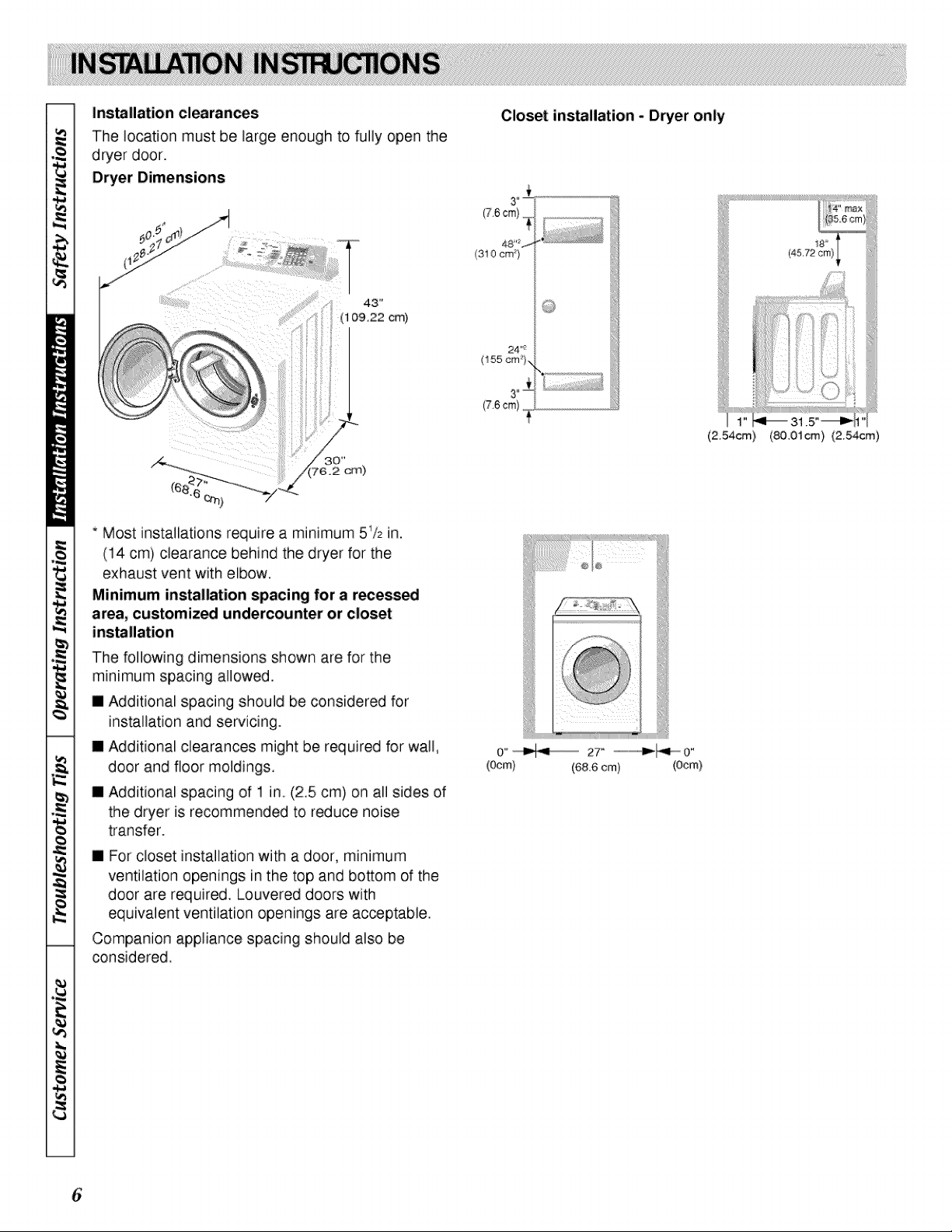
Installation clearances
The location must be large enough to fully open the
dryer door.
Dryer Dimensions
Closet installation - Dryer only
(310 era}
43 _
(1 09.22 cm)
(76 cm}....
(2,54cm) (80,01cm} (2,54cm)
* Most installations require a minimum 5_/= in.
(14 cm) clearance behind the dryer for the
exhaust vent with elbow.
Minimum installation spacing for a r_ess_
area, customized undercounter or closet
installation
The following dimensions shown are for the
minimum spacing allowed.
[] Additional spacing should be considered for
installation and servicing.
[] Additional clearances might be required for wall,
door and floor moldings,
[] Additional spacing of 1 in, (2,5 cm) on all sides of
the dryer is recommended to reduce noise
transfer.
[] For closet installation with a door, minimum
ventilation openings in the top and bottom of the
door are required, Louvered doors with
equivalent ventilation openings are acceptable.
Companion appliance spacing should also be
considered.
o"_ 27......................................._ o"
(Ocm) (68.6 cm) (Ocm)
6
Step I : Position and Level the Dryer
l:or fu_her assistance refer to section on Location
Requirements.
Place the dryer in lx)sition, and adjust the legs until the
dryer is level :fron_side: to side and fi_mt to back,
[vvel :fl_×_r: Maximum slope under emire dwcr should
not be more tlmn 2.5cm (1 inch), If slope is greater than
2.5 cm (I inch), clothes may not tumNe proFvfly and
_mtomatic sensor cycles may not ot_mte correctly if
dryer is not level,
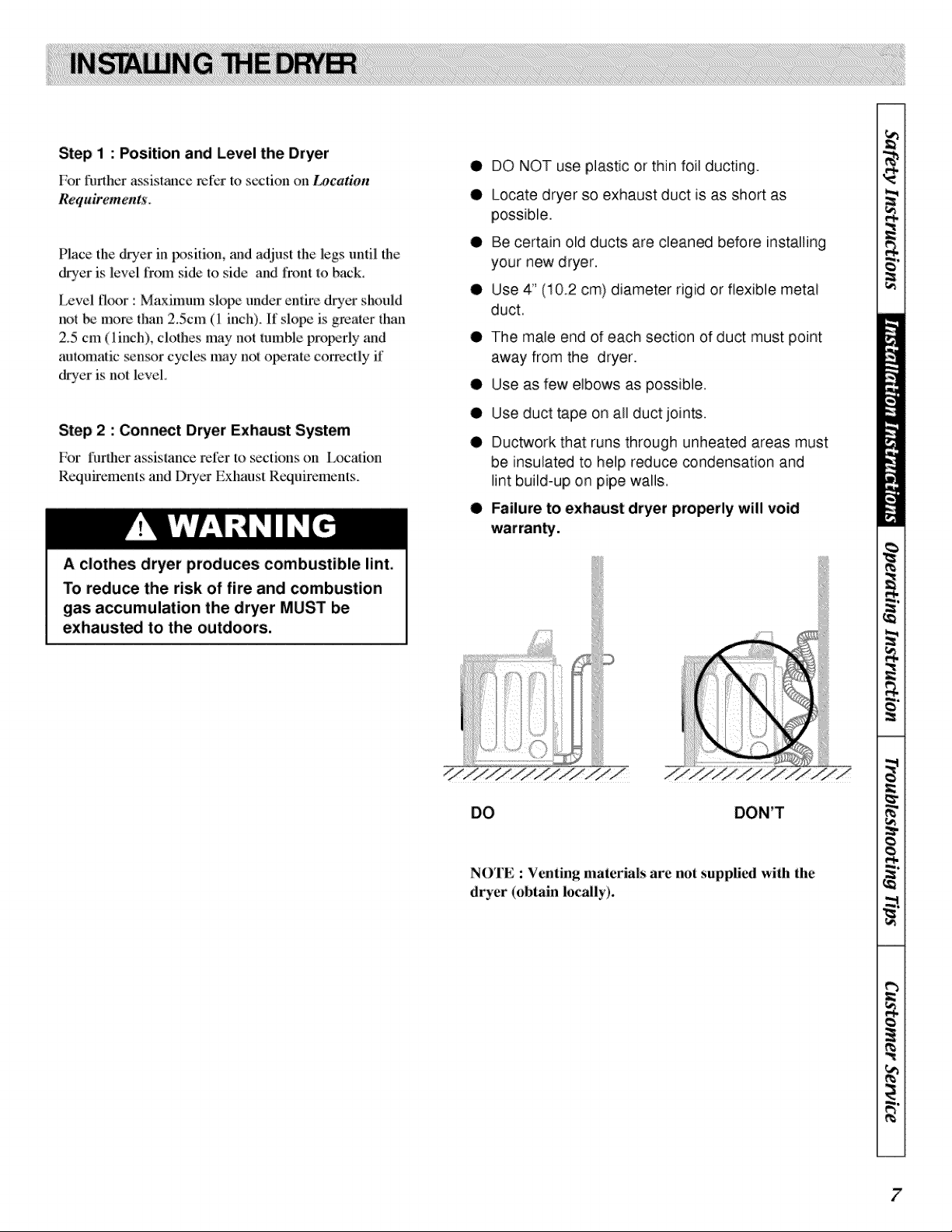
Step 2 : Conn_t Dryer Exhaust System
For t!urther assistance refer to _ctions {m Ix)cation
Requirements and Dryer Exhaust Requirements.
• DO NOT use plastic or thin foil ducting.
• Locate dryer so exhaust duct is as short as
possible.
• Be certain old ducts are cleaned before installing
your new dryer.
• Use 4" (10.2 cm) diameter rigid or flexible metal
duct.
• The male end of each section of duct must point
away from the dryer.
• Use as few elbows as possible.
• Use duct tape on all duct joints.
• Ductwork that runs through unheated areas must
be insulated to help reduce condensation and
lint build-up on pipe walls.
• Failure to exhaust dryer properly will void
A clothes dryer produces combustible lint.
To reduce the risk of fire and combustion
gas accumulation the dryer MUST be
exhausted to the outdoors,
NOTE : Venting materials are not supplit_l with the
dryer (obtain locally).
i
I
_a
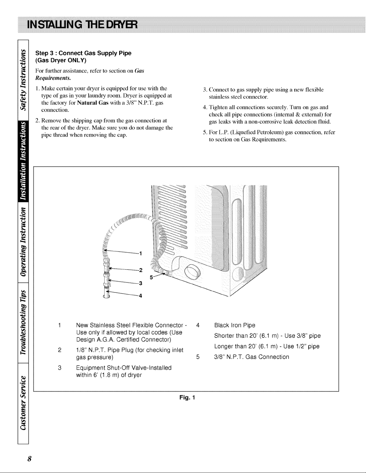
Step 3 : Conn_t Gas Supply Pi_
(Gas Dryer ONLY)
For l!u_lher assistance, relL_rto _ction on Gas
Requirements.
I. Make ceri:ain your dryer is equippvd fi_ruse with lhe
l:ypeof gas in your laundry room_ Dryer is equiplyad at
the tTml:OD,:liarNaiural Gas with a 3/8" N.P.T. g_s
connection.
2. Remove the shipping cap fix)m ihe gas connection at
ihe rear of the dryer. Make sure you do not damage the
pipe i:h:madwhen removing the cap.
3. (onnect to gas supply pipe using a new flexible
stainless sled connector.
4. Tighten all conneclious _:curely. 'l'um on gas and
check all pipe couneclions (internal & external) for
g_s leaks wilh a non-corrosive leak deiectkm fluid.
5. For L.P. (Liquefied Pe:troleum) gas conneciion, refer
l:o section on Gas Requiremems.
2
3
New Stainless Steel Flexible Connector -
Use only if allowed by local codes (Use
Design A.G.A. Certified Connector)
i/8" N.P.T. Pipe Plug (for checking inlet
gas pressure)
Equipment Shut-Off Valve-Installed
within 6' (1.8 m) of dryer
Black Iron Pipe
Shorter than 20' (6A m) - Use 318" pipe
Longer than 20' (6.1 m) - Use 1/2" pipe
3/8" N.P.T. Gas Connection
Fig. 1
8
Step 4: (Electric Dryer Only) Connect
Electrical Plug
For furlher assistance refer to section on Electrical
Requirements.
IMPORTANT : U_ only a new U.L. li_t,d No. 10
(copper wire only) three conductor _)wer supply
cord kit rat,._'l 240 Volts (minimum)30 Amper¢_
and labeled a:ssuitable for use in a clothes dryer.
NOTE : For more de_iled information on
conn_ction three=wire or four-wire plugs, refer to
s_etion on Fdectric Dryer Fdectrical Requirements.
NOTE : Four-wire cord is required for nmbile
homes or where c_'les do not __it grounding
Step 5: Wipe Out Inside of Dryer
Belbre using dryer for the fi_t timc, use an all-purpo_
clcancr, or a detc_Nent and water _lufion, and a damp
cloth to remove shipping dust from inside the drycr
drt|lll.
Heat Source Check
El_tric Dryers
Close the loading door and start the dryer in a heat
setting (ml_r to the ()perating Inslructions suppli_ with
the dryer). After the d_'cr has operated l;:_rfllree minutes,
the exhaust air or exhaust pipe should bc warm.
Gas Dryers
Close the loading door, start the dryer in a heat _tting
(rct;cr to the Operating Instructions supplied with the
dryer); the dryer will start, the igniter will glow red and
the main burner will ignite.
IMPORTANT : If all air is not purged out of the gas
line, the ga_sigmiter may go off before gas it is ignited.
If this happens, aher approximately two minutes the
igniter will ag_n attempt ga_ ignition.
Step 6: Plug In the Dryer
Refer to section on Electrical Requirements, ;rod
COlmect the dryer to an electrical l_)wer sxmrce.
Step 7: Check Installation
9
t_
I
_a
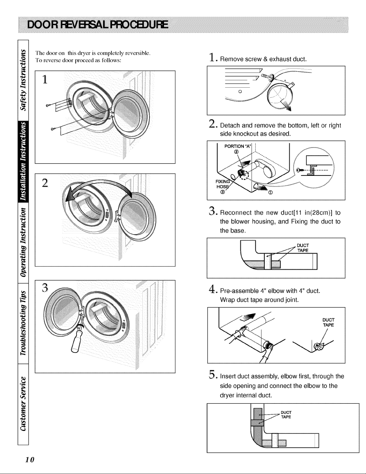
The door on this dryer is completely reve_ible.
To reverse d(×>rpr(meed as IMlows:
_ _ii__i_i_!i _iili_i
1. Remove screw & exhaust duct.
. Detach and remove the bottom, left or right
side knockout as desired.
PORTION "A_ i
@
®
O. Reconnect the new duct[11 in(28cm)] to
the blower housing, and Fixing the duct to
the base.
4, Pro-assemble 4" elbow with 4" duct.
Wrap duct tape around joint.
DUCT
TAPE
5. Insert duct assembly, elbow first, through the
side opening and connect the elbow to the
dryer internal duct.
DUCT
TAPE
...........i
1 0
IMPORTANT : InstMlation must conform to the
Manufactured Home Construction and Safety Standards,
Title 24 CFR, Part 32-80 or Standa_ CAN/CSA-Z240 MH.
The dryer can _ installed in a manuthctured (moNle)
home by lollowing these instructions:
1. IMPORTANT : Gas drye_ MUST be permanently
attached to the fl{n_rat the time of installation.
2 Elcctrical Connections (Ekctric Drycr Ordy) musl be a
4-wire connection.
3 Venting = Dryer MUST _ exhausled to the outdoors.
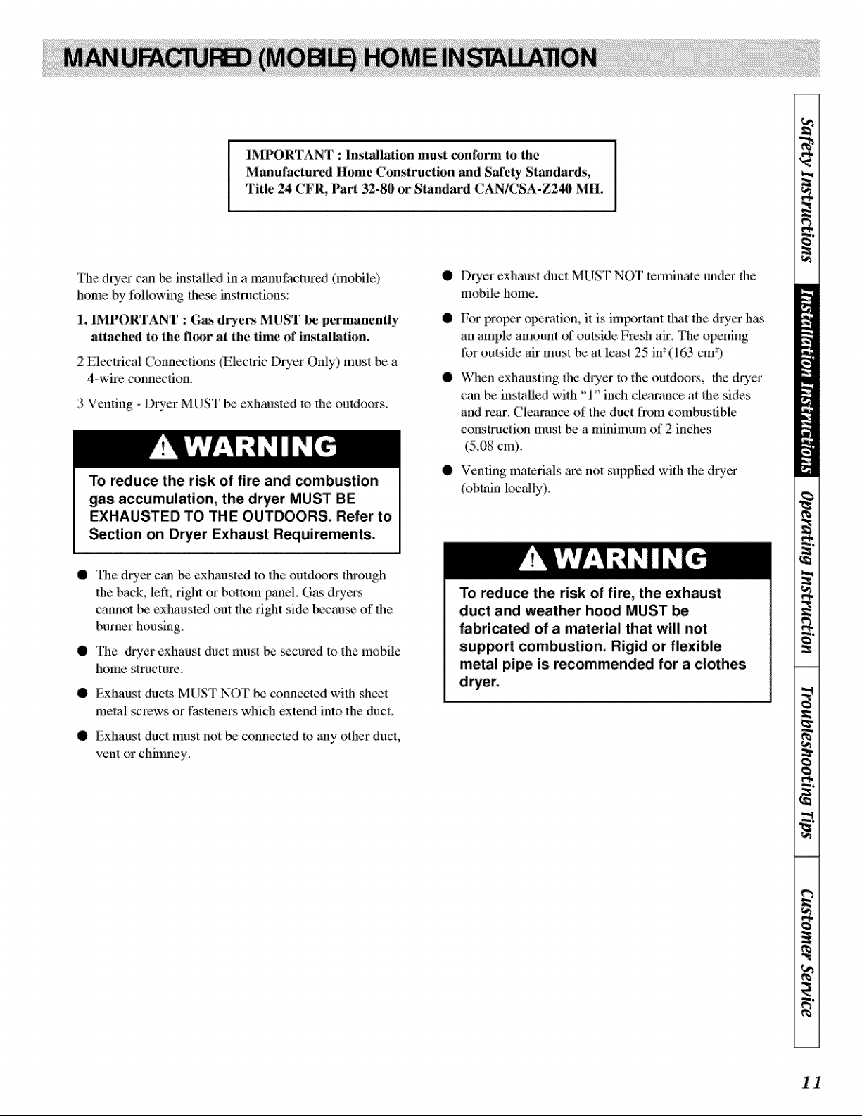
To reduce the risk of fire and combustion
gas accumulation, the dryer MUST BE
EXHAUSTED TO THE OUTDOORS. Refer to
_ction on Dryer Exhaust Requirements.
O
I)rycr exhaust duct MUST NOT tcnninme under lhe
lnobik: home.
For protmr olmmtion, it is im[_g}r|ant fllat file dryer has
an _m_ple amount of outside Fresh ai:r. The opening
liar outside air must _ at least 25 in_(1 (Gcm)
When exhzmsting the dryer to the outdoors, Ihe d:ryer
can _ installed with "1" inch clearance at fl_esides
and rear. Clem'ance of the duct from combustible
construction nmst b_ a minimum of 2 inches
(5.08 cm).
Venting nmk_als _e not supplied wifll the dryer
(obtain locally).
• The dryer c_m _ exh_mstcd to the outdCx)rs through
the back, left, right or bottom panel. Gas dryeJ_
cannot be exhausted out the right side bccau_ of _le
bumer housing.
• The d_3_er exhaust duct must be _curcd to _le mobile
home structure.
• Exhaust ducts MIST NOT be connected with sheet
metal screws or fasteners which extend into the duct.
• Exhaust dnct must not _ connected to _my other duct,
vent or chimney.
To reduce the risk of fire, the exhaust
duct and weather hood MUST be
fabricated of a material that will not
support combustion. Rigid or flexible
metal pipe is recommended for a clothes
11
E
im
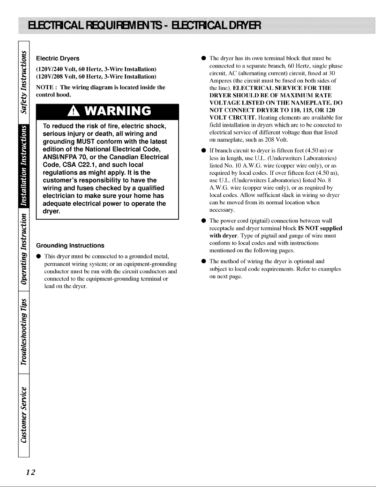
Electric Dryers
(120V/244) Volt, 60 Hertz, 3-Wire Installation)
(120V/208 Volt, 61) Hertz, 3-Wire Installation)
NOTE : The wMng diagram is located inside the
control h{md.
To reducd the risk of fire, electric shock,
serious injury or death, all wiring and
grounding MUST conform with the latest
_ition of the National Electrical Code,
ANSI/NFPA 70, or the Canadian Electrical
Code, CSA C22A, and such local
regulations as might apply. It is the
customer's responsibility to have the
wiring and fuses checked by a qualified
electrician to make sure your home has
adequate electrical power to operate the
Grounding Instructions
• This duer must be connected to a grounded metal,
permanent wiring system; or an equipmeni:-grounding
couduclor must _ run with the circuit conductors and
connected to the equipment-grounding terminal or
lead on the dryer.
O
O
O
O
The dryer has its own _cnninal block Ihat must be
connected to a sepa'ate branch, 60/lertz, single phase:
circuit, AC (alter_mting current) circuit, tilsed at: 30
Amperes (the circuit must be fused on N)th sides of
the liue). ELECTRICAL SERVICE FOR THE
DRYER SIIOI?LD BE OF MAXIMUM RATE
VOLTAGE LISTED ON THE NAMEPLATE. DO
NOT CONNECT DRYER TO 110, 115, OR 120
VOLT CIRCI!IT. Heating elements are available for
:fieldins{allation in dryers which are to be conected m
electrical service of dift;crent w)lmge than that listed
on namq_late, such as 208 Volt.
If branch circuit m dryer is fifteen i)et (4.50 m) or
less in length, u_= U.L. (Underwriters LaN_ratories)
listed No. 10 A.W.G. wire (copper wire only), or as
rcqaircd by local c(_es. If over fifteen tibet(4.50 in),
use [J.L. (Underwriters I.abomtories) listed No. 8
A.W.G. wire (copper wire only), or as l_.Nuiredby
local codes. Allow sufficient slack in wiring _ dryer
can be moved from its normal location when
necess_uLv.
The ln)wer cord (pigtail) conn_tion between wall
receptacle and dryer terminal block IS NOT supplic-d
with dryer. Type of pigtail and gauge of wire must
confom_ to local codes and with instructions
mentioned on the :li:)llowingpages.
The meth(x.t of wiring the dryer is optional and
subject to k_'a! c_e requirements_ Ret'er to examples
on next page.
12
Electrical Connection Options
if your home has: And you will _ Go to Section
connecting to
4-wire receptacle A UL listed, 120/240 4-wire connection:
(NEMATypei4°30R) volt minimum, 30 Power supply cord
amp, dryer power
supply cord*
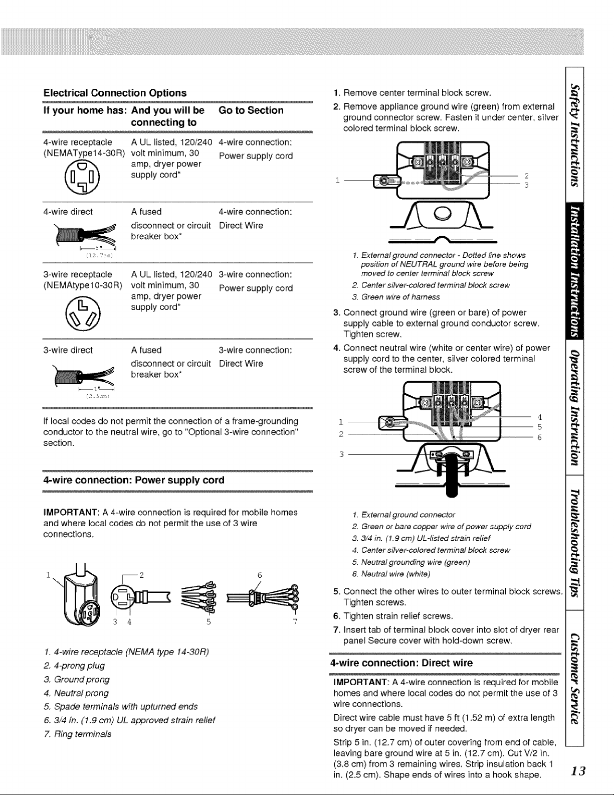
1, Remove center terminal block screw,
2. Remove appliance ground wire (green) from extemai
ground connector screw, Fasten it under center, silver
colored terminal block screw.
4-wire direct A fused 4-wire connection:
disconnect or circuit Direct Wire
x_ breaker box*
3-wire receptacle
(N EMAty pe 10-30 R)
A UL listed, i20/240 3owire connection:
volt minimum 30 Power supply cord
amp, dryer power
supply cord*
3-wire direct A fused 3owire connection:
disconnect or circuit Direct Wire
"_ breaker box*
if local c_es do not permit the connection of a frame,rounding
conductor to the neutral wire, go to "Optional 3°wire connection"
section.
4-wire connection: Power supply cord
IMPORTANT: A 4-wire connection is required for mobile homes
and where local codes d_ not permit the use of 3 wire
con nections,
3 4
1.4-wire receptacle (NEMA type 14-30R)
2, 4-prong plug
3, Ground prong
4, Neutral prong
5, Spade terminals with upturned ends
6. 3/4 in. (1.9 cm) UL approved strain relief
7, Ring terminals
1. External ground connector - Dotted line shows
position of NEUTRAL ground wire before _ing
moved to center terminal block _rew_-
2. Center silver-colored terminal block screw
3. Green wire of harness
3, Connect ground wire (green or bare) of power
supply cable to external ground conductor screw.
Tighten screw,
4. Conn_t neutral wire (white or center wire) of power
supply cord to the center, silver colored terminal
screw of the terminal block.
4
I5
--6
1. External ground connector
2. Green or bare copper wire of power supply cord
3. 3/4 in, (1,9 cm) UL-tisted strain relief
4. Center silver-colored terminal block screw
5. Neutral grounding wire (green)
6. Neutral wire (white)
5, Connect the other wires to outer terminal block screws
Tighten screws.
6, Tighten strain relief screws,
7. Insert t_ of terminal block cover into slot of dryer rear
panel Secure cover with hold-down screw
4-wire connection: Direct wire
IMPORTANT: A 4-wire connection is r_uired for mobile
homes and where local codes do not permit the use of 3
wire connections.
Direct wire cable must have 5 ft (i ,52 m) of extra length
so dryer can be moved if needed.
Strip 5 in, (12,7 cm) of outer covering from end of cable,
leaving bare ground wire at 5 in. (12.7 cm). Cut Vi2 in.
(3,8 cm) from 3 remaining wires, Strip insulation back i
in. (2.5 cm). Shape ends of wires into a h_k shape.
13
t_
E
I
When connecting to the terminal block, place the hooked
end of the wire under the screw of the terminal block (hook
facing right), squeeze hooked end together and tighten
screw.
%
1. Remove _nter terminal block screw.
2. Remove appliance ground wire (green) from external
ground connector screw. Fasten it under _nter, silver
colored terminal block screw.
3. Connect ground wire (green or bare) of power supply
cable to external ground conductor screw. Tighten
screw.
4
3_
2
1, External ground connector
2 Green or bare copper wire of power supply cord
3. 3/4 in. (1.9 cm) UL qisted strain relief
4. Center silver_lered terminal block screw
5, Neutral grounding wire (green)
6_ Neutral wire (white)
4. Place the hooked end of the neutral wire (white wire)
of power supply cable under the center screw of
terminal block (hook facing fighO. Squeeze hooked
end together. Tighten screw.
5. Place the hooked ends of the other power suppJy
cable wires under the outer terminaJ bJock screws
(hooks facing right). Squeeze hooked ends together.
Tighten screws.
6. Tighten strain relief screws.
7. Insert tab of terminal block cover into slot of dryer rear
panel Secure cover with hold-down screw.
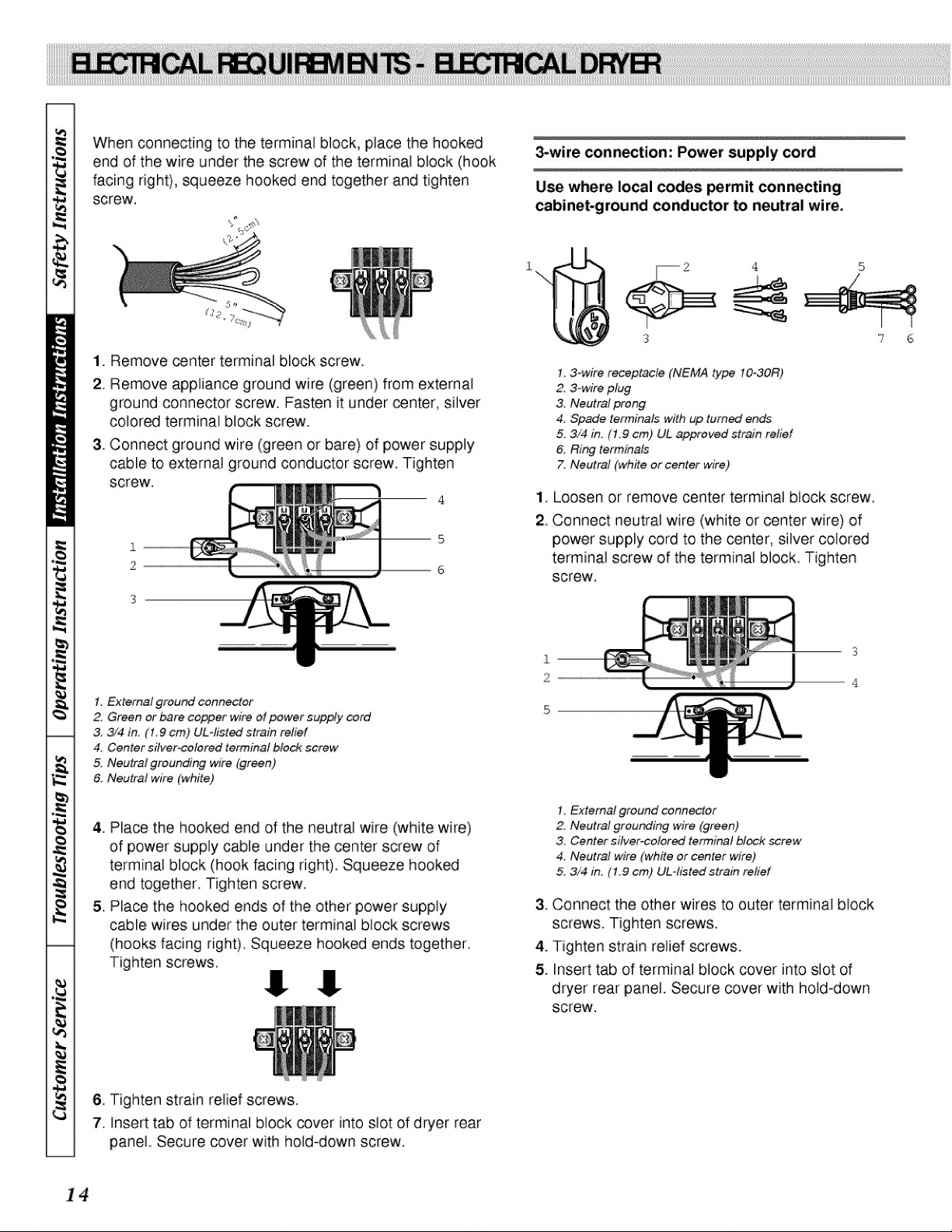
3-wire connection: Power supply cord
Use where local codes permit connecting
cabinet-ground conductor to neutral wire.
I, 3-wire receptacle (NEMA type 10-30R)
2. 3-wire plug
3. Neutral prong
4. Spade terminals with up turned ends
5, 3/4 in. (1.9 cm) UL approved strain retie/
6. Ring terminals
7. Neutral (white or center wire)
Loosen or remove center terminal biock screw.
Connect neutral wire (white or center wire) of
power supply cord to the center, silver colored
terminal screw of the terminal block. Tighten
screw.
3
I, External ground connecter
2. Neutral grounding wire (green)
3. Center silver-colored terminal block screw
4. Neutral wire (white or center wire)
5. 3/4 in. (1.9 cm) UL-listed strain relief
3. Connect the other wires to outer terminal block
screws. Tighten screws.
4. Tighten strain relief screws.
5. Insert tab of terminal block cover into slot of
dryer rear panel. Secure cover with hold-down
screw.
I #
3-wire connection: Direct wire
U_ where I_al c_es permit connecting
cabinet-ground conductor to neutral wire,
Direct wire cable must have 5 ft (1.52 m) of extra
length so dryer can be moved if needed.
Strip 3V2 in, (8.9 cm) of outer covering from end of
cable. Strip insulation back 1 in. (2.5 cm). If using
3-wire cable with ground wire, cut bare wire even
with outer covering. Shape ends of wires into a hook
shape.
When connecting to the terminal block, place the
hooked end of the wire under the screw of the
terminal block (hook facing right), squeeze hooked
end together and tighten screw.
%,"
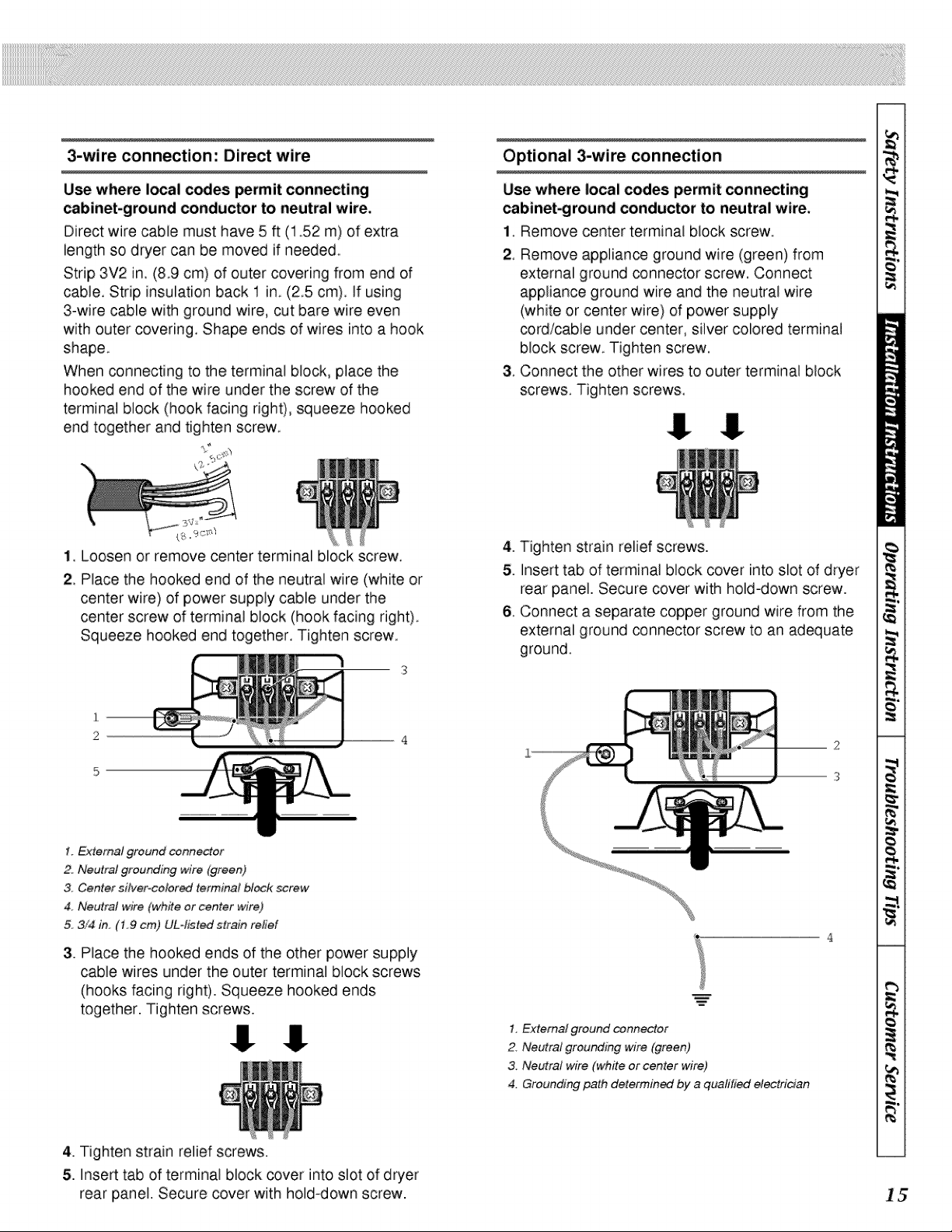
Optional 3-wire connection
Use where local codes permit connecting
cabinet-ground conductor to neutral wire.
1_.Remove center terminal block screw_
2, Remove appliance ground wire (green) from
external ground connector screw, Connect
appliance ground wire and the neutral wire
(white or center wire) of power supply
cord/cable under center, silver colored terminal
block screw. Tighten screw,
3. Connect the other wires to outer terminal biock
screws. Tighten screws,
, °9c _r'/
1, Loosen or remove center terminal block screw,
2, Place the hooked end of the neutral wire (white or
center wh°e) of power supply cable under the
center screw of terminat block (hook facing right),
Squeeze hooked end together, Tighten screw,
1. External ground connector
2, Neutral grounding wire (green)
3. Center silver-colored terminal block screw
4. Neutral wire (white or center wire)
5, 3/4 in. (1.9 crn) ULqisted strain relief
,
Place the hooked ends of the other power supply
cable wires under the outer terminal block screws
(hooks facing righ9. Squeeze hooked ends
together. Tighten screws.
4. Tighten strain relief screws.
5. Insert tab of terminal block cover into slot of dryer
rear panel. Secure cover with hold-down screw.
6 Connect a separate copper ground wire from the
external ground _nnector screw to an adequate
ground.
1. External ground connector
2. Neutral grounding wire (green)
& Neutral w_re (white or center wire)
4. Grounding path determin_ by a qualified electrician
4. Tighten strain relief screws.
5. Insert tab of terminal block _ver into slot of dryer
rear panel. Secure cover with hold-down screw. 15
tile
i
Gas Dryers
(120 Volt, 60 Hertz, with 3-Prong (;rounding Plug)
NOTE : The wMng diagram is located inside the
control panel, inside the control cabinet.
To reduce the risk of fire, electric shock or
_rsonal injury, all wiring and grounding
MUST confirm with the latest edition of the
National Electrical Code ANSI/NFPA 70 or
the Canadian Electrical Code, CSA C22.1,
and such local regulations as might apply.
It is the customer's responsibility to have
the wiring and fuses checked by a qualified
electrician to make sure the laundry room
has ad_uate electrical power to operate
the dryer.
O
The dryer is designed m _ operated on a scparate
branch, pd_u_ized, lhrcc-wirc, effectively grounded,
:120 Volt, 6(} Hertz, AC (alternating ctm_ent) circuit
protected by a 115Amperc fuse, equivalent fusemm
or circuit brcakcr.
• The thre_-p:mng grounding plug on the lx)wer cord
should _ plugged dh'ectly into a polarized three-slot
effectively grounded receptacle rated 120 Volts AC
(alternating current) 15 Amps. Refer to Figmre 22 to
determine correct tx_hfity of the wall receptacle.
This dryer is _uipped with a three-
prong (grounding) plug for your
protection against shock hazard and
should be plugged directly into a
properly grounded three-prong
receptacle. Do not cut or remove the
grounding prong from this plug.
NOTE : A qualificd electrician should chc_ck the
polarity of the wall receptacles. If a voltage reading is
measured other than that illustrated, the qualified
electrician should correct the problem.
• 1>',)NOT OPERATE OTHER APPI,IANCES ON
THE SAME CIRCUrI' WHEN THIS APPI_IANCE
IS OPERATING. DO NOT OVERI,OAD
CIRCUrI'S !
• IN) NOT operat:e both a washer and gas dwer on the
vm_e ckcuit. Use separately fused 15 Amp circuits.
To reduce the risk of an electric shock or
fire, DO NOT use an extension cord or an
adapter to connect the dryer to the
electrical power source.
DO NOT OVERLOAD
CIRCUITS
DO NOT USE AN
ADAPTER
DO NOT USE AN
EXTENSION CORD
1 6
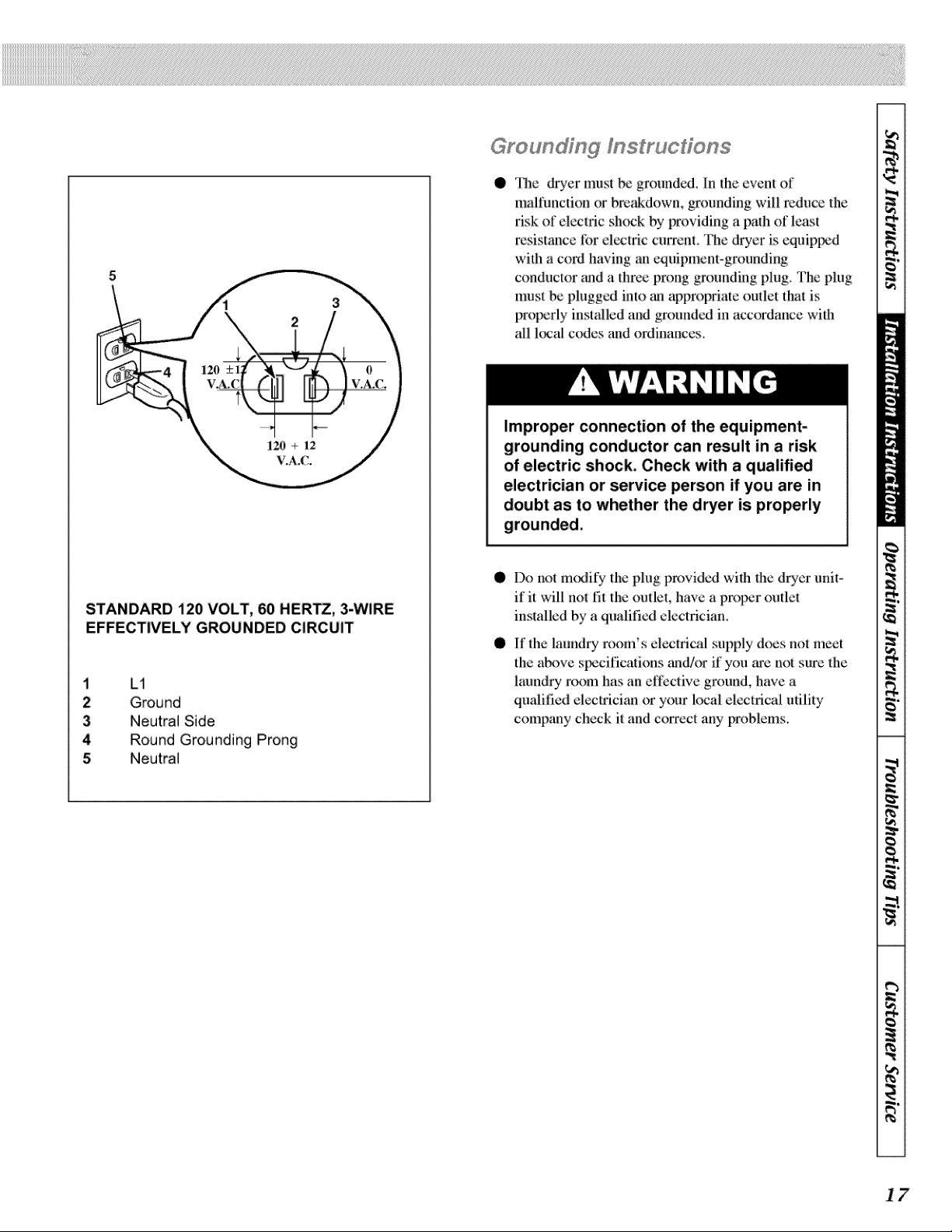
12(} + 12
V.A.{;.
STANDARD i20 VOLT, 60 HER_, 3-WIRE
EFFECTIVELY GROUNDED CIRCUIT
1 L1
2 Ground
3 Neutral Side
4 Round Grounding Prong
5 Neutral
Gi_o U_ dYn_ ' _S_UOdO_S
@
'l]]e {hT'er must be grounded. In t:he event of
malfunction or N:cakdown, grounding will reduce the
:risk of electfc shock by providing a path of least
:resistance :for electric currcnL I]]e dryer is equipi_d
with a cord having an equipment-grounding
conductor and a thrce prong grounding plug. The plug
must be plugged into an appropriate outlet that is
properly installcd and gronnded in accordance with
all local e(ydes and ordinances.
Improper connection of the equipment-
grounding conductor can result in a risk
of electric shock, Check with a qualified
electrician or service person if you are in
doubt as to whether the dryer is properly
@
@
Do not m{uJil} ' the plug provided with file dryer unit-
if it will not fit the outlet, have a prop:_r o,udel
installed by a qualified electrician.
If the laundry room's electrical supply does nol mcet
the aNwe specifications and/or if you _'e not sure _he
l_mndry :r_:)m has an effective ground, have a
qualified elecirician or your local electlical utility
company check it and correct any problems.
17
[11[
gvOl
Ill
Gas Dryers
N{)TE : The gas s_rvice to a gas d_er must conform
with the l{_al codes and ordinances or, in the absence
of h_al codes and ordinances, with the latest edition
of the National Fuel Gas Code ANSI Z223.1!NFPA
54 or the CAN/CGA-B149, National Gas Ins_llation
C_e.
L.P (Liquefied Petroleum) Gas, 2,500 Bm/fl :_(93.1
MJ/m_), service musi _ st_pplied at 8M 3 irL water
cohnnn pressure.
NOTE : DO NOT connect the dryer tu L.P. Gas
Service without converting the gas valve.
LP. gas conversion:
- Conversion must _e made by a qualified technician.
See gas valve burner base for gas conversion kit part
nuul_&
NOTE : When connecting to a gas line, an cquipment
shutoff valve must be installed within 6 feet (1.8m) of
the dryer. An 1/8 in. N.P.T. pipe plug must
installt_'l as shown. Refer to Fig.1
Supply line requirements:
Provide a rigid gas supply line to the dryer I{matiorL
- An individual manual shutnff valve nmst be installed
within 1.8m (6 feet) of me drycr in accordance with _le
Natiorml l:uel Gas Code ANSI Z223.1".
When a rigid pit_e is used it should be 1/2 inch IPS.
When acccplable m lhe gas supplier and l(mal codes, 318o
inch approved tubing mW b_,_u,ved for leuglhs under 6.1
m (20 l_2e{).For lcugths over 6.hn (20 lee0, larger
tubing sh{mld b_ used. t}it'_e2jointcoinpom_ds resislani to
the action of L.P. gas must _ used.
To r_uce the risk of gas leaks, fire or
• The dryer must be connected to the
type of gas as shown on the nameplate
Iocat_ in the door recess.
• Use a new flexible stainless steel
connector.
• Use pipe joint compound insoluble in
L.P. (Liquefied Petroleum) Gas, or
Teflon tape, on all pipe threads.
• Purge air and sediment from gas supply
line before connecting it to the dryer.
Before tightening the connection, purge
remaining air from gas line to dryer
until odor of gas is detected. This step
is required to prevent a gas valve
contamination.
• Do not use an open flame to check for
gas leaks. Use a non-corrosive leak
detection fluid.
Any dis-assembly requiring the u_ of
tools must be performed by an
authorized qualified service _rson,
18
Exhaust System Mat÷rials
A clothes dryer produces combustible
lint.
To reduce the risk of fire or gas
accumulation, the dryer MUST be
exhausted to the outdoors.
This gas appliance contains or produ_s
a chemical or chemicals which can cause
death or serious illness and which are
known to the State of California to cause
cancer, birth defects, or other
reproductive harm. To reduce the risk
from fuel combustion, make sure this
appliance is installed, operated, and
maintained according to the instructions
in this manual.
To reduce the risk of fire and the
accumulation of combustion gases, DO
NOT exhaust dryer air into a window well,
gas vent, chimney or enclosed,
unventilated area, such as an attic, wall,
ceiling, crawl space under a building or
concealed space of a building.
To reduce the risk of fire, DO NOT use
plastic or thin foil ductiong to exhaust
Exhaust system materials arc not supplied wifll the dryer.
Exhaust duct must bc lbur inches (10.2 cm) in diameter
having no obstructions. Rigid metal duct is
recolnmended. Non-comb,_stible flexible metal duct is
_mceptable. l)o not usc plastic or flfin foil ducfing,
_cause it contributes R) ix)or drying t_erl;:_rmauceand
collects lint, which can lead to a fire hazard.
Never install :flexible duct in concealed spaces, such as a
wall _ ceiling.
DO N(YI"use sheei: mcml screws _mexhaust pit_: joints
or other filstening me,ms which extend into the:duct that
could catch lint and :reduce the efficiency of the exhaust
system. Secn:m all joints with duct tat_:.
Ex saust System
IMPORTANT : Keep exhaust duct as short as
p_,_sble.
NOTE : Be certain old ducts are cleaned before
installing your new dryer.
For _st drying rcsults, recommended maximum length
of exh_mst system is shown in 72tble t.
To prevent backdrafl when duer is not in ot_.aration,
outer end of exhaust pit_ must have a weafllcr h_×)d wifl!
hinged damt_=rs (obtain l{mally).
19
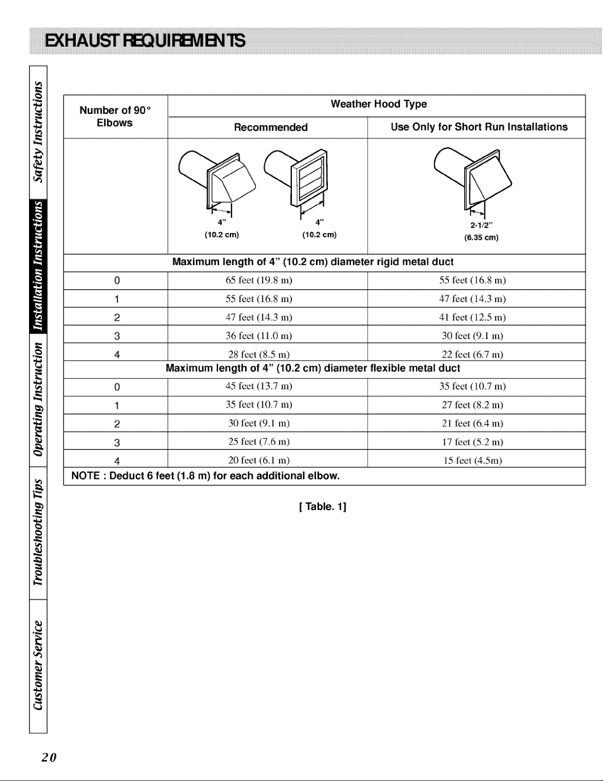
il
Number of 90 ° Weather Hood Type
Elbows Recommended Use Only for Short Run Installations
KL-£..
4" 4"
(10.2 cm) (i 0.2 cm)
2-1/2"
(6.35 cm)
Maximum length of 4" (i0.2 cm)diameter rigid metal duct
0 65 ftx_l:(19.8 m) 55 feet (16.8 m)
1 55 l_e| (16.8 m) 47 feet (14.3 m)
2 47 lee| (14.3 m) 41 feet (12.5 m)
3 36 fee_ (i i .0 In) 30 feet (9.1 m)
4 28 feet (K5 m) 22 t_et (6.7 m)
Maximum length of 4" (10.2 cm)diameter flexible metal duct
0 45 l_e| (13.7 m) 35 feet (10.7 m)
1 35 l_e| (10.7 m) 27 feet (8.2 m)
2 30 feet (9_1 m) 21 feet (6.4 m)
3 25 feet (7.6 m) 17 feet (5.2 m)
4 20 feet (6.1 m) 15 feet (4.5nl)
NOTE : Deduct 6 feet (i.8 m) for each additional elbow.
[ Table. 11
Exhsus_ System Msin_enanc÷
The dryer inte:rior and the complete exh_mst system
should _ inst_ctcd atier one year of use _mdcleaned if
necesvlry. Inst_ct _mdclean exhaust duct eve:u one m
two years as :required thercali:er.The weather h(×)d
should _ checked frequently to make sure the dampers
move :freely, they are not pushed in and that nothing lms
_en set _gainst them This maintenance work should be
done by"a qualified service persxm
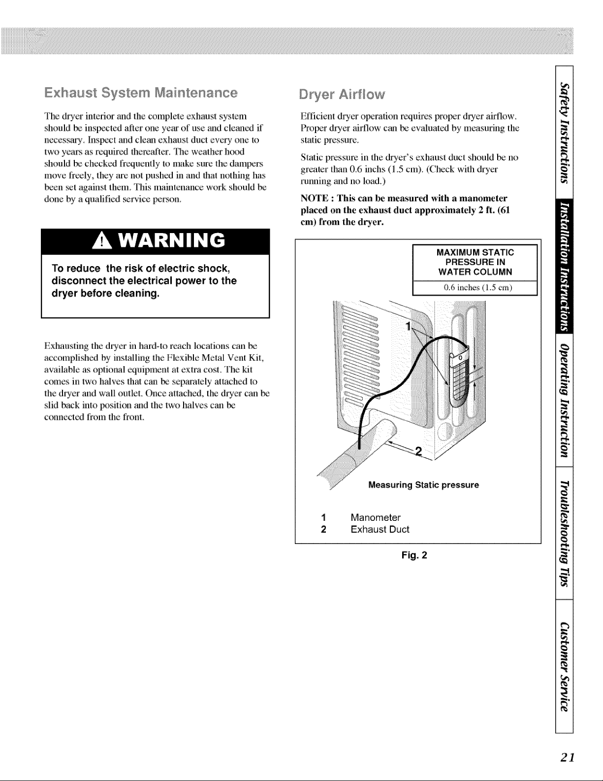
Dryer Airflow
Efficient dryer ope:ration requires prot_r dryer airtlow.
Proper d:ryer airflow can _ ew_luated by measuring tile
static pressure.
Static pressu:m in the &'yer's exhm_st &rot should _: no
greater them 0.6 inchs (I .5 cm). (Chc:ck with dryer
:running _md no load.)
NOTE : This can be measured with a manometer
placed on the exhaust duct appruxinmtely 2 ft. (61
cm) frum the dryer.
To reduce the risk of electric shock,
disconnect the electrical power to the
dryer before cleaning.
Exhausfirig the drycr in hard-to a=ach locations can be
accomplished by installing the Flexible Metal Vent Kit,
available as optional cquipment at extra cost. The kit
comes in two halves that can bc scp_u'ately attached to
the dryer and wall outlet. Once attached, the drycr can
slid back into position m_dthe two halves cm_be
conrmcted rrom the front.
1
2
MAXIMUM STATIC
PRESSURE IN
WATER COLUMN
0.6 inches (1.5 cm)
Measuring Static pressure
Manometer
Exhaust Duct
Fig. 2
21
Lubrication
All moving p_uls arc sealcd in a t_rma'lent supply of
lubricant or arc _uipped wilh oilless bearings.
Additional lu_icalion will not _ nccess_y.
Care of Your Dryer
Cle_m the lint :filler _:fore drying each load, The lint
filter may be washed if needed, Annually remove lhe lint
filter and allach Io the wlceuum dnet under it.
O:_inarily, the dryer cylinder will need no care,
Wipe the exlerior d_Ter cabinet as needed iffdetergent,
bleach or oilier washing p:r_ducts arc spilled on the
cabinet, wipe immediately. Some p:mducts will c_mse
l_rmanent damage if spilled on the cabineL
Use only a damp cMth lbr clemfing lhe conh'ol pancl.
Some spray prewash prc_ucls may h_uln ihc firfish on lhe
control panel.
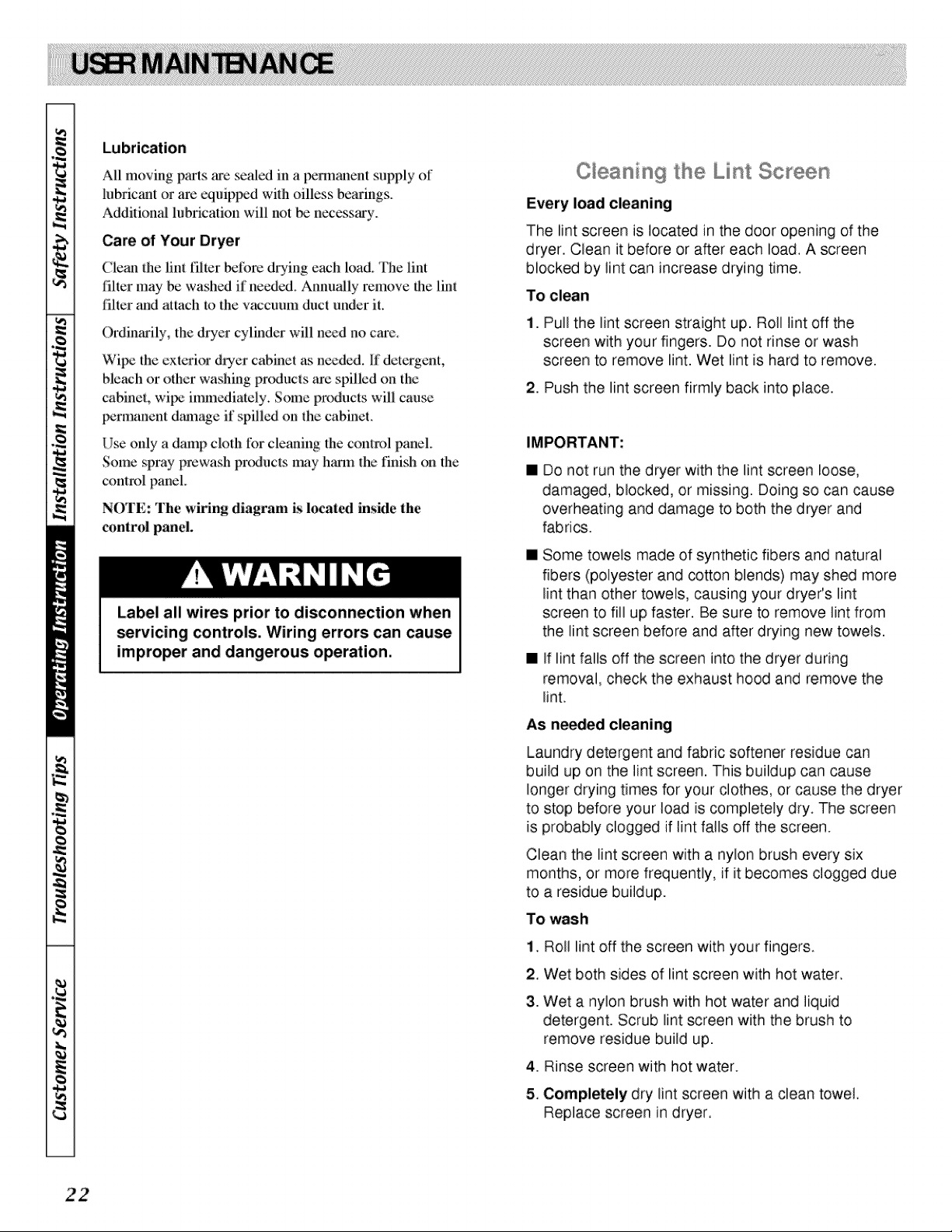
©ieaning lhe Lint Screen
Every load cleaning
The lint screen is located in the door opening of the
dryer. Clean it before or after each load. A screen
blocked by lint can increase drying time.
To clean
NOTE: The wiring diagram is local,,xi inside the
control panel.
i. Pull the lint screen straight up. Roll lint off the
screen with your fingers. Do not rinse or wash
screen to remove lint. Wet lint is hard to remove.
Label all wires prior to disconnection when
servicing controls. Wiring errors can cause
improper and dangerous operation.
2. Push the lint screen firmly back into place.
IMPORTANT:
[]
[]
Do not run the dryer with the lint screen ioose,
damaged, blocked, or missing. Doing so can cause
overheating and damage to both the dryer and
fabrics.
[]
Some towels made of synthetic fibers and natural
fibers (polyester and cotton blends) may shed more
lint than other towels, causing your dryer's lint
screen to fill up faster. Be sure to remove lint from
the lint screen before and after drying new towels.
If lint falls off the screen into the dryer during
removal, check the exhaust hood and remove the
lint,
As ne_ed cleaning
Laundry detergent and fabric softener residue can
build up on the lint screen. This buildup can cause
longer drying times for your clothes, or cause the dryer
to stop before your load is completely dry. The screen
is probably clogged if lint falls off the screen.
Clean the lint screen with a nylon brush every six
months, or more frequently, if it becomes clogged due
to a residue buildup.
To wash
1. Roll lint off the screen with your fingers.
2. Wet both sides of lint screen with hot water.
3.
Wet a nylon brush with hot water and liquid
detergent. Scrub lint screen with the brush to
remove residue build up.
4. Rinse screen with hot water.
5. Completely dry lint screen with a clean towel
Replace screen in dryer.
)....................
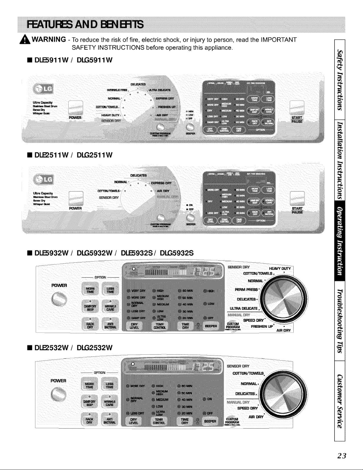
_WARNING - To reduce the risk of fire, electric shock, or injury to person, read the IMPORTANT
SAFETY INSTRUCTIONS before operating this appliance.
[] D_911W D_5911W
[] D_51 lW / D_251 lW
[] D_932W / D_5932W / D_932S/ D_5932S
[] DI..EZ532W / D_2532W
23
Explosion Hazard
Keep flammable materials and vapors,
such as gasoline, away from dryer.
Do not dry anything that has ever had
anything flammable on it (even after
Failure to follow these instructions can
result in death, explosion, or fire.
Fire Hazard
No washer can completely remove oil.
Do not dry anything that has ever had any
type of oil on it (including cooking oils).
Items containing foam, rubber, or plastic
must be dri_ on a clothesline or by using
an Air Cycle. Failure to follow these
instructions can result in death or fire.
The following is a guide to starting your dryer Please
refer to specific sections of this manual for more
detailed information.
1. Clean lint screen before or after each cycle.
2. Place laundry into dryer and shut door. See
"Loading."
3. Press the selected cycle pad The preset settings
for Sensor Dry' Cycles or Manual Cycles will glow,
The estimated or actual cycle time (in minutes) wili
show in the display.
24
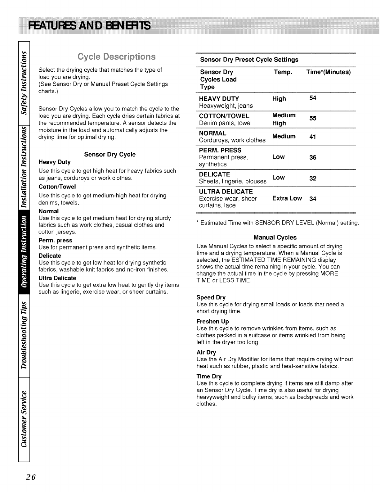
To use a 8ensoF ©Fy Oycb
I Select a Sensor Dry Cycle.
I Select DRY LEVEL to adjust how dry you want the
lead. As the cycle runs, the control senses the
dryness of the load and adjusts the time
automatically for the selected dryness level.
[] Sel_t the desired Options.
[] Press START/PAUSE
NOTE: DRY LEVEL selections can only be made
while using Sensor Dry Cycles. Selecting MORE Dry
or LESS Dry automatically adjusts the sensed time
needed.
O _Y DRY @ _E DRY
!, _E DRY
_DRY
0 DAMP_ @_
DLE_11W/G_11W
DLESg32W/G5932W
DLESg32&_G_
DLE_11W/G2511W
DLE_32W/G_2W
To use a Manua Dry Cycle
[] Select a Manual Dry Cycle.
[] Press MORE TIME or LESS TIME until the desired
drying time is displayed. Tap MORE TIME or LESS
TIME and the time will change by 1 minute intervals.
NOTE: The MORE TIME or LESS TIME feature can
be used with Manual Dry, Time Dry and Rack Dry
Cycles.
l MORE LEg
TIME TIME
[] Press TEMP. CONTROL until the desired
temperature indicator glows.
4. (OPTIONAL STEP) If desired, select OPTIONS. For
more details, see "Options."
5. Press START/PAUSE. Be sure the door is closed.
[] If you do not press START/PAUSE within 10
minutes of selecting the cycle, the dryer
automatically shuts off.
[] If you wish to end your drying cycle after pressing
START/PAUSE, press START/PAUSE again.
Stopping Your © yer
To stop your dryer at any time
Press START/PAUSE or open the door.
Pausing or Restarting
To pause the dryer at any time
Open the door or press START!PAUSE once.
To restart the dryer
Close the door. Press START/PAUSE.
NOTE: Drying will continue from where the cycle was
interrupted if you close the door and press START
within 10 minutes. If the cycle is interrupted for more
than 10 minutes, the dryer will shut off. Select new cycle
settings before resta_ling the dryer.
Child Lock
This feature allows you to lock },our settings to prevent
children from changing them. You can also use the child
lock feature to prevent unintended cycle or option
changes during dryer operation.
To enable the Child Lock feature:
Press and hold RACK DRY and ANTI BACTERIAL for 2
seconds. A single DEEP Tone is heard, and CL is
displayed. To unlock, press and hold RACK DRY and
ANTI BACTERIAL for 2 seconds. The indicator light
turns off
Properly loading your dryer can lower your utility bill and
prolong the life of your garments.
Loading suggestions
[] Load the dryer by the amount of space items take up,
not by their weight.
[] Do not overload the dryer. This causes uneven drying
and wrinkfing
Super Capacity Dryers
Heavy Work Clothes
4 jeans 2 sweatpants
4 workpants 2 sweatshirts
4 work shirts
CottonlTowels
10 bath towels 14 wash cloths
10 hand towels
Normal
3 sheets (1 king, 2 twin) 9 T-shirts
4 pillowcases 9 shorts
3 shirts 10 handkerchiefs
3 blouses
©yc e Descriptions
Select the drying cycle that matches the type of
load you are drying
(See Sensor Dry or Manual Preset Cycle Settings
charts.)
Sensor Dry Cycles allow you to match the cycle to the
load you are drying. Each cycle dries certain fabdcs at
the recommended temperature, A sensor detects the
moisture in the load and automatically adjusts the
drying time for optimal drying.
Sensor Dry Cycle
Heavy Duty
Use this cycle to get high heat for heavy fabrics such
as jeans, corduroys or work clothes.
Cotton/Towel
Use this cycle to get medium-Mgh heat for drying
denims, towels.
Normal
Use this cycle to get medium heat for drying sturdy
fabncs such as work clothes, casual clothes and
cotton jerseys.
Perm, press
Use for permanent press and synthetic items_
Delicate
Use this cycle to get low heat for drying synthetic
fabrics, washable knit fabrics and no-iron finishes.
Ultra Delicate
Use this cycle to get extra low heat to gently dry items
such as lingerie, exercise wear, or sheer curtains.
Sensor Dry Preset Cycle Settings
Sensor Dry
Cycles Load
HEAVY DUTY 54
Heavyweight, jeans
COTTON/TOWEL Medium 55
Denim pants, towel High
NORMAL Medium 41
Corduroys, work clothes
PERM. PRESS
Permanent press, Low 36
synthetics
DELICATE Low 32
Sheets, lingerie, blouses
ULTRA DELICATE
Exercise wear, sheer Extra Low 34
curtains, lace
* Estimated Time with SENSOR DRY LEVEL (Normal) setting
Manual Cycles
Use Manual Cycles to select a specific amount of drying
time and a drying temperature. When a Manual Cycle is
selected, the ESTIMATED TIME REMAINING display
shows the actual time remaining in your cycle. You can
change the actual time in the cycle by pressing MORE
TIME or LESS TIME.
Speed Dry
Use this cycle for drying small loads or loads that need a
short drying time.
Freshen Up
Use this cycle to remove wrinkles from items, such as
clothes packed in a suitcase or items wrinkled from being
left in the dryer too long.
Air Dry
Use the Air Dry Modifier for items that require drying without
heat such as rubber, plastic and heat-sensitive fabrics.
Time Dry
Use this cycle to complete drying if items are still damp after
an Sensor Dry Cyde, Time dry is also useful for drying
heawyweight and bulky items, such as bedspreads and work
clothe&
Manual Preset Cycle Settings
Manual Dry Default Time*
Cycles L_d
SPEED DRY Tu 25
SMALL LOADS
FRESHEN UP Medium 20
Remove Wdnkles
AIR DRY Air Dry 3,3
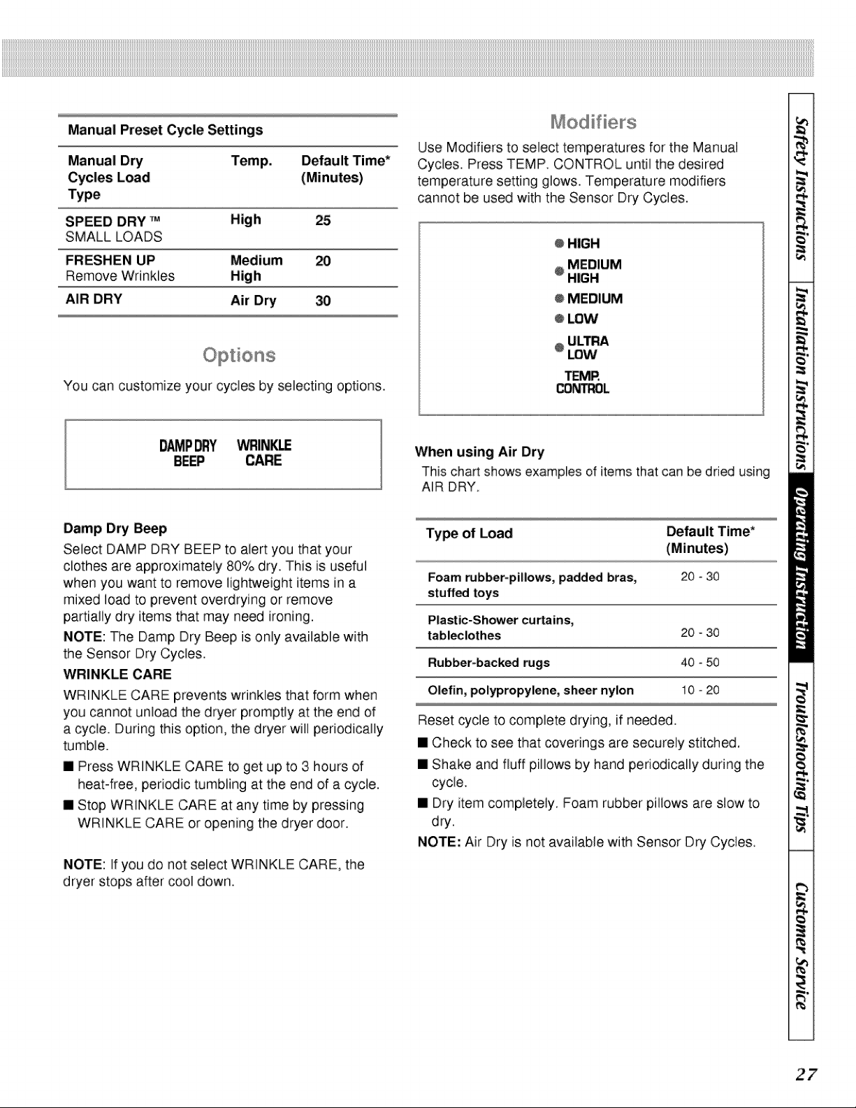
Use Modifiers to select temperatures for the Manual
Cycles. Press TEMP. CONTROL until the desired
temperature setting glows. Temperature modifiers
cannot be used with the Sensor Dry Cycles.
@HIGH
MEDIUM
@HIGH
@MEDIUM
o LOW
@ULTRA
LOW
TEMR
_t'TROL
You can customize your cycles by selecting options.
Vw_IN_
BEEP CARE
When using Air Dry
This chart shows examples of items that can be dried using
AIR DRY.
Damp Dry Beep
Select DAMP DRY BEEP to alert you that your
clothes are approximately 80% dry. This is useful
when you want to remove lightweight items in a
mixed load to prevent overdrying or remove
partially dry items that may need ironing.
NOTE: The Damp Dry Beep is only available with
the Sensor Dry Cycles.
WRINKLE CARE
WRINKLE CARE prevents wrinkles that form when
you cannot unload the dryer promptly at the end of
a cycle. During this option, the dryer will periodically
tumble.
[] Press WRINKLE CARE to get up to 3 hours of
heat-free, periodic tumbling at the end of a cycle.
[] Stop WRlNKLE CARE at any time by pressing
WRlNKLE CARE or opening the dryer door.
NOTE: If you do not select WRINKLE CARE, the
dryer stops after cool down.
Ty_ of Load Default Time*
Foam rubber-pillows, padded bras, 20 - 30
stuffed toys
Plastic-Shower curtains,
tabl_lothes 20 - 30
Rubber-backed rugs 40 - 50
Olefin, polypropylene, sheer nylon 10 - 20
Reset cycle to complete drying, if needed.
[] Check to see that coverings are securely stitched.
[] Shake and fluff pillows by hand periodically during the
cycle.
[] Dry item completely. Foam rubber pillows are slow to
dry.
NOTE: Air Dry is not avaiiable with Sensor Dry Cycles
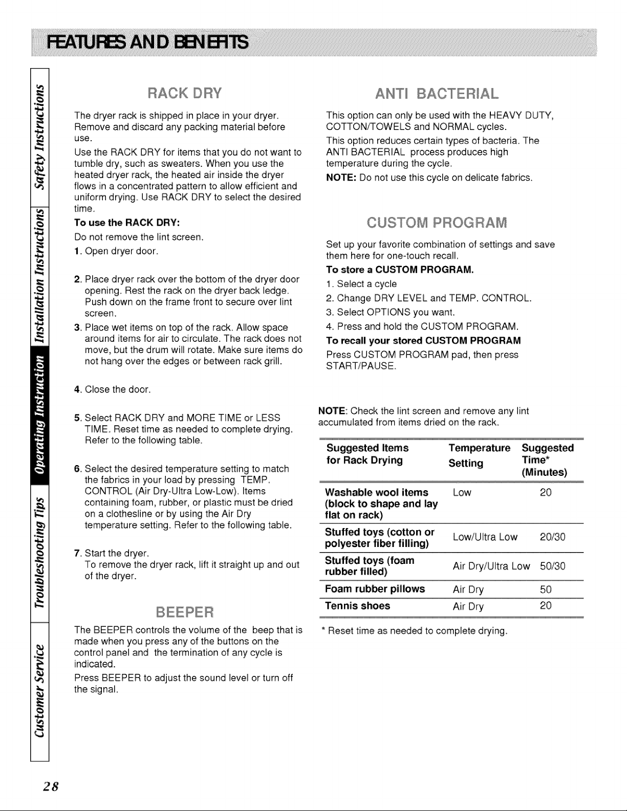
RACK © BY
The dryer rack is shipped in place in your dryer.
Remove and discard any packing material before
use.
Use the RACK DRY for items that you do not want to
tumble dry', such as sweaters. When you use the
heated dryer rack, the heated air inside the dryer
flows in a concentrated pattern to allow efficient and
uniform drying,. Use RACK DRY to select the desired
time,.
To use the RACK DRY:
Do not remove the lint screen,.
1. Open dryer door.
2 Place dryer rack over the bottom of the dryer door
opening Rest the rack on the dryer back ledge,
Push down on the frame front to secure over lint
screen,.
3,. Place wet items on top of the rack, Allow space
around items for air to circulate. The rack does not
move, but the drum will rotate. Make sure items do
not hang over the edges or between rack grill.
This option can only be used with the HEAVY DUTY,
COTTON/%OWELS and NORMAL cycles.
This option reduces certain types of bacteria, The
ANTI BACTERIAL process produces high
temperature during the cycle.
NOTE: Do not use this cycle on delicate fabrics_
CUSTOM PROGRAM
Set up your favorite combination of settings and save
them here for one4ouch recall,
To store a CUSTOM PROGRAM.
1. Select a cycle
2. Change DRY LEVEL and TEMP. CONTROL.
3. Select OPTIONS you want,
4. Press and hold the CUSTOM PROGRAM.
To recall your stored CUSTOM PROGRAM
Press CUSTOM PROGRAM pad, then press
START/PAUSE.
4_,Close the door.
5_,
6.
7.
Select RACK DRY and MORE TIME or LESS
TIME,. Reset time as needed to complete drying,
Refer to the following table.
Select the desired temperature setting to match
the fabrics in your load by pressing TEMP,
CONTROL (Air Dry-Ultra Low-Low), Items
containing foam, rubber, or plastic must be dried
on a clothesline or by using the Air Dry
temperature settings. Refer to the following table,
Start the dryer.
To remove the dryer rack, lift it straight up and out
of the dryer.
NOTE: Check the lint screen and remove any lint
accumulated from items dried on the rack
Suggest_ Items Temperature Suggested
for Rack Drying Time*
Washable wool items
(block to shape and lay
flat on rack)
Low 20
Stuffed toys (cotton or Low/Ultra Low 20/30
_lyester fi_r filling)
Stuffed toys (foam
rubber fill_) Air Dry/Ultra Low 50/30
Foam rub_r pillows Air Dry 50
Tennis shoes Air Dry 20
The BEEPER controls the volume of the beep that is
made when you press any of the buttons on the
control panel and the termination of any cycle is
indicated.
* Reset time as needed to complete drying
Press BEEPER to adjust the sound level or turn off
the signal.
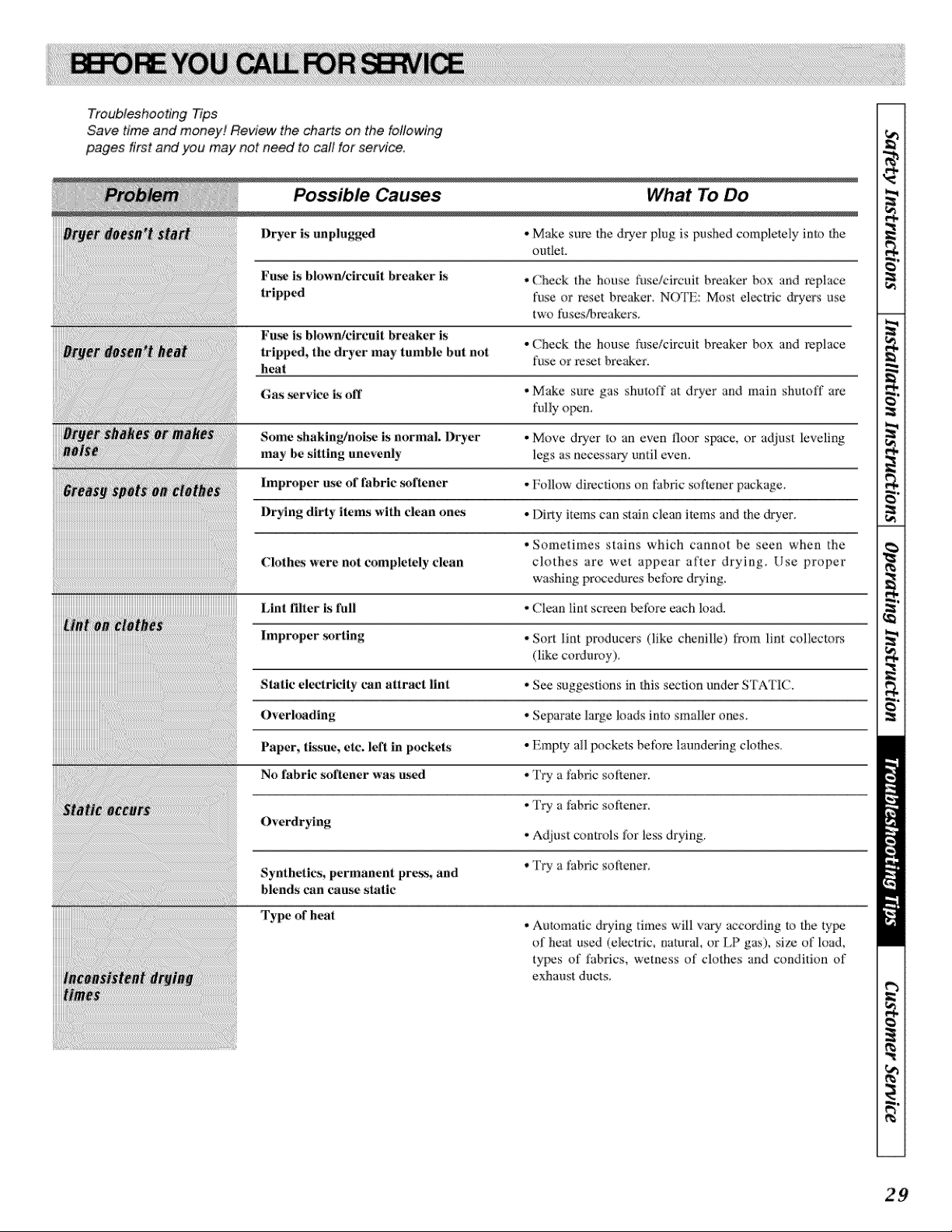
Troubleshooting Tips
Save time and money! Review the charts on the following
pages first and you may not need to call for service,
Possible Causes
Dryer is unplu_
Fuzz is blown/circuit breaker is
tripped
Fu_ is blown/circait breaker is
tripped, the dryer may tmnbie but not
l_eat
Gas _zrvice is off
Some shaking/noise is normal. Dryer
may be sitting unevenly
Improper _se of fabric _)fiener
Drying dirty items with clean on_
Clothes were not completely clean
Lint filter is full
Improper _)rting
Static electricity can attract lint
Overloading
Paper, tissue, etc. left in pockets
No fabric softener was a_d
Overdrying
Synthetics_ permanent prt_s_ and
blends can c.aa_ static
Type of heat
What To Do
• Make sure _he dryer plug is pushed completely Jmo the
outlet.
• Check the house fuse/circuit breaker box and replace
fuse or reset brenner; NOTE: Most electric &yers use
two Nseffbmakcrs.
• Check the house fuse/circuit breaker box and _place
fuse or rc_t brcakcr.
• Make sure gas shutoff at dryer and main shutoff arc
fully OF_m
• Move @er m an even floor space, or adjust leveling
legs as necessary until even,
• Follow directions on fabric sofmner package.
• Dirty items can stNn clem_ items and the dryer,
• Sometimes stains which cannot be seen when the
clothes are wet appear after drying. Use proper
washing pr_:edurcs bel;_re drying.
• Clean lint screen tx:fore each load.
• Sort lint producers (like chenille) from lint collectors
(like corduroy).
• See suggestions in _his section under STATIC.
• Separate large loads into smaller ones.
• Empty N1pockets beti)re laundering clothes_
• Try a :Nbric sotiene:r,
• Fry a Nbric softener.
• A{[iust controls lbr less drying.
• Try a fabric sotiener,
• Automatic drying times will v_) according to [he ty[x_
of heat used (electric, _mtural, or LP gas), sJzc of ioad,
types of fabrics, wetness of clothes and condition of
exhaust ducts_
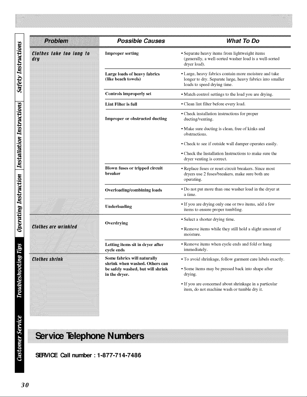
Possib_ Causes What To Do
Improper _>rting
iiiiiiiiiiiiiiiiiiiiiiiiiiiiiiiiiiiiiiiiiiiiiiiiiiiiiiiiiiiiiiiiiiiiiiiiiiiiiiiiiiiiiiiiiiiiiiiiiiiiiiiiiiiiiiiiiiiiiiiiiiiiiiiiiiiiiiiiiiiiiiiiiiiiiiiiiiiiiiiiiiiiiiiiiiiiiiiiiiiiiiiiiiiiiiLargehmdsofheavyfabrics
iiiiiiiiii Olkebeachtoweis
iiiiiiiiii
iiiiiiiiiiiiiiiiiiiiiiiii
iiiiiiiiiiiiiiiiiiiiiiiiiiiiiiiiiiiiiiiiiiiiiiiiiiiiiiiiiiiiiiiiiiiiiiiiiiiiiiiiiiiiiiiiiiiiiiiiiiiiiiiiiiiiiiiiiiiiiiiiiiiiiiiiiiiiiiiiiiiiiiiiiiiiiiiiiiiiiiiiiiiiiiiiiiiiiiiiiiiiiiiiiiiiiiLintFilterisfoll
iiiiiiiiiiiiiiiiiiiiiiiiiiiiiiiiiiiiiiiiiiiiiiiiiiiiiiiiiiiiiiiiiiiiiiiiiiiiiiiiiiiiiiiiiiiiiiiiiiiiiiiiiiiiiiiiiiiiiiiiiiiiiiiiiiiiiiiiiiiiiiiiiiiiiiiiiiiiiiiiiiiiiiiiiiiiiiiiiiiiiiiiiiiiii
iiiiiiiiiiiiiiiiiiiiiiiiiiiiiiiiiiiiiiiiiiiiiiiiiiiiiiiiiiiiiiiiiiiiiiiiiiiiiiiiiiiiiiiiiiiiiiiiiiiiiiiiiiiiiiiiiiiiiiiiiiiiiiiiiiiiiiiiiiiiiiiiiiiiiiiiiiiiiiiiiiiiiiiiiiiiiiiiiiiiiiiiiiiiii
iiiiiiiiii Improperorobs,r°, ', . d°ctl.
iiiiiiiiii
iiiiiiiiii
iiiiiiiiii
iiiiiiiiii
iiiiiiiiii
iiiiiiiiiiiiiiiiiiiiiiiiiiiiiiiiiiiiiiiiiiiiiiiiiiiiiiiiiiiiiiiiiiiiiiiiiiiiiiiiiiiiiiiiiiiiiiiiiiiiiiiiiiiiiiiiiiiiiiiiiiiiiiiiiiiiiiiiiiiiiiiiiiiiiiiiiiiiiiiiiiiiiiiiiiiiiiiiiiiiiiiiiiiiii
iiiiiiiiiiiiiiiiiiiiiiiiiiiiiiiiiiiiiiiiiiiiiiiiiiiiiiiiiiiiiiiiiiiiiiiiiiiiiiiiiiiiiiiiiiiiiiiiiiiiiiiiiiiiiiiiiiiiiiiiiiiiiiiiiiiiiiiiiiiiiiiiiiiiiiiiiiiiiiiiiiiiiiiiiiiiiiiiiiiiiiiiiiiiiiBlownfusesortrippedcircuit
iiiiiiiiiiiiiiiiiiiiiiiiiiiiiiiiiiiiiiiiiiiiiiiiiiiiiiiiiiiiiiiiiiiiiiiiiiiiiiiiiiiiiiiiiiiiiiiiiiiiiiiiiiiiiiiiiiiiiiiiiiiiiiiiiiiiiiiiiiiiiiiiiiiiiiiiiiiiiiiiiiiiiiiiiiiiiiiiiiiiiiiiiiiiiibreaker
iiiiiiiiiiiiiiiiiiiiiiiiiiiiiiiiiiiiiiiiiiiiiiiiiiiiiiiiiiiiiiiiiiiiiiiiiiiiiiiiiiiiiiiiiiiiiiiiiiiiiiiiiiiiiiiiiiiiiiiiiiiiiiiiiiiiiiiiiiiiiiiiiiiiiiiiiiiiiiiiiiiiiiiiiiiiiiiiiiiiiiiiiiiiii
iiiiiiiiiiiiiiiiiiiiiiiiiiiiiiiiiiiiiiiiiiiiiiiiiiiiiiiiiiiiiiiiiiiiiiiiiiiiiiiiiiiiiiiiiiiiiiiiiiiiiiiiiiiiiiiiiiiiiiiiiiiiiiiiiiiiiiiiiiiiiiiiiiiiiiiiiiiiiiiiiiiiiiiiiiiiiiiiiiiiiiiiiiiiii
iiiiiiiiiiiiiiiiiiiiiiiii
. Separate heavy items fixm_lightweight items
(generally_ a well-sm_ed washer load is a weii-sorted
dryer load).
. Large, heavy fabrics contain more moisture and t_e
longer to dry_ Separate large, heavy t_b:rics into smaller
loads to speed drying time.
• Match control settings to the load you are drying,
• Clean lint :filer bet:ore every load.
. Check installation instructions fiar proper
ducting/venting_
• Make sure ducting is clean, free of kinks and
obstructions.
, Check _o s_ if outside wall damper oD:rates easily.
• Check _he Installation Instrnctions to make su:_ the
dryer venting is correct.
. Rcplace fuses or re_t circuit breakers. Since most
dryers use 2 tuses!-breakers, make snre l_th are
operating.
• Do not put more thm_one washer load in the dryer at
a time_
Underloading . If you are drying only one or two items, add a few
items to ensnre proper rambling.
Overdrying
. Selec_ a shorter drying time.
, Remove items while they still hold a slight amom_t of
moisture.
Letting items sit in dryer after
cycle ends
* Remove items when cycle ends and fold or hang
immediately_
Some fabrics will naturally
hrink when washed. Others can
be safely washed, but will shrink
in the dryer.
• To avoid shrinkage, follow garment care labels exactly.
° Some items may be pressed back into shaF_ after
drying.
• If you are concerned about shrinkage in a p:micular
item, do not machine wash or tumble dry-it.
_1_ Call num_ • 1-877-714-7486
3O
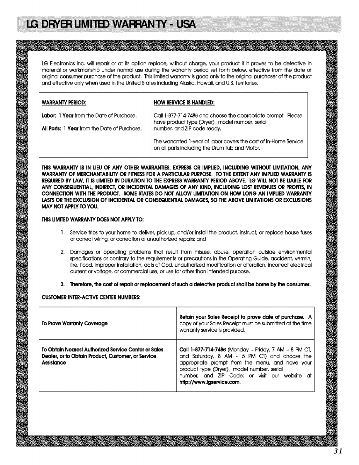
LG Electronics Inc, will repair or at its option replace, _th, ourf charge, your product if it proves to be defective in
material or workmanship under normal _ during the warranty period set forth below, effective from the date of
original consu_ purch_ of the product, Thislimited warranty is g_ only to the ori@na[ purchaser of the product
and effective only when u_ in the United States including Ai_a, Hawaii, and U,S,Te_torles,
W_ _N3X PER_D:
La_: 1 Year from the Date of Purchase,
All Parts: 1Year from the Date of Purch_ase,
HOW_RVICE B _ND_D:
Call 1-877-714-7486 and choose fl_e approp_ate prompt, Ple_
have product ty_ (Dryer), model number, serial
number, and ZiPcode reac_y.
The warranted !_-year of laber cove_ the cost of In-Home Service
on all parts [_[uding the Drum Tub and Motor,
THBWA_ iS IN UEUOF ANY OTHERWA_NTIES, D(PR_ OR IMPLIED,INCLUD|NG_HOLIT LIMffATION,ANY
WARRANTYOF M_::HANTABIL_ ORFITN_ FORA PART_U_ PURPOSE.TOTHE_NT ANYIMPUEDWA_NT'_ IS
_JIRED BYLAW,iT ISLIMED IN DURAT_NTOTHEEXPRF.SSWARRANTYPE_.ODABOVE. LGWILLNOTBEUAB_ F_
ANY_ENTIAL INDI_CT, _ INCIDENTALDAMAGESOF ANYKIND,INCLUDINGLCSTREVENUES_ PROFITS,|N
_NNECTION WITHTHE_D_. _E STA_ _ NOTALLOWLIMITATION_ HOW LONGAN IM_JEDWARRANTY
LASTSORTHEEXCLUSIONOFINCIDENTALOR_ENTIAL DAMAGES,_ THEABOVELIMITATIONSOR EXCLUSIONS
MAY NOTAPPLYTOY_J.
THiSUM_D W_r, ANiY D_S NOTAPPLYTO:.
!, SeMce trips to your home to deliver, pick up, and/or Install _ product, instruct, or replace house fu_
or correct wiring, or correct.on of unaLffhoflzed repairs; and
Damages or o_rating problems that result from misuse, abuse, o_ration OL:fl_ide environmental
_cmcatlom or contrary to the requirements or precautions in the Operating Guide, accident, vermin,
tire, flood, impro_r Ir'_allation, acts of God, unauthorized rr_lflcatton or alteration, incorrect electrical
current or volta_, or com_cia[ use, or _ for other than intended purpose,
3. Therefore,the _ of repofr_ _ce_. t of sucha _ecllve product_all be borne by lhe _sun'_er.
OJST_ER |_R-ACTIVE CENTERNUMBE_:
ToProveWarrantyCove_
To_In NearestAL_,orlzed_n,'Ice Cente__
Dea_, or to ObtainP_uct, Cu_e_, or _rvice
Ass_e
_In yourSalesReceipttoprovedateofpurchase.A
copy of your _]esReceipt mustbe submifled at the time
warranty service is provided.
_11 1-877-714-7486 (Monday - Friday, 7 N_ ~ 8 _ CT;
and Saturday, 8 AM ~ 5 PM CT) and choose the
appropriate prompt from the menu, and have your
p_duct tybe (Drye0, model number, serial
number, and _P Code; or visit our website at
_://ww'wJgse_lce.com,
3]

P/No.: _28EL4001A
