
Instullution end Operuting Guide
Model Numbers I P60W38, P60W38H I PLASMA DISPLAY PANEL
]
£ [bpyF ght 2@[}3, ZeI@h E ect (_Hzs C_ tp _,_@t_m
zenith
Warning
s
rn In
WARNING
WARNING"
TO REDUCE THE RISK OF ELECTRIC SHOCK DO NOT REMOVE COVER (OR BACK) NO USER
SERVICEABLE PARTS _NSIDE. REFER TO QUALIFIED SERVICE PERSONNEL.
The lightning flash with arrowhead symbol, within an equilateral triangle is intended to alert the user to
the presence of uninsu_ated dangerous voltage" w_bin tile product's enclosure that may be of suffi-
cient magn_ude to const_ate a risk of et_ric shock to persons.
The exclamation poinl within an equi_atera{ tfi_gle is intended to alert the user to the presence of
important operating and maintenance (servicing) instructions in the literature eccomp_ying the appli-
ance
WARNING
TO PREVENT FiRE OR SHOCK HAZARDS, DO NOT EXPOSE THIS PRODUCT TO RAIN OR MOISTURE.
FCC NOTICE
• A Class B digital device
This equipment has been tested and found to comply with the iimits for a Class B digital device, pursuant to Part
15 of the FCC Ru_es. These limits are designed to provide reasonable protect:ion against harmful interference in
a residential installation. This equipme_ generates, uses and can radiate radio frequency energy and, if not
inc4alled and used in accordance with the instructions, may cause harmfu_ interference to radio communications.
However, tllere is no guarantee that interference will not occur in a particular installation, if this equipment does
cause harmful interference to radio or television reception, whid-_ can be determin_ by turning the equipment off
and on the user is encouraged to try to correct the interference by one or more of the following measures:
- Reorient or relocate the receiving antenna
- _ncrease the separation between the equipment and receiver.
- Conned the equipment into an outlet on a circuit different from that to which the receiver is connected.
- Consult the dealer or an experienced radio/TV technician for help
• Any changes or modifications not expressly approved by the party responsible for compli-
ance could void the user's authority to operate the equipment.
CAUTION:
Do not attempt to modify tills product in any way w_hout written m,_horiz_ion from Zenith Electronics
Corporation, Unauthorized modification could void the user's aut:hor_y to operate this product
COMPLIANCE:
The responsible party for this product's compliance is:
Zenith Electronics Corporation
2000 MiHbrook Drive
Lincolnshire, II 60069 USA
Phone: 1-_7-941 8_0
WARNING
TO REDUCE THE RISK OF FIRE AND ELECTRIC SHOCK, DO NOT EXPOSE THIS PRODUCT TO
RAIN OR MOISTURE
2 Pl_ma Display
SafetyInstructions
F
important safeguards for you and your new product
"four product has been manufactured and tested with your safety in mind However, improper use can result in potential eiec _
trical shock or fire hazards, To avoid defeating the safeguards that have been built into your new product please read and
observe the following safety points when instaJling and using your new product, and save them for future reference
Observing time simple precautions discussed in this manual can help, you get the many years of enjoyment and safe opera-
tien that are built into your new product.
This product complies with all applicable U.S, Federal safety requirements, and those of the Canadian Standards Association.
1, Read Instructions
All the safety and operating instructions should be read
before the product is operated
2. Follow Instructions
All operating and use instructions should be foimowed,
3, Retain instructions
The safety and operating instructions should be retained for
future reference.
4, Heed Warnings
A_I warnings on the product and in the operating instructions
should be adhered to.
5, Cleaning
UnpEug this product from the wall outlet before denning. Do
not use liquid c_eaners or aerosol c_eaners Use a _mp
cloth for denning.
& Water and Moisture
Do not use this preduct near water, for exampte, near a bath
tub wash bowf kitchen sink or laundry tub in a wet base-
merit or near a swimming poet.
7, Accessories, Carts, and Stands
Do not place this preduct on a slippery or fitted surface, or on
an unstable cad, stand, tripod, bracket, or table. Tl_e product
may slide or fuji, causing ser_oas injury to a child or aduff,
and serious damage to the product Use only with a cart,
stud triped, bracket or table recommended by the manu
facturer, or sold with the product. Any mounting of the prod-
uct should fotlow time manufacturer's instructions, and should
use a mounting accessory recommended by the manufac-
turer.
8, Trans_rting Product
A product and cart combination should be moved with care.
Quick stops, excessive force, and uneven surfaces may
cause the product and cart cembin_ion to overturn.
9. Attachments
Do not use attachments not recommended by the product
manufacturer as they may cause hazards.
10, Ventilation
Slots and openings in the cabinet are provi_d for ventilation
and to ensure reliable operation of the product and to protect
it from overheating, and these openings must not be blocked
or covered The openings should never be blocked by plac-
ing the product on a bed, sofa, rug, or other similar surface.
_is product sboutd not be placed in a buiitoin installation
suclm as a bookcase or rack unless proper ventimation is pro-
vided or the manufacturer's instructions have been adl_ered
to_
11. Power Sources
This product should be operated only from the type of power
source indicated on the marking I_el. If you are not sure of
the type of power supply to your home consult your product
dealer or _ocal power company. For products i_ended to
operate from b_ery power, or other sources, refer to the
operating instructions
12. Power-Cord Polarization
This product is equipped with a three-wire grounding type
plug, a plug having a third (grounding) pin. This plug will onty
fit into the grounding-type power outlet. This is a safety fea-
ture. If you are unable to insert the plug into the outlet, con-
tact your electrici_ to replace your obsolete outlet Do not
defeat the safety purpese of time grounding4ype p_ug.
13. Power-Cord Protection
Power-supply cords should be routed so that they are not
likely to be walked on or pinched by items placed upon or
against tbem_ paying particular attention to cords at plugs
convenience receptacles, and the point: where they exit from
the product
POR_,'kBL E CART WARN iN G
Owner*s Manua/ 3
Safety Instructions
Instructio ns co nt inued
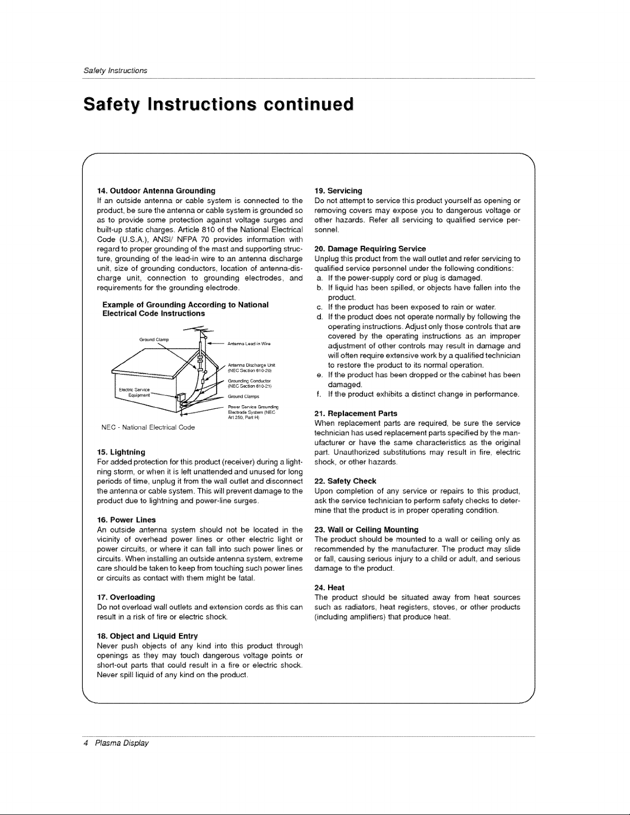
14. Outdoor Antenna Grounding
if an outside antenna or cable system is connected to the
product, be sure the antenna or cable system is grounded so
as to provide some protection against voltage surges and
built-up static charges. Adic[e 810 of the Nationa_ Electrical
Code (U.S.A.), ANSI/ NFPA 70 provides information with
regard to proper grounding of the mast and supporting struc-
ture, grounding of the _ead-in wire to an antenna discharge
unit size of grounding conductors, _ocation of antenna-dis-
charge unit connection to grounding electrodes, and
requirements for the grounding electrode.
Example of Grounding According to National
Electrical Code Instructions
Gr_'_r_J C_mp
G_ur_ ¢_mp_
P_er Oe_e _eundi_
Art 2_e P_ H)
NEC - Nat onat E_ectrica_Code
15. Lightning
For added protection for this product (receive0 during a light-
ning storm, or when it is left unattended and unused for long
periods of time, unpfug it from the wall outlet and di_onnect
the antenna or cable system. This wilt prevent damage to the
product due to lightning and power-line surges.
16, Power Lin_
An outside antenna system sl_ould not be located in the
vicinity of oved_ead power lines or other electric light or
power circuits, or where it can faJ_ into such power lines or
circuits, When installing an outside antenna system, extreme
care should be taken to keep from touching such power lines
or circuits as contact with them might be fatal,
17. Overloading
Do not overload wall outiets and extension cords as this can
result in a risk of fire or el_fic shock.
18. Object and Liquid Entry
Never push objects of any kind into this product through
openings as they may touch dangerous voltage points or
short-out parts that could result in a fire or electric shock
Never spill liquid of any kind on the product.
19, _rvicing
Do not attempt to service this product yourseff as opening or
removing covers may expose you to dangerous voltage or
other hazards. Refer aH servicing to qualified service per °
sonneL
20, Damage Requiring Service
Unplug this product from the wal_ outlet and refer servicing to
qualified service pe_onne_ under the fo_owing conditions:
a, tf the power°supply cord or plug is damaged,
b. tf liquid has been spi_ied, or objects have fallen into the
product,
c ifthe product has been exposed to rainor ware[,
d_ tf the product does not operate normally by following the
operating instructions. Adjust only those controls that are
covered by the operating instructions as an improper
adjustment of other controls may result in damage and
wi_[ often require extensive work by a qualified technician
to restore the product to its norma_ o_ration.
e, if the product has been droppod or the cabinet has been
damaged.
f. If the product exhibits a distinct change in performance
21, Repl_ement Parts
When replacement parts are required, be sure the _rvice
technician has us_ replacement parts specified by the man°
utacturer or have the same characteristics as the original
part. Unauthorized substitutions may result in fire, electric
shock, or other hazards,
22, Safety Check
Upon completion of any _wice or repairs to this product,
ask the service technician to perform safety checks to deter-
mine that the product is in proper operating condition
23. Wall or Ceiling Mounting
The product shouid be mounted to a wa]_ or ceiling only as
recommended by the manufacturer. The product may slide
or fall, causing sedous iniury to a cl_ild or adu_, and serious
damage to the product.
24. Heat
The product should be situa4ed away from heat sources
such as radiators heat registers,, stoves,, or other products
(including amplifiers) that produce heat.
4 Plasma Display
Conten_s
Warnings ...................................... 2
Safety Instructions ............................ 3.°4
introduction
Controls _d Connection Options ........... 7
Remote Control Key Functions ............... 8
Installation
InstallationInstructions.................. 9_I0
Externa_ Equipment Connections .......... 11 --14
VCR Setup ....................... 11
Cabte TV Setup ........................ 11
External/VV Source Setup .................. 12
DVD Setup ............................... 12
DTV Setup ........................ 12
PC Setup ............................ 13-_14
Operation
Turning on time Monitor ................. 15
Menu Language Selection ................... 15
Video Menu Options
APC (Auto Picture Control) .......... 16
Manual Picture Control ............... 16
Aulo Color Temperature Controt .......... 16
Manual Color Temperature Control .......... 16
Audio Menu Options
DASP (Digital Auto Sound Processing) ...... 17
Manual Sound Control .............. 17
AVL (Auto Volume Leveler) ................ 17
Time Menu Options
Clock setup ........................... 18
On/Off Timer Setup ..................... 18
Auto Off ............................. 18
Sleep Timer ........................... 18
Special Menu Options
Key Lock ................................ 19
ISM Method ............................ 19
Low power ............................ 19
Menu Rotation For Vertica_ Viewing ............ 19
Screen Menu Options
Auto Adjustment ........................ 20
Setting Picture Format ................. 20
Picture Size Zoom ...................... 20
SpI_ Zoom .............................. 21
_reen Position ........................ 21
Manual Configure .............. 21
_reen Adjustmems ........................ 22
Initializing.............................. 22
Selecting Wide VGA/XGA mode ............. 22
Luminance Noise Reduction .............. 22
PIP (Picture-in-Picture)Fe_ure
Watching PIP ............................. 23
PIP Size ................................. 23
PIP Aspect Ratio ....................... 23
Swapping PIP ........................... 23
Moving PIP ............................. 23
selecting an input Signa_ Source for P_P ...... 23
Twin Picture Setup Options
Watching Twin Picture .............. 24
Sub Picture Size Adjustment ............... 24
Swapping the Twin Picture ................. 24
Selecting a Source for the Twin Picture ....... 24
External Control Device Setup ................ 25_30
IR Code Information ...................... 31o-32
Troubleshooting Checklist ...................... 33
Maintenance ................................. 34
Specifications .................................. 34
Your' Zenith Limited Warranty ................... 35~36
Setup and Operation Checklist
Setup and Operation Ch_klist
(See pages 11~13 for available connection and operational setup options)
1. Unpack Monitor and aH acc_s_ries,
2. Connect all external video and audio equipment,
see pages 11 '_13
3 install b_eries in remote control
See page 8,
4 Turn Monitor on.
See page 15
5. Turn video source equipment on.
6. Select viewing source for Monitor.
see page 8.
7. Fine-tune source image and _und to personal preference
or as required by source,
See pages 16 _ 17.
8. Additional features Setup
see Contents above.
After reading this manual keep it handy for future reference,
Owner's Manual 5
Introduction
What is a Plasma Display Panel (PDP)?
If voltage is applied to gas w_thinglass panels ultraviolet rays are produced and fused with a fluorescent substance At that
instant, _ightis emitted A P{asma Display is a next generation fiat Display using this phenomenon.
160 ° - Wide angle range of vision
Your featpane_ plasma screen offers an exceptionally broad viewing angle _- over 160 degrees, This means that the display is
clear and visible to viewers who can see the screen anywhere in the room
Wide Screen
The screen of tl_e Plasma DispUayis 60" so wide that your viewing experience is as if you are in a theater_
Multimedia
Connect your plasma display to a PC and you can use it for conferencing games, and intemet browsing The Pictureqn-Picture
feature atlows you to view your PC and video images simultaneously.
Versatile
The tighl weight and thin size makes it easy to instaliyour ptasma display in a variety of tocations where conventiona_ TVs woutd
notfit
The PDP Manufacturing Process: Why minute colored dots may be present on the PDP screen
The PDP (Piasma Display Panel) which is the display device of this product is composed of 0.9 to 2,2 million ceils. A few cell
defects will normatly occur in the PDP manufacturing process, Severa_ minute colored dots visible on the screen shouid be accept-
able. This also occurs in other PDP manufacturers' products and the tiny dots appearing does not mean that this PDP is defective.
Thus a few ceil defects are not sufficient cause for the PDP to be exchanged or returned Our production technogogy is designed
to minimize cett defects dunng the manufacture and operation of this product
Cooling Fan Noise
In the same way that a fan is used in a PC computer to keep the CPU (Central Processing Unit) cool the PDP is equipped w_h
cooling fans to cool the Monitor and improve its reHabil_y. Therefore, a certain leve_ of noise could occur wNe the fans are operat-
ing and cooming the PDP.
The fan noise _esn3 have any negative effect on the PDP's efficiency or reliability, The noise from these fans is normal dudng the
operation of this produ_, We hope you understand that a certain leve_ of noise from the cooling fans is acceptable and is not suffi-
cient cause for the PDP to be exchanged or returned.
6 Pl_ma Display
introduction
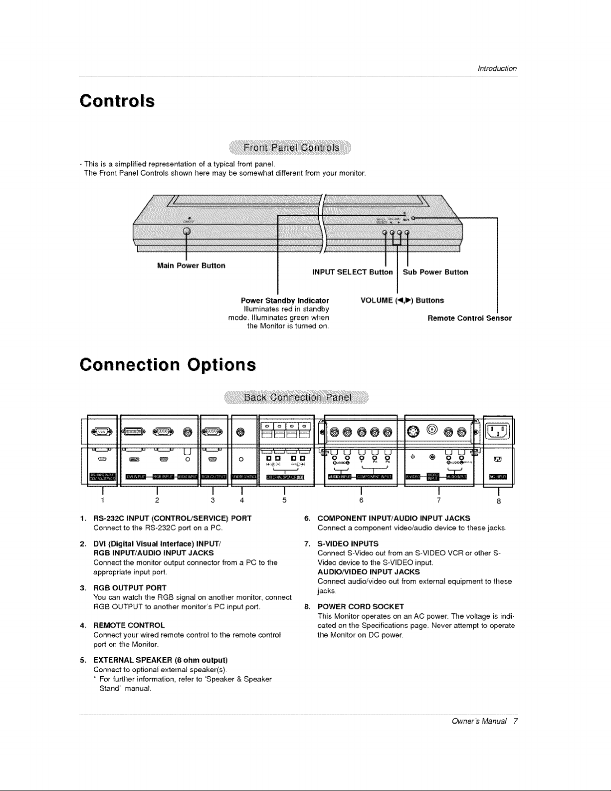
This is a simplified representation of a typica_ front pane_
The Front Pane_ Controls shown here may be somewhat different from your monitor_
Main Power Button
INPUT SELECT Button Sub Power Btrtton
Power Standby indicator
illuminates red in standby
mode [Huminates green when
the Monitor is turned on.
VOLUME (<1,1_) Buttons
Remote Control Sensor
Connection Options
oli,
@@@@
1¸
I I I
2 3 4
ma ae o o g £ £ I I @ &o r
I I I
5 6 7
ma[
2.
3_
4_
5,
RS-2320 INPUT (CONTROL/SERVICE) PORT
Connect to the RS-232C port on a PC_
DVI (Digital Visual interface) INPUT/
RGB INPUT/AUDIO INPUT JACKS
Connect the mon_or output connector from a PC to the
appropriate input port.
RGB OUTPUT PORT
You can watch the RG8 signat on another monitor, connect
RGB OUTPUT _o another monitor's PC input port,
REMOTE CONTROL
Connect: your wired remote control to the remote cor_rol
port on the Monitor,
EXTERNAL SPEAKER (8 ohm output)
Conn_ to optiona{ extema_ speaker(s),
* For further information, refer to 'Speaker & Speaker
Stand' manua_
6,
7.
8_
C_PONENT INPUT/AUDIO INPUT JACKS
Conned a component video/audio device to these j_ack&
S-VIDEO INPUTS
Connect S-Video out from an S VIDEO VCR or other S-
Video device to the S-ViDEO input,
AUOIO/VIDEO INPUT JACKS
Connect audio/video out from externat equipment to these
jacks,
POWER CORD SOCKET
This Monitor operates on an AC power The voyage is indi o
cat_ on the Specifications page Never attempt to operate
the Monitor on DC power.
Owner's Manual 7
Introduction
Remote Control Key Functions
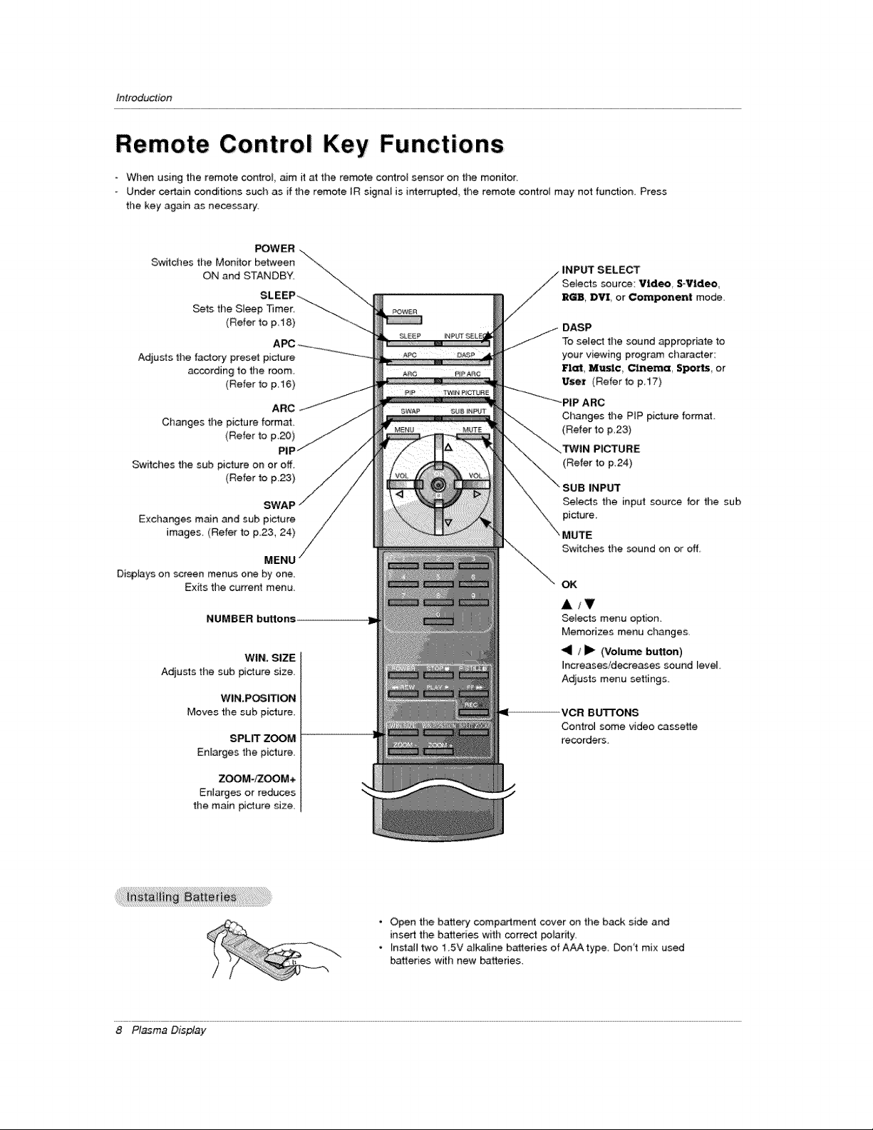
When using the remote corCtroL aim it at the remote control sensor on the monitor
Under certain conditions such as if the remote IR signal is interrupted, the remo_e controt may not function, Press
the key again as necessary
POWER ....
Switches the Monitor between "\
ON and STANDBY, "_..
SLEEP_-_ .... \-\
Sets the S_eep _mer _-_
(Refer to p 18) -_--.._
Adju_s the factory preset picture
according to the room.
(Refer to p 16)
ARC
Changes the picture format
(Refer to p.20)
PIF
Switches the stJb pi_ure on or off.
(Refer to p,23)
SWAP
Exchanges m_n and sub picture
images. (Refer to F23, 24)
MENU
Disp[ays on screen menus one by one.
Exits the current menu
/
NUMBER buttons
WIN, SIZE
Adjusts thesab picture size,
WIN.POSI_ON
Moves the sub picture.
SPLIT ZOOM
Enlarges the picture.
ZOOM-_OOM+
Enlarges or reduces
the main picture size.
DASP
To select the sound _propriate to
your viewing program character:
Flat, Music, Cinema, Spo-_, or
User (Refer to p17)
--'_'_....... _PIP ARC
Changes the PiP picture format
(Refer to p,23)
(Refer to p,24)
INP_
Selects the input source for the sub
picture.
MUTE
Switches the sound on or off.
OK
A/T
_te,cts menu option
Memorizes menu changes,
<1 / _1_ (Volu_ button)
increases/decreases sound level,
Adjusts menu settings
ICR B U'B'ONS
Control some video cassette
recorders.
• Open the battery compartment cover on the back side and
insert the batteries with correct poiarity.
• Instal_ two 1 5V alkaline batteries of AAA type Don't mix used
batteries with new batteries.
8 Pl_ma Display
tnstaltation
t
IOn
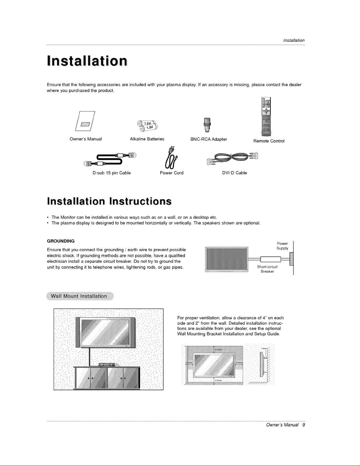
Ensure that the following accessories are inc[u_d with your plasma display If an accessory is m[ssing_ please contact the dealer
where you purchased the product,
Owners Manual A_kaline Bakeries BNC-RCA Adapter Remote Control
D_sub 15 pin Cable Power Cord DVFD Cable
* The Monitor can be installed in various ways such as on a wall, or on a desktop etc
- The plasma display is designed to be mourned horizo_l[y or verticam_y, The speakers shown are optional
GROUNDING
Ensure that you connect tl)e grounding / earth wire to prevent possiMe
e{ectric shock, If grounding methods are not possib{e, have a qualified
electrician insta_[ a serrate circuit breaker Do not try to ground the
unit by connecting it to telephone wires lightening rods or gas pipes
Power
Supply
Sho_l-circuit
Breaker
i:i i ii
For proper ventilation allow a clearance of 4' on each
side and 2_ from the wa& Detailed installation instruc
tions are available from your dealer, see the optional
Wail Mounting 8r,acket Installation and Setup Guide
Owner's Manual 9
Ins talla tie n
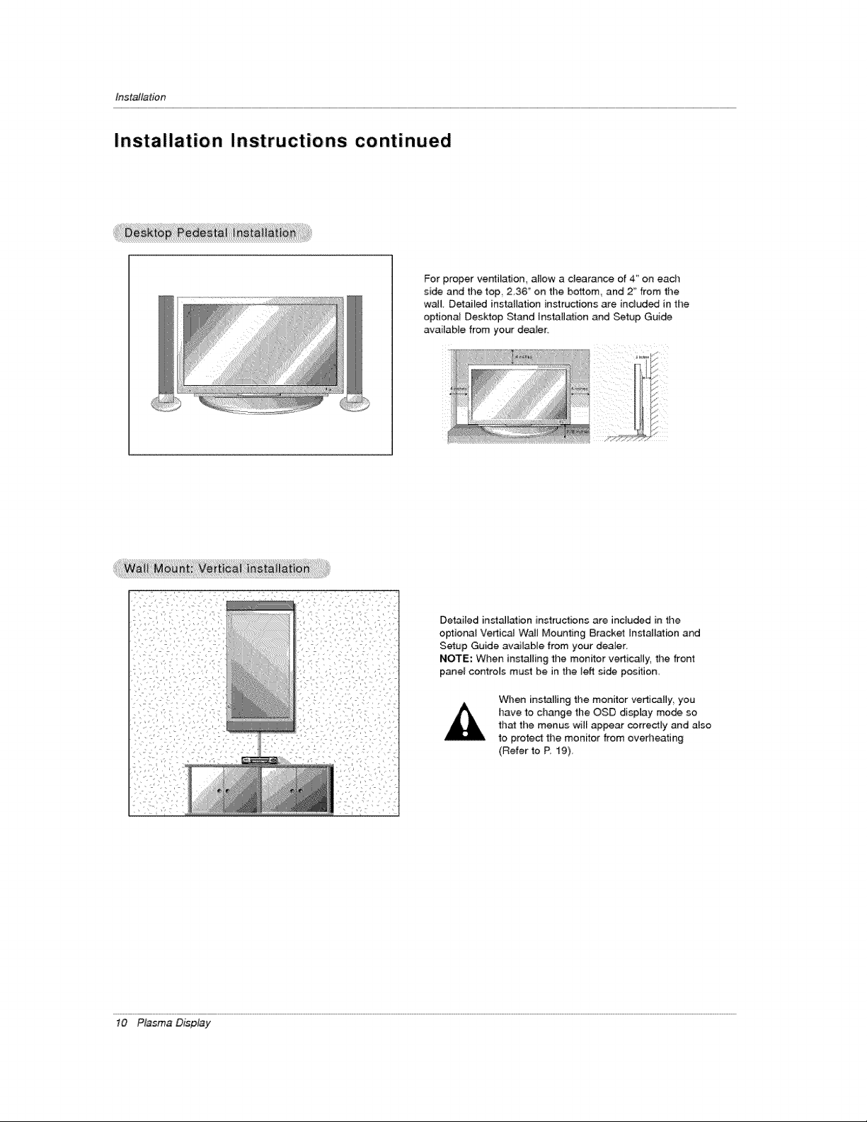
Installation Instructions continued
For proper ventilation, allow a clearance of 4" on ead_
side and the top 2,36 '_on the bottom and 2 _'from time
wail Detailed installation instructions are indud_ in the
optional Deskfop Stand lnsta[i_ion and Setup Guide
available from your dealer,
/I )
[/
_i'!i'!;i;_i;i;w__t_iii;ii_M;!_i_iiti!;!iii!!V!_i!il_!i!;_;!!_;_;;ii!;_!i!_i_i;is!i_;_i!i;_iii i;_i;iiiiiiiiii;;!i!i!ii!ii!ilil;iiiii;ii;:_:
Detailed installation instructions are inc}uded in the
optiona_ Vertical WaJJ Mounting Bracket Installation and
Setup Guide available from your dearer.
NOTE; When installing the monitor verticaJ[y, the front
p_el controls must be in the lefl side position.
When installing the monitor vertically, you
have to change the OSD display mode so
that the menus will appear correctly and also
to proteCt the monitor from overheating
(Refer to R 19)_
10 Plasma Display
Installation
External Equipment Connections
NOTE: Not all cables shown are included with the p|asma display:
- To avoid picture noise (interference) _eave an adequate distance between the VCR and Monitor
Use the ISM Method feature to avoid having a fixed image remain on the screen for a tong period of time. Typically a frozen still
picture from a VCR If time 4:3 picture format is used the fixed image., shown at the sides of the screen, may remain visible on
the screen.
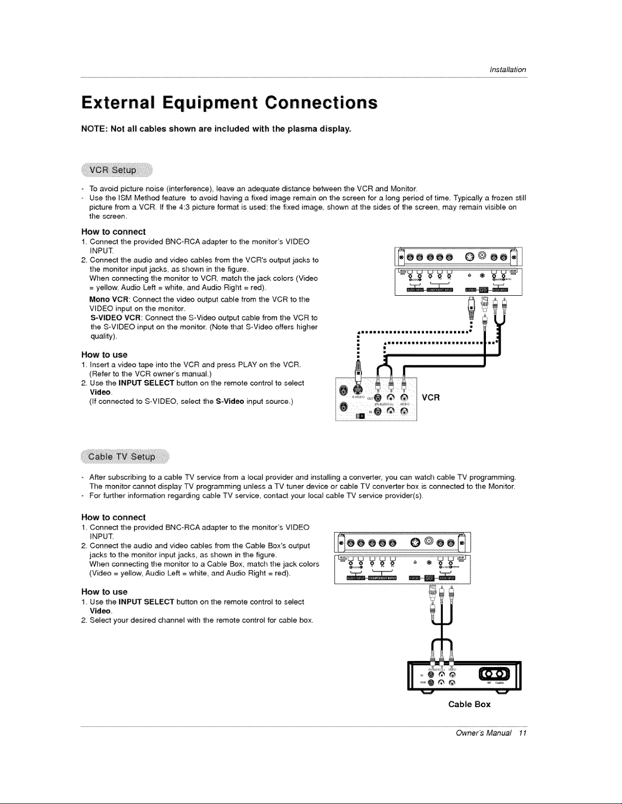
How to connect
1. Connect the provided BNC_RCA adapter to the monitor's VIDEO
iNPUT.
2 Connect the audio and video cables from the VCR's output iacks to
the monitor input iacks, as shown in the figure
When connecting the monitor to VCR, match the jack colors (Video
= ye{_ow, Audio Left = white, and Audio RigI_ = red).
Mono VCR: Connect the video output cable from the VCR to the
VIDEO input on the monitor.
S-VIDEO VCR: Connect the SWideo output cable from the VCR to
the SoWDEO inp_rt on the monitor. (Note that S-Video offers higher
quality)
How to use
1 insert a video tahoe into the VCR and press PLAY on the VCR
(Refer to the VCR owner's manuaL)
2. Use the iNPUT SELECT button on time remote cor4rol to select
Video,
(if connected to S-VIDEO, select the S-Vid_ input source.)
- After subscribing to a cable TV service from a _ocal provider and instal{ing a conveder, you can watch cable TV programming.
The monitor cannot display TV programming unless a TV tuner device or cable TV converter box is connected to the Monitor.
For further information regarding cabie TV service, c_ntact your local cable TV service provider(s).
How to connect
1. Connect the provided BNC°RCA adapter to the monitor's VIDEO
iNPUT
2 Connect the audio and video cables from the CaNe Boxes output
jacks to the monitor input jacks, as shown in the figure
When connecting the monitor to a Cable Box match the jack colors
(Video = yellow, Audio Left = white, and Audio Righ_ = red).
How to use
1. Use the INPUT SELECT button on the remote control to select
Video
2. Select your desired channel with the remote control for cable box_
Cable Box
Owner _ Manual 11
Installation
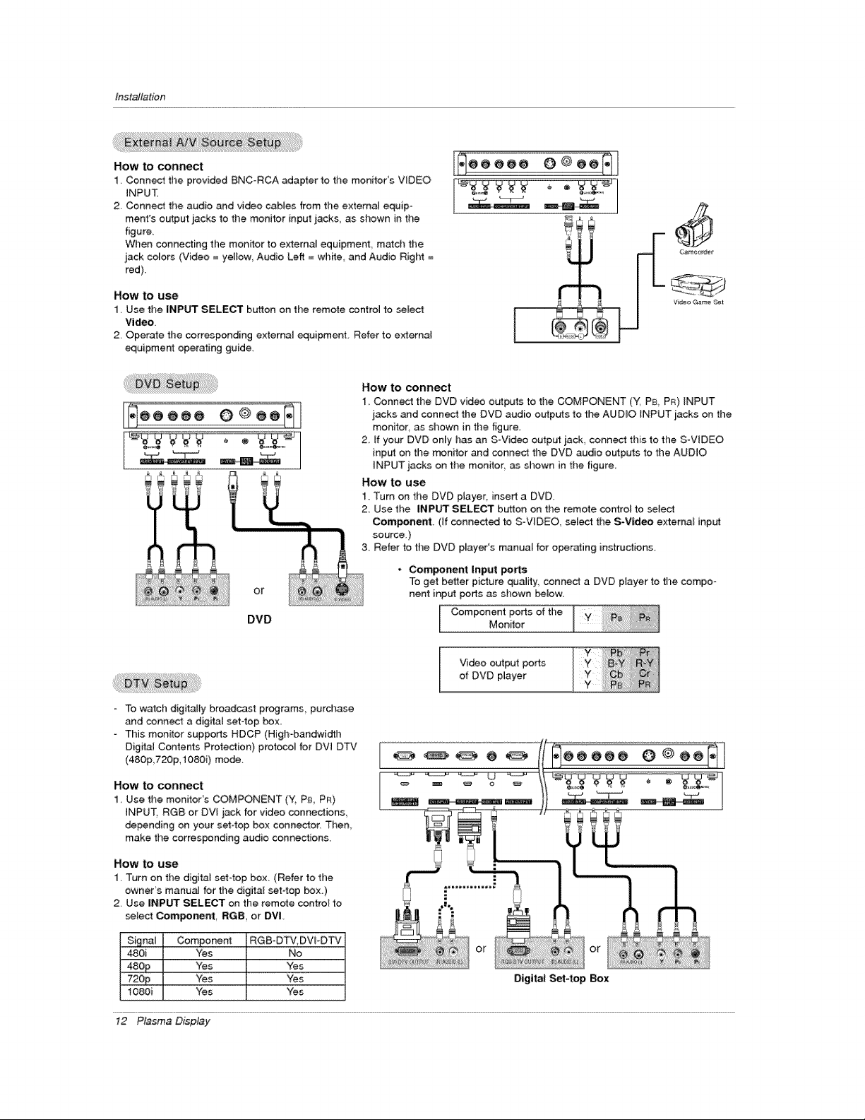
How to connect
1. Connect the provided BNC-RCA adapter to the monitor's V_DEO
iNPUT,
2. Connect the audio and video cables from the external equip-
ment's output jacks to the monitor input iacks, as shown in the
figure.
When connecting the monitor to external equipment, match the
jack colors (Video = yellow Audio Left = wh_e and Audio Right =
red),
How to use
1. Use the INPUT SELECT button on the remote control to select
Video.
2_ Operate the corresponding externaJ equipment, Refer to externat
equipment operating guide,
_ooooo @@oo_
Vt_eo Game S_t
t
How to connect
1, Connect the DVD video outputs to time COMPONENT ('_ PB, PR) iNPUT
jacks and connect the DVD audio outputs to the AUDIO iNPUT jacks on the
monitor, as shown in the figure
2 if your DVD only has an S-Video outp_ jack, connect this to the S°VIDEO
inpLr_on the, monitor and conned the DVD audio outputs to the AUDIO
iNPUT jacks on the monitor, as shown in the figure
HOW tO use
1 Turn on the DVD player, insert a DVD.
2 Use the INPUT SELECT button on the remote control to select
II Component. (If connected to S-VIDEO, select the S-Video external input
I ! source_)
_ 3 Refer to the DVD p_ayer's manual for operating instructions.
• Com_nent Input ports
To get better picture qu_ity, connect a DVD player to the compo-
Or nent input ports as shown below.
Component ports of theDVD Mon_or
To watch digitally broad_st programs, purchase
and connect a digital set4op box,
This monitor supports HDCP (High-bandwidth
Digital Contents Protection} protocol for DVl DTV
(480p 720p,1080i) mode.
[
Video output ports
of DVD player
How to connect
1 Use the monitor's COMPONENT (Y, P& PR)
INPUT. RGB or DVt jack for video connections,
depending on your set-top box connector. Then,
make the corresponding audio connections.
How to use
1. Turn on the digital set-top box (Refer to the
owneCs manuaJ for the digital set-top box)
2. Use iNPUT SELECT on the remote control to
_lec_ Component, RGB, or DVL
480i Yes No
48££ Yes Yes
72££ Yes Yes
1080i Yes "Yes
or
Digital Set4op Box
12 Plasma D_splay
Installation
- This monffar provides Plug and P_ay capabilily, meaning that the PC adjusts automatically to its settings. The monitor sends
configuration information (EDID) to the PC using the Video E_ectronics Standard Association (VESA) Display Dar_ Channel
(DDC) protocol.
Time monitor perceives 6,40x480 60Hz as DTV 480p based on the PC graphic card. In this case,, change time screen scanning
rate for the graphic card.
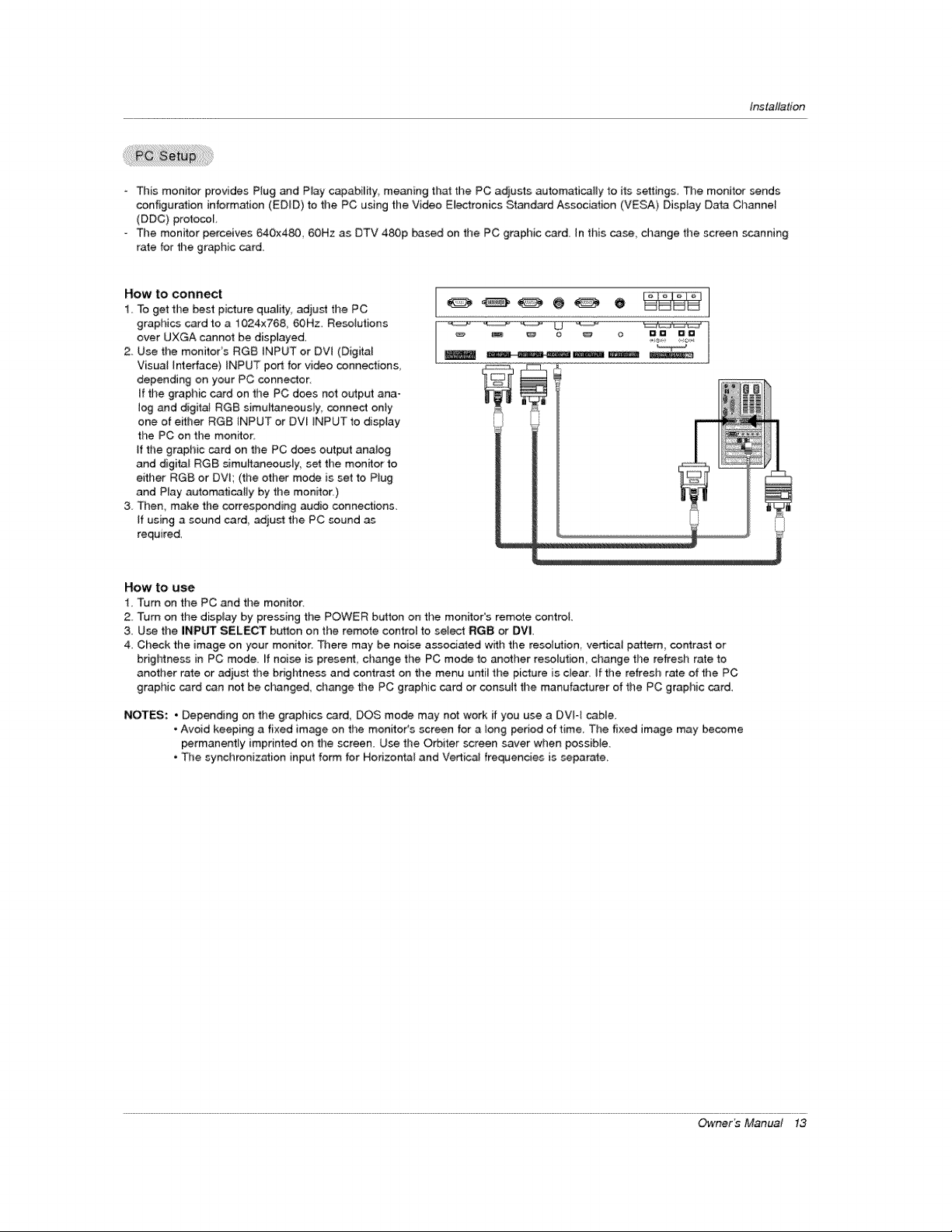
How to connect
1, To get the best picture quality, adiust the PC
graphics card to a 1024x768, 60Hz. Resoiutions
over UXGA cannot be displayed.
2. Use the monitor's RGB INPUT or DVI (Digital
Visual Interface) INPUT port for video connections
depending on your PC connector,
If the graphic card on the PC does not output ana-
log and digital RGB simultaneously, connect only
one of either RGB INPUT or DVI _NPUT to display
the PC on the monitor:
If the graphic card on the PC does outpat analog
and digital RGB simultaneously, set the monitor to
either RG8 or DVI; (the other mode is set to Plug
and Play automatically by the monitor.)
3. Then, make the corresponding audio connections.
If using a sound card, adjust the PC sound as
required.
HOW tO use
1 Turn on the PC and the monitor.
2 Turn on the display by pressing the POWER button on the monitor's remote control.
3 Use the INPUT SELECT button on the remote control to select RGB or DVI
4, Cl_eck the image on your monitor, There may be noise associated w_h the resolution, vertica_ pattern, contrast or
brightness in PC mode. ff noise is present, change the PC mode to another resolution change the refresh rate to
another rate or adjust the brightness and contrast on the menu until the picture is ctear_ if the refresh rate of the PC
graphic card can net be changed, change the PC graphic card or consult the manufacturer of the PC graphic card_
NOTES: • Depending on the graphics card, DOS mode may not work if you use a DVI4 cable.
• Avoid keeping a fixed image on the monitor% screen for a _ong period of time. The fixed image may become
permanently imprinted on the screen. Use the O_iter screen saver when possible.
• The synchronization input form for Horizontal and Vertical frequencies is separate.
Owner _ Manual 13
Installation
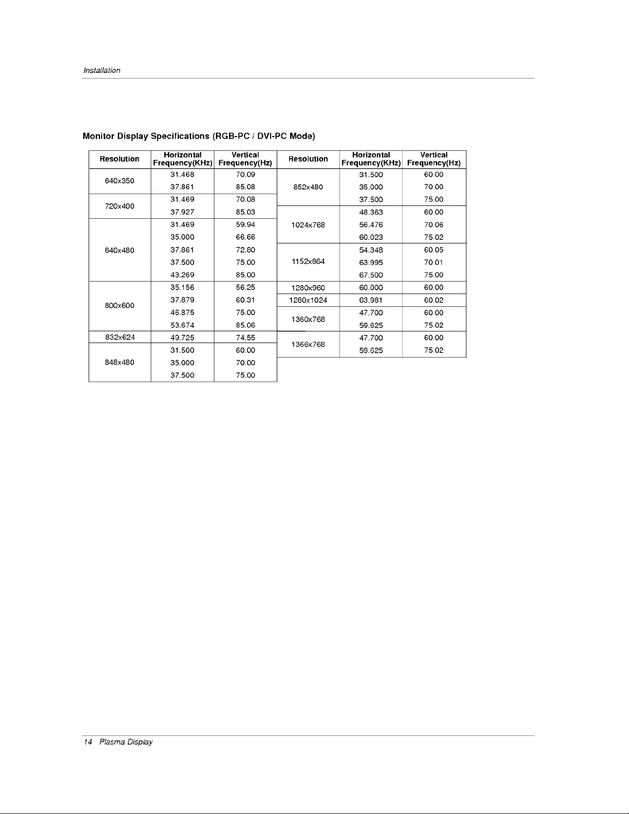
Monitor Display Specifications (RGB-PC / DVI-PC Mode)
Resolution
640x350
720x400
640x480
800x600
832x624
848x480
Horizontal
Frequency(KHz)
31.468
37.861
31.469
37.927
31.469
35.000
37.861
37.500
43.269
35.156
37.879
46.875
53.674
49.725
31.500
35.000
37.500
Vertical
Frequency(H_
70.09
85.08
70.08
85.03
59.94
66.66
72.80
75.00
85.00
56.25
60.31
75.00
85.06
74.55
60.00
70.00
75.00
Resolution
852x480
1024x768
1152x864
1280x960
1280x1024
1360x768
1366x768
Horizontal
Frequency(KHz)
31.500
35.000
37.500
48.363
56.476
60.023
54.348
63.995
67.500
60.000
63.981
47.700
59.625
47.700
59.625
Vertical
Frequency(Hz)
60.00
70.00
75.00
60.00
70.06
75.02
60.05
70.01
75.00
60.00
60.02
60.00
75.02
60.00
75.02
14 Plasma Display
Operation
Turning on the
Monitor
I, Connect power cord correctly,
2 Press the _ ON/OFF button on the Monitor, At this moment, the Monffor is switched to standby
mode. Press the INPUT SELECT button on the Monitor or press the POWER, INPUT SELECT
button on the remote control and then the Monitor wiJ[ switch on,
1. if the Monitor was turned off with the (_ ON/OFF button on the Monitor
* Press the _ON/OFF button on the Monitor to turn the Mon_or on
2, if the Monitor was turned off with the remote control and then the (D ON/OFF button on the Monitor
• Press the CON/OFF button on the Monitor and then press the INPUT SELECT b_ton on the
Monitor or press the POWER, INPUT SELECT button on the remote control to turn the Monitor on.
Language Selection
- The menus can be shown on the screen in the setected language. First select your language,
1 Press the MENU button and tl_en use & / V button to select the SPECIAL menu
2, Press the I_ button a_ then use A / V button to select _gf4Gge,
3, Press the _ button ar_ then use ,I, / V button to select your desired language,
From this point on, the on-screen menus wilt be shown in the language of your choice.
4. Press the OK button to save,
Owner _ Manual 15
Operation
Video Menu Options
Picture menu adjustment are unique to each input source, Readjust Video menu _tt[ngs for each fo{-
[owing input source as preferred_
• RG8 (PC) / DV_ (PC)
• RGB (DTV) / DVl (DTV) / Component (480p 720p 1080i)
• Video / SoVideo / Component (4800
APC adiusts the Monitor for the _st picture appearance.
- When adiusting Video menu options (contrast, brightness, color, sharpness and tire) manualiy, APC automatically
changes the setting to User
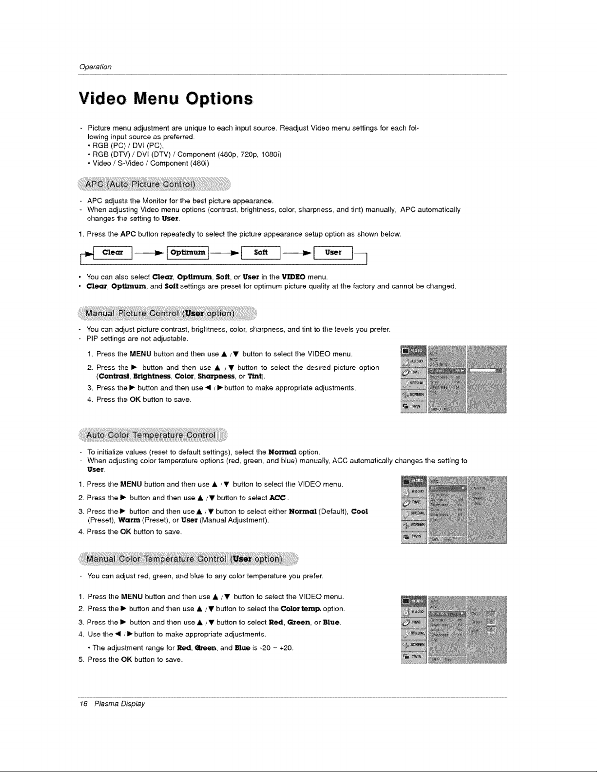
1 Press the APC button repeatedly to select the picture appearance setup option as shown below,
c,eo, ,o,, ""t--q
• You can a_so select Clear, Optimum, Soft, or User in the VIDEO menu.
• Cl_, Optimum, and Soft settings are preset for optimum picture quaJity at the factory and cannot be changed,
You can adjust picture cor_trast, brightness_ color, sharpness, and tint to the leve_s yo_ prefer_
PIP settings are not adiustab_e.
1. Press the MENU button and ti_en use ,_, _V button to select the VIDEO menu
2. Press the i_ button and then use A / V button to select the _sired picture option
(Contrast B_ghtne_, CoL_ Sharpness, or _*_t).
& Press thel_ button and then use <1 tl_ button to make appropriate adjustments
4. Press the OK button to save.
To initialize values (reset to defauff settings), _ted the Nutmal option
- When adiusting color temper_ure options (red, green and blue) manually ACC automatically changes the setting to
User.
1 Press the MENU button and then use & _V bLr_ton to select the VIDEO menu.
2. Press the I_ button and then use A JV button to select _C.
3. Press the i_- button and then use A ,_V button to select either Normal (Default), Cool
(Preset)_ Warm (Preset), or User (Manua_ Adjustment)
4. Press the OK b_ton to save.
- You can adjust red, green, and blue to any color temperature you prefer,
1. Press the MENU button and then use A iV button to select the V_DEO menu,
2. Press the liD"button and then use A i V button to select the Coiot temp. option.
3. P_ess the I_ button and then use _ i V button to select R_, Green, or Blue
4. Use the < / I_ button to make appropriate adjustments.
• The adjustment range for _, Green_ and Blue is -20 -_+20
5 Press the OK button to save,
16 P_sma D_p_y
Operation
Audio Menu
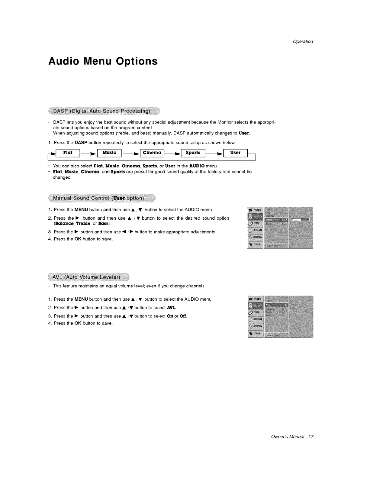
DASP lets you enjoy the best sound without any special adjustment because the Monitor selects the appropri-
ate sound options based on the program content,
- When adjusting sound options (treble, and bass) manually. DASP automatically changes to User.
1 Press the DASP button repeatedly to selecl the appropriate sound setup as shown below,
• You can also _lect Flat Music Cinema Sports or I/sex in the A_IO menu
Mat Music Cinema _d S_tts are preset for good _und quality at the factory and cannot
changed,
1. Press the MENU button and then use A/V barton to sel_t the AUDIO menu.
2, Press the !_ button and then use A / V button to select the desired sound option
3, Press the I_ button and then use </1_ button to make appropriate adjustments,
4 Press the OK button 1o save
- This feature maintains an equaJ volume level; even if you change channels.
1, Press the MENU barton and then use A ,_V buffton to select the AUDIO menu,
2 Press the i_ button and then use A _' button to select A_L
3 Press the I_ button and then use A _ V button to seiecl On or Off,
4. Press the OK button to save
Owner _ Manual 17

Operation
Time Menu Options
if current time soiling is wrong, reset the ciock.
1. Press the MENU button and then u_ ,& iV button to select timeTIME menu.
2. Press the lib button and then use &/V b_on to select Clock
3. Press the I_ button and then use &/V b_on to set the hour.
4. Press the i_ button and then use A/Y bL_on to set the minutes_
5, Press the OK button to save.
- Timer function operates only if current time has been set.
° Off-Timer function overrides On=Timer function if they are both set to the same time.
1. Press the MENU button and then use k/V button to select the TIME menu
2 Press the I1_button and then use & tV button to select Oil t_r or On tL_er
3, Press the I_ button and then use & tV button to select On,
• To canceJ OniOff f_er function, selec_ C_f.
4. Press the I_ button and then use A _V button to set the hour.
5, Press the I_ button and then use A /V b_on to set the minutes,
6, For On Umex function only, press the I_ button and then use & V button to set
the volume _evel at turn on
7 Press the OK button to save.
- If tltere is no input signal the Monitor turns off automatically after 10 minutes
1 Press the MENU button and then use A _,V button to select the TIME menu
2. Press the I_ bull!on and then use A/V butch to select Auleo_
3. Press the I_ button and then use A / V bu_on to se_ct _ or _,
4 Press the OK button to save.
The sleep timer turns the Monffor off at a preset time. Note that this _tting is cleared when the monitor is turned off.
1 Press the SLEEP button repeatedly to selec_ the number of minutes, First the _ --- _ option _aJ-s on the
screen, followed by the following sleep timer options: i0, 20, 30 60, 90, i20 180 and 240 minutes.
2. When the number of minutes you want is displayed on the screen press the OK button. Time timer begins to cou_
down from the number of minutes selected.
3. To check the remaining minutes before the monitor turns off, press the SLEEP or OK button once
4. To cance_ the S_p Timer, press the SLEEP button repeatedly until _-- _ appea_.
18 P_sma D_p_y
Operation
Special Menu Options
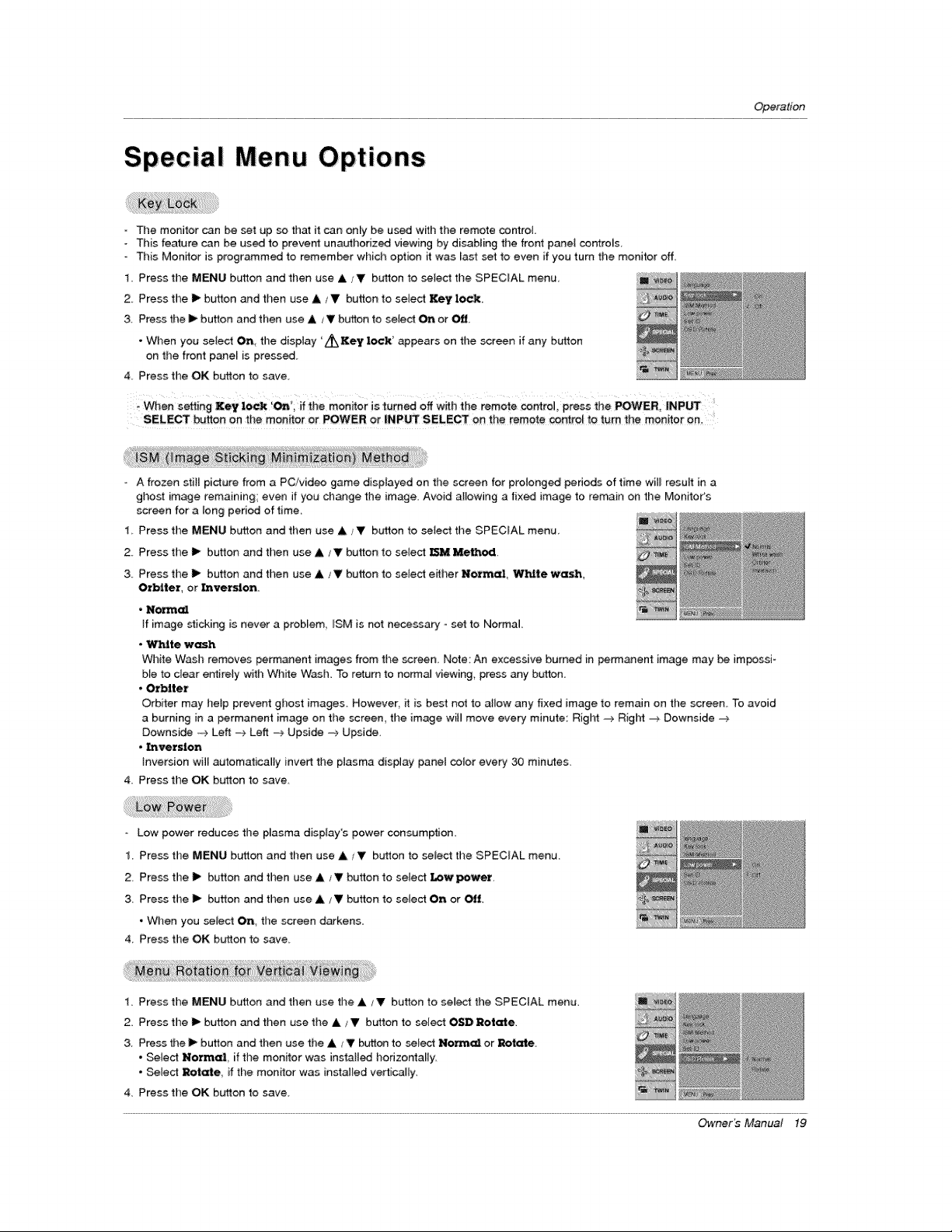
° The monitor can be set up _ that it can only be used with the remote control.
- Tt_is feature can be used to prevent unauthorized viewing by disabling the front panel controls
- This Mon_tor is programmed to remem_r which option it was last set to even if you turn the monitor off.
1. Press the MENU button and tllen use A / V button to seJect the SPECIAL menu,
2. Press time I1_button and then use & ,_V button to setect Key lock.
3. Press the _ button and then use A / V button to setect On or _.
• When you sele_ On, the dispiay 'L_KeY lock' appears on the screen if any button
on the front panel is pressed.
4, Press time OK button to save.
When setting Xe¥ lock 'On; if the monitor is _umed off with the remote _ntrol press the POWER, _NPUT
SELECT button on the men,or or _WER or |NpuT SELE_ on the remote co_ro_ to turn the monitor on,
- A frozen still picture from a PC!video game displayed on the screen for prolonged penods of time will resu4t in a
ghost image remaining; even if you change the image. Avoid allowing a tix_ image to remain on the Monitor's
screen for a Ieng penod of time,
1, Press time MENU button and then use A/V button to select the SPECIAL menu,
2. Press the I_ button and then use A/V button to select: _ Me_e,d
& Press the I_ button and then use A V button to select e_her Normal, _.lte wash,
Orbiter or Lnvexsion
• Non_cd
if image sticking is never a problem ISM is not necessa_ - set to Normal
• _te wash
White Wash removes permanent images from the screen Note An excessive burned in permanent image may be impossi-
ble to clear entirely with White Wash To return to norma_ viewing, press any button.
• Orbiter
Orbiter may hetp prevent ghost images. However, it is best not to a_ow any fixed image to remain on the screen. To avoid
a burning in a permanent image on the screen, the image will move every minute: Right -:_ Right _ Downside -_
Downside _ Left =_ Left -> Upside -> Upside,
• _version
Inversion will automatically invert the plasma dispiay _3nel co_or eve_ 30 minutes.
4. Press the OK button to save
Low power reduces the p_asma disp_ay's power consumption.
1 Press the MENU button and then use A / V button to select the SPECIAL menu
2. Press the I_ bufton and then use A _Y button to setect f_wpewez.
3. Press the _ button and then use A t_' button to select On or Off.
• When you select On the screen darkens
4 Press the OK button to save.
1. Press the MENU burton and then use the _ _!' button to select the SPECIAL menu.
2, Press the I_ button and then use the & _V button to select OSD Rotate,
3. Press the _ button and then use the _ _T _tton to select N_ or Rotate.
• Select Normal if the monitor was installed horizontally
• Sele_ Rotate, if the monitor was instal_ed vedical_y,
4. Press the OK b_ffton to save
Owner _ Manual 19
Operation
Screen Menu Options
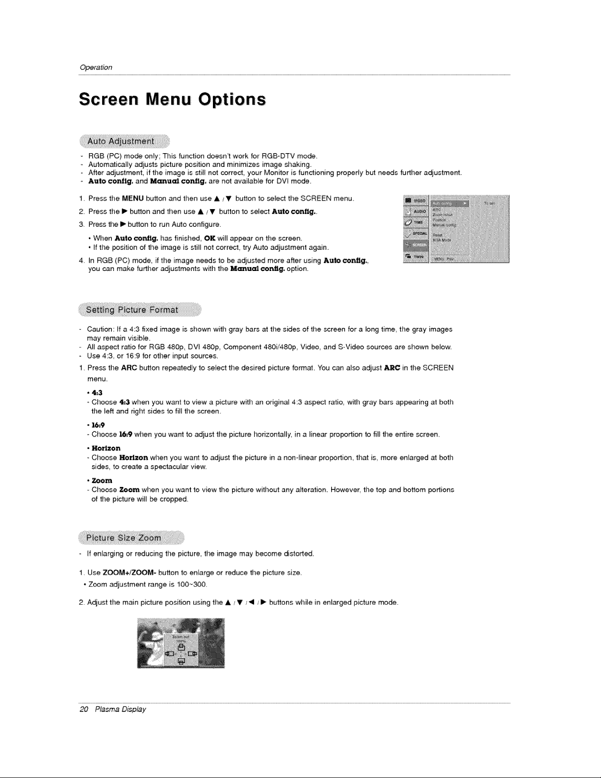
RGB (PC) mode only; This function doesn't work for RGB-DTV mode.
- Autom_ical_y adjusts picture position and minimizes image shaking
- After adjustment, if the image is still not correct, your Monitor is fundioning properly but needs fudher adjustment.
- Auto ¢onflg, and Manu_ ¢onflg, are not available for DVI mode.
1. Press the MENU button and tl_en use A/V button to select the SCREEN menu
2. Press the I_ button and then use A ,,V button to sele_ &uloconflg.
3, Press the i_ button to run Auto configure.
• When Auto ¢o_'_g, has finished, OK, wiI_ appear on the screen_
• tf the position of the image is stiI_ not correct, try Auto adjustment again.
4. in RG8 (PC) mode, if the image needs to be adjusted more after using Auto cor,_g,,
you can make further adjustme_s w_h the M[emued conflg, option,
Caution: If a 4;3 fixed image is shown with gray bars at the sides of the screen for a tong time, tile gray images
may remain visible.
All aspect ratio for RGB 480p, DVt 480p, Component 480i/480p, Video, and S-Video sources are shown below.
- Use 4:3, or _6:9 for other input sources
1. Press the ARC button repeatedmy to select the desired picture format:. You can also adjust ARC in the SCREEN
menu.
• 4;3
° Choose 4.'3 when you want to view a picture with an original 4:3 aspect ratio, with gray bars @pearing at beth
the left and right sides to fill the screen
• 1_9
Cl_oose 16_9 when you want to adjust the picture horizontally, in a _inear pro_rtion to fiti the entire screen.
• Horizon
Choose _rizon wben you wa_ to adiust the pidure in a non-finear proportion, that is_ more enlarged at both
sides, to create a spectacular view
• Zoom
- Choose _om when you want to view the picture without any alteration. However, the top and bottom potions
of the picture wH_ be cropped.
If enlarging or reducing the picture, the image may become distorted.
1. Use ZOOM+/ZOOM- button to enlarge or reduce the pi_ure size.
* Zoom adjustment range is 100~30&
2. Adjust the main picture position using the A / V / 4 / I_ buttons while in enQarged picture mode.
20 P_sma D_p_y
Operation
- Enlarges the picture in correct proportions
- Split Zoom can be used for a_l input sources.
- In 2-Split Zoom m_e, you can only move the image up or down
if a screen is enlarged, a screen can move w_thout selecting s_t[on of screen Sprit Zoom.
- It's not available to use this function if OSD Rotate is set to the Rotate option
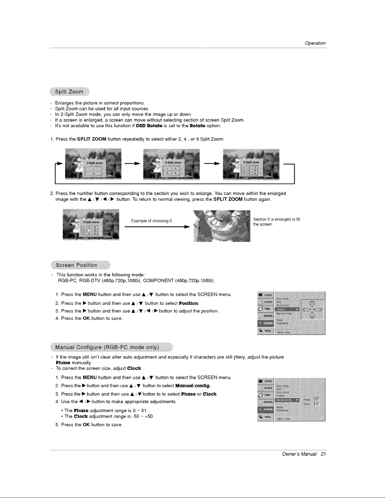
1, Press the SPLIT ZOOM button repeatedly to select either 2 4, or 9 Split Zoom,
2. Press the number b_4ton corresponding to the s_ion you wish to enlarge. You can move w_thin the enlarged
image with the ,IM/V _,_11/l_ button. To return to no_a_ viewing, press the SPLIT ZOOM button again.
Example of c_oosir_ 5.
Soctior_ 5 is er_larged to fill
the screen,
o This function works in the fo_owing mode:
RGB-PC, RGB-DTV (480p,720p,t080i), COMPONENT (480p,720p,1080i).
1. Press the MENU button and then use A/V button to select the SCREEN menu.
2. Press the lip button and then use & _V button to select Position
3. Press the I_ bLrLton and then use A / T j_ll/1_ b_on to adjust the position.
4. Press the OK button to save
- If the image stil_ isn't dear after auto adjustment and espiedaHy if characters are still iittery,, adiust the picture
Phase manually,
To correct the screen size, adjust Clock,
1. Press the MENU button and then use & _' button to select the SCREEN menu.
2 Press the I1_burton and then use A _V button to select Manue_ cenflg.
& Press the II_ button and then use & _ V bt_r_on to to select Phase or Clock,
4_ Use the "41/ I1_button to make appropriate adjustments
• The Ph_ adiustment range is 0 "- 31
• _e Clock adjustment range is -50 ~ +50.
5. Press the OK button to save
Owner_ Manual 21
Operation
Screen Menu Options continued
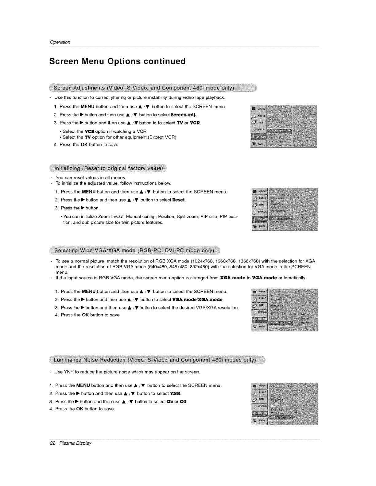
Use this function to correct ifftering or picture instability during video tape ptayback
1. Press the MENU button _d then use A/V button to select the SCREEN menu
2 Press the I_ button and then use & V button to seEect $¢reen edJ,
& Press #_e I_ button and then use A/V button to to select 'rv or VCR.
• Select the VCR option if watching a VCR_
• Select the TV option for other equipmenL(Except VCR)
4. Press the OK button to save,
You can reset values in atl modes
To initialize the adjusted va_ue, fotlow instructions below
I. Press the MENU button and then use A / V button to select the SCREEN menu
2 Press the I_ button and then use A/V button to sel_ Reset.
3. Press the I_ button.
• You can initialize Zoom _n/OuL Manu_ config. Position Sp_it zoom PIP size PiP _sio
tion and sub picture size for twin picture features
To see a no_a_ picture match the resolution of RGB XGA mode (1024x768, 1360x768, 1366x768) with the seJection for XGA
mode and the resolution of RGB VGA mode (640x480,, 848x480, 852x480) with the selection for VGA mode in the SCREEN
menu,
ff the input source is RGB VGA m_e the screen menu option is changed from XGA mode to VGA mode automatically.
I. Press the MENU button and then use A/V button to setect the SCREEN menu.
2. Press the I_ button and then use ,L ,,V bulton to select VGA mede/XaA mode.
3 Press the t1_button and then use ,&/V button to select the desired VGA/XGA resolution.
4. Press the OK button to _ave.
Use YNR to reduce the picture noise which may appear on the screen.
1. Press the MENU button and then use A iV button to seJect the SCREEN menu_
2. Press the I1_button and then use A/V butl!on to select YNR
3, Press the I_ button _d then use A / Y button to selest On or Off
4 Press the OK button to save
22 P_sma D_p_y
Operation
PIP (Picture-in-Picture)Feature
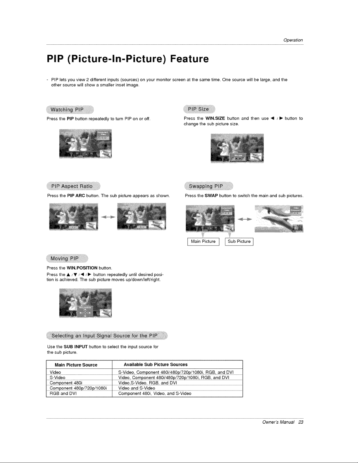
o PIP lets you view 2 different inputs (sources) on your monitor screen at the same time. One source will be large and the
other source will show a smalter inset image.
Press the PaP button repeatedly to turn PIP on or off,
Press the WIN.SIZE button and then use 4 _1_ button to
change the sub picture size.
Press the PIP ARC button. Tile sub picture appears as shown, Press the SWAP button to switcll the main and sub pictures,
ILMainPictu oJ [SubPicture]
Press the WIN.POSITION bu_ton,
Press the A ,_V _11 /I_ button repeatedly until desired posi-
tion is acl_ieved, The sub picture moves up/down/Felt/right,
Use the SUB INPUT button to select the input source for
the sub picture
Main Picture Source Available Sub Picture Sources
.......Y!d_.............................................................................................................................................._:Y!_£, _0m_n_ _ ....................
S-Video videoComponent 4801/480_720p/1080i RGB and DV]
.......Component 480i ...............Vid#o,S-Vide£ .........................................................................................................................................................
....... .......................Vid_ artd #:yide ?...................................................................................................................................................................................................
RGB and DVl Component 480i, Video, and S-Video
Owner b Manual
Operation
Picture Setup Option
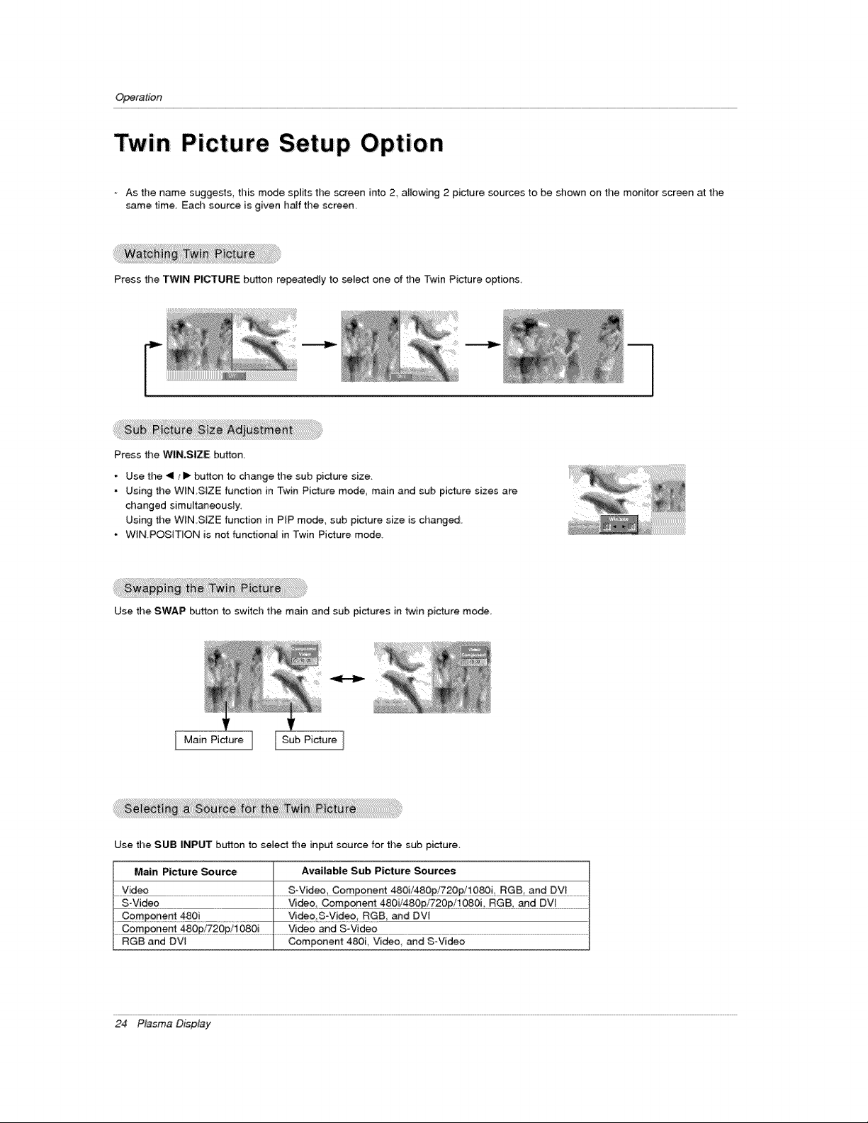
As the name suggests, this mode splits the screen into 2 altowing 2 picture sources to be shown on the monitor screen at the
same time, Each source is given half time screen.
Press the TWiN PICTURE b_,'tton repeatedly to select one of time Twin Picture options,
Press the WIN,SIZE button.
Use the _!1_ I_ button to dlange the sub picture size,
Using the W_N,S[ZE function in Twin Pidure mode, main and sub picture sizes are
changed simultaneously,
Using the WIN,SIZE function in P_P mode, sub picture size is change.
WIN.POSITION is net functionaJ in Twin Picture mode,
Use the SWAP button to switch the main and sub pictures in twin picture mode.
Main Picture Sub Picture
Use the SUB INPUT button to select the input source for the sub picture,
Main Picture _urce Available Sub Picture Sources
Video S-Video, Component 480i/48 10_!_ .....................
_ CQmpo£ent 48£! ......................... Video SV!deo RGB and DV[
....... £p/Z2Op,!l#8£! ..........................Vid Vide£ ...........................................................................................................................................................................................................................
RGB and DV[ Component 480i Video and SoVideo
24 P_sma D_p_y
ExternalControlDeviceSetup
External Control Device Setup
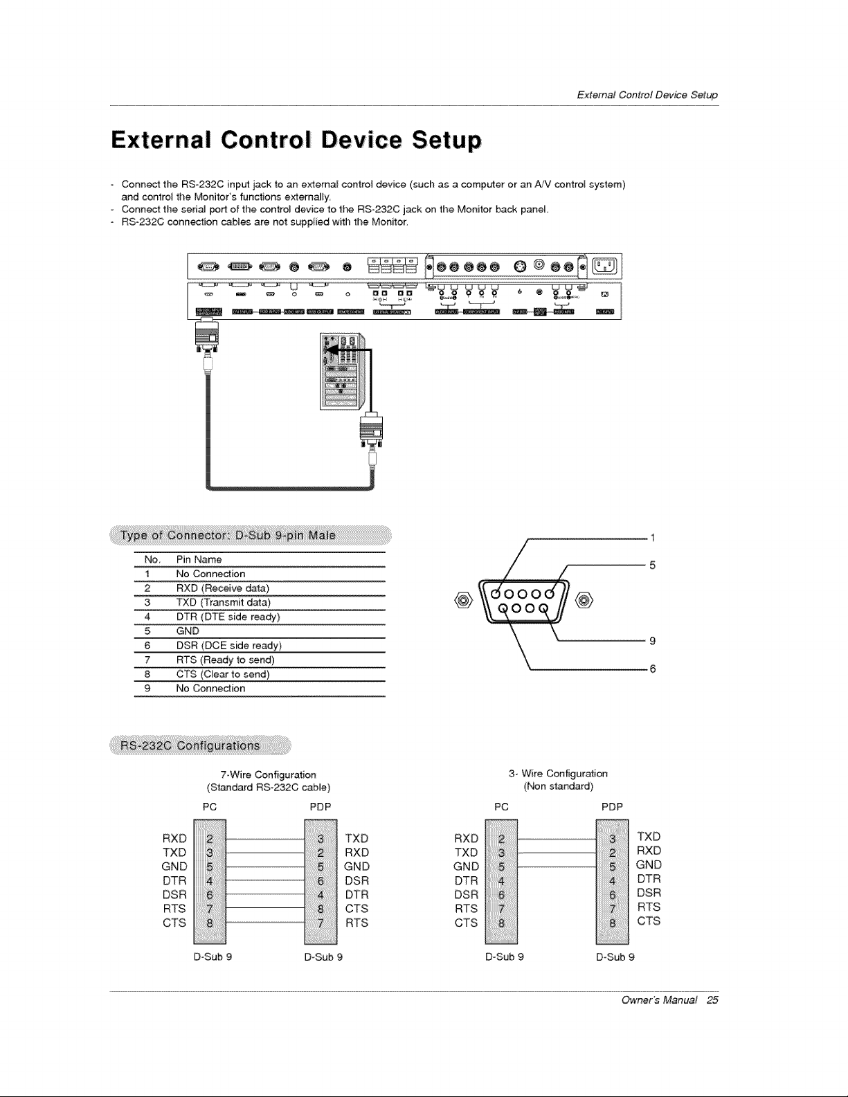
° Connect the RS-232C inp_ jack to an external control device (such as a computer or an AiV con#ol system)
and contro{ the Monitor's functions externally
- Connect the sedd port of the control device to the RS-232C jack on the Monitor back panel,
RS-232C conn_ion cables are not supplied with the Monitor,
1
/
No, Pin Name / 5
1 No Connection ......
2 RXD (Receive data) _ @
3 TXD (Transmit data) @
4 DTR (DTE side ready)
5 GND
6 DSR (DCE side ready) 9
7 RTS (Ready _o send)
8 CTS (Ctear to send) 6
9 No Connedion
RXD
TXD
GND
DTR
DSR
RTS
CTS
7-Wire Configuration
(Standard RS-232C cable)
PC PDP
3::::
6:
D=Sub
TXD RXD
RXD TXD
GND GND
DSR DTR
DTR DSR
CTS RTS
RTS CTS
3- Wire Configuration
(Non standard)
PDP
TXD
RXD
GND
DTR
DSR
RTS
CTS
PC
!iiiiiiiiiii_i%ii_iiii
D-Sub 9
D-Sub 9 DoSub 9
Owner_ Manual 25
ExternalControlDeviceSetup
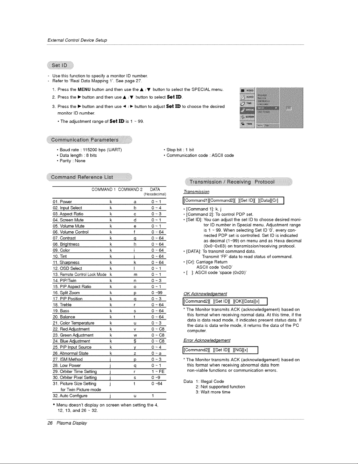
- Use this function to specify a monitor ID number:
Refer to 'Real Data Mapping 1L See page 27
1 Press the MENU button and then use the & zV button to select the SPECIAL menu.
2. Press the I_ button and then use &/V button to select Set
3 Press the i_ button and then use _1 / i_ button to adjust Set _ to choose the desired
monitor ID number.
, The adjustment range of Set iD is 1 _ 99.
• Baud rate : 115200 bps (UART)
• Data lengtl_ : 8 bits
• Parity : None
° Stop bit : 1 b_
• Communication co_ : ASCII code
COMMAND 1 COMMAND 2 DATA
(!_xadecims)
01 Power k a 0 _ 1
02 !nput Select k b 0 _ 4
03. As_ Ratio k c 0 _ 3
04, Screen Mute k d 0 _ 1
O& Volume Mute k e 0 _ 1
O& Volume Cor_trot k f 0 '_ 64
07. _ntrast k ,q 0 _ 64
08 Bdgt_ss k h 0 _ 64
O& Cobr k i 0 _-64
10, lint k j 0 "_ 64
11 Sh&"pness k k 0 ~ 64
12. OSD Select k I 0 _ 1
13 Remote C_ntro_ Lock Mode k m 0 _ 1
14. PIP/Twin k n 0 _ 3
15 P{PAs_ Rat# k o 0 _
16 Sp_it Zoom k p 0 _99
17 PiP Portion k q 0 - 3
l& Treble k r 0 _ 64
19. Bass k s 0 _ 64
20. Balance k t 0 _ 64
21. _br Temperature k u 0 '_ 3
22, Red Adjustment k v 0 "_C8
23 GreenA_usffment k w 0 _-C8
24, Blue Adiustment k $ 0 -
25. PiP _nput Source k y 0 -_4
26, Abnorma_ State k z 0 _ a
27, ISM Method j p 0 _ 3
28, Low Power j q 0 ._ 1
_. O_iter ]]me Setting j r 1 -_ FE
30, O_er Pixe] Setting j s 0 _9
31. Pi_re _ze Setting j t 0 _-64
for Twin P_ure mode
32. Auto Configure. j u 1
" Menu doesn't display on screen wl_en setting the 4,
12 13, and26~32
Transmission
[Cemmand 1]: k, j
* [Command 2]: To centret PDP set
[Set _D[: You can adjust the set iD te choose desired moni-
tor iD humor in Special menu. Adjustment range
is 1 _ 99. When seiecting Set {D '0, every con-
nected PDP set is cer_rol}ed. Set ID is indicated
as decima_ (1"_99) on menu and as Hexa decima{
(OxO,_Ox63) on transmission/receiving protoooL
[DATA]: To transmit command dat&
Transmit 'FF' data to read status of command.
* [Crl: Carriage Return
ASCII code 'OxOD'
* [ ]: ASCII code s_ce (Ox20)'
OK Acknowledgement
J[C,ommand21[ ][Set _D][ ][OKl[Data]{x] !
* The Monitor transmits ACK (acknowledgement) based on
this format when receiving normal data. At this time, if the
data is data read mode it indicates present status data. if
the data is data write mode, it returns the data of the PC
computer.
Error Acknowledgement
_[Cemmand2][ [[Set IDI[ ][NG][x] l
* The Monitor transmits ACK (acknowledgement) based on
this format when receiving abnorma_ d_a from
non-viable functions or communication errors_
Data 1: lil_at Cede
2: Net supported function
3: Wait more time
26 P_sma D_p_y
ExternalControlDeviceSetup
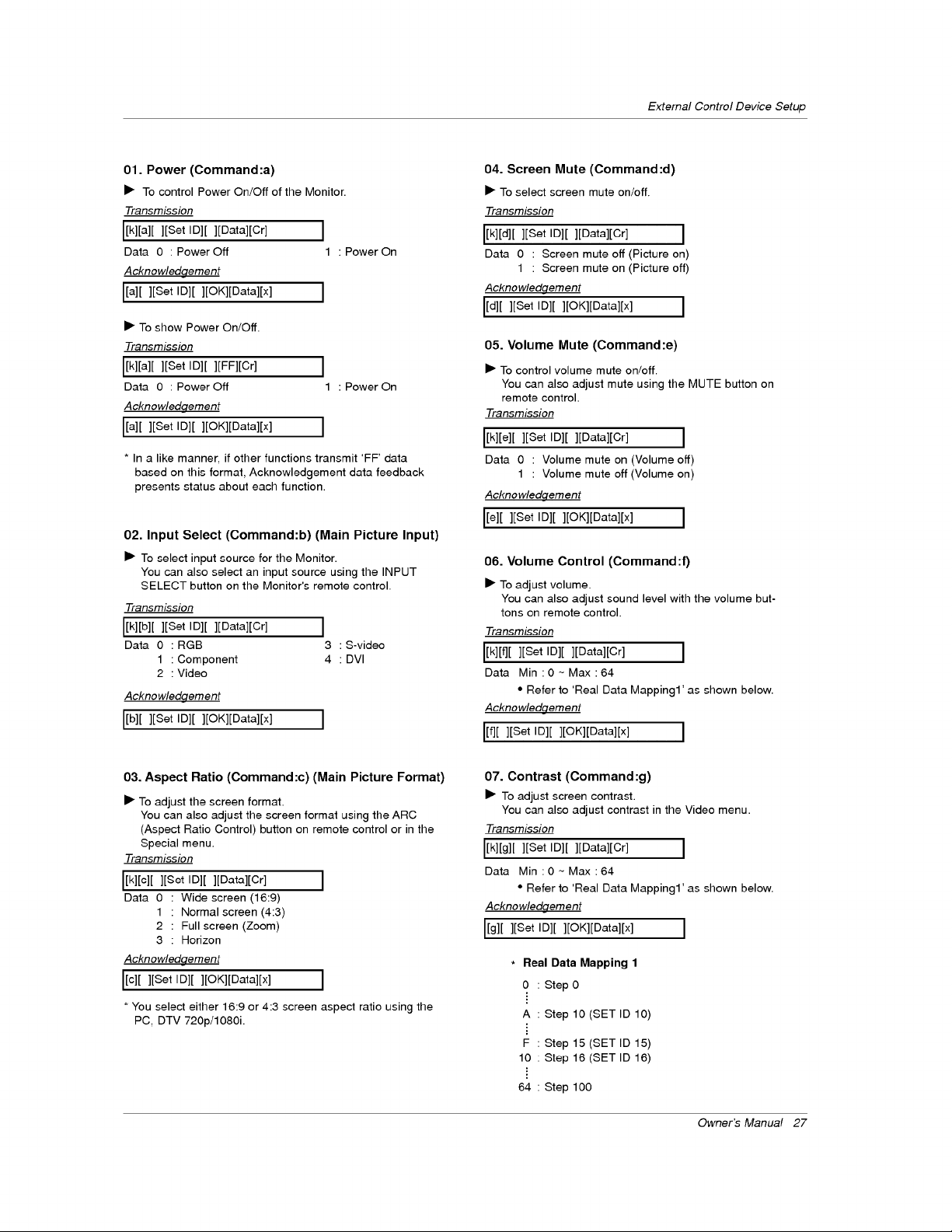
01. Power (Command:a)
I_ To control Power On/Off of the Monitor.
Transmission
[[k][a][ ][Set Ig][ ][gata][Cr] ]
Data 0 : Power Off 1 : Power On
Acknowledgement
[[a][ ][Set Ig][ ][OK][gata][x] ]
I_ To show Power On/Off.
Transmission
[[kl[a][ ][Set Ig][ ][FFl[Cr] ]
Data 0 : Power Off 1 : Power On
Acknowledqement
[[a][ ][Set ID][ ][OK][Data][x] ]
* In a like manner, if other functions transmit 'FF' data
based on this format, Acknowledgement data feedback
presents status about each function.
02. Input Select (Command:b) (Main Picture Input)
I_ To select input source for the Monitor.
You can also select an input source using the INPUT
SELECT button on the Monitor's remote control.
Transmission
L[k][b][ ][Set ID][ ][Data][Cr] ]
Data 0 :RGB 3 :S-video
1 : Component 4 : DVl
2 : Video
Acknowledgement
[[b][ ][Set ID][ ][OK][Data][x]
04. Screen Mute (Command :d)
I_ To select screen mute on/off.
Transmission
[[k][d][ ][Set Ig][ ][gata][Cr] J
Data 0 : Screen mute off (Picture on)
1 : Screen mute on (Picture off)
Acknowledgement
[[d][ ][Set Ig][ ][OK][gata][x] ]
05. Volume Mute (Command:e)
I_ To control volume mute on!off.
You can also adjust mute using the MUTE button on
remote control.
Transmission
[[k][e][ ][Set ID][ ][Data][Cr] J
Data 0 : Volume mute on (Volume off)
1 : Volume mute off (Volume on)
Acknowledgement
L[e][ ][Set Ig][ ][OK][gata][x] J
06. Volume Control (Command :f)
I_ To adjust volume.
You can also adjust sound level with the volume but-
tons on remote control.
Transmission
L[k][f][][Set ID][ ][Datal[Cr] j
Data Min0~Max64
• Refer to 'Real Data Mapping1' as shown below.
Acknowledgement
[[f][ ][Set ID][ ][OK][Data][x] ]
03. Aspect Ratio (Command:c) (Main Picture Format)
I_ To adjust the screen format.
You can also adjust the screen format using the ARC
(Aspect Ratio Control) button on remote control or in the
Special menu.
Transmission
[[k][c][][SetIDI[ ][Data][Cr] J
Data 0 • Wide screen (16:9)
1 • Normal screen (4:3)
2 : Full screen (Zoom)
3 : Horizon
Acknowledgement
[[c][ ][Set Ig][ ][OK][gata][x] ]
* You select either 16:9 or 4:3 screen aspect ratio using the
PC, DTV 720p/1080i.
07. Contrast (Command:g)
ill" To adjust screen contrast.
You can also adjust contrast in the Video menu.
Transmission
[[k][g][ ][Set Ig][ ][gata][Cr] J
Data Min 0~Max64
• Refer to 'Real Data Mapping1' as shown below.
Acknowledgement
[[g][ ][Set Ig][ ][OK][gata][x] ]
* Real Data Mapping 1
0 Step 0
A Step 10 (SET ID 10)
F Step 15 (SET ID 15)
10 Step 16 (SET ID 16)
64 Step 100
Owner's Manua! 27
ExternalControlDeviceSetup
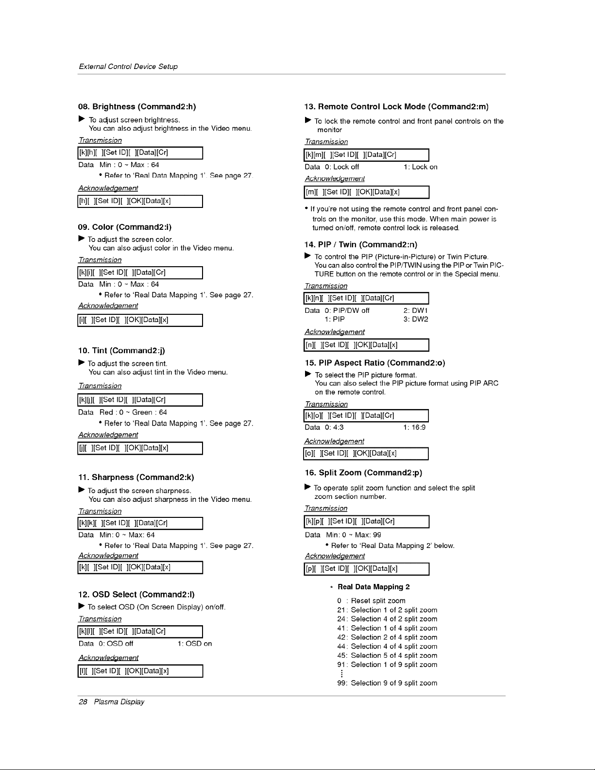
08. Brightness (Command2:h)
• To adjust screen brightness.
You can also adjust brightness in the Video menu.
Transmission
I[k][h][ ][Set ID][ ][Data][Cr] ]
Data Min :O~Max:64
• Refer to 'Real Data Mapping 1' See page 27
Acknowledgement
I/h]/ ][Set ID][ ][OK][Data][x] ]
09. Color (Command2:i)
• To adjust the screen color.
You can also adjust color in the Video menu.
Transmission
IN/i]/ ][Set ID][ ][Data][Cr] I
Data Min:0~Max:64
• Refer to 'Real Data Mapping 1'. See page 27.
Acknowledqement
I/i]/ ][Set ID][ ][OK][Data][x] I
10. Tint (Command2:j)
• To adjust the screen tint.
You can also adjust tint in the Video menu.
Transmission
I[k]ll][ ][Set ID][ ][Data][Cr] ]
Data Red:0~Green :64
• Refer to 'Real Data Mapping 1'. See page 27.
Acknowledgement
I/j] [ ][Set ID][ ][OK][Data][x] I
11. Sharpness (Command2:k)
• To adjust the screen sharpness.
You can also adjust sharpness in the Video menu.
Transmission
I[k][k][ ][Set ID][ ][Data][Cr] ]
Data Min: 0 ~ Max: 64
• Refer to 'Real Data Mapping 1'. See page 27.
Acknowledgement
I/k]/ ][Set ID][ ][OK][Data][x] ]
12. OSD Select (Command2:l)
• To select OSD (On Screen Display) on!off.
Transmission
IN/I]/ ][Set ID][ ][Data][Cr] I
Data 0:OSDoff l:OSDon
Acknowledaement
[[I][ ][Set Ig][ ][OK][gata][x] J
28 P_sma D_p_y
13. Remote Control Lock Mode (Command2:m)
• To lock the remote control and front panel controls on the
monitor
Transmission
[[k][m][ ][Set ID][ ][Data][Cr] ]
Data 0: Lock off 1 : Lock on
Acknowledgement
I/m]/ ][Set ID][ ][OK][Data][x] ]
• If you're not using the remote control and front panel con-
trois on the monitor, use this mode. When main power is
turned on!off, remote control lock is released.
14. PIP / Twin (Command2:n)
• To control the PIP (Picture-in-Picture) or Twin Picture.
You can also control the PIP/TWIN using the PiP or Twin PIC-
TURE button on the remote control or in the Special menu.
Transmission
IN/n]/ ][Set ID][ ][Data][Cr] I
Data O: PIP/DW off 2: DWl
1: PIP 3:DW2
Acknowledgement
I/n]/ ][Set ID][ ][OK][Data][x] ]
15. PIP Aspect Ratio (Command2:o)
• To select the PIP picture format.
You can also select the PIP picture format using PIP ARC
on the remote control.
Transmission
[[k][o][ ][Set Ig][ ][Data][Cr] J
Data 0:4:3 1:16:9
Acknowledgement
I[o][ ][Set ID][ ][OK][Data][x] ]
16. Split Zoom (Command2:p)
• To operate split zoom function and select the split
zoom section number.
Transmission
[[k][p][ ][Set ID][ ][Data][Cr] ]
Data Min: 0 ~ Max: 99
• Refer to 'Real Data Mapping 2' below.
Acknowledgement
I/p]/ ][Set ID][ ][OK][Data][x] ]
Real Data Mapping 2
0 : Reset split zoom
21 : Selection 1 of 2 split zoom
24 : Selection 4 of 2 split zoom
41 : Selection 1 of 4 split zoom
42 : Selection 2 of 4 split zoom
44 : Selection 4 of 4 split zoom
45: Selection 5 of 4 split zoom
91 : Selection 1 of 9 split zoom
99: Selection 9 of 9 split zoom
External Control Device Setup
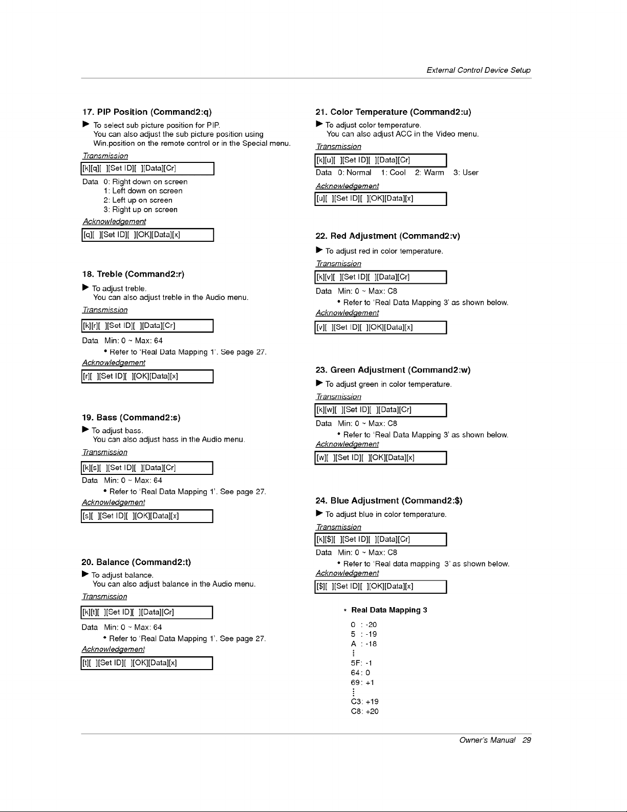
17. PIP Position (Command2:q)
I_ To select sub picture position for PIP.
You can also adjust the sub picture position using
Win.position on the remote control or in the Special menu.
Transmission
[[k][q][ ][Set ID][ ][Data][Cr] J
Data 0: Right down on screen
1 : Left down on screen
2: Left up on screen
3: Right up on screen
Acknowledqement
I[q] [ ][Set ID][ ][OK][Data][x] ]
18. Treble (Command2:r)
I_ To adjust treble.
You can also adjust treble in the Audio menu.
Transmission
[[k][r][ ][Set ID][ ][Data][Cr] I
Data Min: 0 ~ Max: 64
• Refer to 'Real Data Mapping 1'. See page 27.
Acknowledgement
[[r][ ][Set ID][ ][OK][Data][x] I
19. Bass (Command2:s)
I_ To adjust bass.
You can also adjust hass in the Audio menu.
Transmission
[[k][s][ ][Set Ig][ ][gata][Cr] ]
Data Min: 0 - Max: 64
• Refer to 'Real Data Mapping 1'. See page 27.
Acknowledgement
[[s][ ][Set ID][ ][OK][Data][x] ]
20. Balance (Command2:t)
I_ To adjust balance.
You can also adjust balance in the Audio menu.
Transmission
[[k][t][ ][Set ID][ ][Data][Cr] J
Data Min: 0 - Max: 64
• Refer to 'Real Data Mapping 1'. See page 27.
Acknowledgement
[[t][ ][Set ID][ ][OK][Data][x] J
21. Color Temperature (Command2:u)
I_ To adjust color temperature.
You can also adjust ACC in the Video menu.
Transmission
[[k][u][ ][Set ID][ ][Data][Cr] ]
Data 0: Normal 1: Cool 2: Warm 3: User
Acknowledgement
[[u][ ][Set ID][ ][OK][Data][x] J
22. Red Adjustment (Command2:v)
I_ To adjust red in color temperature.
Transmission
[[k][v][ ][Set ID][ ][Data][Cr] J
Data Min: 0 - Max: C8
• Refer to 'Real Data Mapping 3' as shown below.
Acknowledqement
[[v][ ][Set ID][ ][OK][Data][x] J
23. Green Adjustment (Command2:w)
I_ To adjust green in color temperature.
Transmission
[[k][w][ ][Set ID][ ][Data][Cr] ]
Data Min: 0 ~ Max: C8
• Refer to 'Real Data Mapping 3' as shown below.
Acknowledgement
[[w][ ][Set ID][ ][OK][Data][x] ]
24. Blue Adjustment (Command2:$)
I_ To adjust blue in color temperature.
Transmission
[[k][$][ ][Set ID][ ][Data][Cr] J
Data Min: 0 ~ Max: C8
• Refer to 'Real data mapping 3' as shown below.
Acknowledgement
[[$][ ][Set Ig][ ][OK][gata][x] J
* Real Data Mapping 3
0 :-20
5 :-19
A :-18
5F: -1
64:0
69 : +1
C3:+19
C8:+20
Owner's Manua! 29
ExternalControlDeviceSetup
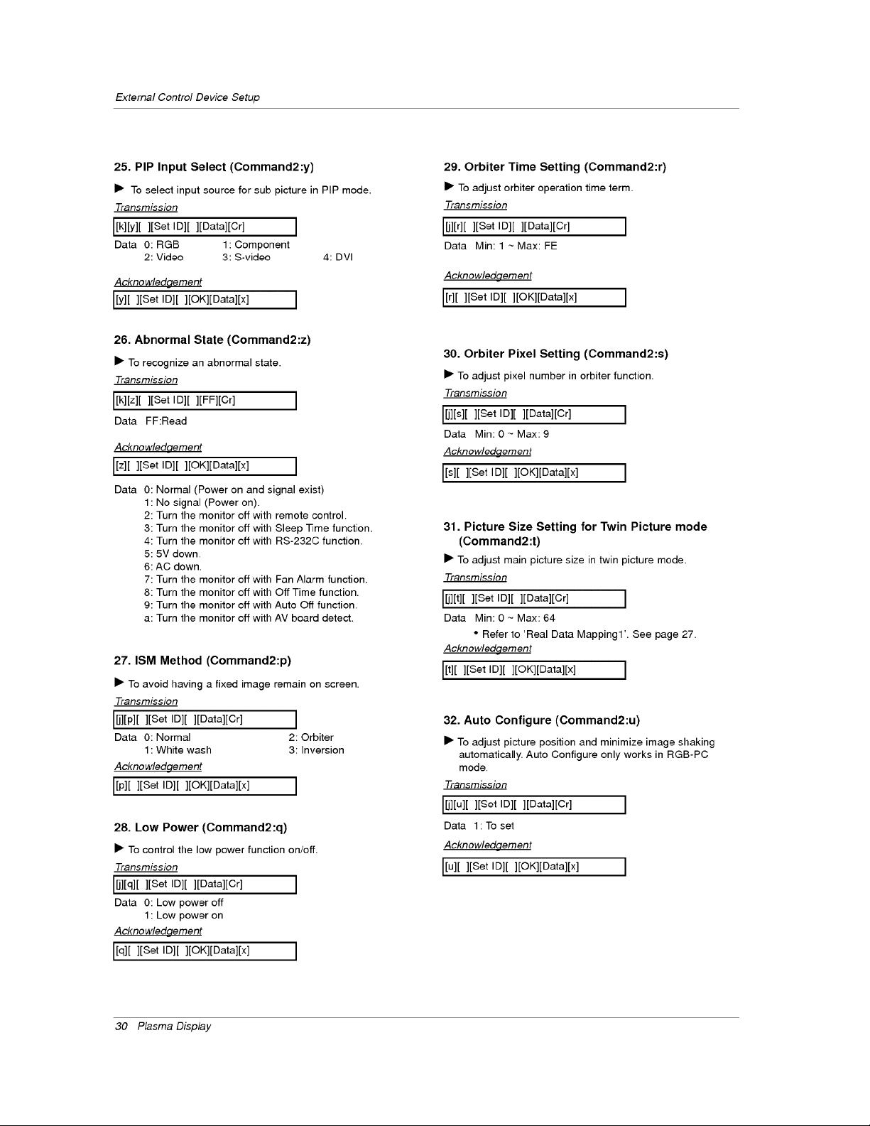
25. PIP Input Select (Command2:y)
• To select input source for sub picture in PIP mode.
Transmission
I[k][y][ ][Set ID][ ][Data][Cr] I
Data 0: RGB 1 Component
2: Video 3: S-video 4: DVl
Acknowledgement
I[y][ ][Set ID][ ][OK][Data][x] I
26. Abnormal State (Command2:z)
• To recognize an abnormal state.
Transmission
I[k][z][ ][Set ID][ ][FF][Cr] I
Data FF:Read
Acknowledaement
I[z][ ][Set ID][ ][OK][Data][x]
Data 0:
1:
2:
3:
4:
5:
6:
7:
8:
9:
a:
I
Normal (Power on and signal exist)
No signal (Power on).
Turn the monitor off with remote control.
Turn the monitor off with Sleep Time function.
Turn the monitor off with RS-232C function.
5V down.
AC down.
Turn the monitor off with Fan Alarm function.
Turn the monitor off with Off Time function.
Turn the monitor off with Auto Off function.
Turn the monitor off with AV board detect.
27. ISM Method (Command2:p)
• To avoid having a fixed image remain on screen.
Transmission
[[jl[p][ l[Set ID][ l[Datal[Cr] ]
Data 0: Normal 2: Orbiter
1: White wash 3: Inversion
Acknowledgement
I[p] [ ][Set ID][ ][OK][Data][x] I
28. Low Power (Command2:q)
• To control the low power function on/off.
Transmission
_][q][ ][Set ID][ ][gata][Cr] I
Data O: Low power off
1: Low power on
Acknowledgement
I[q] [ ][Set ID][ ][OK][gata][x] I
30 P_sma D_p_y
29. Orbiter Time Setting (Command2:r)
• To adjust orbiter operation time term.
Transmission
_][r][ ][Set ID][ ][Data][Cr] ]
Data Min: 1 ~ Max: FE
Acknowledgement
[[r][ ][Set ID][ ][OK][Data][x]
30. Orbiter Pixel Setting (Command2:s)
• To adjust pixel number in orbiter function.
Transmission
_][s][ ][Set ID][ ][Datal[Cr ] ]
Data Min:0~Max:g
Acknowledgement
[[s][ ][Set ID][ ][OK][Data][x] ]
31. Picture Size Setting for Twin Picture mode
(Command2:t)
• To adjust main picture size in twin picture mode.
Transmission
L_l[t][ ][Set ID][ ][Datal[Cr] ]
Data Min: 0 ~ Max: 64
• Refer to 'Real Data Mapping1'. See page 27.
Acknowledgement
[[t][ ][Set ID][ ][OK][Data][x] ]
32. Auto Configure (Command2:u)
• To adjust picture position and minimize image shaking
automatically. Auto Configure only works in RGB-PC
mode.
Transmission
_][u][ ][Set ID][ ][Data][Cr] ]
Data 1 To set
Acknowledgement
[[u][ ][Set ID][ ][OK][Data][x] ]
IR Code Information
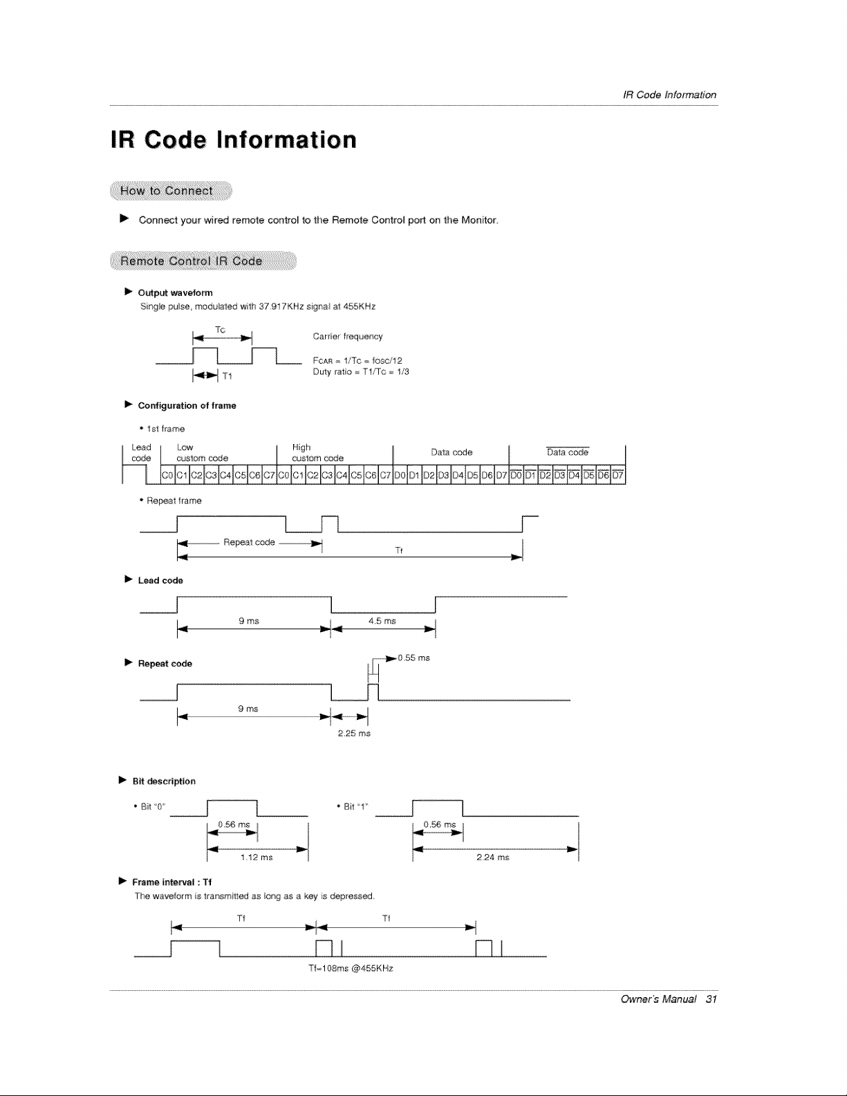
IR Code Information
I_ Connect your wired remote contro_ to the Remote Control port on the Monitor
I_ o_put wavefotm
Sitr'lgle pulse, modu_a'[ed with 37 917KHz signal at 455KHz
TO
Carrier f_equer_cy
_____J--l__ FOAF_= l/To = _osc./12
Duly ratio = T1/Tc = 1/3
I_ Configuration of frame
1Sit frame
I Lead Low Hgh Dma c_e
_? IC21C31C4t051C61C71C010! IC21C31G41C51C61CTIF)OIDt 1©2 ID3 ID41D51D61 D7 I*@_l_l_ I_ _l_l_l_l
" Re_,al frame
__J l___
Rer_el code
II_ Lead code
__1 I
I 9ms _i_
4,5 ms
Repe_ code
9 ms
Tf
J
2,25 ms
I_ Bit _c_iptfon
• Bit 1"
2,24 ms
i_ Frame in.Peal : Tf
The waveform }s trartsmilled as io_g as a key s depress_J,
Tf Tf
__[_1 D I D I
Tf=108ms @455KHz
Owner_ Manual 31
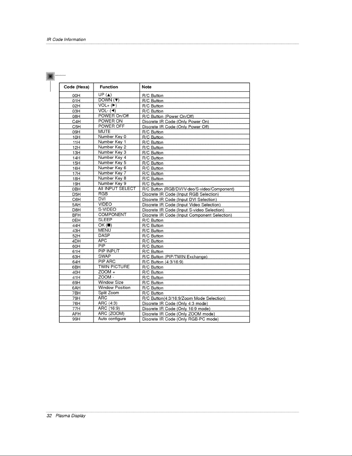
IR Code Information
00H UP (A) R!C Button
0! N DoWN (v) Bt¢Bu_on
02H VOL+ (1_) R/C Button
03H VOL" (_) R/C Bu_#n
C4H POWER ON Discrete !R Code (On!y Bower On)
C5H POWER OFF Discrete IR Code (On!y Power Off)
09H MUTE R/C Button
10H N#mber Key 0 R/C Button
i2H Number Key 2 PJC Button
!#N NumberKe_3 R/CBu_£n
i4H Number Key 4 R/C Button
i5H Number Key 5 R/C Button
16H Number Key 6 R/C Button
i 7H _ Numbe r Ke)/7 _ RiC Bul_ton
18H Number Key 8 R!C Button
19H Number Key 9 R!C Button
0BH Al! !NPU T SELECT R!C ButtOn (RGB!DV!!Vtd÷o/STv!deo!Compone_)
D5H RGB Discrete IR Code (Input RGB Select:ion)
G6H DV! D!s_eSe !R C0de (!n#ut #Y! #eie_ipo)
0EH SLEEP R/C Button
44H OK (I) PJC Button
43H MENU R/C Button
52H DASP P#C Button
4DH APC R/C Button
60H PIP R/C Button
61H PIP INPUT R/C Button
63H SWAP RiG Button (P!P/TWIN Exchange}
6BH TWIN PICTURE R/C Button
.............45_q:...............Zb@:_............................P_(_But{0n
41H ZOOM - R/C Button
69H Window Size R/C Button
6AH Window Position R/C Button
7BH Split Zoom R/C Button
79H ARC R/C Button(4:3,i6:9/Zoom Mode _lectien)
76H ARC (4_3) Discrete IR Code (Only 4:3 mode)
77H ARC (16:9) Discrete tR Code (On!y 16:9 m#de}
99H Auto configure Discrete IR Code (Only RGB°PC mode)
32 P_sma D_p_y
Troubleshoo#ng Checklist
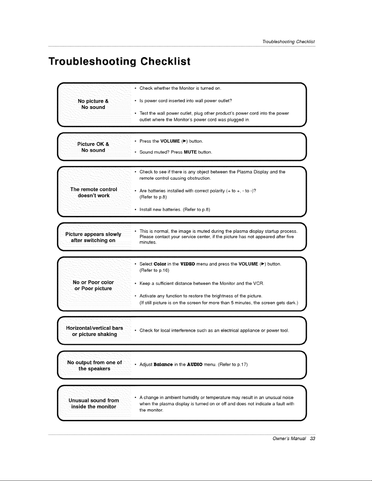
Troubleshooting Checklist
_i__ii_i__i_ii!i_i_!i_ii_ii_iiiiii_!___'i! _i!_"OheokwhethorthoMon_tor,otum_oo,
i_ ! i i i
NO picture& _spower cord inserted into waii power outlet?
NO sou.d • Test the waii power outlet plug other produd's power cord ,nto the power
outlet where tl_e MonitoCs power cord was plugged in_
Picture OK &"
L sou,d.
Press the VOLUME (1% button.
Sound muted? Press MUTE button
. Check to see if there is _y object _tween the Plasma Display and the
remote control causing obstruction,
The _mote control , Are batteries inst_led with correct potadty (+ to ÷ -to -)?
doesn t work (Refer to p 8)
* Select Color in the VID]IEO menu and press the VOLUME (1_) bu_on.
(Refer to p i6}
No or Poor comor. Keep a sufficient disl_ce between the Monitor and the VCR.
* Activate any function to restore the brightness of tile picture.
(if stilt picture is on the screen for more than 5 mh_utes, tile screen gets dark.)
Check for Iocai interference such as an eQectricai appliance or power tool,
r-No output from one of, Adjust 8_¢e in the A_,O menu. (Refer to p.17)
J
the speake[s
L °°°°"°'°°°°°_°_ ° J
_..2_._ ;k2 _..L_./.. when the pta_ma display is turned on or off and does no_ indicate a fau_t with /
.._,u_ ,._ .....,,u, the monitor
Owner_ Manual 33
Maintenance&Specification
Early malfunctions can be prevented. Careful and regular cleaning can extend the amount of time you witl have your
new Monitor. Be sure to turn the power off and unplug the power cord before you begin any cleaning.
1. Here's a great way to keep the dust off your screen for a while Wet a so_ cloth in a mixture of _ukewarm water and
a little fabric softener or dish washing detergent Wring the cloth until its almost dry, and then use it to wipe the
screen,
2, Make sure the excess water is off the screen and then tet it air-dry before you turn on your Monitor,
To remove dirt or dust, wipe the cabinet wittl a soft, dry, [i_-free cloth
Please be sure not to use a wet cloth.
If you expe_ to leave your Monitor dormant for a long time (such _ a vac_ion), it's a good idea to
unplug the power cord to protect against possible damage from _ightning or power surges.
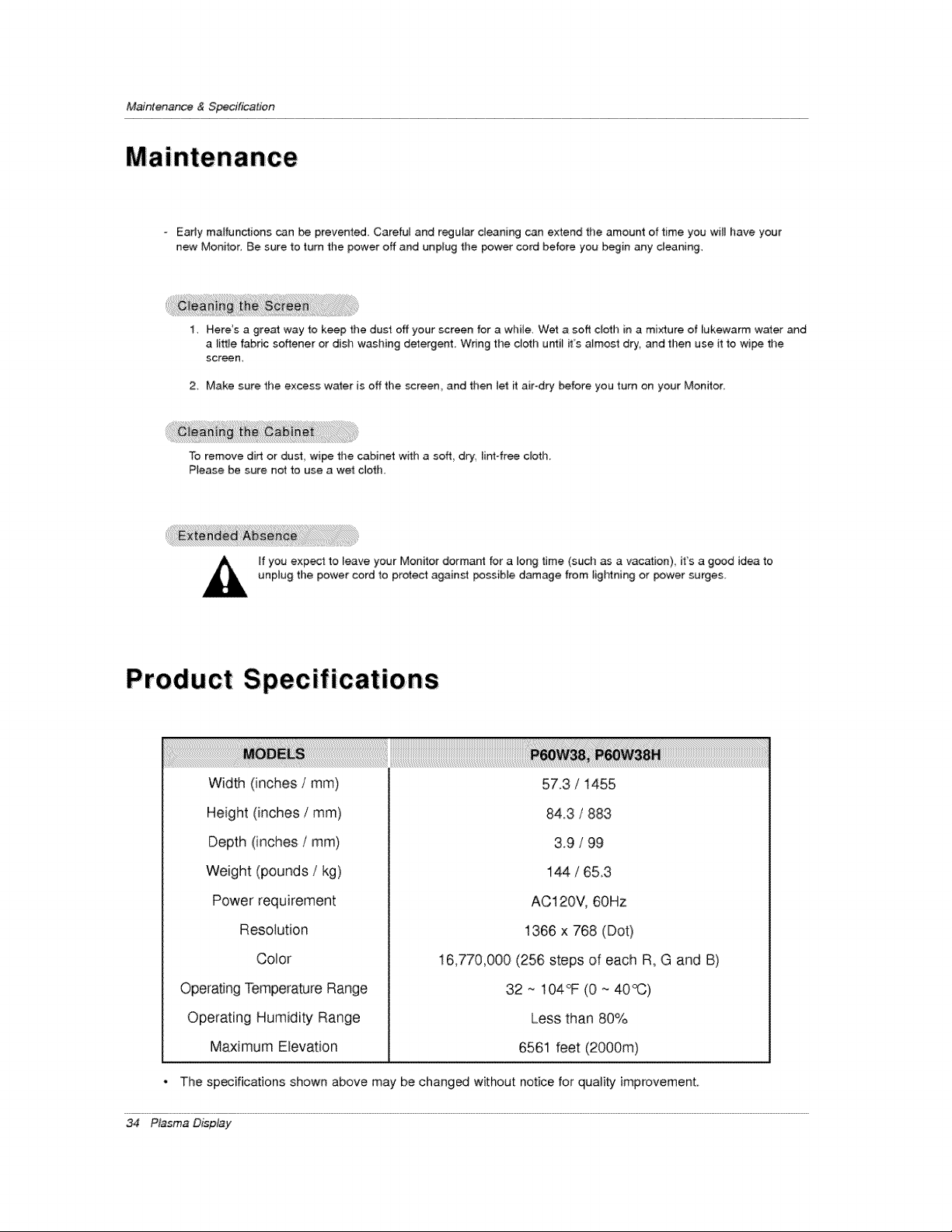
Prod uc t:S pec if icat io ns
Width (inches/ram)
Height (inches / mm)
Depth (inches/ram)
Weight (pounds / kg)
Power requirement
Resolution
57.3 / 1455
84.3 / 883
3.9 / 99
144 / 65,3
AC120V, 60Hz
1366 x 768 (Dot)
Color
Operating Temperature Range
Operating Humidity Range
Maximum Elevation
16,770,000 (256 steps of each R, G and B)
32 ~ 104°F (0 ~ 40°(3)
Less than 80%
6561 feet (2000m)
The specifications shown above may be changed without notice for quality improvement
34 P_sma D_p_y
Zenith will repair or replace your product, at Zenith's option, if it proves to be defective in material or workman-
ship under normal use, during the warranty period ("Warranty Period") listed below, effective from the date of orig-
inal consumer/end user purchase. This warranty is good only to the original consumer/end user of the product and
is effective only when used in the United States.
WARRANTY PERIOD:
LABOR: ONE YEAR from the Date of Purchase.
PARTS: ONE YEAR from the Date of Purchase.
Effective Date of Warranty: Your warranty period
Begins on the date of sale to the original
consumer/end user. KEEP THE DEALER'S DATED BILL
OF SALE OR PROOF OF DELIVERY as evidence of the
purchase date. You will be required to submit a legible
copy of your bill of sale or proof of delivery when
requesting warranty service.
Repair Parts and Replacement Units are warranted
for the remaining period of the original warranty.
HOW SERVICE IS HANDLED:
In Home Service. Please Call the Zenith Interactive
Center at 1-877-9ZENITH (1-877-993-6484) to
schedule a service appointment.
Your unit will be repaired or replaced with a new, sub-
stitute model or factory reconditioned unit, at Zenith's
option. If repaired, parts used in the repair may be new
or remanufactured.
Visit our website at http://www.zenithservice.com
THIS WARRANTY IS IN LIEU OF ANY OTHER WARRANTIES, EXPRESS OR IMPLIED, INCLUDING WITHOUT
LIMITATION, ANY WARRANTY OF MERCHANTABILITY OR FITNESS FOR A PARTICULAR PURPOSE. TO THE
EXTENT ANY IMPLIED WARRANTY IS REQUIRED BY LAW, IT IS LIMITED IN DURATION TO THE EXPRESS
WARRANTY PERIOD ABOVE. ZENITH WILL NOT BE LIABLE FOR ANY INCIDENTAL, CONSEQUENTIAL,
INDIRECT, SPECIAL, OR PUNITIVE DAMAGES OF ANY NATURE, INCLUDING, WITHOUT LIMITATION, LOST
PROFITS, LOST OR CORRUPTED PROGRAMMING OR DATA, OR ANY OTHER DAMAGE WHETHER BASED IN
CONTRACT, TORT, OR OTHERWISE. Some states do not allow the exclusion or limitation of incidental or conse-
quential damages or limitations on how long an implied warranty lasts, so the above exclusion or limitation may not
apply to you. This warranty gives you specific legal rights and you may also have other rights that vary from stat
to state.
THIS LIMITED WARRANTY DOES NOT APPLY TO:
• damage caused in shipping or transit
• service required as a result of improper installation,
including incorrect or insufficient AC supply (please
consult the owner's manual for power supply
requirements)
• installation or repair of antenna systems, cable con-
verters, cable company supplied equipment, or
other components in a video system
• set-up or adjustment on consumer controls, or
damage caused by improper adjustments
• damage caused by other system components
• any panel that has been modified or incorporated
into any other product
• replacement of batteries on the remote control.
• damage (including cosmetic damage), failure, loss
or personal injury due to misuse, abuse, negli-
gence, improper maintenance or storage, or to acts
of nature or other causes beyond Zenith's control.
(Causes beyond Zenith's control include but are not
limited to lightning strike, power surges, power out-
ages and water damage.)
• Image burn-in
• repair or replacement of warranted parts by other
than Zenith Authorized Service Centers.
• units purchased or serviced outside of the U.S.A.
• product where the original factory serial numbers
have been removed, defaced or changed in any
way.
• product sold and labeled as "as is, where is" or sim-
ilar disclaimer.
The costs of repair or replacement under these excluded circumstances shall be borne by the consumer.
CONCERNING PIXEL FUNCTIONALITY: Your Plasma Display Panel contains about one million individual pixels.
Plasma displays typically contain a small number of pixels that do not function normally. Your display has been
inspected and is in compliance with manufacturer's specifications, indicating that any pixel defects do not affect the
operation or use of your display.
CUSTOMER INTER-ACTIVE CENTER NUMBERS:
To obtain customer assistance, prod-
uct information, or Dealer or Service
locations
Call 1-877-gZenith (1-877-993-6484) (24 hours a day,
365 days per year) and select appropriate options from the
menu.
Or visit our website at http://www,zenithservice,com
BEFORECALLINGFORSERVICE:
• Please check your operating guide - you may avoid a service call.
• Please have your product model number, serial number and the date of purchase or the date of original instal-
lation available.
• if a replacement unit is required, under some circumstances you may be asked to provide a reserve deposit to
Zenith against a credit card number as surety for advanced shipment. Your credit card will not be charged if
you return the defective unit within 10 working days.
• ]fa replacement unit is received, please use the carton and packaging from that unit in returning the defective
unit to Zenith.
• Parts and service in accordance with the Zenith warranty are Zenith's responsibility and will be provided without
charge. Other service requirements will be at tile owner's expense. If you have problems in obtaining satisfac-
tory warranty service, write or call the Zenith Customer Interactive Center. Service may be provided by inde-
pendently owned and operated service organizations.
• To assure proper credit and avoid unnecessary charges, you must obtain a Return Authorization before return-
ing any product for Zenith Warranty Service. Contact the number below or your authorized Zenith repair facility
for details.
IMPORTANT: Please fill out and mail your Product Registration Card or go to www.zenithservice.com to register
your product online. This information allows Zenith to reach you promptly should we discover a safety or reliabili-
ty problem that could affect you.
TO CONTACT ZENITH BY MAIL:
Zenith Customer Interactive Center
P.O. Box 240007
201 James Record Road
Huntsville, AL 35824
A-i-I-N: CiC Plasma Display, Building 3
P/N ' 3828VA0400G @ (R F03LA) 206-3917

