
zonith
P{ease read this operating guide carefully before
usfng the Mon{tor.
Keep the operating gufde with the Monitor, _t;" _
For future reference, wdte down the serial number
on the back of the Monitor in the space provided
below.
Model number :
Seria_ number :
P/NO : 3828VAO277V
(NPOOKB)
206-03784
Table of Co
First step
WARNENGS 4
SAFETY INSTRUCTIONS ................................... 5
Monitor Overview
Front Panel Controls ......................................... 8
Connection Panel Overview ..................................... 9
Remote Control Key Functions/Accessories ..........10
Monitor Installation ................................................. 12
Equipment Connections and Setup
VCR Setup .............................................................. 14
Cable TV Setup ....................................... 16
External AV Source Setup ........................................17
DVD Setup ................................................................ 18
DTV Setup ........................................................... 19
PC Setup .................................................................. 20
PC Mode Feature Check(Overview) ...................... 22
PC Mode Adjustments ............................................ 23
Picture In Picture (PIP) function ............................. 26
Twin picture function ............................................... 29
Using the remote control ........................................ 31
Basic Features Setup and Operation
Turning on the Monitor ..................................... 32
Selecting Menu Language ................................... 33
Checking features ................................................... 34
Sl_p Timer
Setting Sleep Timer (Monitor turn-off time) .......... 35
Picture & Sound
Auto picture control ................................................ 36
Adjusting picture appearance ................................. 37
DRP (Digital Reality Picture) .................................. 38
Adjusting Sound: Bass, Treble, Balance ................39
Auto Sound Control ..................................................40
AVL (Auto volume leveler) ....................................... 41
S_cial Features
Using Still function ............................................. 42
Using the Screen Menu Options ............................. 43
Adjusting Menu Transparency ................................ 44
Adjusting color temperature ................................... 45
Setting picture format ............................................. 46
External control device setup ................................. 47
Others
Maintenance .................................................... 57
Troubleshooting checklist ...................................... 58
Product specifications .............................................. 59
WARNING:
TO REDUCE THE RISK OF ELECTRFC SHOCK DO NOT REMOVE COVER
IOR BACK), NO USER SERVICEABLE PARTS iNSIDE°
REFER TO QUALIFIED SERVICE PERSONNEL
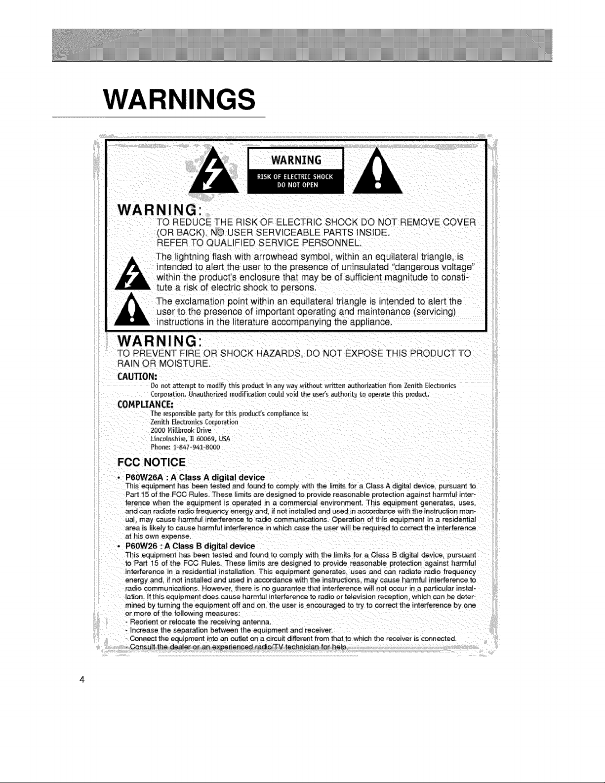
The lightning flash with arrowhead symbol, within an equilateral triangle, is
ntended to a_ertthe user to the presence of uninsulated "dangerous voltage"
within the product's enclosure that may be of sufficient magnitude to consti-
tute a risk of electric shock to persons.
nstructions in the literature accompanying the appliance
WARNING"
TO PREVENT F_RE OR .SHOCK HAZARDS, DO NOT EXPOSE THIS PRODUCTTO
RAIN OR MOISTURE.
CAUTION:
Do not attempt to modify this product in any w,_y without written authorization from Zenith Electronics
£e_£orat_on. U_uthodzed modification could voN the use(s authority to operate this predu_.
COMPLIANCE:
T}_ resoo_b_e patty _;e_U_s p_oduct's cempI_nce _s:
Zenith E1_m[fics [orpe_atien
20_ NiAbrook Drive
Uncotashire..[[ _69, USA
Phorm: 1.,847 94_o8(_
FCC NOTICE
• P6OW26A : A Class A digital device
This equipme_ has been test_ and found to comply with the limitsfor a C_assA digita_ device, pu_uant to
Part 15 of the FCC Ru_es. Those _imits are designed to provide reasonabJe protection against harmful inter-
uaL may cause harmful interference to radio communic_ions, Operation of this equipment in a residenlia_
area is likely to cause harmful interference in which case the user will be required to correct the interference
h_s own expense.
P6OW26 '. A Class B digital device
This equipment has been tested _d found "to comply wmtl_the limit_ for _ CIass B digifa_ devlce_ pursuant
radio communications. However there _sno guara_ee that interference wil_ not occur in a particular instate
_ation. If this equipment does cause harmfu_ interference to radio or television reception, which can be deter-
mined by turning the equipment off and on, the _se_ is encouraged to try to correct the irr_e#erence by one
or more of the following measures:
- Connect the equipme_ into an ouUet on a circuit different from th_ to which the receiver i= connected.
Consult the dee e[ o_ an exl#eder_c_ radie/3-M technician for he_p,
4

SAFETY I UCTIONS
Impor_nt safeguards for you and your new product
Your product has been manufactured and tested with your safety in mind. However, _mproper
points when installing and using your new product,and save them for future reference.
Observing the simple precautions discussed in this booklet can hetp you get many years of
enjoyment and safe operation that are built into your new product.
This product complies with all app icable U.S, Federal safety recquirements, and those of the
Canadian Stanaards Association
1. Read Instructions
AHthe safety and operating instructions
should be read before the product is operat-
ed.
2. Follow Instructions
slide or fall, causing serious injury to a child
or adult, and serious damage to the product,
Use only with a cart, stand, tr Ipod, bracket.
or table recommended by the manufacturer,
or sold with the product. Any mounting of
the product should follow the manufacturer's
instruction& and Should use a mounting
All operating and use instructions shouJdbe accessory recommended by the manufac-
followed, turer.
3. Retain Instructions
The safety and operating instructionsshould
be retained for future reference.
AHwarnings on the product and in the oper-
ati ng instructions shouadbe adhered to.
8. Transporting Product
A product and cart combination should be
moved with care. Quick stops, excessive
force, and uneven surfaces may cause the
product and cart combination to overturn.
......iii
ii! iiii!!!iiiiiiiiiii!i!ii!ii!ii!ii!ii!ii!ii!iii!i!iiii!iii!i!i!!:!
iiiiiii_l!i_i_i_i_i_i_i_i_i!!i!!i!!i!!i!i!i!ii!i!!!!!!!!!!!!!i:_:iiii
iiiii_iiiiiiii!i!iiiiiiii_ii!i!!!!!_i,i!ii%i_iii_ii!ili!iiii!_!ii_i:
iiiii_ii_i_::_::_::_::_::_::_:_i_!i_!i_!i_!i_!i_!i_!i_!i_!i_!i_!i_i!:i!_ii:!i:ii:ii:i!:_ii
iiiii_!;i;i;i_ii:i:i_i_i_i_i_i_i_i_:i!i!!i!!i!!i!!i!!i!!_!!!_ijii_iiiiii
i'i_ili!_ ii
Unplug this product from the wall outlet
before clean ng. DO not use liquid cleaners
or aerosol cleaners. Use a damp cloth for
cleaning.
6. Water and Moisture
Do not use this product near water, for
example, near a bath tub, wash bowl, cause hazards.
kitchen sink, or laundry tub, in a wet base-
ment. or near a swimming pool.
9. Attachments
Oo not use attachments not recommended
by the product manufacturer as they may
SJots and open_ngs in the cabinet are pro-
7. Accessories Carts and Stands vided for ventilation and to ensure reliable
Do not place this product on a slippery or operation of the product and to protect it
tilted surface, or on an unstable cart, stand, from overheating, and these openings must
tripod, bracket, or table. The product may not be blocked or covered.
(Continued on next page
i
iiiiiiiiiiiiiiiiiiiiiiiiiiiiiiiiiiiiiiiiiiiiiiiiiiiii
SAFETY INSTRU
(Continued from previous page)
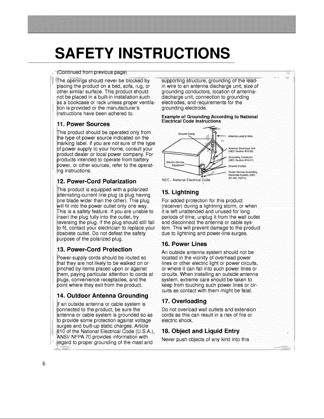
other similar surface. This product should grounding conductors, location of antenna-
lot be placed in a builtqn instaJlation such discharge umt. connection to grounding
_s a bookcase or rack unless proper venti4a- electrodes, and requirements for the
ion is provided or the manufacturer's grounding electrode.
nstructions have been adhered t&
11. Power Sources
his product should be operated only from Grand,amp
he type of power source indicatedon the / -.,. A_,_o_Jo_ro
marking }abel. If you are not sure of the type /
of power supply to your home, consuJt your ././ _%__°'_ _'
product dealer or local power company. For
products intended to operate from battery i_c_o,,_,_&_
power, or other sources, refer to the operat o _®_ c_.
ing instructions. --_'_--__ _ _:,',_,_,_,_s
Aq 2:5_ P_ H_
12. Power-Cord Polarization NEc N_o_,_oo_o_Code
it is left unattended and unused for long
periOdSOf time, unplug it from the wall outlet
eversing the plug. If the plug should still fail and disconnect the antenna or cable sys-
fit contact your electriciar_ to repJace your tern. This wilt prevent damage to the product
solete outteL Do not defeat the safety due to lightning and powerqine surge&
urpose of the polarized plug,
16. Power Lines
13. Power-Cord Protection
An outside antenna system should not be
cuits as contact with them might be fatal.
14. Outdoor Antenna Grounding
: an outside antenna or cable system is
onnected to the product, be sure the Do not overload wal_ outlets and extension
}ntenna or cable system is grounded so as cords as this can result in a risk of fire or
o provide some protection against voltage electric shock.
}urges and built*up static charges. Article
310of the National Electrical Code (U.S.A.), 18. Object and Liquid IEntry
_NSIi NFPA 70 provides information with Never push objects of any kind into this
egard to proper grounding of the mast and
product through openings as they may
touch dangerous voltage points or short-out
producL
product is in proper operating condition.
23. Wall or Ceiling Mounting
Do not attempt to service this product y0ur- The product should be mounted to a wal_ or
self as opening or removing covers may iiin
expose you to dangerous voltage or otfler ce g only as recommended by the manu-
• . _ .......... facturer The product may s de or fa, caus-
hazard& Refer aH servicing _o qua_meu ser- . . . _ .
_ng serious _njury to a ch_ d or adu t, and
vice personnel serious damage to the product.
20. Damage Requiring Service
Unplug this product from the wall outlet and
refer servicing to qualified service personnel
under the following conditions:
24. Heat
The product should be situated away from
heat sources such as radiators, heat regis-
ters, stoves, or other products (incbding
a. If the power-supply cord or plug is dam= amplifiers) that produce heat.
aged,
D_If liquid has been spilfed, or objects have
fallen into the product,
c If the product has been exposed to rain
or water.
d_ If the product does not operate normally
by following the operating instructions.
Adjust only those controls that are cov-
ered by the operating nstructions as an
improper adjustment of other controls
may result in damage and will often
....iii
i! iiii!!!iiiiiiiiiii!i!ii!ii!ii!ii!ii!ii!ii!iii!i!iiii!iii!i!i!!i!
iiiii_l!i_i_i_i_i_i_i_ii!!i!!i!!i!!i!i!i!ii!i!!!!!!!!!!!!!ii:iiii
iiiii_ii_i_i_!i_!i_!i_!i_!i_!i_!i_!i_!i_!i_!i_i!_i!_ii_!i_ii_ii_i!_ii
iiiii_!;i;i;i_iiii:i_i_i_i_i_i_i_i_ii!i!!i!!i!!i!!i!!i!!_!!!_ijii_iiiiii
ii_ili!_ ii
normal operation.
e_ If the product has been dropped or the
cabinet has been damaged.
f. If the product exhibits a distinct change
in performance.
21. Replacement Pa_s
When replacement pa_ts are required, be
sure the serwce technician has used
replacement parts specified by the manufac-
turer or have the same characteristics as
the original part. Unauthorized substitutions
may result in fire, electnc shock, or other
hazards.
7
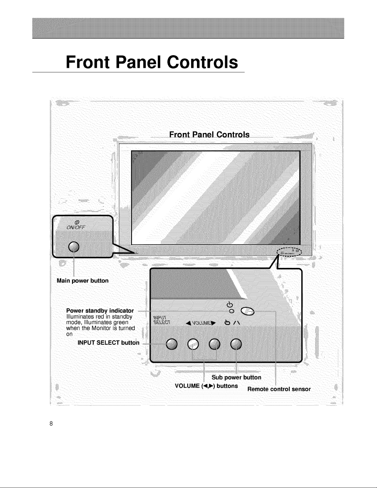
rols
Front Panel Controls
Power standby indicator
It uminates red in standby
moae, Illuminates green
when the Monitor is turned
OR
INPUT SELECT button
VOLUME (<1,1_)buttons Remote control sensor
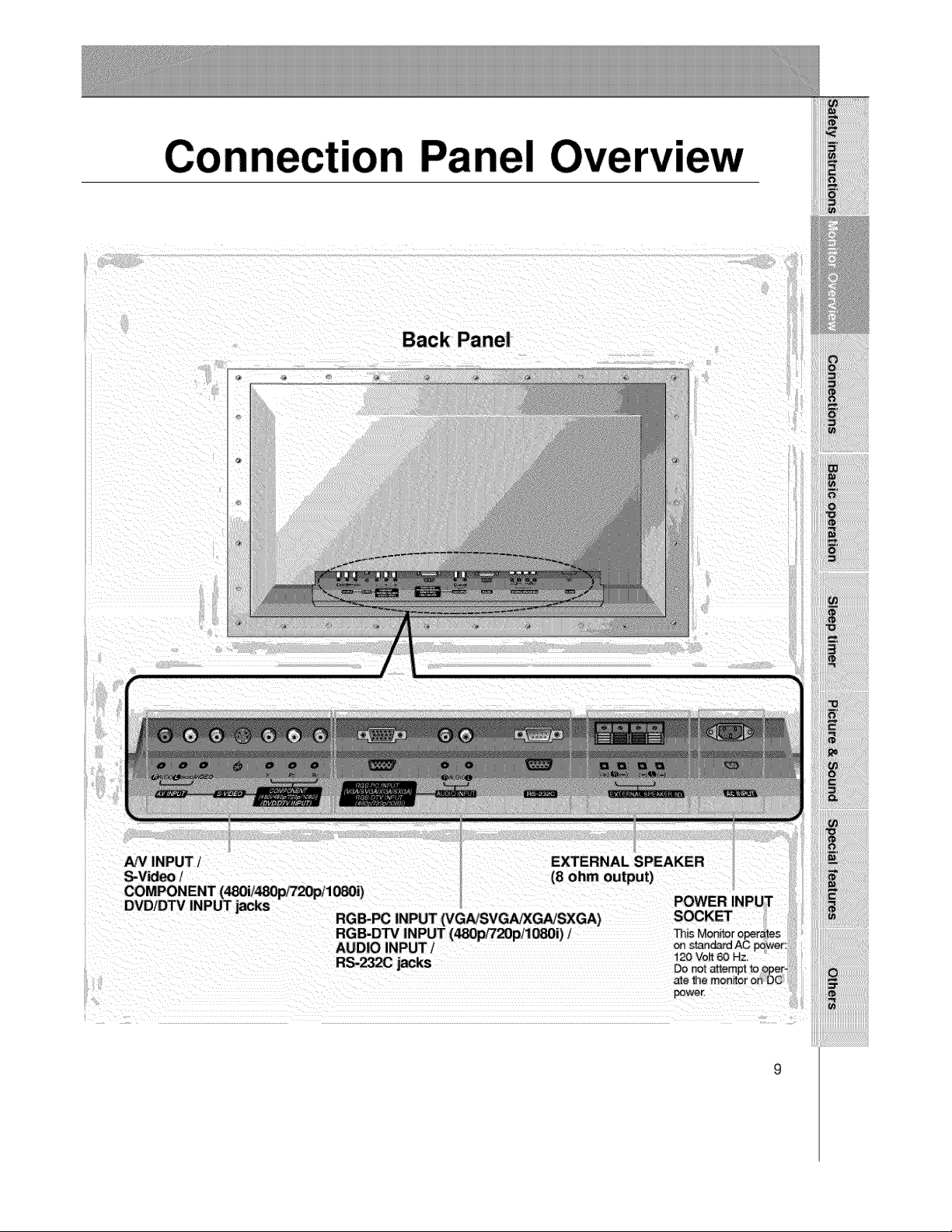
Con "on Panel
lew
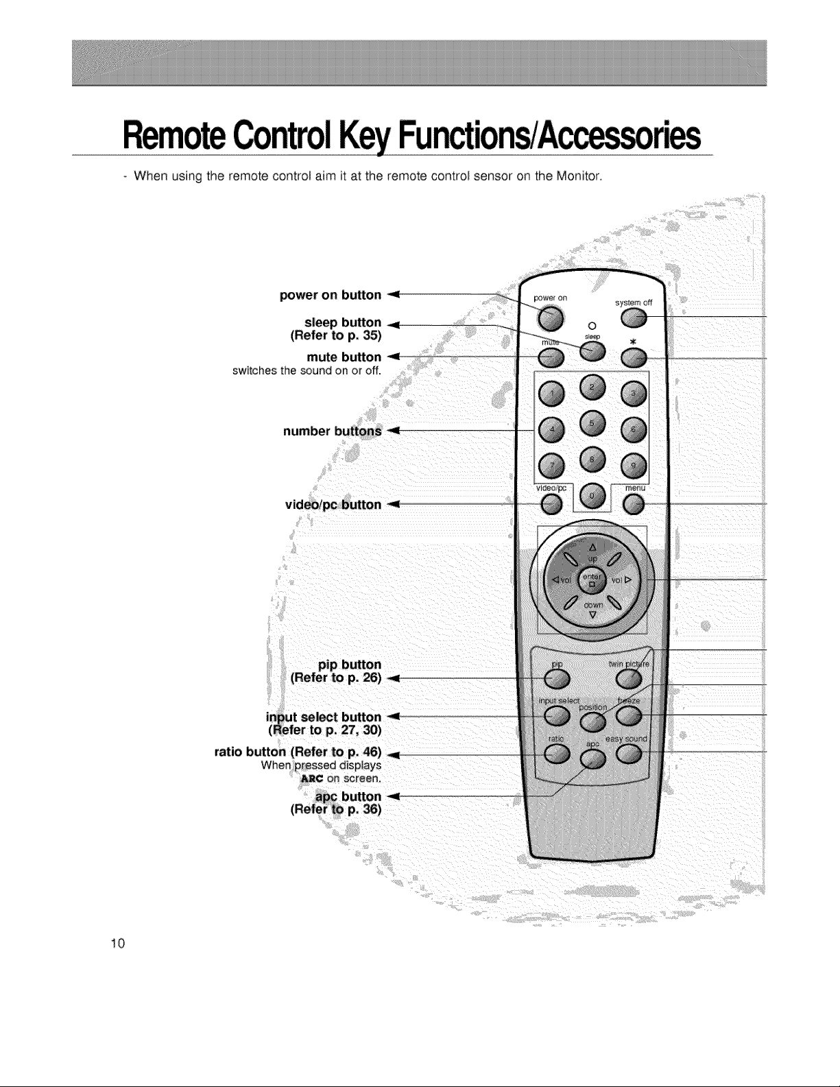
- When using the remote control: aim it at the remote control sensor on the Monitor.
power on button _,
mute button -<
switches t_e sound on or off.
number buttons
video/pc button -_
(Refer to p. 26) -._
ratio button (Refer to p. 46)
When pressed d_splays
_¢ on screen.
10
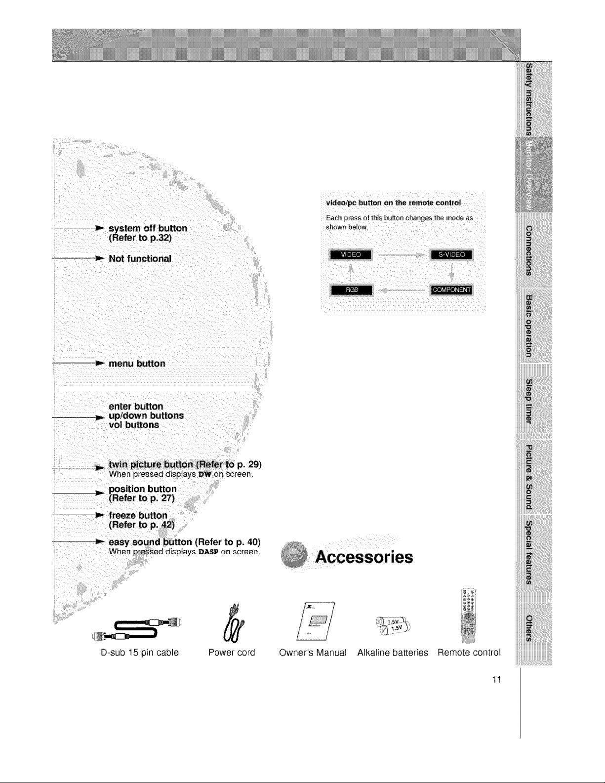
_-_system off button
o_m,- Not functional
iiiiiii!!!!!!!! !ii!i i !i !i !i !ii!ii!ii!ii ii!ii!ii!ii!ii!ii!ii!ii!ii i !i!i! !i!i! ! i iilili
ii_i_i_i_i_i_i_!_!_!_!_!_!_!_!_!_!_!_!_!_!_!_!_!!!!!!!!!!!!!!!!_!i_!i_!i_!_!!ii
:_m,-menu button
enter button
vol buttons
twin picture hUrOn (Refer to p. 29)
When pressed displays DWon screen.
position button
Y (Refer to p, 27)
freeze button
...._ easy sound button (Refer to p. 40)
When pressed disptays :D_P on screen.
D=sub 15 pin cable
Power cord Owner's Manual Alkaline batteries Remote control
11
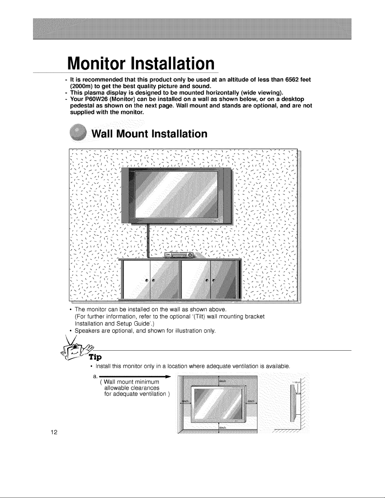
Monitor Installation
- It is recommended that this product only be used at an altitude of less than 6562 feet
(2_0m) to get the _st quality picture and sound+
- This plasma display is design_ to be mount_ horizontally (wide viewing).
+ Your P60W26 (Monitor) can be installed on a wall as shown below, or on a desktop
pedestal as shown on the next page+Wall mount and stands are optional, and are not
suppli_ with the monitor+
@ Wall Mount Installation
• The monitor can be installed on the walt as shown above.
(For further information, refer to the optional '(Tilt) wall mounting bracket
Installation and Setup Guide'+)
• Speakers are optional, and shown for iiiustration only.
12
• install this moni+toronly in a location where ad_uate ventilation is available.
( Wall mount minimum
allowable clearances
for adequate ventilation )
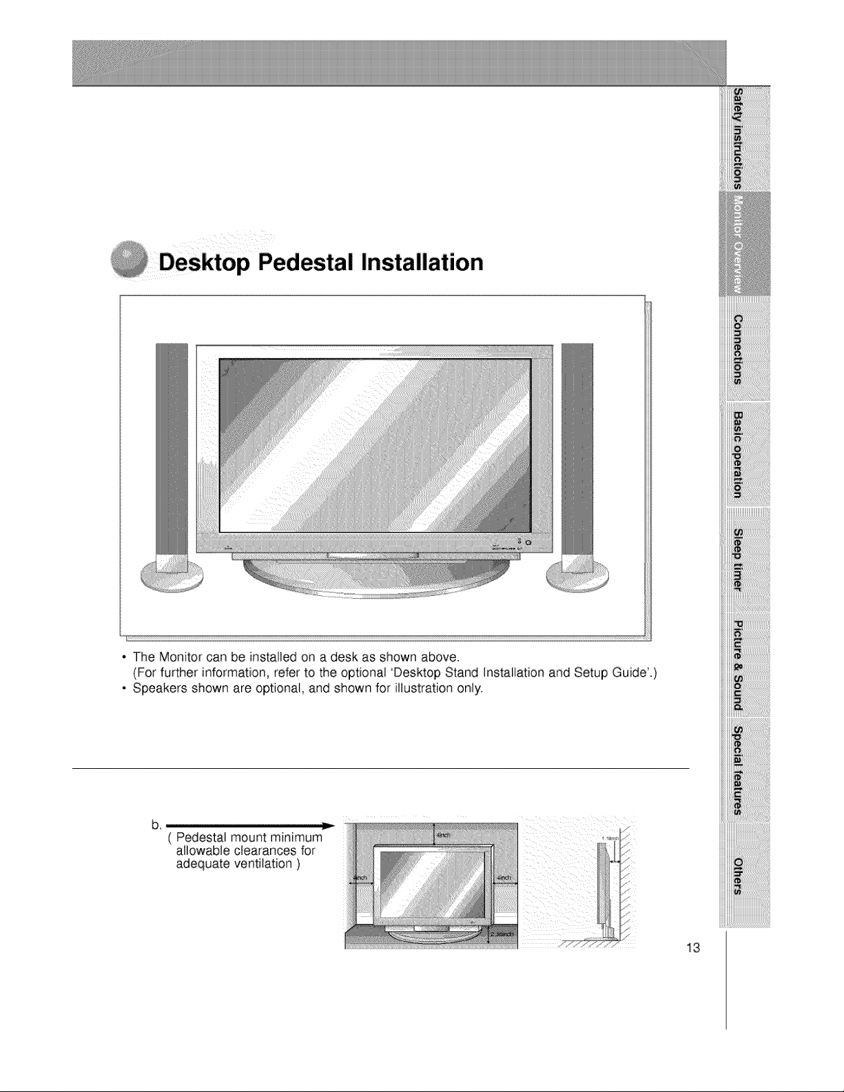
p Pedestal Installation
iiiiii_i!_i!_i_i_i_i_i_i_i_ii_ii_ii_ii_ii_ii_ii_i_i_i_i_!_i_!_i_i_!!!iiii
. The Monitor can be installed on a desk as shown above.
(For further information, refer to the optional 'Desktop Stand Installation and Setup Guide.)
. Speakers shown are optional, and shown for illustration only.
13
P
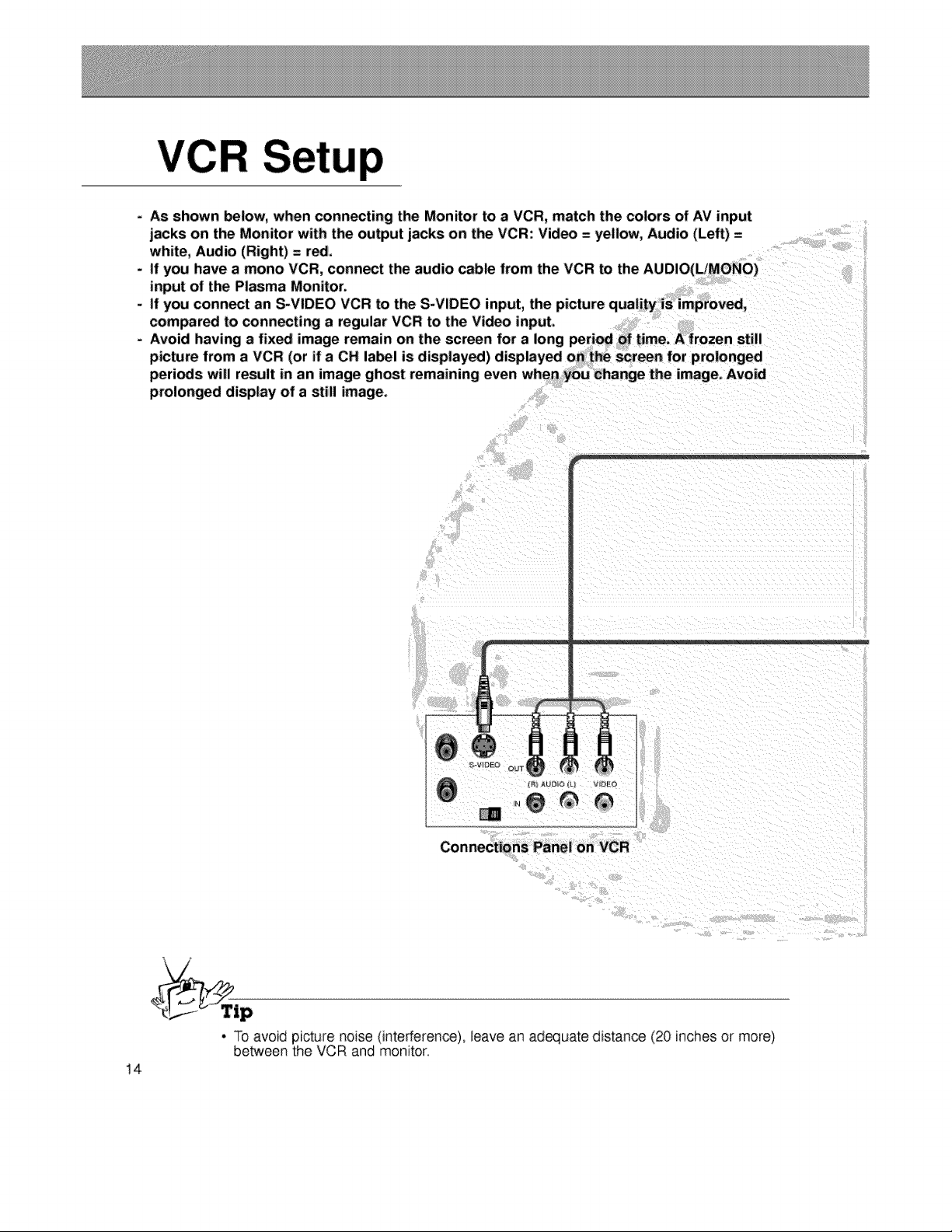
- As shown below, when connecting the Monitor to a VCR, match the colors of AV input
jacks on the Monitor with the output jacks on the VCR: Video = yellow, Audio (Left) =
white, Audio (Right) = red.
- If you have a mono VCR, connect the audio cable from the VCR to the AUDIO(L/MONO)
input of the Plasma Monitor.
if you connect an S-VIDEO VCR to the S-VIDEO input, the picture quality is improved,
compared to connecting a regular VCR to the Video input.
- Avoid having a fixed image remain on the screen for a long period of time. A frozen still
picture from a VCR (or if a CH label is displayed) displayed on the screen for prolonged
periods will result in an image ghost remaining even when you Change the image. Avoid
prolonged display of a still image.
Connections Panel on VCR
14
4
• To avoid picture noise (interference), leave an adequate distance (20 inches or more)
be_een the VCR and monitor
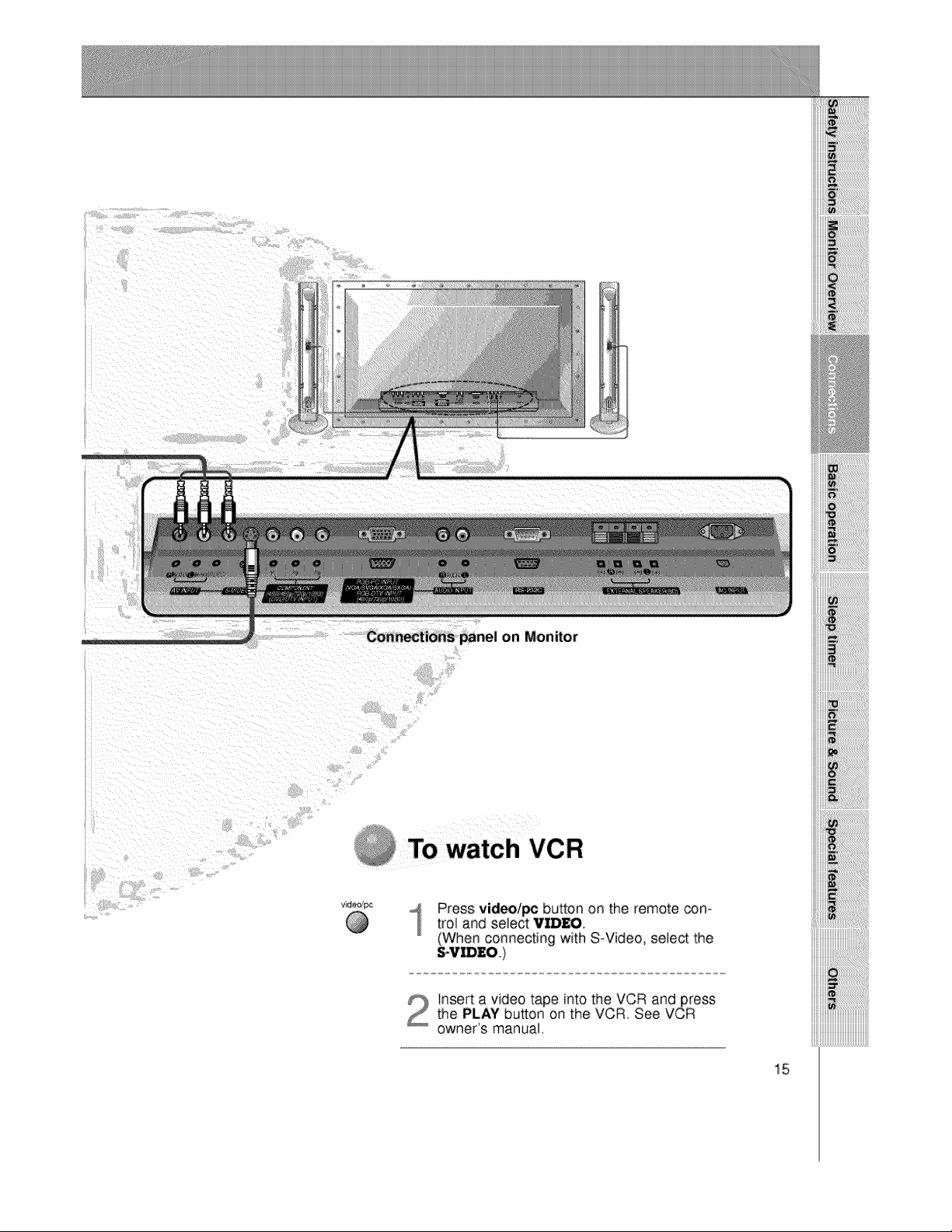
Connections panel on Monitor
iiiiiii_iiiiiiiii!iiiiiiiiiiiii_i_ii_ii_ii_ii_ii_ii_ii_ii_ilili!!!i_il
iiiiiii_i!i!i!i!i!i!i!i!i!i!i!i!i!i!il;iiiiiiiiiiiiiiiiiiiiiiii_i_!iiii
To watch VCR
Press video/_ button on the remote con-
trol and select VIDEO,
(When connecting with S_Video, select the
Insert a video tape into the VCR and press
the PLAY button on the VCR. See VCR
owner's manual,
15
e rv
p
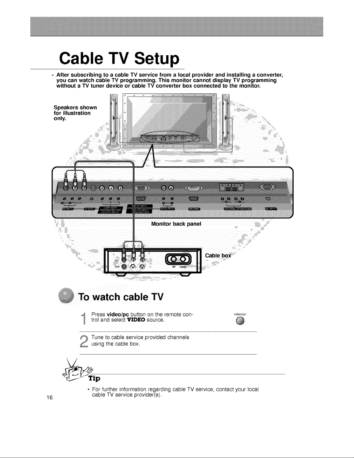
- After subscribing to a cable TV service from a local provider and installing a converter,
you can watch cable TV programming. This monitor cannot display TV programming
without a TV tuner device or cable TV converter box connect_ to the monitor.
for illustration
only.
Monitor back panel
Cable box
To watch cable TV
Press video/pc button on the remote con-
troi and select VIDEO source.
Tune to cable service provided channels
using the cable box
• For further information regarding cable TV service, contact your local
16 cable TV service provider(s)
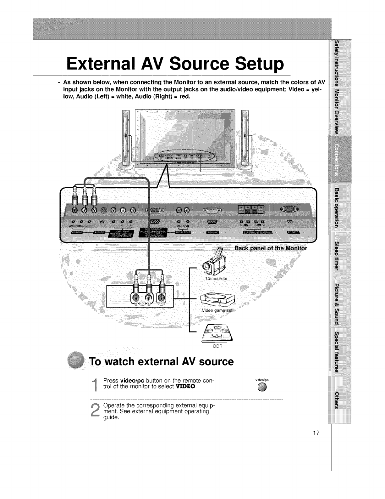
nal AV Source Setup
- As shown below, when connecting: the Monitor to an external source, match the colors of AV
input jacks on the Monitor with the output jacks on the audio/video equipment: Video = yel-
low, Audio (Left) = white, Audio (Right) = red,
Oamcorder
Back panel of the Monitor
Video game seTL
DDR
@ TO watch external AV source
Press video/pc button on the remote corn
trot of the monitor to select Vl]D£O.
video/pc
Operate the corresponding external equip-ment. See external equipment operating
guide.
iiiiii_uiiiiiiiiiiiiiiiiiiiiiiiiiiiiiiiiiiiiiiiiii_
iiiiii_uiiiiiiiiiiiiiiiiiiiiiiiiiiiiiiiiiiiiiiiiii_
iiiiii_uiiiiiiiiiiiiiiiiiiiiiiiiiiiiiiiiiiiiiiiiii_
iiiiii_uiiiiiiiiiiiiiiiiiiiiiiiiiiiiiiiiiiiiiiiiii_
iiiiii_uiiiiiiiiiiiiiiiiiiiiiiiiiiiiiiiiiiiiiiiiii_
iiiiii_uiiiiiiiiiiiiiiiiiiiiiiiiiiiiiiiiiiiiiiiiii_
iiiiii_uiiiiiiiiiiiiiiiiiiiiiiiiiiiiiiiiiiiiiiiiii_
17
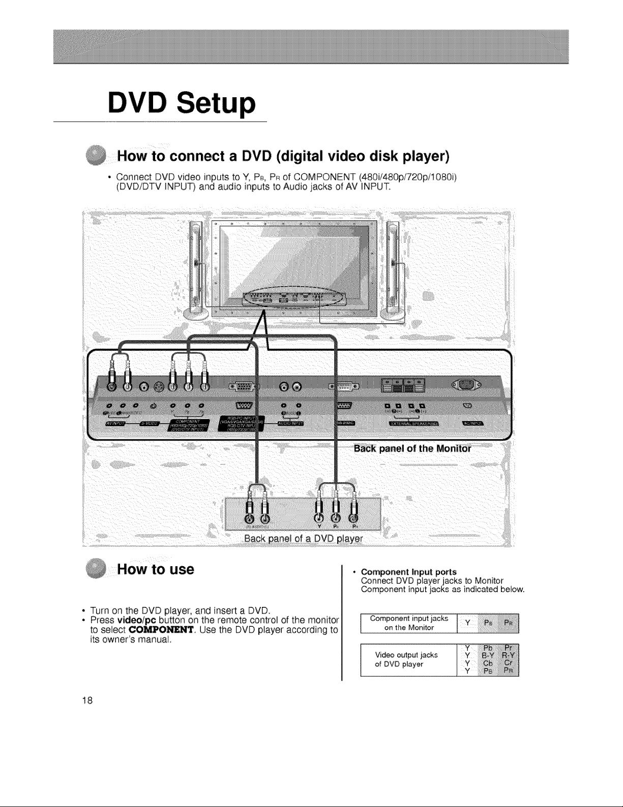
How to connect a DVD (digital video disk player)
• Connect DVD video inputs to Y, P_, PR of COMPONENT (480i/480p/720pi1080i)
(DVD/DTV INPUT)and audio inputs to Audio jacks of AV INPUT.
of a DVD
HOWt0 use
• Turn on the DVD player, and inserta DVD.
• Press video/pc button o.nthe remote control of the monitor
to select COMPO_. Use the DVD piayer according to
its owner's manual.
• Component Input ports
Connect DVD player jacks to Monitor
Component input jacks as indicated below.
Component input jacks
on the Monitor
Video output ._acks
of DVD player
18
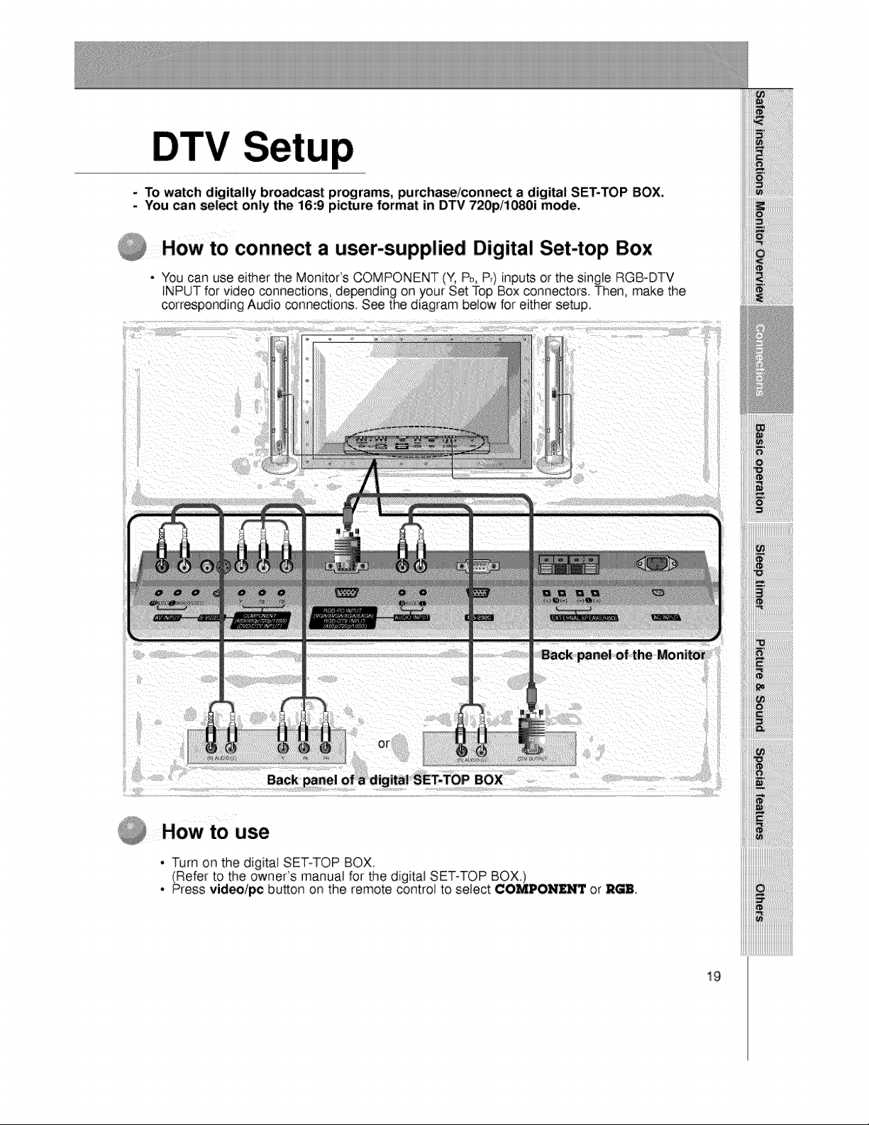
To watch digitally broadcast programs, purchase/connect a digital SET-TOP BOX.
- You _n select only the 16:9 picture format in DTV 720p/1080i m_;e.
How to connect a user-supplied Digital Set-top Box
• You can use either the MonitoCs COMPONENT (Y, Pb,P_)inputs or the single RGB-DTV
INPUT for video connections, depending on your Set Top Box connectors. Then, make the
corresponding Audio connections. See the diagram below for either setup.
Back
How to use
* Turn on the digital SET-TOP BOX.
(Refer to the owner's manual for the digital SET-TOP BOX.)
, Press videolpc button on the remote control to select ¢OMIDON_ or _H
iiiiii_iiiiiiiiiiiiiiiiiiiiiiiiiiiiiiiiiiiiiiiiiii_
19
up
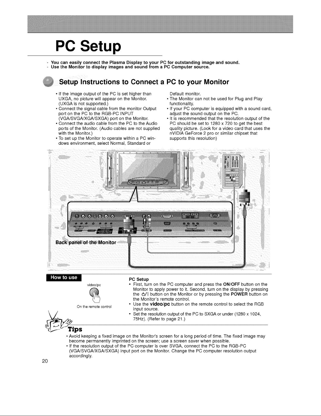
- You can easily connect the Plasma Display to your PC for outstanding image and sound.
Use the Monitor to display images and:sound from a PC Computer source.
Setup Instructions to Connect a PC to your Monitor
• If the image output of the PC is set higher than
UXGA, no picture will appear on the Monitor.
(UXGA is not supported.)
• Connect the signal cable from the monitor Output
port on the PC to the RGB-PC INPUT
(VGAiSVGA/XGA/SXGA) port on the Monitor.
• Connect the audio cable from the PC to the Audio
ports of the Monitor_ (Audio cables are not supplied
with the Monitor.)
° To set up the Monitor to operate within a PC win°
dows environment, select Norma_, Standard or
o
J
Default monitor:
The Monitor can not be us_ for Plug and Play
functionality.
If your PC computer is equipped with a sound card,
adjust the sound output on the PC.
It is recommended that the resolution output of the
PC should be set to t280 x 720 to get the best
quality picture, (Look for a video card that uses the
nV_D_A GeForce 2 pro or similar chipset that
supports this resolution)
Back panel of the Monitor
video/_
Ot_ the remote control
PC Setup
. First, turn on the PC computer and press the ON/OFF button on the
Monitor to apply power to it. Second, turn on the display by pressing
the (b/_ button on the Monitor or by pressing the POWER button on
the Monitor's remote control,
° Use the video/pc button on the remote control to select the RGB
input source.
, Set the resolution output of the PC to SXGA or under (1280 x 1024,
75Hz). (Refer to page 21 .)
2O
• Avoid keeping a fixed image on the MonitoCs screen for a long period of time. The fixed image may
become permanently imprinted on the screen; use a screen saver when possible.
• If the resolution output of the PC computer is over SVGA, connect the PC to the RGB-PC
(VGA/SVGA_XGA!SXGA) input port on the Monitor. Change the PC computer resolution output
accordingly.
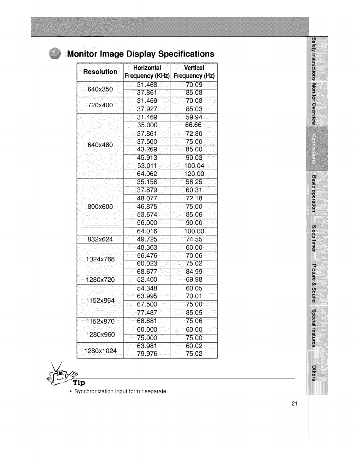
Monitor Image Display Specifications
Vertical
Frequency (Hz)
A 56.000 _ 90.00
" 64.016 _ 100.00
48,363
68.677 84.99
54.348 60.05
63.995 I 70.01
67.500 _ 75,00
1152X870 68.681 _ 75,06
iiiiiiii_:_!_!ii!ii!ii!ii!ii!ii!ii!ii!ii!ii!ii!ii!ii!ii!ii!ii!ii!_i!_i!_!ii_i_iiii
. Synchronization inputform ' separate
21
PC
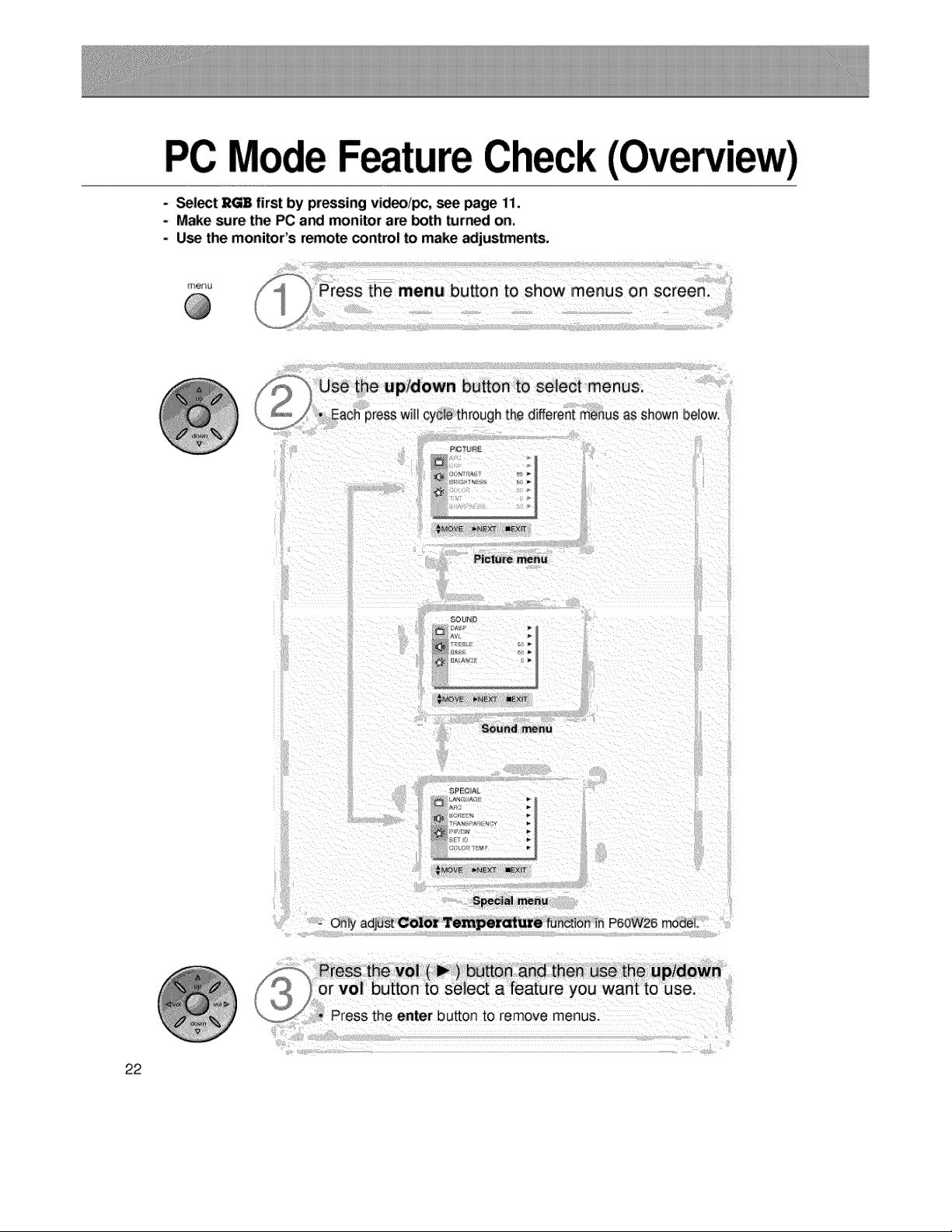
- Select RGB first by pressing video/pc, see page 11.
- Make sure the PC and monitor are both turned on.
- Use the monitor's remote control to make adjustment.
Use the up/down button to select menus,
* Each press wil_ cycle through the different menus as ShOwnbelow.
S_cla! menu
- only adjust Color Temper_ure run.ton in P6ow26 model
Press the vol ( _ ) bu_n and _hen use the up/down
_/_ orvo_buttontoselectafeatureyouwan_touse.
_ _ Press the enter button to remove menus.
22
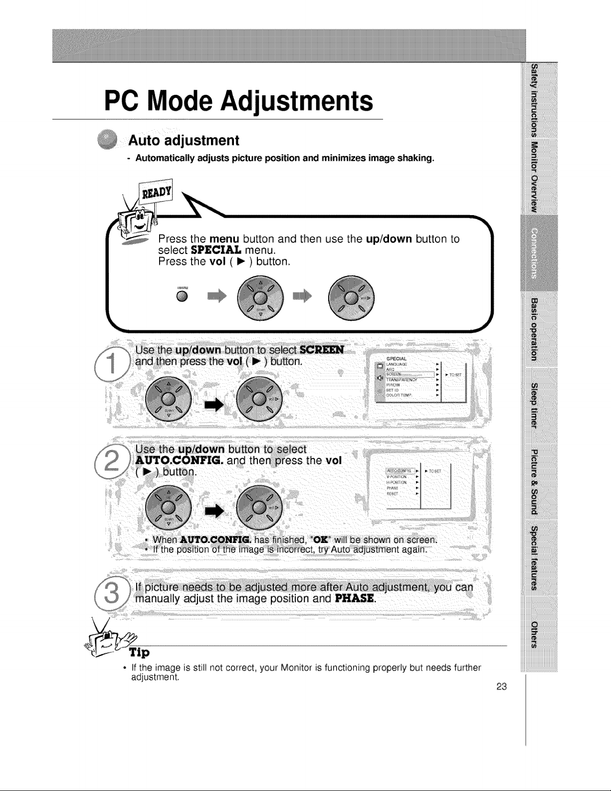
- Automaticaily adjusts p_ture position a_ minimizes image s_king.
Press the menu button and then use the up/down button to
select SPECI_ menu.
Press the vol ( I_ ) button.
@
tton to select
1press the vol
OK will be Shown on sc[een.
If picture ne_s to be adjusted more _er Auto adjustment, you can
m&nualiy adjust the ima_le position and PHASE.
• If the image is stilt not correct, your Monitor is functioning properly but needs further
adjustment.
23
Adj
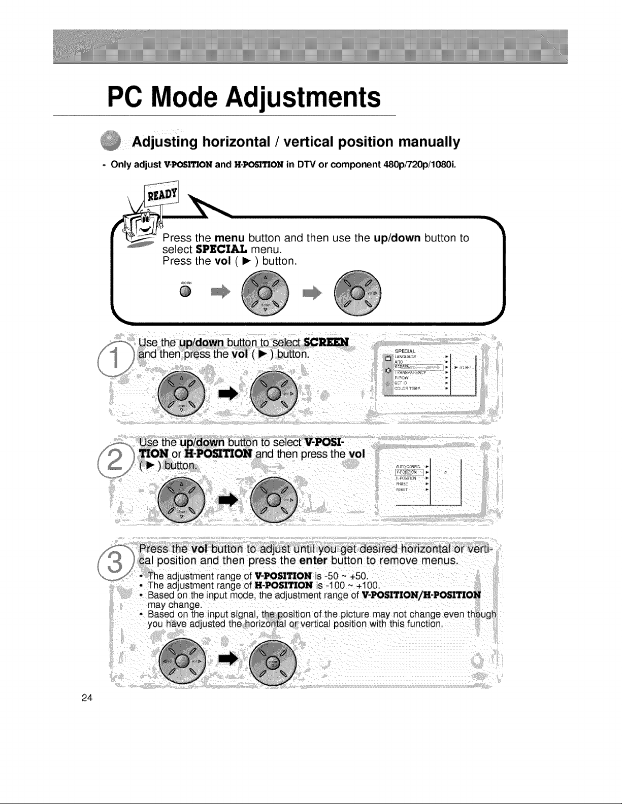
i Adjusting horizontal /vertical position manually
- Only adjust V*_q1ON and HoP_ON in DTV or compo_nt 480p/720pi10_i.
\
Press the menu button and then use the up/down button to
select $PI_CZ&L menu.
_PECIAI
__'_ Press the vol button to adjust until you get desired hodzonta} or verti-
cal position and then press the enter button to remove menus.
_j_ * The adjustment range of WPOSI_ON is -50 ~ +50
may change.
• Based on the input signal, the position of the picture may not change even though
yO usted the horizontal or vertical position with this function_
24
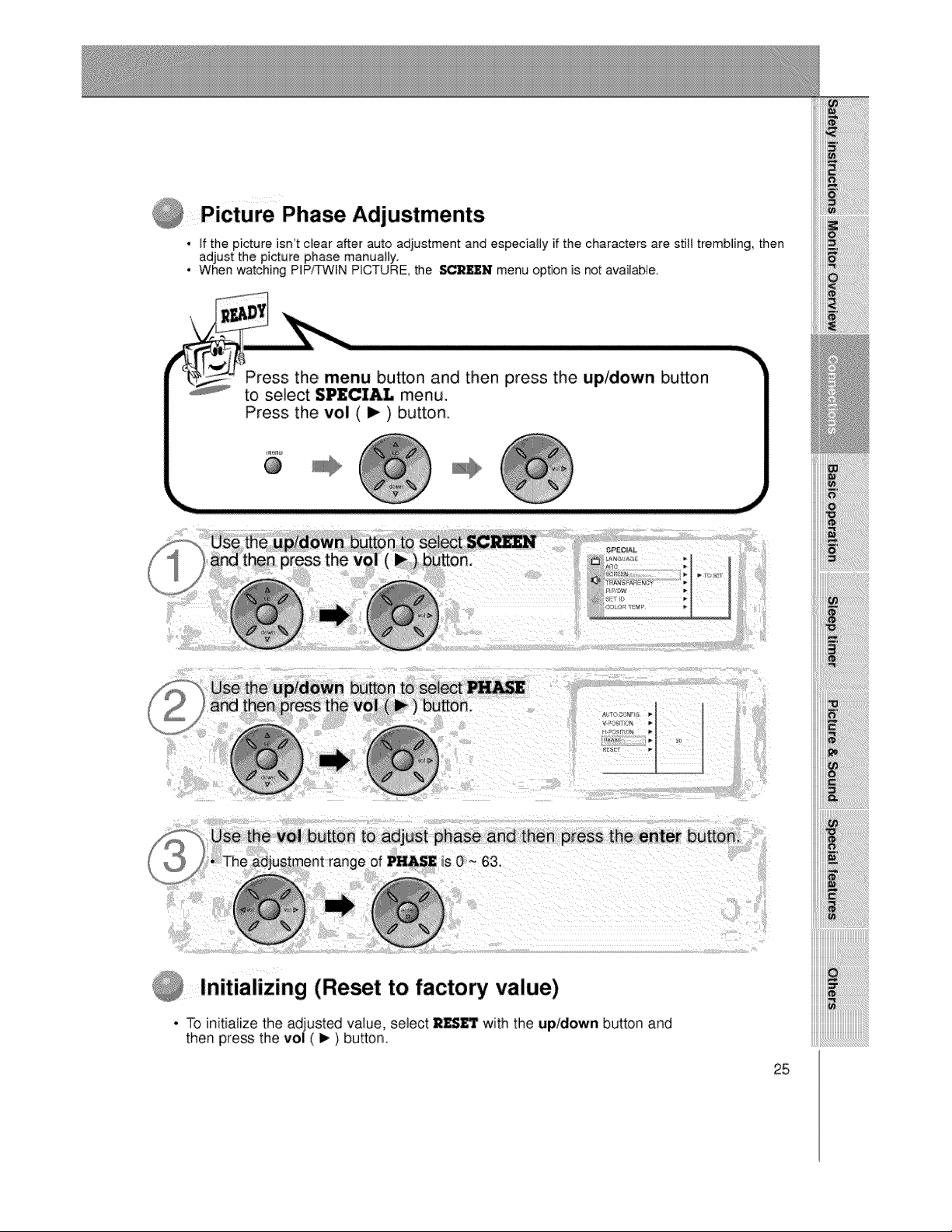
Picture Phase Adjustments
• If the picture isn't clear after auto adjustment and especially if the characters are still trembling, then
adjust the picture phase manually.
• When watching PIP/TWIN PICTURE, the SCREEN menu option is not available.
Press the menu button and then press the up/down button
to select SPECIAL menu,
Press the vol ( i_ ) button.
_n_
@
to adjust phase and then press the enter button.
is 0 ~ 63.
Initializing (Reset to factory value)
• To initializethe adjusted value, select RESET with the up/down button and
then press the vol ( I_ ) button.
25
In
PIP lets you view 2 different inputs (sources) on your monitor _reen at the same time. One source will
be large, and the other source will show a smaller inset im_age.
Select ]R_ input source before pressing PiP.
This function works only in the following resolutions;
640x480, 800x600, i024x768 (only in Vertical frequency 60 Hz)
When you select RGB or DTV for main picture in PIP/Twin picture, you can watch video, cable TV or
DVD for sub picture.
Color of main picture may be different from PIP's in PIP/Twin picture mode.
If input source for main picture is changed while in PIP/Twin picture mode, sub picture wig disappear.
When watching PIP/Twin picture, SC_ option is not available in Special menu.
With PIP active, not all picture formats can be used for the main/sub picture.
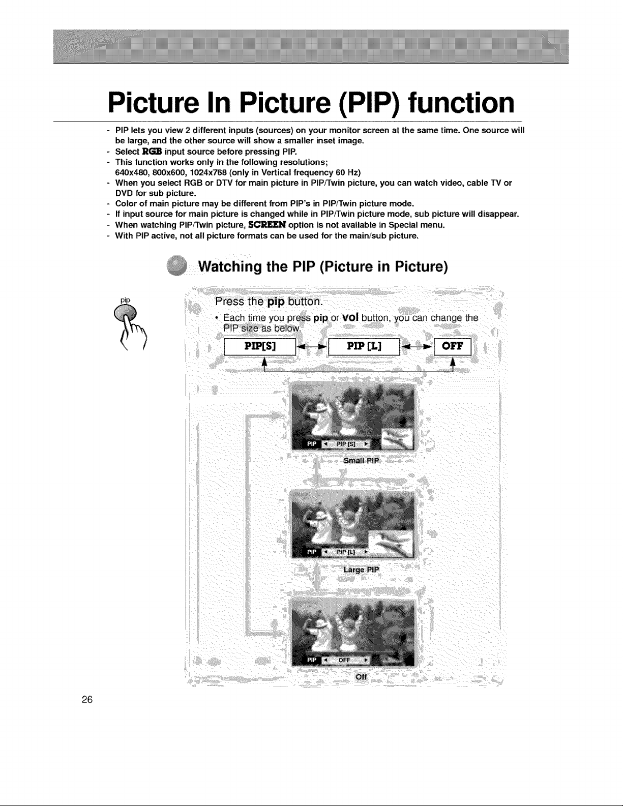
"Watching the PIP (Picture in Picture)
pip
Press the pip button.
the
Small PiP
Large PiP
26
off
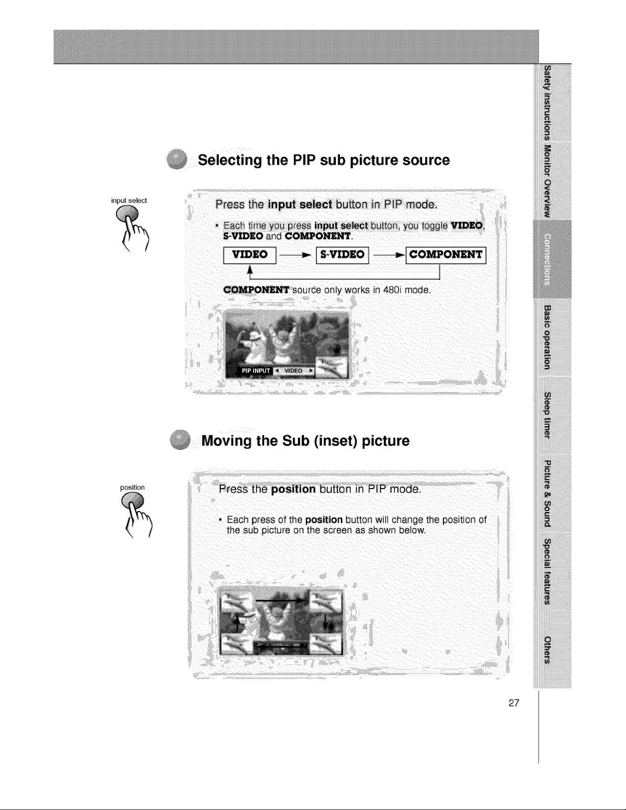
Selecting the PIP sub picture source
inp_ select
i
Moving the Sub (inset) picture
27
In
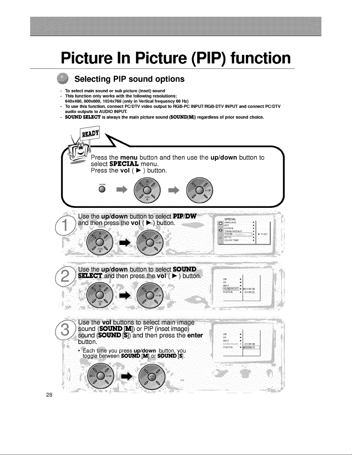
;lecting PIP sound options
- To select main sound or sub picture (inset) sound
- This funct_n only works w_th the follow_ng resolutions;
640x480, 800x600, 1024x768 (only in Vertical frequency 60 _)
- To use this function, connect PC/DTV v_ output to RGB-PC INPUTiRGB-DTV INPUT and connect _1_
audio outputs to AUDIO INPUT.
SO_ _IJE_ is always the main picture sound (SO1LfNI_) regardless of prior sound choice.
Press the menu button and then use the up/down button to
select $P£CI&I. menu.
Use the vol buttons to select main image
sound (80_ ['_) or P_P (inset image)
_und (SO_ [S]) and then press the enter
button.
press up/down button, you
[S].
28
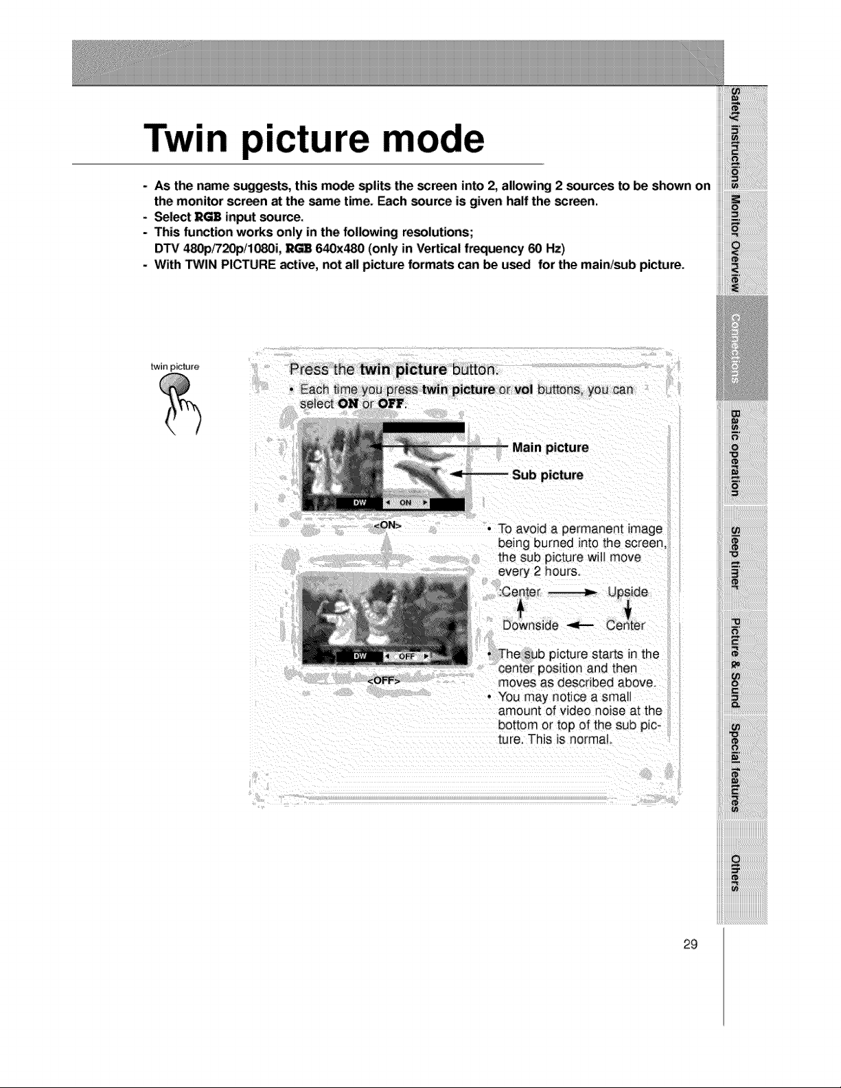
Twin picture mode
- AS the name suggests, this m_ spli_ the screen into 2, aUowing 2 _urces to _ shown on
the monitor screen at the same time. _ch _urce is given half the scan.
- Select RG8 input source.
- This _r_tion works only in the following re_lutions;
DTV 4_/720p/10_3i, _ 640x480 (only in Vertical frequency 60 Hz)
- With _IN PICTURE active, not all picture forma_ can _ used for the main/sub picture.
twin picture
Press the twin picture huron.
Each ttme
sele_ ON
<ON>
• To avoid a permanent image
being burned into the screen,
the sub picture will move
amount of video noise at the
bottom or top of the sub pic-
ture. This is norma_
29
Twin picture
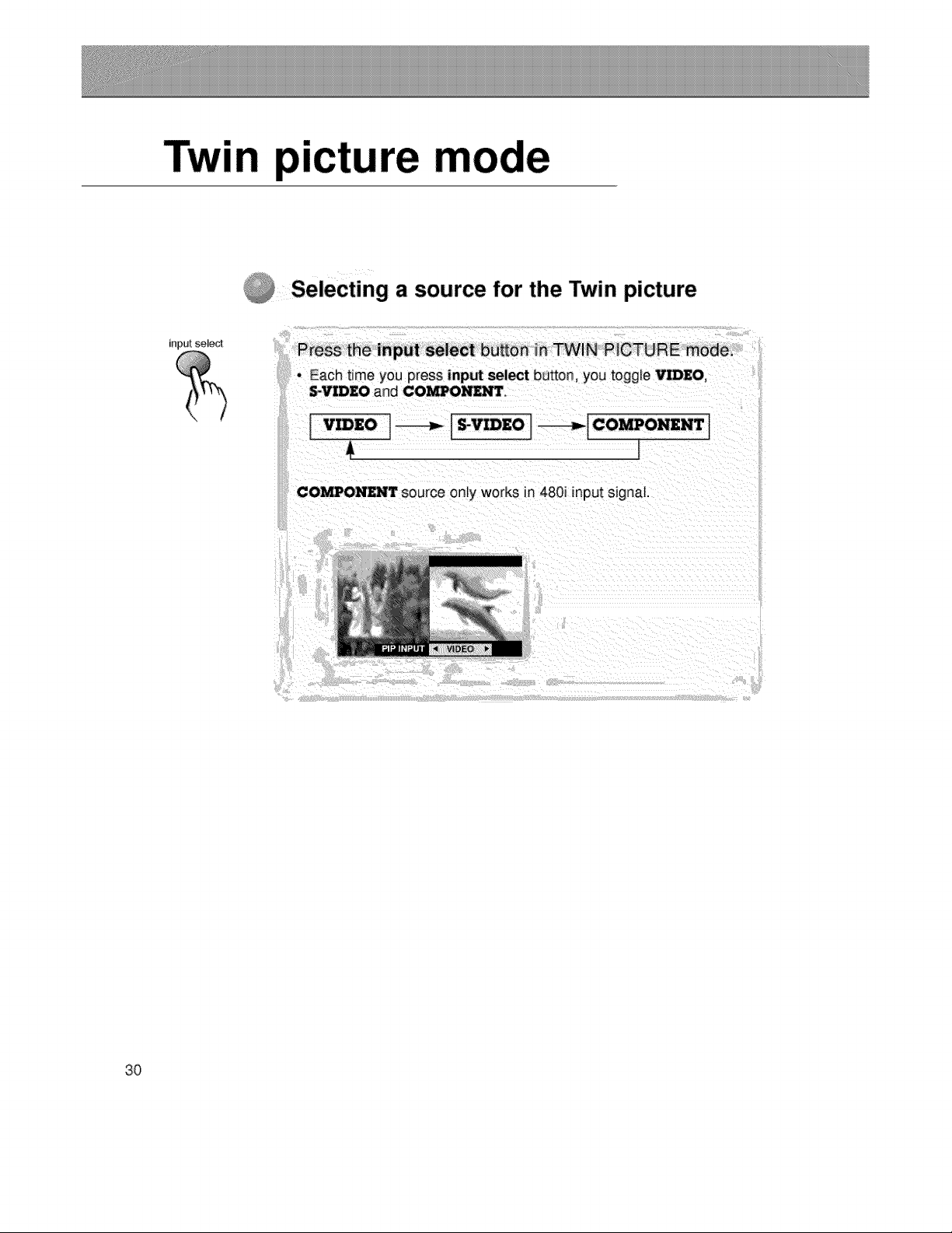
Selecting a source for the Twin picture
input select
Press the input sele_ button in TWIN PICTURE mode,
• Each tree you press input select button, you toggle V_EO,
S+VIDZO and COMPOND_rr+
I Eo I_ I_z° i---_Ic°mP°"_" t
COMPONENT source only works in 4801 input signal.
3O
Using the
control
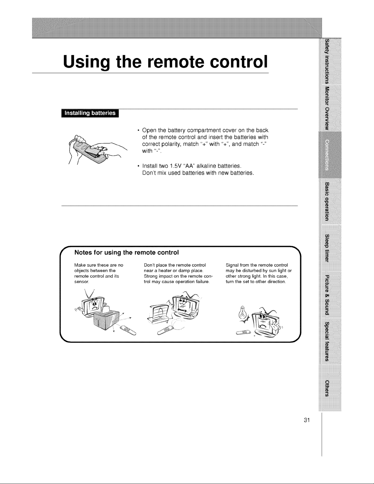
• Open the battery compartment cover on the back
of the remote control and insert the batteries with
correct polarity, match "+" with "+', and match "-"
with ":'
• Install two 1.5V "AA" alkaline batteries.
Don't mix used batteries with new batteries.
Notes for using the remote control
Make sure these are no
obits between the
remote control and its
sensor,
Don't place the remote c_ntroU
near a heater or damp place,
Strong impact on the remote con-
trol may cause operation failure
Signal from the remote control
may be disturbed by sun ligN or
other strong _ight. In this case,
turn the set to other direction.
31
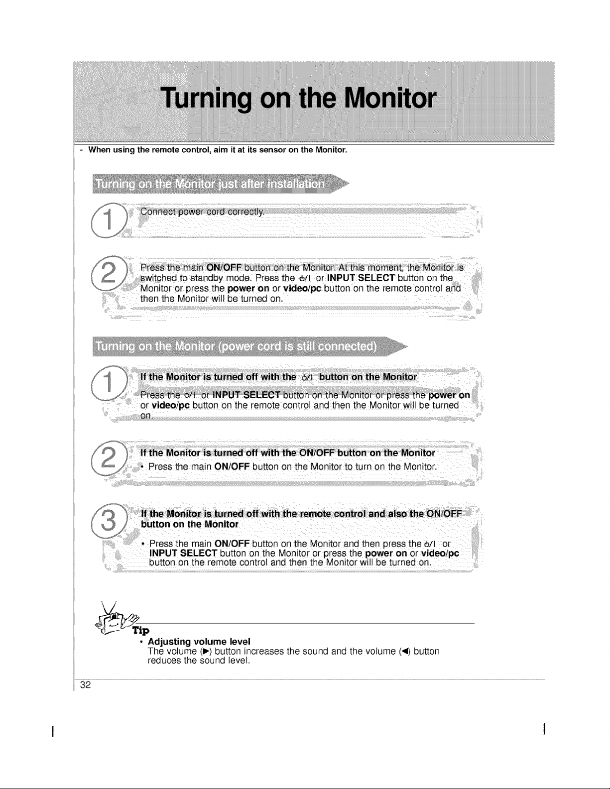
When using the remote control, aim it at its sensor on the Monitor.
,!!_!i_!'i'ii!
- Adjusting volume level
The volume (I_) button increases the sound and the votume (_1)button
reduces the sound level
32
I I
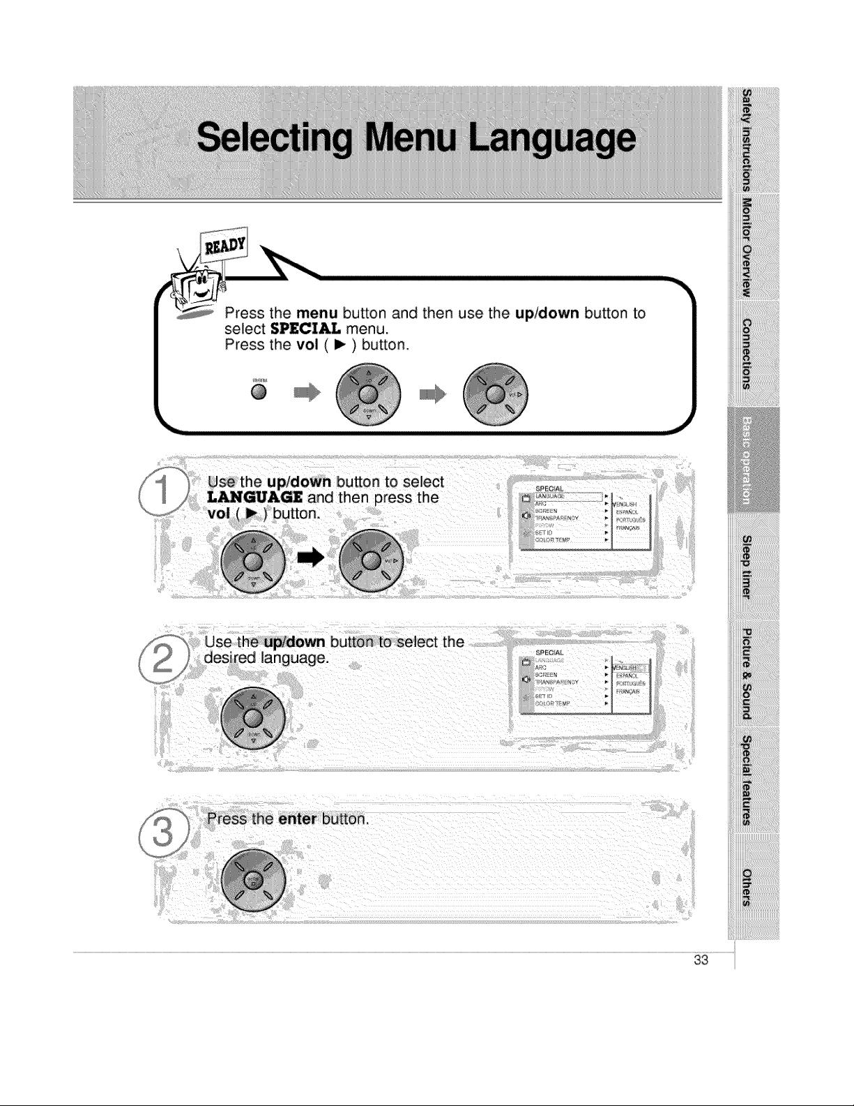
Press the menu button and then use the up/down button to
select SPECIAL menu.
Press the vol (1_) button,
@
ii_i!_!_iii_i(i_ii___ii_i_iilill_iliiii_=iii_i_ii iii_i i !_i_i _ !
Press the enter button.
33
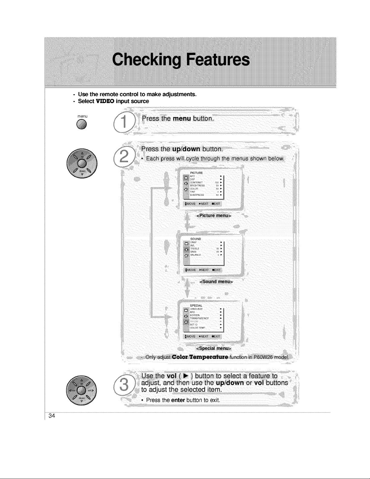
- Use the remote control to make adjustments.
- Select Vm£O input source
menu
@
J
Press the menu button.
Press the up/down button_
Each press will cycle through _he menus shown below.
PIGT_,JBE
_VB _4_l_g allENr_
<Picture menu>
<Sound menu>
<Special menu>
- Only adjus_ Color Temper_ure _nctbn in P60W26 mOdeL
Use the vol ( _ ) button to select a featu re to
_ ] adjust, and then use the up/down or vol buttons
to adjust the selected item.
. Press the enter button to exit,
34
iiiiii!i
_i Diiiiiiiiiiiiiiiiiiiiiiiiiiiiiiiiiiiiii[iii_i_i_i_i_i_i_i_iiiiiiiiiiii
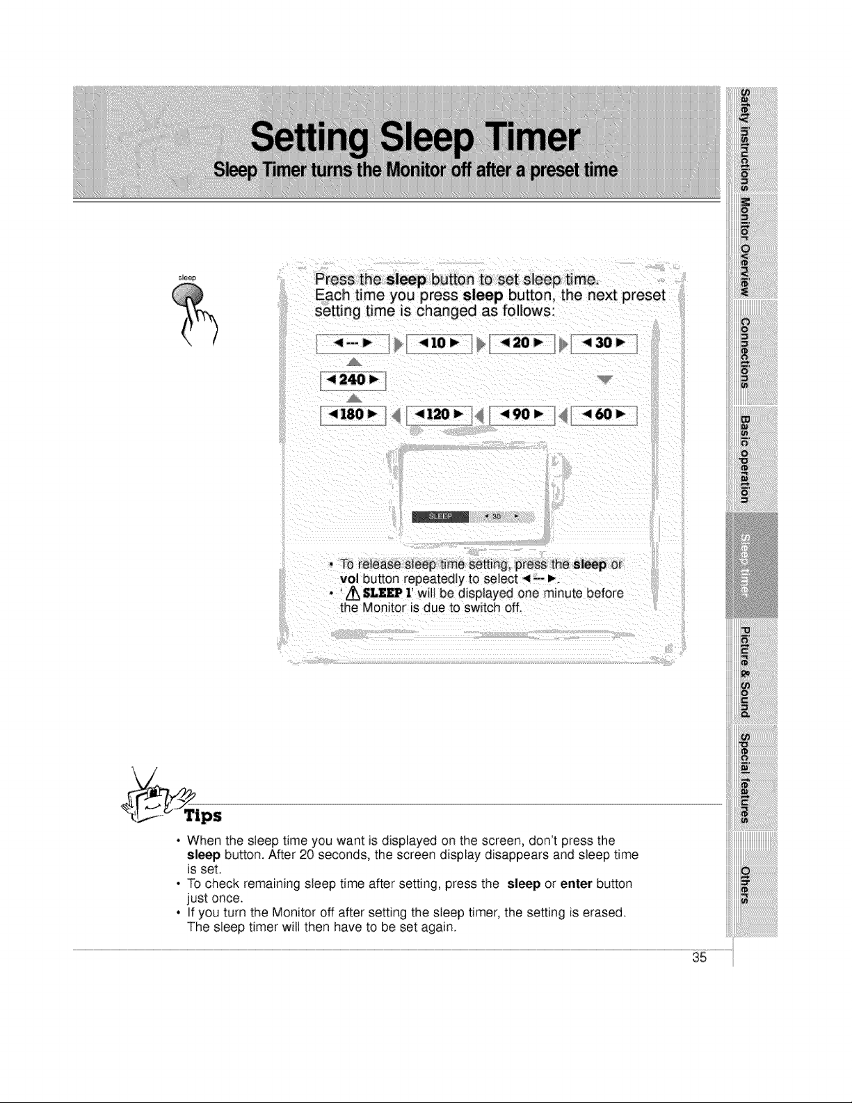
Press the Sl_p button tO set sleep time,
Each time you press sleep button, the next preset
setting time is changed as follows:
4--_ _ <I0 I" <20_ <,30_
< 240 )"
< 180 I__/ _ _-4 i_ _I j _< 90 I_
• To release steep time setting, press the sl_ or
vol button repeatedJy to select ,4-- _,.
• ' Z_ SLZ£P 1' wNIbe displayed one minute before
the Monitor is due to switch off.
• When the sleep time you want is displayed on the screen, don't press the
sleep button. After 20 seconds, the screen display disappears and sleep time
is set.
• To check remaining sleep time after setting, press the sleep or enter button
just once.
• If you turn the Monitor off after setting the sleep timer, the setting is erased.
The sleep timer will then have to be set again.
35
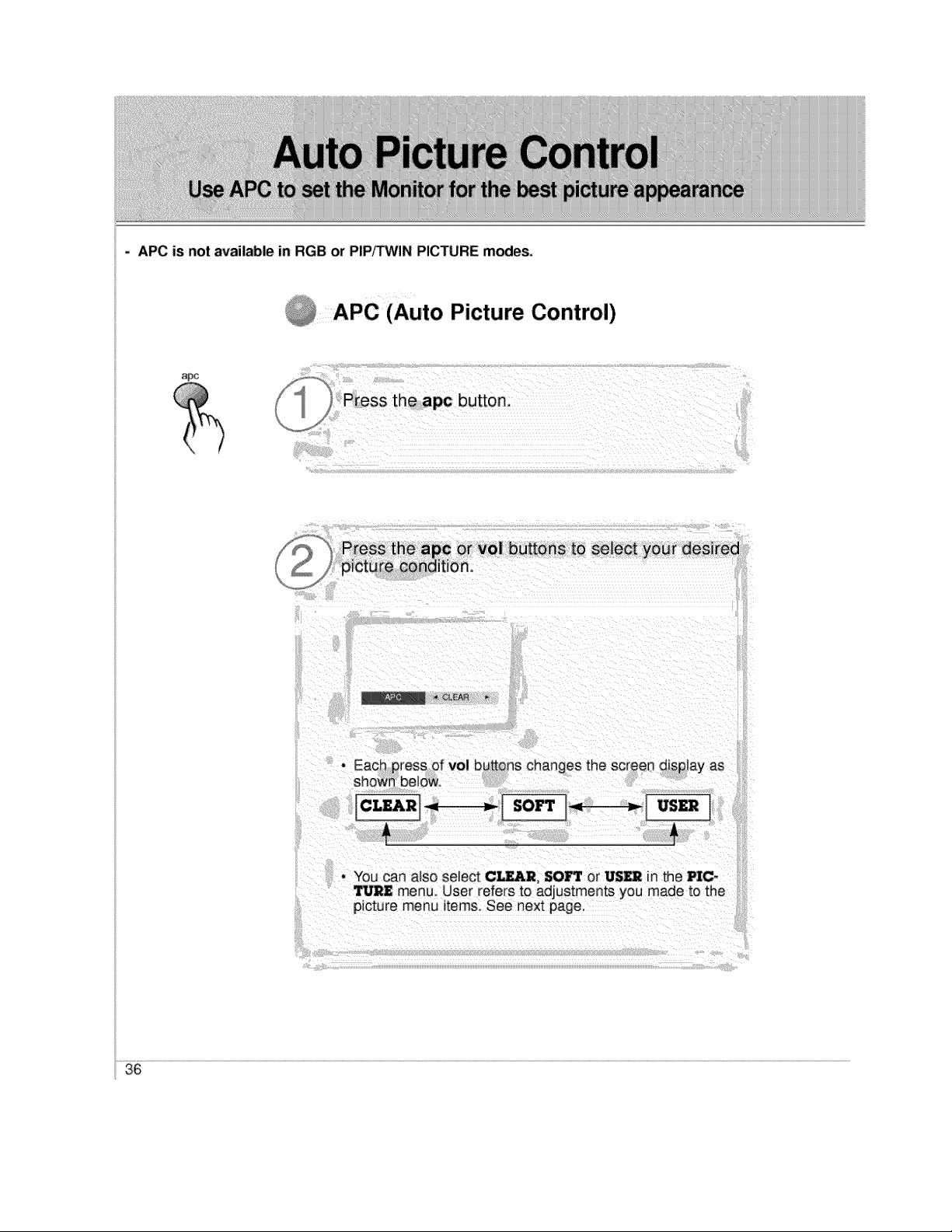
- APC is not available in RGB or PIP,q'WIN PICTURE modes.
APC (Auto Picture Control)
Press the apc or vol buttons tO select your desired
picture condition,
_ iCLEAR _,
. EaCh press of vol butt_ns changes the screen disp ay as
shown belew_
CLEARI_t-------_ SOFT : -_I USER I
- You can also select CLEAR, SO_ or US_ n the P]C-
",J_II menu. User refers to adjustments you made to the
icture menu items. See next page.
36
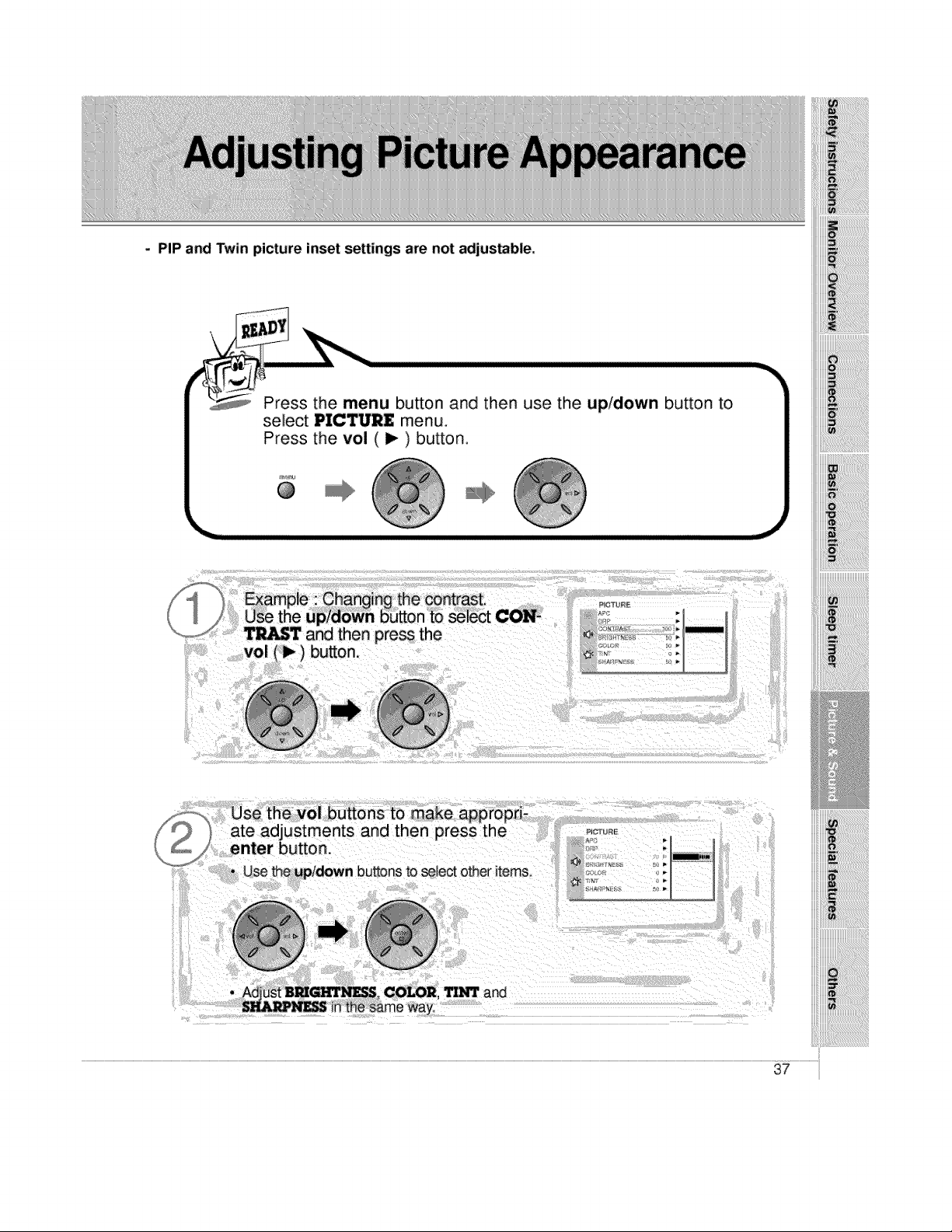
- PIP and Twin picture inset se_ings are not adjustable.
i Press the menu button and then use the up/down button to
select PICTURE menu. |
Pr_s the vol ( I_ ) button I
enter button.
, Use the upldown buttons to seJect other items,
PIC,_ L_RE
P
COLOR, _ and
37
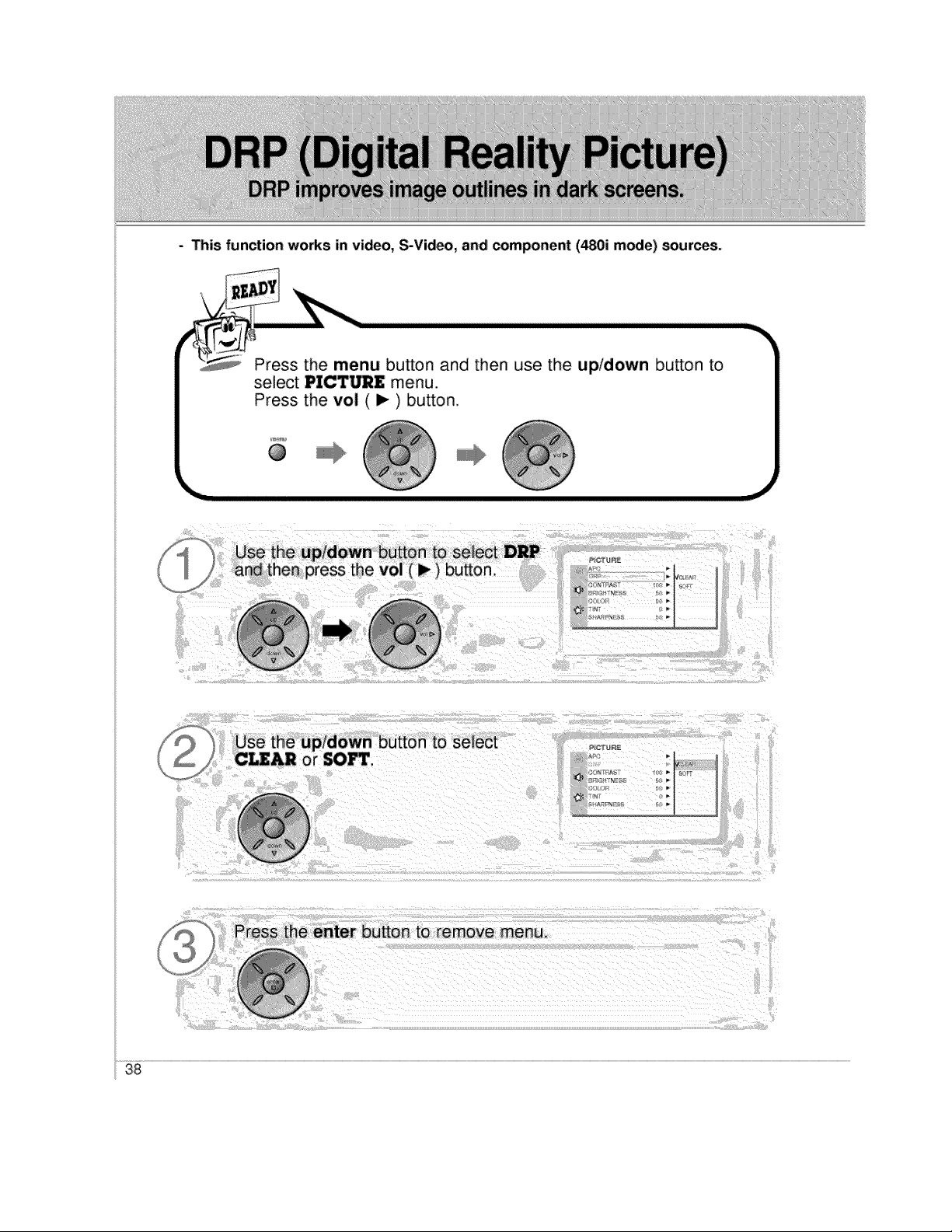
- This function works in video, S-Video, and component (480i mode) sources.
\
Press the menu button and then use the up/down bu_on to
select PICTURE menu.
Press the vol ( ) ) button.
@
38
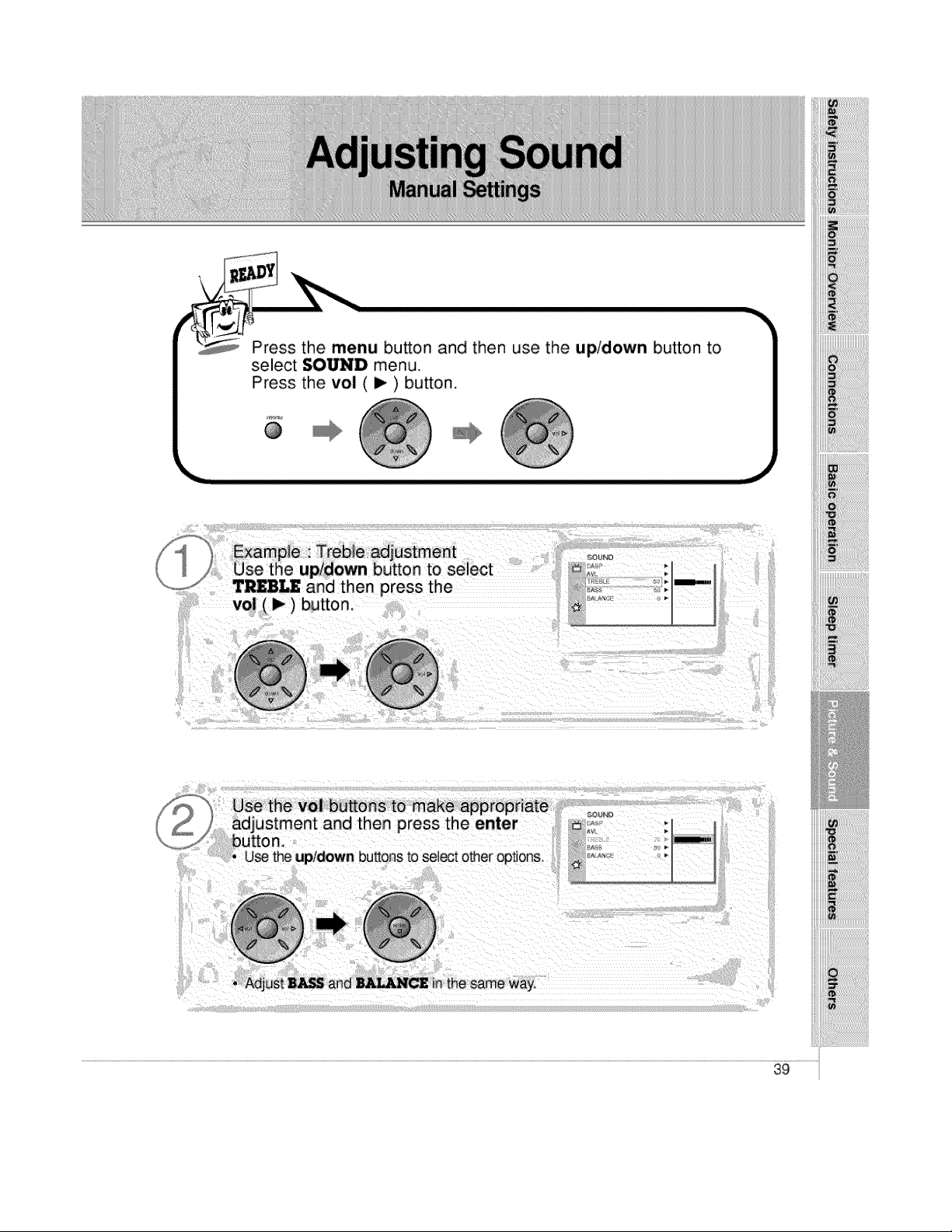
Press the menu button and then use the up!down button to
select SOUND menu.
Press the vol (i_) button.
@
i!!i!!i!!i!!i!!i!!i!!iiii!iiiii
iiii!_iiiiiiiiiiiiiiiiiiiiiiiiiiiiiiiiiiiiiiiiiiiiiiiiii!_i
iiii_i_!iliiiiiii!i!!iiiiiiiiiiiiiiiiiiiiiiiiiiii_ii_i_i_i_i_i_i_i
i!i_ii_i_iiiii!!iiiiiiililililililililili_ii_ii_iiiiiiiiiiiii_!i!!!!!
!i!_i_i_i!_i!_i!_i!_i!_i!_i!_i!_i!_i!_i!_i!_i!i_!ii_i!_!i!i!!!_ii!ii!ii!_i__
'i'i'i
Use the vol buttons to make appropriate
adjustment and then Dress the enter
button.
• use the upldown buttons to select other options,,
39
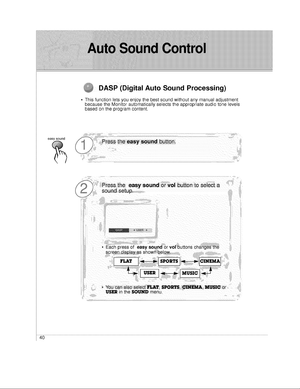
_DASP (Digital Auto Sound Processing)
• This function lets you enjoy the best sound without any manual adjustment
because the Monitor automatically selects the appropriate audio tone levels
based on the program content
easy sound
Press the easy sound or vo] button to select a
sound setup.
J
• You can also select MAT, S_R_. CIN_, _IC Or
US£2 in the SO/_ menu.
40
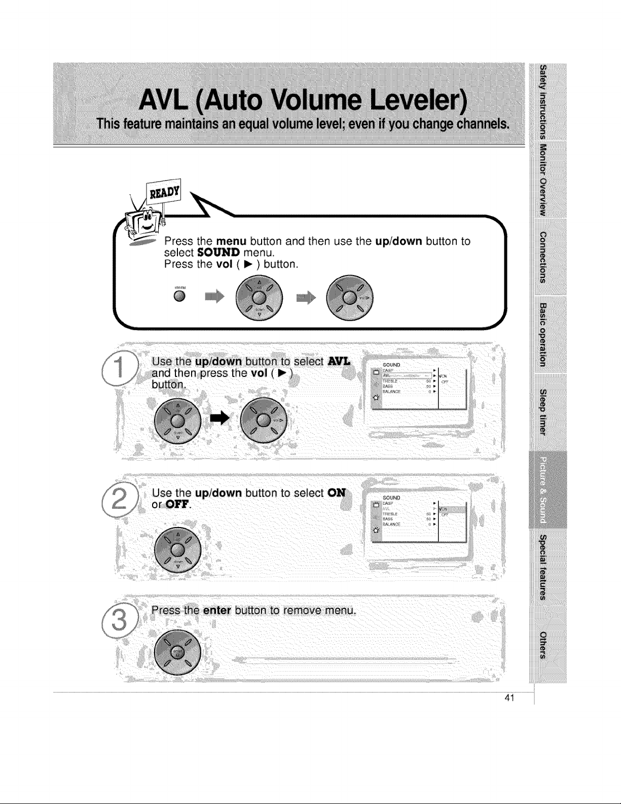
Press the menu button and then use the up/down bu_on to
select SOUND menu.
Press the vol ( I_ ) button,
@
Jse the up/down button to select AVL
S _nd then press the vol (I_)
,,,t button
Use the up/down button to select ON
or OFF.
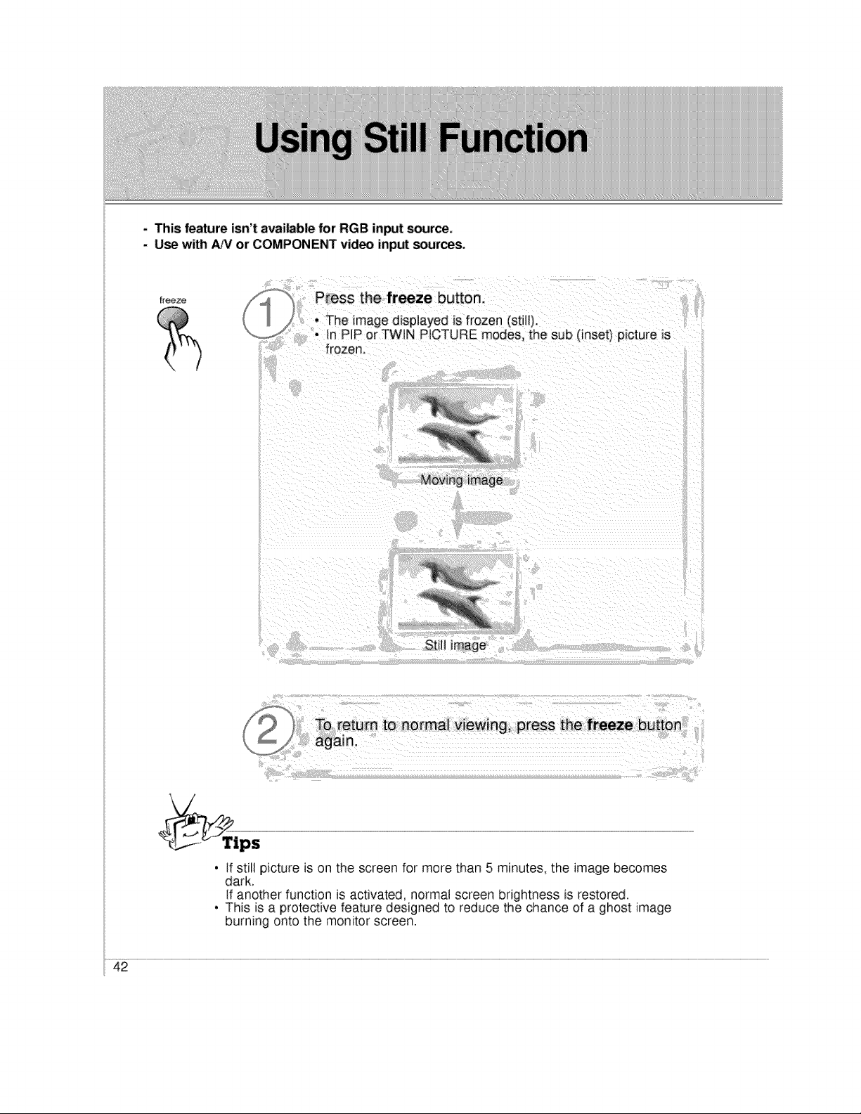
- This feature isn't available for RGB input source,
. Use with ,&JVor COMPONENT video inp_ sources_
freeze
Press the freeze button,
• The image displayed is frozen (stW).
• In P P or TWIN PICTURE modes, the sub (inset) picture Js
frozen,
Still image
4
• if still picture is on the screen for more than 5 minutes, the image becomes
dark.
if another function is activated, normal screen brightness is restored.
• This is a protective feature designed to reduce the chance of a ghost image
burning onto the monitor screen.
42
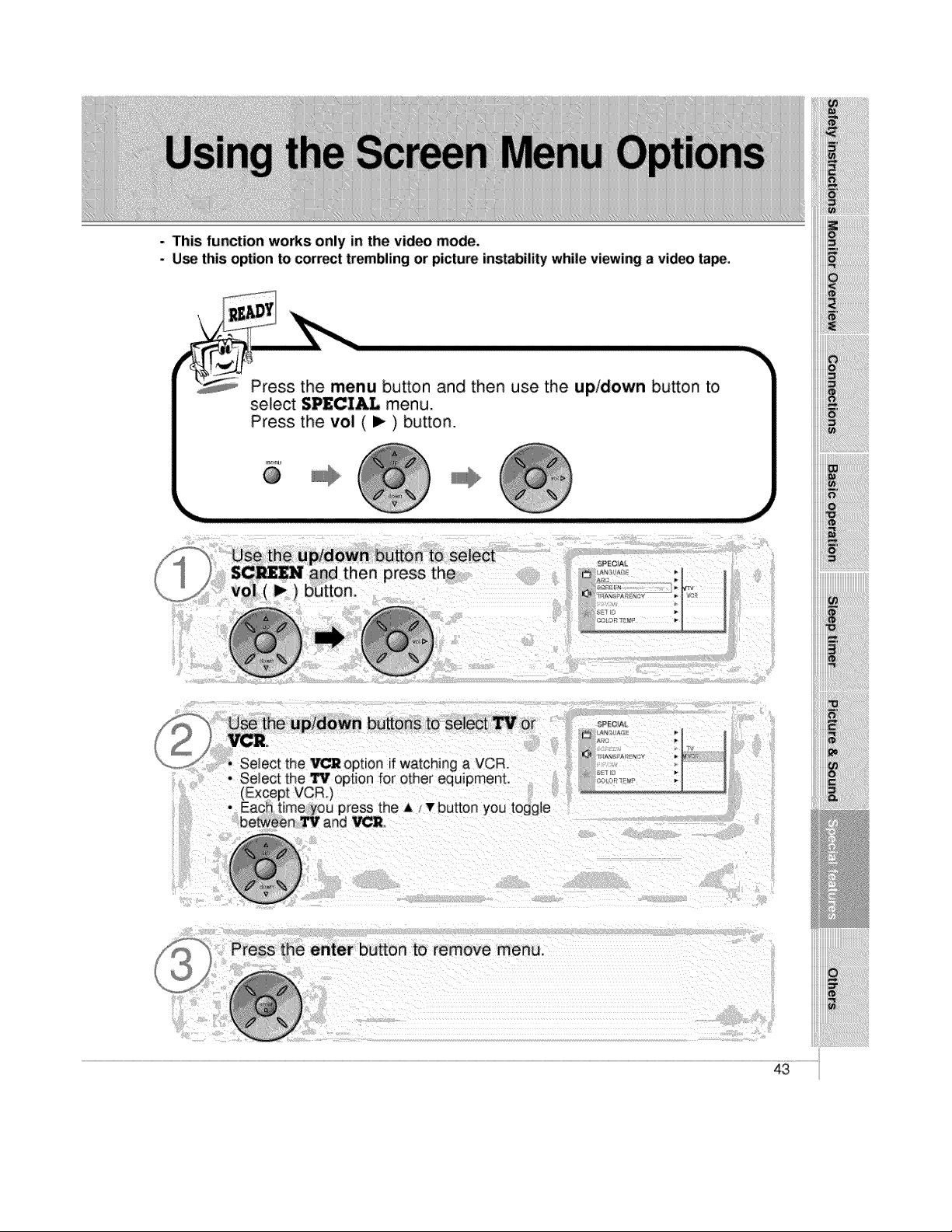
- This function works only in the video mode.
- Use this option to correct trembling or picture instability while viewing a video ta_,
Press the menu button and then use the up/down button to
select SPECIAL menu.
Press the vol ( I_ ) button.
_'nu
@
_.J
to select
)tess the
• Select the VCR option if watching a VCR
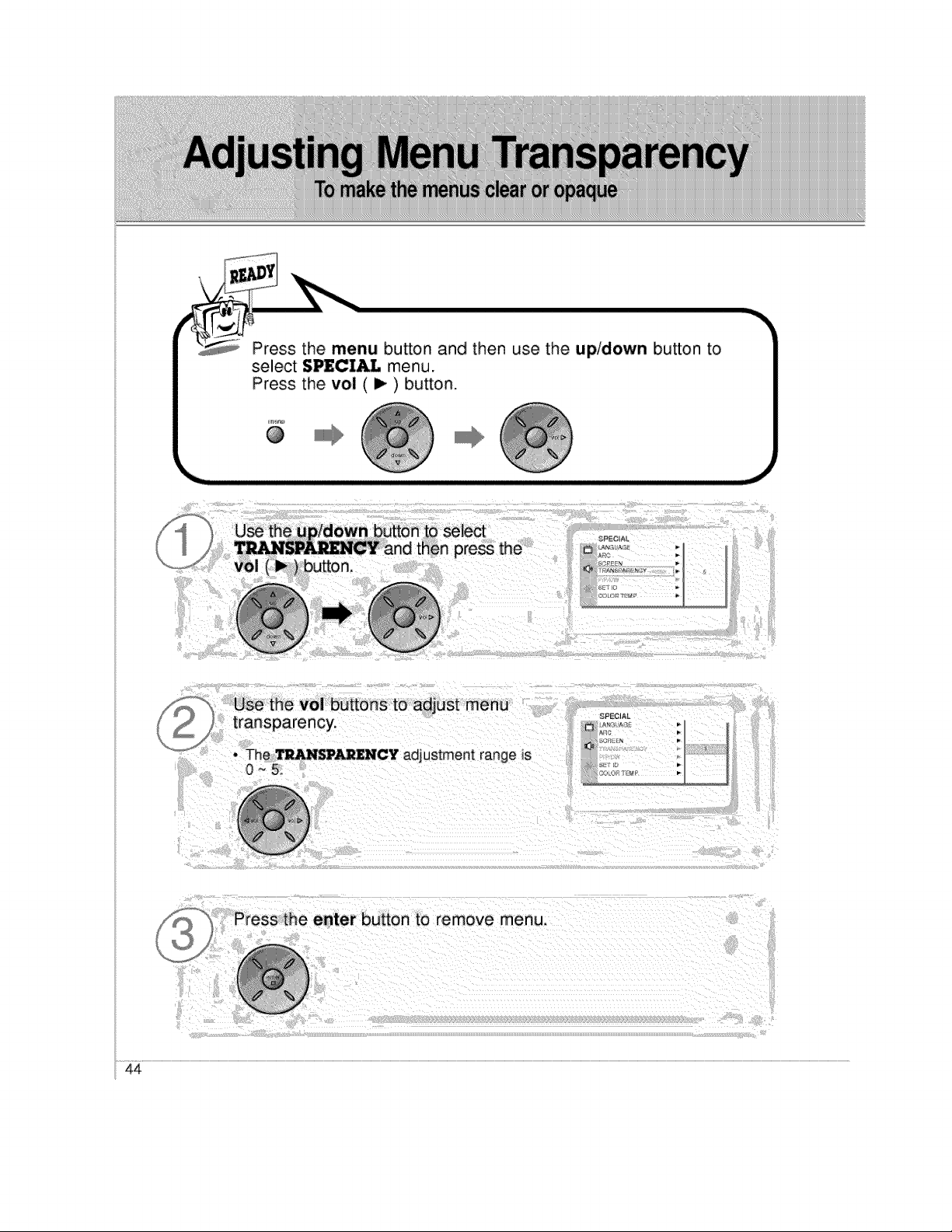
Press the menu button and then use the up/down button to
select SPECIAL menu.
Press the vol ( i_ ) button.
@
III1_
_, Press the enter button to remove menu.
44
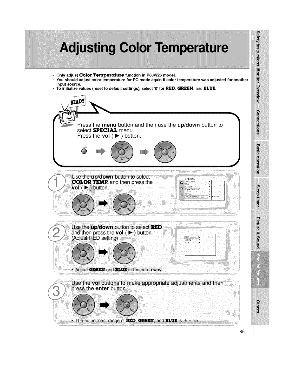
Only adjust Color Temperature function in P60W26 model
- You should adjust color temperature for PC mode again ff color temperature was adjust_ for another
input source.
- To initialize values (reset to default settings), select '0' for R_, _UN, and BL_.
Press the menu button and then use the up/down button to
select SPECIAL menu.
Press the vol ( I_ ) button.
menu @
@
F -_, Use the up/down button to seiect
] COLOR T_, and then press the
/ vol (_) button.
_iiiiiiiiiiiiii!!!!i_
_!_!_i_i!i_ii_ii_i!ii!_i!_!!i_!_i_!i_!i_!ii!ii!ii!ii!ii!ii!ii!ii!i_!i_i!!i_i_!i_J_!_
'i'i'i
the same way,
then
adjustment range of
45
`[_!_!_!i_!i_!i_!i_!i_!i_!i_!i_!i_!i_!i_!i_!i_!i_!i_!i_!i_!i_!_!_i_i_!_
!iii!i!iii!!!ii_!_!!_!!_!!_!!_!!_!!_!!_!!_!!_!!_!!_!!_!!_!!_!!_!!_!!_!!_!!_!!_!!_!!_!!_!!_!i_!!!!!i_i!i
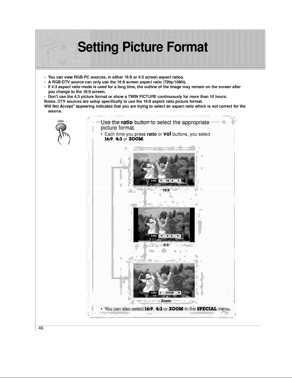
You can view RGB_PC sources, in either 16:9 or 4:3 screen aspect ratios.
- A RGB-DTV source can only u_ the 16:9 _reen asset ratio (720p/1080i).
- If 4:3 aspect ratio mode is used for a long time, the outline of the image may remain on the screen after
you change to the 16:9 screen.
° _n't use the 4:3 picture format or show a TWIN PICTURE continuously for more than 10 hours.
Notes: DTV _urces are setup specifically to use the 16:9 aspect ratio picture format.
Will Not Accept" appearing indicates that you are trying to select an aspect ratio which is not correct for the
source.
ratio
Use the ratio button to select the appropriate
picture format.
• EaCh time you press ratio or vol buttons,you select
16,,9, 4:3 or ZOOM_
16:9
4:3
Zoom
• You can a_sose_eot16.,9, _3 or ZOOM in the SPECIAL menu.
46
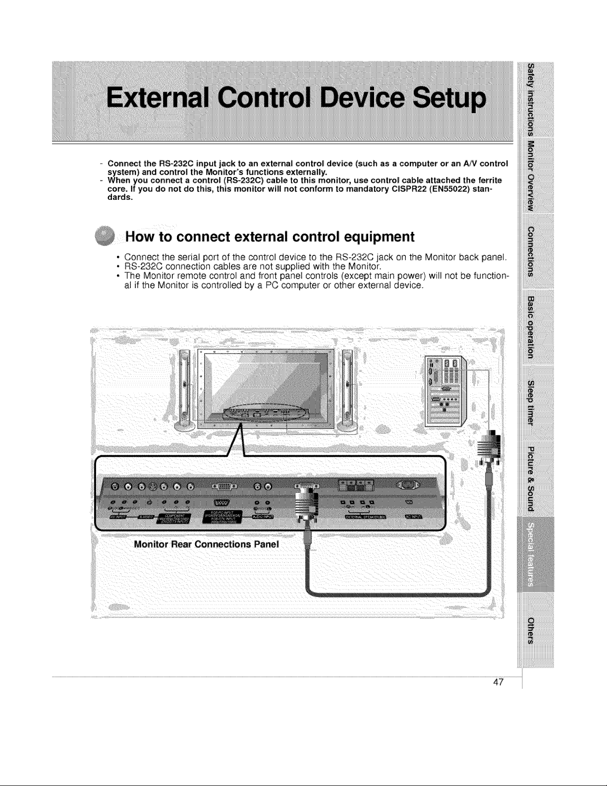
= Connect the RS-232C input jack to an external control device (such as a computer or an _V control
system) and control the Monitor's functions externally.
When you connect a control (RS-232C) cable to this monitor, use control cable attached the ferrite
core. If you do not do this, this monitor will not conform to mandatory CISPR22 (EN55022) stan-
dards.
How to connect external control equipment
• Connect the serial port of the control device to the RS-232C jack on the Monitor back panel
. RS-232C connection cables are not supplied with the Monitor.
• The Monitor remote control and front panel controls (except main power} wilJ not be function*
al if the Monitor is controlled by a PC computer or other external device.
iiii!i!i!i!i!i!i!i!i!i!i!i!i!i!i!i!i!!iiiiiiiiiiiiiiii!ii!iiiiiill
!_!_!_!_}ii_!_i_i!_!!_!!_!!_!!_!!_!!_!!_!_!!_!_!_!_!i_!_i!i_!_!_!!_!i!i!_!i!i_i!i
iii_i;,!_ii_!i'i;!;!;!;!;!;!;!;!;!;!;!_ii_ii_iiii_ii_ii_ii!!ii_i!il
iiii!ii,_;i_;j;;i_!ili!ii!ii!ii!ii!ii!ii!ii!ii!ii!ii!i_i_i_iiiiiiii
ii_i_iiii_iiiiiiiiiiiiiiiiiiiiiiiiii_i_i_i_ililililili_!;i:_;_
Monito r Rear Connections Panel
47
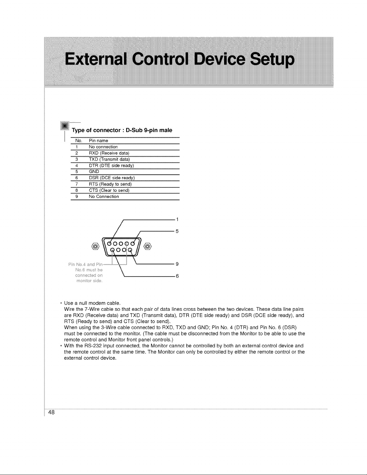
@°°_e of connector : D-Sub _pin male
Pinname
1
2
3
4
5
6
7
8
9
No conned:ion
RXD (Receive data)
TXD (Transmit da_3)
DTR (DTE side ready)
GND
DSR (DCE side ready)
RTS (Ready to send)
CTS (Clear to send)
No Connection
1
5
@ 000 ' @
6
* Use a null modem cable
Wire the 7-Wire cable so that each pair of data lines cross between the bt¢o devices. These data line pairs
are RXD (Receive data) and TXD (Transmit data), DTR (DTE side ready) and DSR (DCE side ready), and
RTS (Ready to send) and CTS (Clear to send).
When using the 3oWire cable conn_t_ to RXD, TXD and GND; Pin No. 4 (DTR) and Pin No 6 (DSR)
must be connected to the monitor. (The cable must be disconnected from the Monitor to be able to use the
remote controt and Monitor front panel controls.)
, With the RS-232 input connected, the Monitor cannot be controtl_ by both an external control device and
the remote control at the same time. The Monitor can only be controlled by either the remote control or the
external control device.
48
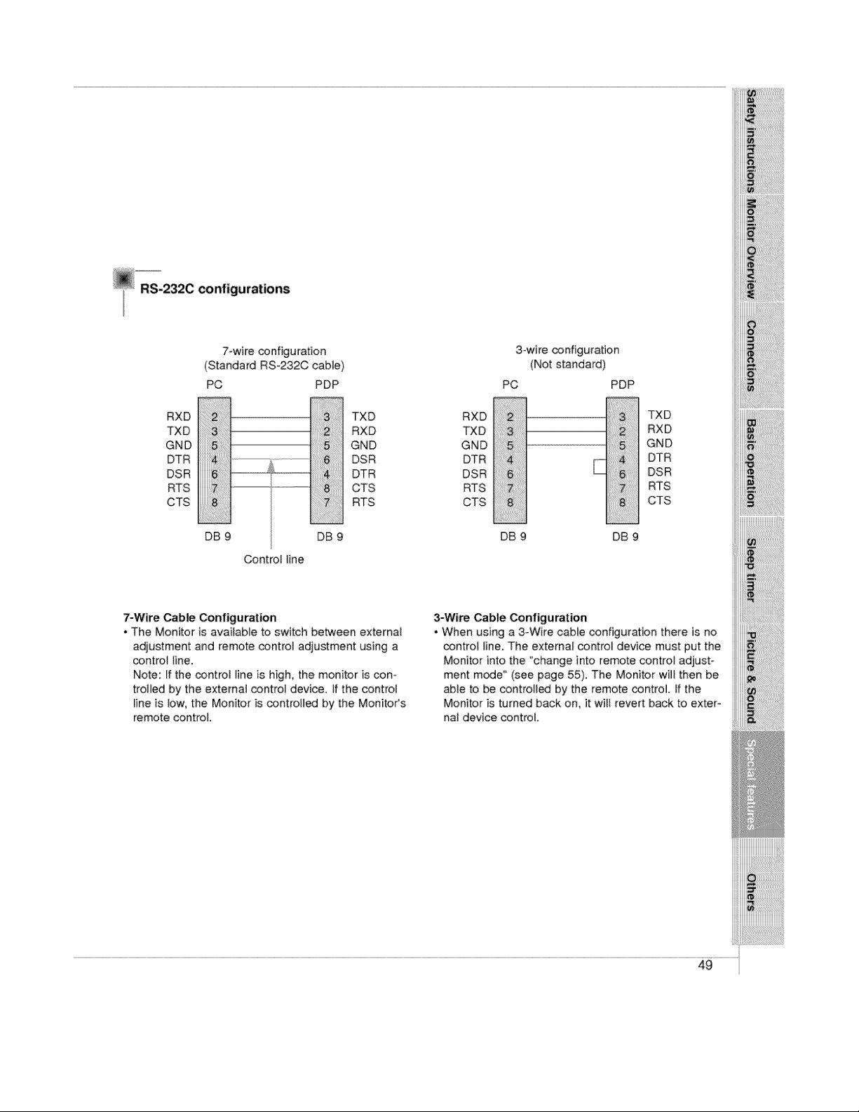
RS-2320 configurations
7-wire configuration
(Standard RS-232C cabte)
PC PDP
RXD 3:;;;;;: TXD
TXD RXD
GND GND
DTR DSR
DSR L .............. DTR
RTS ............. CTS
CTS RTS
DB 9 DB 9
Control line
RXD
TXD
GND
DTR
DSR
RTS
CTS
3owire configuration
(Not standard)
PC PDP
!iiiliii;:i;iii;13i;ii%! ii!!i!!!!!!!!!!jili_i:!i!iiiiiiiiiljiSi;;i
iiii!i!i!i!iiiiiii!iiiiiiS!i_ii_ii_iiiiiii_!;!;!;!ii:il..........................................
:ii!i!i!i;iii!ii!i!!ii!iii6;il;il;il;il;i;i;i:i:iiiii
DB 9 DB 9
TXD
RXD
GND
DTR
DSR
RTS
CTS
iiiiiii!_;i%;_i;_i;i_!iiiii!!i!ii!ii!ii!i;i!;!ii!ili_ii_ii_iiiiill
7-Wire Cable Configuration
• The Monitor is available to switch between external
adjustment and remote control adjustment using a
control line.
Note: If the control tine is high, the monitor is con-
trolled by the external control device. If the control
line is low, the Monitor is controlled by the MonitoCs
remote control.
3-Wire Cable Configuration
• When using a 3-Wire cable configuration there is no
control line. The external control device must put the
Monitor into the "change into remote control adjust-
ment mode" (see page 55). The Monitor will then be
able to be controlled by the remote control. If the
Monitor is turned back on, it wilt revert back to exter-
nal device control.
49
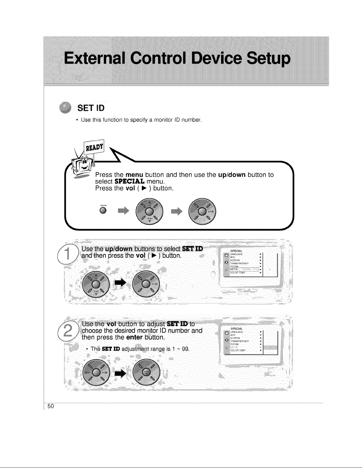
• Use this function to specify a monitor ID number.
Press the menu button and then use the up/down button to
select S_CIAL menu.
Press the vol (I_) button.
@
IIii1_
_i Use the vol button to adjust _'L" ID to/ choose the desired monitor ID number and
then press the enter button.
• The SET ID adjustment range is 1 ~ 99
_PEC A|
oJ
50
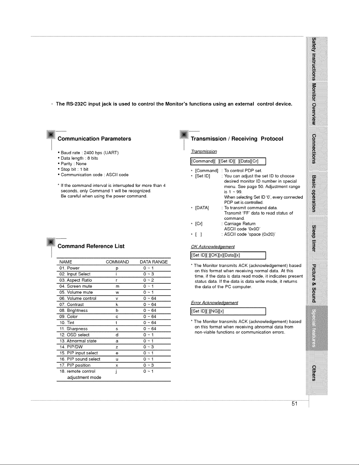
- The RS_232C input jack is used to control the Monitor's functions using; an external control device.
__Communication Parameters
" Baud rate : 2400 bps (UART)
' Data length : 8 bits
• Padty : None
' Stop bit : 1 bff
° Communication code : ASCL[ code
If the command interval is interrupted for more than 4
seconds only Command 1 will be recognized
Be c_efu_ when using the power command.
Reference List
NAME COMMAND DATA RANGE
01. Power p 0 "_1
02. input Seine1 i 0 _ 3
03 Aspect Ratio r O _ 2
04 Screen mute m 0 -_ 1
05. Volume mute w 0 -_ 1
06 Volume control v O _ 64
07. Contrast k O _ 64
08 Brightness b 0 -_ 64
09 Co,or c O '_ 64
t0. Tint t 0 _ 64
11 Sharpness s 0 _ 64
12_ OSD select d 0 _ 1
13 Abnormal state a O _ 1
14, PIP/DW z 0 _ 3
15 PiP input sel_: e 0 -- 1
16. PIP sound select u 0 -- 1
17. PIP position x O - 3
18 remote control j 0 _ 1
adjustment mode
Transmission ! R_eiving Prot_ol
Tra_mission
I[Command][ ][Set ID][ ][Data][Cr]
. [Command 1
* [Set ID]
* [DATA]
[Cr]
*[]
I
To control PDP set.
You can adjust the set ID to dloose
desired monitor [D number in special
menu. See page 50. Adjustment range
is I ~ 99
When selectJr,_j Set _D '0' every connected
PDP set is contro4_,
To transmit command data,
Transmit 'FF data to read status of
command
Carriage Ret:urn
ASCII code '0x0D'
ASCII code 'space (Ox20)'
OK AcknowJedaement
i[Set 1D][ :][OK][xl[Da'_3][x] I
The Monitor transmits ACK (acknowledgement) based
on this format when receiving normal data At this
time, if tl'_e data is data read m_e, it indicates present
status data, If the data is data wdte mode it returns
the data of the PC computer
Erro_ Ack_wledgemeet
I[settD][:][NG][x]
* The Monffor transmits ACK (acknowledgement) based
on this format when receiving abnormal data from
non-viable functions or communication errors.
iiiiiiii_!i!ii!ii!i_!i_ii_%_i_i_i!i;!i;!i;iii_ii:i_ij_i
iiii_!;!_;_!_;_i_!_!_!i_!_!_!!_!!_!!_!!_!!_!!_!!_!!_!!_!!_!!_!!_!!_!!_!!_!!_!i_
iiiiii!!!!iZi
51
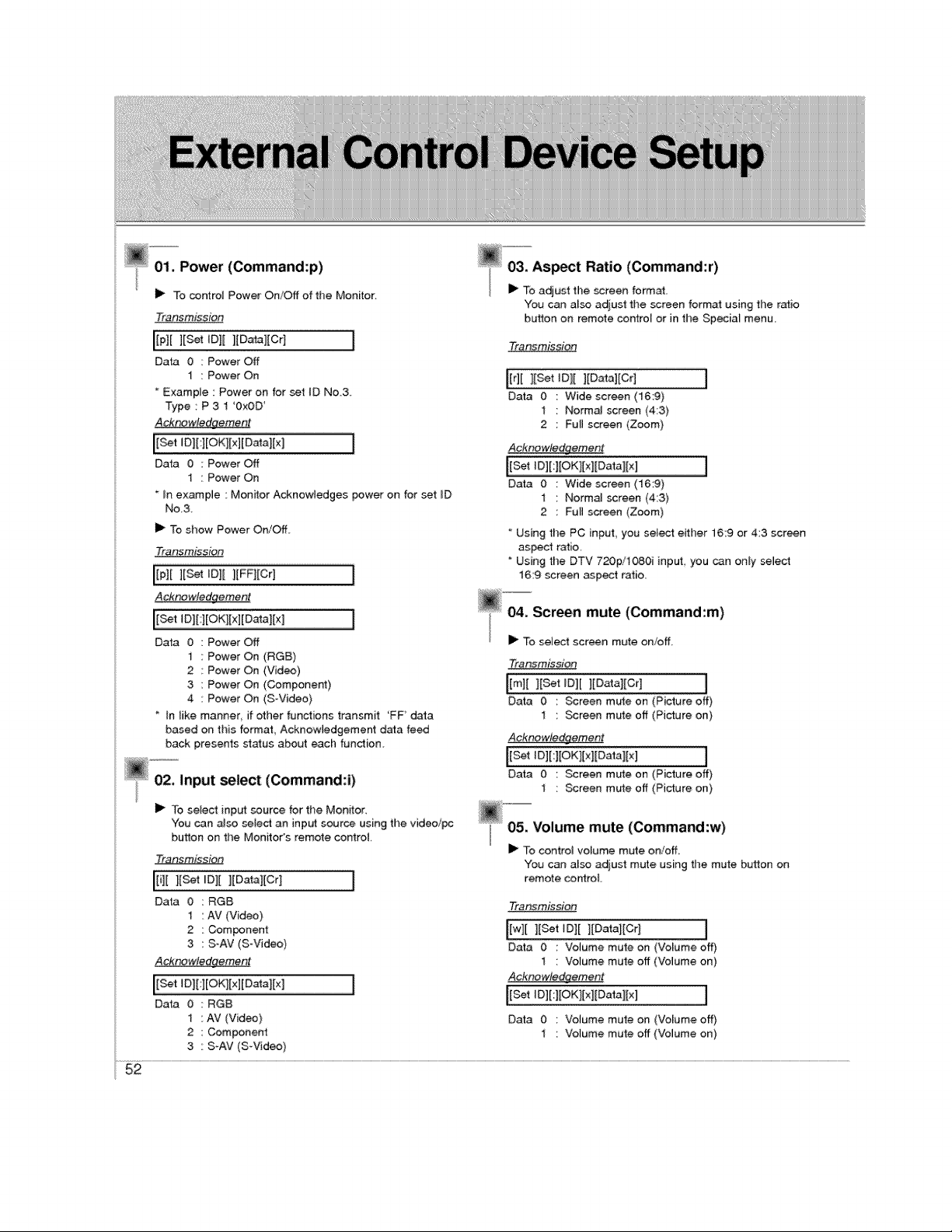
01. Powe, (Command:p)
i_ Tocontrol PowerOn/Offof the Monitor.
Transmission
[[p][ ][_t tD][ ][Data][Cr] [
Data 0 Power Off
1 : Power On
Example : Power on for set tD No3,
Type : P 3 1 '0x0D
Acknowledgement
I
Data 0 :Power Off
1 : Power On
* _n example : Monitor Acknowledges power on for set iD
No3
I_ % show Power On/Off
Transmissioe
[[p][ ][_t ID][ ][FF][Cr] I
Acknowledgement
Data 0 Power Off
1 Power On (RGB)
2 Power On (Video)
3 Power On (Component)
4 Power On (S-Video)
tn tike manner if other functions transmit 'FF data
based on this format, Acknowledgement d_a feed
back presents status about each function
select (Command:i)
I_ To select input source for the Monitor
"You can also select an input source using the video/pc
button on the Monitor's remote control
Tfan_;mJssio_
l[sot OlI][Oat !!Cr! [
Data 0 :RGB
1 : AV (Video)
2 : Component
3 : S-AV (S Video)
Acknowledqement
Data 0 RGB
1 AV (Video)
2 Component
3 S-AV (S-Video)
You can also adjust the screen format using ti_e ratio
button on remote contro_ or in the Special menu,
Transmission
li;iili:s t lIDatal Crl J
Data 0 : Wide screen (16:9)
1 " Normal screen (4:3)
2 : Full screen (Zoom)
Acknowledgement
Data 0 : Wide screen (16:9)
1 : Normal screen (4:3)
2 : Full screen (Zoom)
Using the PC input, you se_e_ either 16:9 or 4:3 screen
aspe_ ratio,
Using the DTV 720p/1080i input you can only select
16:9 screen aspect ratio,
04. Screen mute (Command:m)
i_ To select screen mute on/off
Transmission
limH set,o Epatchier1 I
Data 0 : Screen mute on (Picture off)
1 : Screen mute off (Picture on)
Acknowledgement
Data 0 : Screen mute on (Picture off)
1 : Screen mu_e off (Picture on)
_"_'05,= Volume mute (Command :w)
I_ To control volume mute on!off,
You can a_so adjust mute using the mute button on
remote conlroL
Transmission
# I
[w][ ][Set _D][ ][Data;[Cr]
r ........" ......-_ .......... .................................,
Data 0 : Votume mute on (Volume off)
I : Volume mute off (Volume on)
Acknowledge_nent
I
Data 0 : Votume mute on (Volume off)
1 : Volume mute off (Volume on)
52
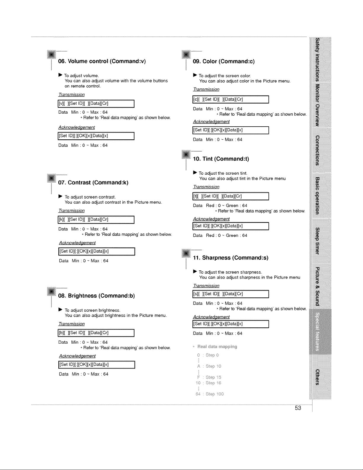
06. Volume control (Command:v)
II_ To adjust volume.
You can also adjust volume with the volume buttons
on remote controL
Tra nsmission
[[v][ ][Set ID][ ][Datal[Cr] ]
Data Min 0~Max:64
* Refer to 'Rea_ data mapping' as shown below.
_cknewle_eme#t
[Set ID][:][OK][x][Da_][x]
Data Min_0 _ Max:64
_"071" Contrast (Command:k)
I_ To adjust screen contrast.
You can _so adjust contrast in time Picture menu.
Transmission
Ilk][ ][Set IDI[ ][Datal[Cr ] ]
Data Min ::0 -_ Max : 64
* Refer to 'Real data m@t0ing' as shown below.
_cknowtedgement
I
Data Min : 0 ._Max : 64
@ _'_ Brightness (Command:b)
]1_ To adjust screen brigl_ness.
You can also adjust brigl_ness in the Picture menu
Transmission
I[b][ ][Set ID][ ][Data][Cr_ I
Data Min:0_Max:64
, Refer to 'ReaJ data mappin 9' as shown below.
Acknowledgement
Data Min:0-_Max:64
09, Color (Command:c)
II_ To adjust the screen color.
You can also adjust color in the Picture mena
Transmission
[[c][ l[Set IDI[ ][Datal[Crl ]
Data Min:0.-Max:64
Refer to 'Real data ma#ping' as shown below.
Acknowledgement
[[Set tD][:l[OK][xl[Data][x ] ]
Data Min:0 - Max:64
@-'10. Tint (Command:t)
]1_ To adjust the screen tint
You can a_so adjust tint in the Picture menu
Tran_mis_sOp
I[t][ ][Set ID][ l[Data][Cr] [
Data Red : 0 -_ Green : 64
Refer to 'Real data mapping' as shown betow.
_cknowledgement
[[Set tD][:][OK][x][Data][x I ]
Data Red:0_Green:64
11. Sharpness (Command:s)
I_ To adjust the screen sharpness.
You can aJso adjust sharpness in the Picture menu
TransmissiOn
[Is][ ][Set IDI[ ][Datal[Crl J
Data Min:0~Max:64
* Refer to 'Real data mapping _as shown below.
_qknowledgeme_nt
IEset'0tU O lE l Oatal I
Data Min:O _ Max:64
0 ;:s,p 0
A C;t®p O
_:_,:s f:!®p sO0
i_;_i!i!i!i!i!i!i!i!i!i!i!i!i!i!i!i!i!i!i_:@i
iii_ii_i!i!ii!ii!ii!ii!ii!ii!ii!ii!ii!ii!ii!ii!ii!ii!ii!ii!ii!i_!iiiiiii!!il
iii_:;_i_i_i_i_i_i_i_i_i_i_i_i_i_i_i_i_i_i!_!_i_i_i_i_i_i_i!
iiiii_i_i_ii_ii_i!_i_i_i_i_i_i_i_i_i_i!_i_i_i_i_i_i_i_i_!i;!_;!i_i
53
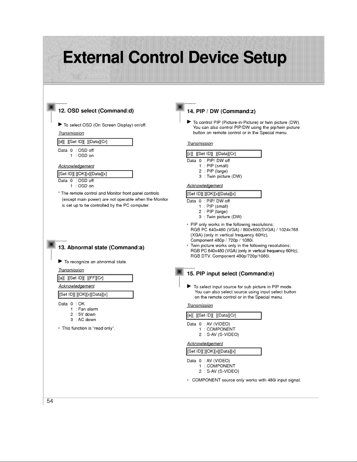
@"_;"_OSD select (Command:d)
I_ To select OSD (On _reen Display) oniofL
Transmission
[[d][ ][Set ID][ ][Data][Cr] [
Data 0 :OSDoff
1 : OSD on
Acknowledgement
[[s_tIol[ l{OKlI×]IOatal[×l [
Data 00SD off
1 : OSD on
" The remote control and Monitor front pane[ corfro_s
(except main power) are not operable when the Monitor
is set up to _ controlled by the PC computer,
I_ To recognize an abnormal state
Traosmission
[[a][ l[Set tDI[ ][FFltCr] [
_cknow,!ed_me_t
IEset'DIHEo'H×PotalE*II
Data 0 :OK
1 : Fan atarm
2 : 5V down
3 : AC down
* This function is "read only",
_""14"""PIP_ /DW (Command'z)
I_ To control PIP (Picture-in-Picture} or twin picture (DW).
You can also control PtPiDW using the pip/twin picture
button on remote control or in the Special menu
Transmission
[[z][ ][set [O|[ ][Data][Cr]
Data 0 :PIP/OWoff
I : PIP (small}
2 : PiP (large}
3 : Twin picture (DW)
Acknowledgement
[[Set ID][:][OK][xl[Data][x] ]
Data 0 PFP/OW off
1 PIP (small)
2 PiP (large)
3 Twin picture (DW)
PIP onty works in the foilowing resolutions:
RGB PC 640x480 (VGA) / 800x600(SVGA) / 1024x768
(XGA) (only in vertical frequency 60Hz)
Component 48Op / 720p / 1080i.
Twin picture works onty in the following resolutions:
RGB PC 640x480 (VGA} (onty in vertica_ frequency 60Hz),
RGB DTV, Compone_ 480p/720p/tO80L
@ "'15_PiP input select (Command:e)
II_ To select input source for sub picture in PIP mode.
You can a_so select source using input select button
on the remote control or in the Special menu,
Transmission
[[e][ ][Set ID][ ][Data][Cr]
Data 0 : AV (VIDEO)
t : COMPONENT
2 : S-AV (SoVlDEO)
Acknowledgement
Data 0 : AV (VIDEO)
1 : COMPONENT
2 : S-AV (S-VIDEO)
* COMPONENT source only works with 480i input signal
54
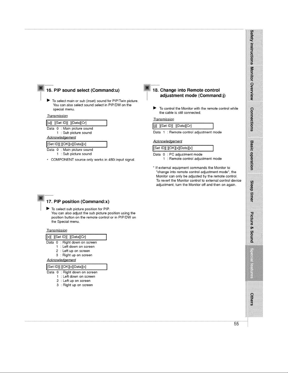
@ 'i'&_PIPsound _,_t (Command:u)
I_ To select main or sub (inset) sound for PiP/Twin picture,
You can aJso sele_ sound select in PIP/DW on the
s_ial menu.
Transmission
Data 0 : Main picture sound
t : Sub picture sound
A_wJedqement
I
DaB 0 : Main picture sound
1 : Sub picture sound
COMPONENT source only works in 480i input signal.
l& Change into Remote control
adjustment mode (Command:j)
I_ To controi the Monitor witl_ the remote control while
the cable is still conneded,
Transmission
l[j] [ ][Set ,Oil ][Data][Cr] I
Data 1 : Remote controt adjustment mode
Acknowte_ement
Data 0 : PC adjustment mode
1 : Remote control adjustment mode
* If externaJ equipment commands the Monitor to
"change into remote controt adiustment mode", the
Monitor can only be adjusted by the remote control
To revert the Monitor controt to external control device
adjustment turn the Monitor off and then on again
i i!i!i!i!ili!ili!iiiiiiiiiiiiiiiiii!iiii!i!ii!iliiiiiiiiii
iiiiiii_iii_ii_i_i_i!_i_i_i_i_i_!i_!i_!i_!i_!i_!i_!i_!i_!i_!i_!ii!i_i_ii_i_ii_
You can a4so adjust the sub picture position using the
position button on the remote controi or in PIPiDW on
the Special menu_
Transmission
_[x][ ][Set ID][ ][Data][Cr 1
Data 0 Right down on _reen
1 Left down on screen
2 Left up on screen
3 Right up on screen
AcknowJedgement
Data 0 : Right down on screen
1 : Left down on screen
2 : Left up on screen
3 ; Right up on screen
55

- Early malfunctions can be preven_d. Careful and regular cleaning can;extend the amount of
time you will have your new Monitor. Be sure to turn the power off and unplug the power
cord before you begin any cleaning.
i Cleaning the screen
_ake sure the eXCess water is off the screen, and then let
_!i!i!i!i!i!i!i!i!i!i!i!i!i!i!i!i!i!i!i!i!ii_ii!ii!ii!ii!ii!i!ii
Cleaning the cabinet
renot to use a wet cloth.
Extended absence
57
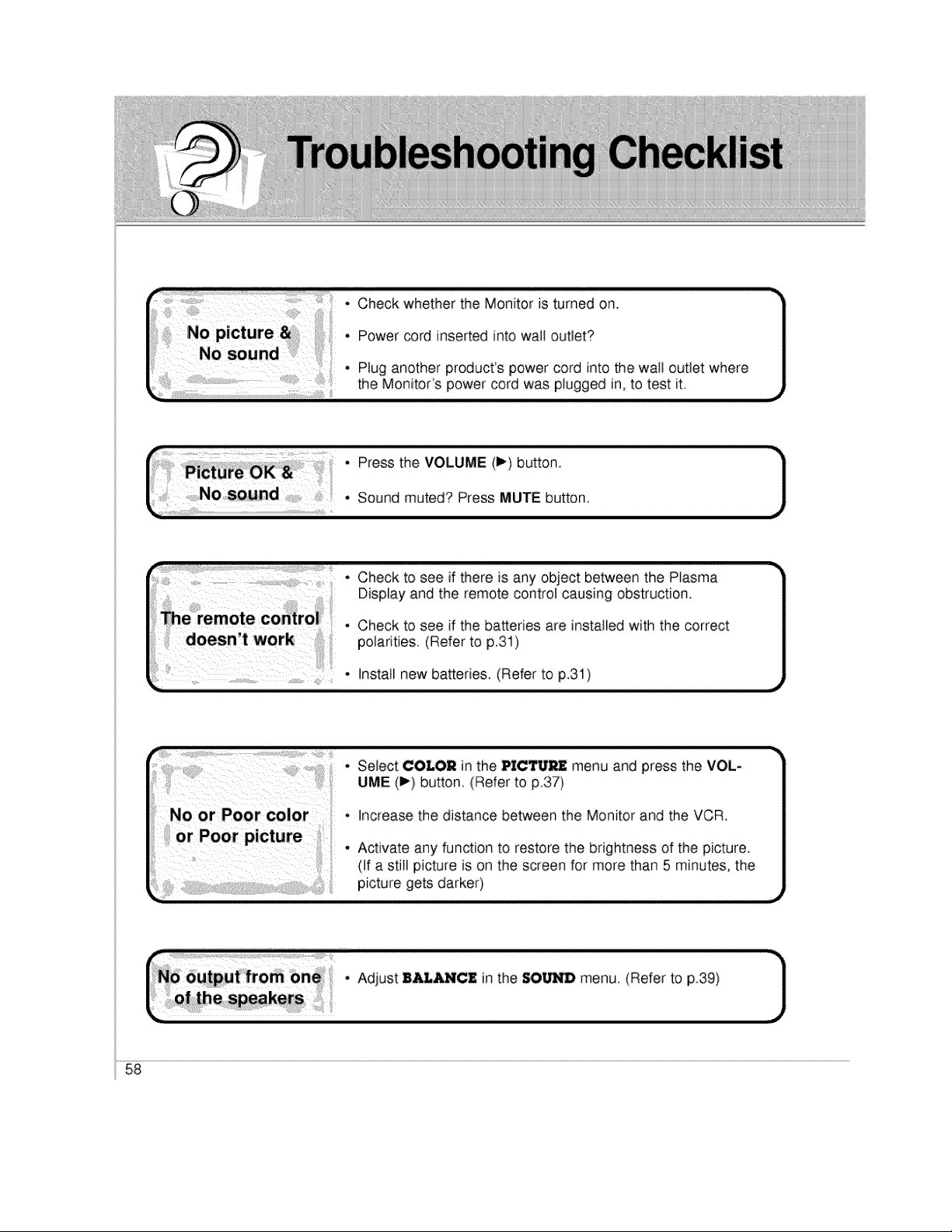
• Select COLOR in the PICTURE menu and press the VOL-
UME (I_) button. (Refer to p.37)
• Increase the distance between the Monitor and the VCR.
• Activate any function to restore the brightness of the picture.
(If a still picture is on the screen for more than 5 minutes, the
picture gets darker)
r.o_;_;i__. AO,ost. o,,o,he,OO-Omen°,_e,o_to_0, -]
58
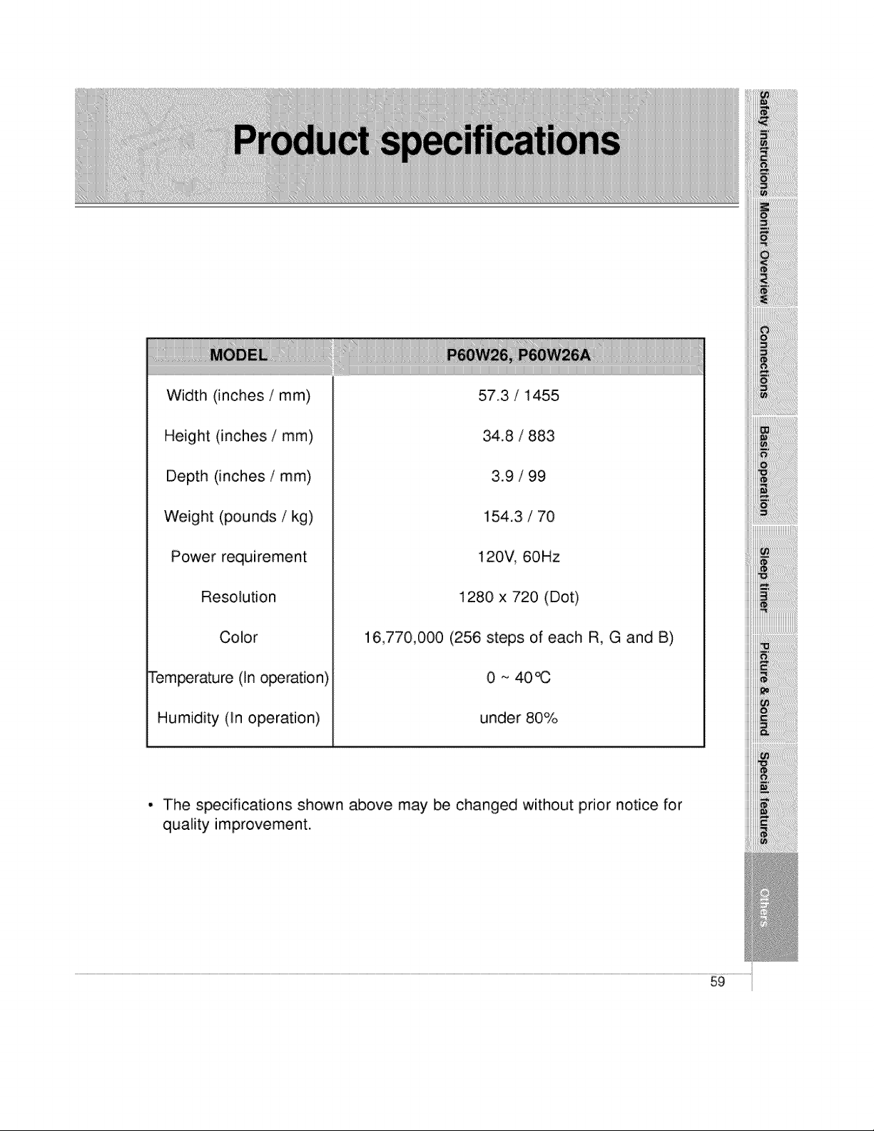
Width (inches / mm)
Height (inches / mm)
Depth (inches / mm)
Weight (pounds / kg)
Power requirement
Resolution
Color
Tem_rature (In operation)
Humidity (in operation)
57.3 / 1455
34.8 / 883
3.9 / 99
154.3 / 70
120V, 60Hz
1280 x 720 (Dot)
16,770,000 (256 steps of each R, G and B)
0 ~ 40_
under 80%
iiiiiiii_!i!ii!ii!i_!i_ii_%_i_i_i!ii!ii!iiiii_ii:i_ij_i
iiii_!_!!_!_!_i_!_!_!_!_!_!!_!!_!!_!!_!!_!!_!!_!!_!!_!!_!!_!!_!!_!!_!!_!!_!_!_
iiiiii!!!!iiiiiiiiiiiiiiiil
• The specifications shown above may be changed without prior notice for
quality improvement.
59

