Loading ...
Loading ...
Loading ...
o
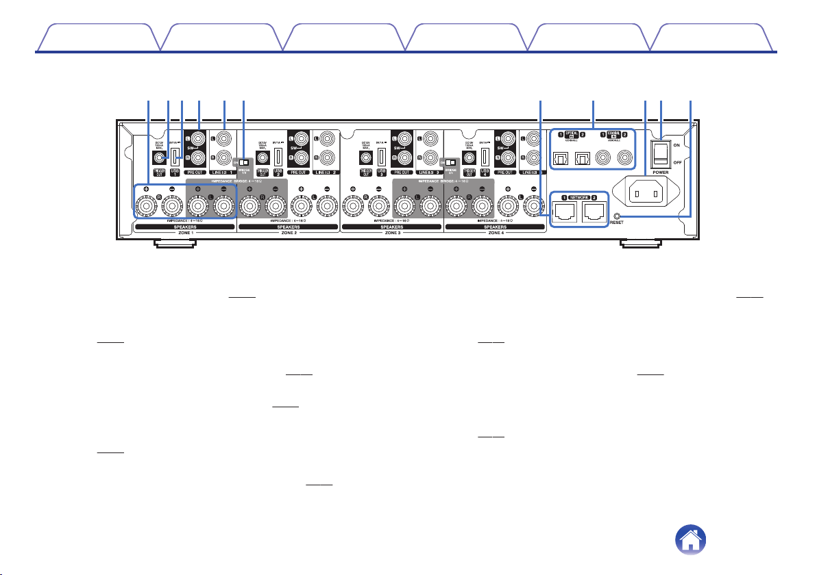
Back panel
.
q we r t y u i Q0o Q1
A
Speaker terminals (SPEAKERS)
Used to connect speakers. (v
p. 14)
B
TRIGGER OUT jack (TRIGGER OUT)
Used to connect devices equipped with a trigger function.
(v
p. 17)
C
USB Input (USB 5 V/1 A)
Used to connect USB storage devices. (v
p. 17)
D
Analog output (PRE OUT)
Used to connect external amplifiers. (v
p. 16)
E
Analog Input (LINE IN)
Used to connect devices equipped with analog audio outputs.
(v p. 18)
F
Bridge Mode Switch (BRIDGE)
Used to enable the amplifier bridge setting. (v p. 15)
G
NETWORK connector
Used to connect this unit to a wired Ethernet network. (v
p. 21)
H
Digital Input (OPTICAL IN/COAXIAL IN)
Used to connect devices equipped with digital audio outputs.
(v
p. 18)
I
AC inlet
Used to connect the power cord. (v
p. 20)
J
Master Power Switch (POWER)
K
RESET button
Various settings are reset to the factory default values.
(v
p. 55)
Contents Setup Use Troubleshooting Status LED Appendix
10
Loading ...
Loading ...
Loading ...