Loading ...
Loading ...
Loading ...
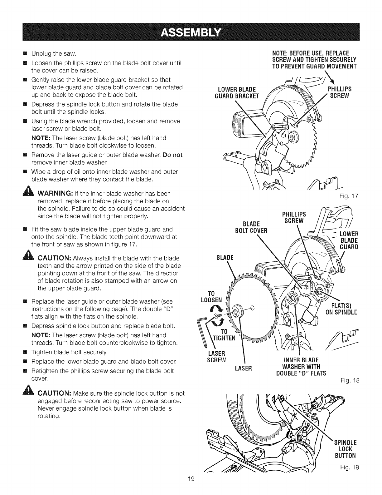
[] Unplugthesaw.
[] Loosenthephillipsscrewonthebladeboltcoveruntil
thecovercanberaised.
[] Gentlyraisethe lowerbladeguardbracketsothat
lowerbladeguardandbladeboltcovercanberotated
upandbackto exposethebladebolt.
[] Depressthespindlelockbuttonandrotatetheblade
boltuntilthespindlelocks.
[] Usingthe bladewrenchprovided,loosenandremove
laserscrewor bladebolt.
NOTE:Thelaserscrew(bladebolt)haslefthand
threads.Turnbladeboltclockwiseto loosen.
[] Removethelaserguideorouterbladewasher.Donot
removeinnerbladewasher.
[] Wipeadropof oilontoinnerbladewasherandouter
bladewasherwheretheycontacttheblade.
,_ WARN(NG: If the inner blade washer has been
removed, replace it before placing the blade on
the spindle. Failure to do so could cause an accident
since the blade will not tighten properly.
[] Fit the saw blade inside the upper blade guard and
onto the spindle. The blade teeth point downward at
the front of saw as shown in figure 17.
,_ CAUTION: Always install the blade with the blade
teeth and the arrow printed on the side of the blade
pointing down at the front of the saw. The direction
of blade rotation is also stamped with an arrow on
the upper blade guard.
[] Replace the laser guide or outer blade washer (see
instructions on the following page). The double "D"
flats align with the flats on the spindle.
[] Depress spindle lock button and replace blade bolt.
NOTE: The laser screw (blade bolt) has left hand
threads. Turn blade bolt counterclockwise to tighten.
[] Tighten blade bolt securely.
[] Replace the lower blade guard and blade bolt cover.
[] Retighten the phillips screw securing the blade bolt
cover.
,_ CAUT(ON: Make sure the spindle lock button is not
engaged before reconnecting saw to power source.
Never engage spindle lock button when blade is
rotating.
BLADE
BOLTCOVER
BLADE
TO
LOOSEN
TO
LASER
SCREW
LASER
NOTE:BEFOREUSE, REPLACE
SCREWANDTIGHTENSECURELY
TO PREVENTGUARDMOVElVlENT
\
PHiLLiPS
SCREW
Fig. 1 7
PHILLIPS
SCREW
LOWER
BLADE
GUARD
FLAT(S)
ONSPINDLE
INNERBLADE
WASHERWiTH
DOUBLE"D" FLATS
Fig. 18
19
SPINDLE
LOCK
BUTTON
Fig. 19
Loading ...
Loading ...
Loading ...