Loading ...
Loading ...
Loading ...
KNOWYOUR COMPOUND MITER SAW
See Figure 1.
The safe use of this product requires an understanding of
the information on the tool and in this operator's manual
as well as a knowledge of the project you are attempting.
Before use of this product, familiarize yourself with all
operating features and safety rules.
10 in. BLADE
A 10 in. blade is included with your compound miter saw.
It will cut materials up to11-1/2 in. wide, depending upon
the angle at which the cut is being made.
15 AMP MOTOR
Your saw has a powerful 15 amp belt-driven motor with
sufficient power to handle tough cutting jobs. It is made with
all ball bearings, and has externally accessible brushes for
ease of servicing.
BEVEL LOCK KNOB
The bevel lock knob securely locks your compound miter
saw at desired bevel angles. A positive stop adjustment
screw has been provided on each side of the saw arm.
These adjustment screws are for making fine adjustments
at 0° and 45°.
BEVEL STOP PIN
The bevel stop pin has several positions:
1. Override (pin pulled completely out)
2. The 0° - 48 ° position for crown molding (pin pushed in)
3. Stops at 33.9 ° and 45 °
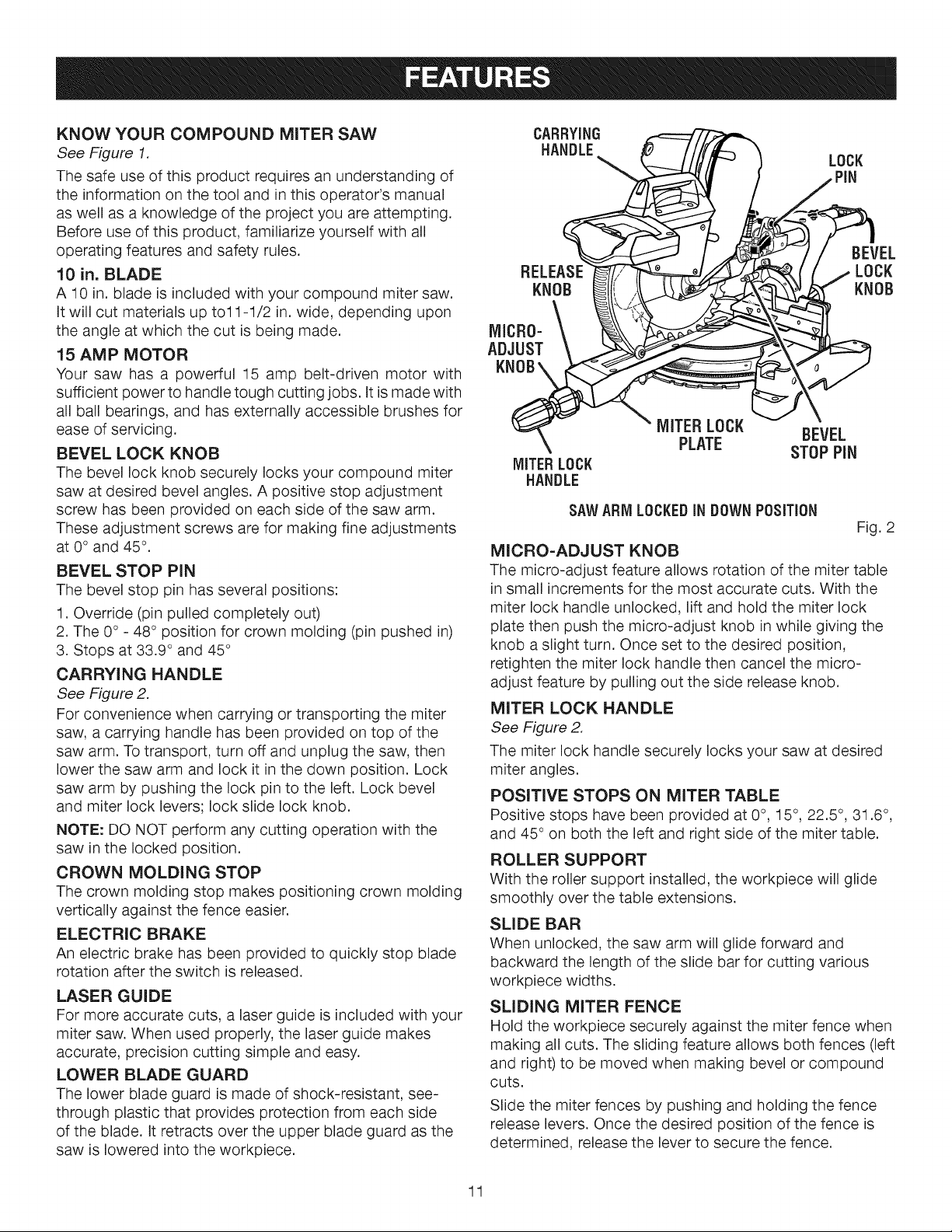
CARRYING HANDLE
See Figure 2.
For convenience when carrying or transporting the miter
saw, a carrying handle has been provided on top of the
saw arm. To transport, turn off and unplug the saw, then
lower the saw arm and lock it in the down position. Lock
saw arm by pushing the lock pin to the left. Lock bevel
and miter lock levers; lock slide lock knob.
NOTE: DO NOT perform any cutting operation with the
saw in the locked position.
CROWN MOLDING STOP
The crown molding stop makes positioning crown molding
vertically against the fence easier.
ELECTRIC BRAKE
An electric brake has been provided to quickly stop blade
rotation after the switch is released.
LASER GUIDE
For more accurate cuts, a laser guide is included with your
miter saw. When used properly, the laser guide makes
accurate, precision cutting simple and easy.
LOWER BLADE GUARD
The lower blade guard is made of shock-resistant, see-
through plastic that provides protection from each side
of the blade. It retracts over the upper blade guard as the
saw is lowered into the workpiece.
CARRYING
HANDLE_ LOCK
RELEASE_J_ _ ( / ., LOCK
Nj MICR0"\ °
MITERLOCK BEVEL
PLATE STOPPiN
MITERLOCK
HANDLE
SAWARM LOCKEDIN DOWN POSiTiON
Fig. 2
MICRO-ADJUST KNOB
The micro-adjust feature allows rotation of the miter table
in small increments for the most accurate cuts. With the
miter lock handle unlocked, lift and hold the miter lock
plate then push the micro-adjust knob in while giving the
knob a slight turn. Once set to the desired position,
retighten the miter lock handle then cancel the micro-
adjust feature by pulling out the side release knob.
MITER LOCK HANDLE
See Figure 2.
The miter lock handle securely locks your saw at desired
miter angles.
POSITIVE STOPS ON MITER TABLE
Positive stops have been provided at 0 °, 15 °, 22.5 °, 31.6 °,
and 45 ° on both the left and right side of the miter table.
ROLLER SUPPORT
With the roller support installed, the workpiece will glide
smoothly over the table extensions.
SLIDE BAR
When unlocked, the saw arm will glide forward and
backward the length of the slide bar for cutting various
workpiece widths.
SLIDING MITER FENCE
Hold the workpiece securely against the miter fence when
making all cuts. The sliding feature allows both fences (left
and right) to be moved when making bevel or compound
CutS.
Slide the miter fences by pushing and holding the fence
release levers. Once the desired position of the fence is
determined, release the lever to secure the fence.
11
Loading ...
Loading ...
Loading ...