Loading ...
Loading ...
Loading ...
Page 27 of 53
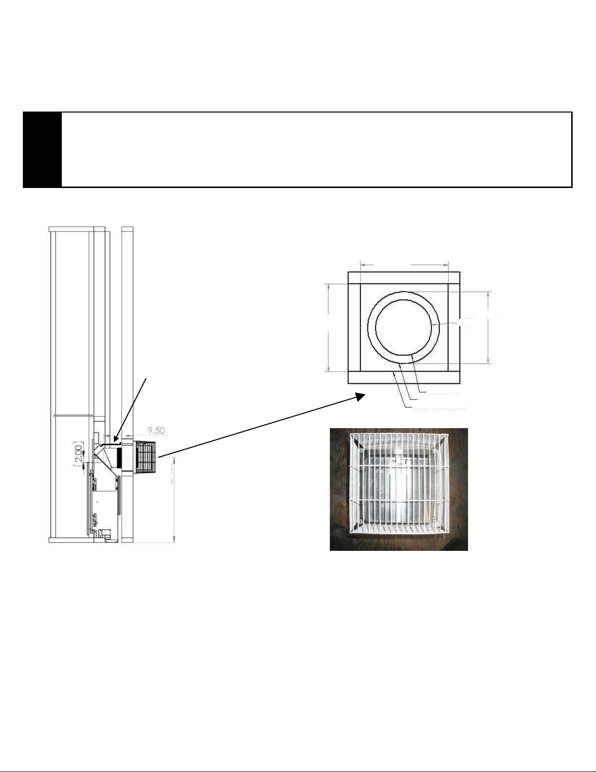
Horizontal Wall Vent Terminations
The position of the horizontal vent termination must be positioned in such a way as to meet all local building
codes. Attach the correct length of pipe. Mark the center line of the pipe facing the wall (allowing for a 1/4”
rise per foot of horizontal, example 10 ft of horizontal would require a rise of 2.5”).
NOTE
ALLOWING THE VENT PIPE TO SLOPE DOWN TOWARDS THE VENT TERMINATION COULD
CAUSE POOR COMBUSTION AND/OR HIGH TEMPERATURES THAT MAY PRESENT A FIRE
HAZARD.
PERMETTRE LA tuyau de ventilation vers descendent vers la sortie de ventilation POURRAIT
PROVOQUER une mauvaise combustion et / ou de températures élevées qui peuvent présenter
des risques d'incendie.
SIDE VIEW OF
TERMINATION
VENT
VIEW OF SAFETY CAGE
Mark a 8” x 8” square around the center mark (inside dimensions). Cut and frame the exterior wall to accept
the wall thimble. Install the wall thimble, on the inside of the exterior wall, shield using wood screws.
Attach the venting to the termination using sheet metal screws. To install the termination attach the 3” exhaust
to the termination and fasten with 3 #8 x ½” hex head sheet metal screws then attach the 6” vent to the
termination and fasten with 4 #8 x ½” hex head sheet metal screws, be sure that the flex vent overlaps the
termination collars a minimum of 2”. Then attach the termination to the exterior wall using four wood screws
through the holes in the corner of the vent terminal.
The next step is to apply a bead of mil-pac or RTV 106 to top of the 3” exhaust collar on the unit and attach the
3” vent using screws (as described above), finally apply a bead of mil-pac or RTV 106 to top of the 6” vent and
attach (as described above).
8.00”
HEAT DEFLECTOR MUST
BE INSTALLED FOR
MINIMUM 38” INTERNAL
CEILING
13.00”
8.00”
Ø 6.00”
Ø 8.00”
8 X 8 MIN OPENING
WALL THIMBLE 8"
OUTER PIPE 6”
26.59
Loading ...
Loading ...
Loading ...