Loading ...
Loading ...
Loading ...
Page 20 of 53
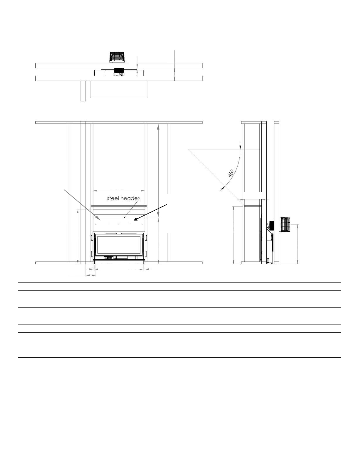
3.3.2 MINIMUM CLEARANCES / DÉGAGEMENTS
Clearances are in accordance with local installation codes and the requirements of the gas supplier.
**
The mantel placement chart on this page illustrates the allowable mantel sizes and placements. The 45 degree angle can be
used to determine the allowable mantel size based on the elevation above the units upper trim.
Les dégagements sont en conformité avec les codes d'installation locaux et les exigences du fournisseur de gaz.
** Le tableau placement manteau sur cette page illustre les dimensions et les emplacements admissibles cheminée. L'angle de
45 degrés peut être utilisé pour déterminer la taille permise manteau repose sur l'élévation au-dessus de la garniture unités
supérieures.
A = 40”
TO INTERNAL CEILING
B = 1”
TO INTERNAL SIDE COMBUSTIBLES (0” TO STANDOFFS)
C = 8.75”
TO BACK WALL FROM FRONT OF UNIT (0” TO STANDOFFS)
D = 6”
TO SIDE WALL
E = 32.5”
FROM BOTTOM OF FIREPLACE TO COMBUSTIBLE MATERIAL
F=36”
MINIMUM CEILING HEIGHT FROM TOP OF UNIT
G=40”
MINIMUM FROM BOTTOM OF FIREPLACE TO MANTLE
(SEE DIAGRAM)
0”
BASE OF UNIT TO FLOOR
0.75”
REAR OF FIREPLACE TO BACK WALL
E 32.50”
36.00”
B 1.00”
B 1.00”
0.75”
C 8.75”
A 40.00”
D 6.00”
G 40.00”
12.00”
26.59”
F 36.00”
NON-
COMBUSTIBLE
BOARD 9.5” X 36”
SUPPLIED BY
MANUFACTURER
SEE
MANUFACTURER
NOTES
PREVIOUS PAGE
Heat baffle must be
fixed to non-
combustible board on
installation. (see
diagram on page 18.
Loading ...
Loading ...
Loading ...