
Loading ...
Loading ...
Loading ...
Page 7
INSTALLING INTERIOR ASSEMBLY
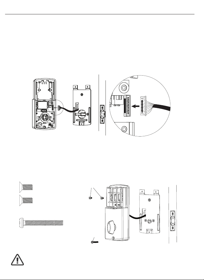
11. ATTACH THE CONTROL WIRE TO THE INTERIOR ASSEMBLY
a. Use care to attach the Control Wire male plug to the Interior Assembly female
socket connector (Figure 11a).
b. Do not force the Control Wire male plug into the Interior Assembly female
socket connector (Figure 11b).
c. The Control Wire male plug has two alignment tabs on the smooth side of the
plug which is the top of the plug (Figure 11c).
d. The Control Wire male plug is inserted with the smooth side up into the Interior
Assembly female socket connector (Figure 11d).
12. ATTACH THE INTERIOR ASSEMBLY TO DOOR
a. Position the Interior Assembly over the tailpiece and push the Interior Assembly
against the door (Figure 12a).
b. Using two 5/16” (8mm) screws and one 1” (25mm) screw, attach
the Interior Assembly to the Mounting Plate. DO NOT OVER TIGHTEN SCREWS
(Figure 12b).
5/16” (8mm) screws
1” (25mm) screw
NOTE: Lock and unlock using Interior Knob to see if the
latch is opening and closing easily.
Figure 12a-b
Figure 11a-d
Loading ...
Loading ...
Loading ...