
Loading ...
Loading ...
Loading ...
Page 2
NOTE: For installation on doors with pre-drilled holes skip to page 4.
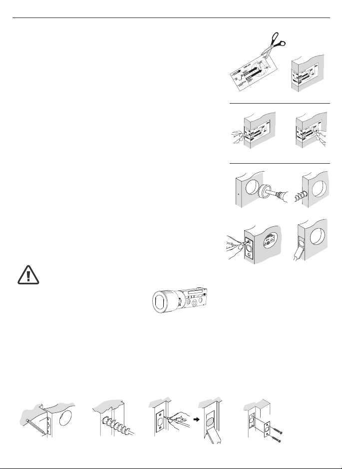
1. TEMPLATE
a. Cut out template printed on page 15 & 16 of this Manual
(Figure 1a).
b. Fold template and place on door 36” (915mm) from
the ground as marked (Figure 1b).
2. MARK THE DOOR FOR DRILLING
b. Mark center hole on door edge through guide on
template for 1” (25mm) latch bolt (Figure 2a).
a. Mark center hole on door face through guide on
template for 2-3/8” (60mm) or 2-3/4” (70mm)
backset (Figure 2b).
3. DRILL AND CHISEL DOOR
a. Drill 2-1/8” (54mm) hole through door face as marked
for lock set (Figure 3a).
b. Drill 1” (25mm) hole in center of door edge for
Deadbolt Latch Assembly (Figure 3b).
c. Insert Deadbolt Latch Assembly in hole keeping it
parallel to face of door. Mark outline and remove latch
(Figure 3c).
d. Chisel 1/8” (3mm) deep or until latch face is ush
with door edge (Figure 3d).
4. MARK AND DRILL DOOR JAMB
a. Mark center hole on edge of jamb even with the center of the Latch Bolt on door
edge. (Figure 4a).
b. Drill 1” (25mm) hole 1-3/16” (30mm) deep in door jamb on center mark
(Figure 4b).
c. Outline outside edges of Strike Plate (Figure 4c).
d. Chisel 1/8” (3mm) deep for Strike Plate or until ush (Figure 4d).
e. Install Strike Plate using two 3/4” (19mm) screws provided (Figure 4e).
PREPARE DOOR AND JAMB
Figure 4a Figure 4b
Figure 4c Figure 4e
Figure 4d
NOTE: For Drive in Latch, drill hole size indicated on template and press
until it is ush with door edge.
U
P
Figure 1a
Figure 2a Figure 2b
Figure 3a
Figure 3c
Figure 1b
Figure 3b
Figure 3d
Loading ...
Loading ...
Loading ...