Loading ...
Loading ...
Loading ...
SERVICE AND ADJUSTMENTS
LINE R--E-P-LAC EMEN'r ........
WARNING:
TRIMMER HEAD PARTS THAT ARE
CHIPPED, CRACKED, BROKEN, OR DAM-
AGED IN ANY OTHER WAY CAN FLY
APART AND CAUSE SERIOUS INJURY.
DO NOT USE. REPLACE DAMAGED
PARTS BEFORE USING THE UNIT.
THE LINE SAVER MUST BE INSTALLED
ONLY FROM THE INSIDE OFTHE HUB. IF
INSTALLED ON THE OUTSIDE OF THE
HUB, THE LINE SAVER CAN FLY OFF
AND BECOME A DANGEROUS MISSILE.
USE ONLY .080" DIAMETER GOOD
QUALITY LINE. NEVER USEWIRE, ROPE,
STRING, ETC.
THE LOCK RING MUST ENGAGE ALL
FOUR CATCHES WHEN REINSTALLED
OR THE LOCK RING WILL FLY OFF AND
CAUSE SERIOUS INJURY.
USE ONLY SPECIFIED SEARS REPLACE-
MENT PARTS. USE OF OTHER BRANDS
OF REPLACEMENT PARTSCAN CAUSE
DAMAGE TO YOUR UNIT OR INJURY TO
THE OPERATOR OR OTHERS.
DAMAGE/INJURY CAUSED BY USE OF
ACCESSORIESIATTACHMENTS NOT
SPECIFICALLY RECOMMENDED BY
SEARS WILL NOT BE REIMBURSED.
IMPORTANT: ALWAYS CLEAN DIRT AND DEBRIS
FROM SPOOL AND HUB WHEN PERFORMING ANY
TYPE MAINTENANCE. IF LINE SAVER FALLS OUT,
REINSTALL IT FROM THE INSIDE OF THE TRIMMER
HEAD.
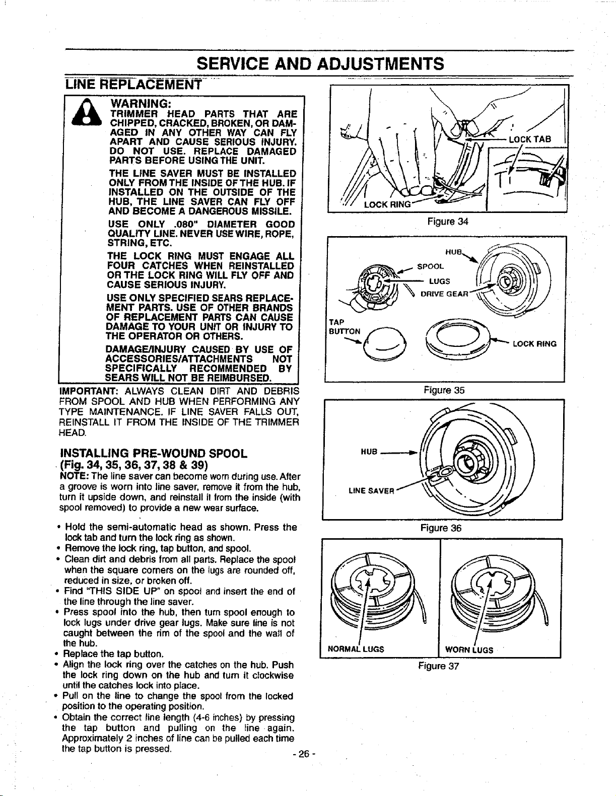
INSTALLING PRE-WOUND SPOOL
(Fig. 34, 35, 36, 37, 38 & 39)
NOTE: The linesaver canbecome wornduring use.After
a groove is worn into line saver, removeit from the hub,
turn it upside down, and reinstall il fromthe inside(with
spoolremoved) to provide a new wearsurface.
• Hold the semi-automatic head as shown. Press the
locktab and turnthe lockring as shown.
• Remove the lock ring,tap button,andspool.
• Clean dirt and debris from all parts.Replacethe spool
when the square corners on the tugs are roundedoff,
reduced insize, or brokenoff.
• Find "THIS SIDE UP" on spool and insertthe end of
the linethrough the linesaver.
• Press spool into the hub, then turnspool enough to
lock lugs under drive gear lugs. Makesure lineis not
caught between the rim of the spooland the wail of
the hub.
° Replacethe tap button.
• Alignthe lock ring over the catcheson the hub. Push
the lock ring down on the hub and turn it clockwise
untilthecatches lockintoplace.
• Pull on the line to change the spoolfrom the locked
positionto the operating position.
• Obtain the correct line length (4-6 inches)by pressing
the tap button and pulling on the Iine again.
Approximately2 inchesof line canbe pulled eachtime
the tap button is pressed. - 26 -
LOCK RING
Figure 34
TAP
DRIVE GEAR__
LOCK RING
Figure 35
NORMAL LUGS WORN LUGS
Figure 37
Figure 36
Loading ...
Loading ...
Loading ...