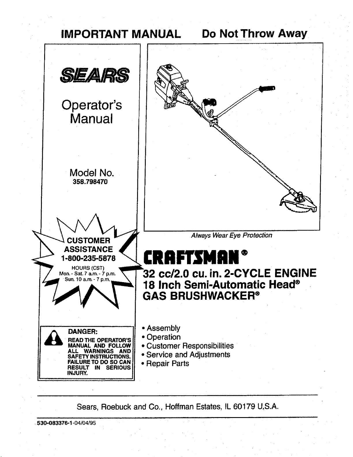
IMPORTANT MANUAL Do Not Throw Away
Operator's
Manual
Model No.
358.798470
CUSTOMER
ASSISTANCE
1-800-235-5878
DANGER:
READ THE OPERATOR'S
MANUAL AND FOLLOW
ALL WARNINGS AND
SAFETY INSTRUCTIONS.
FAILURE TO DO SO CAN
RESULT IN SERIOUS
INJURY.
Always Wear Eye Protection
®
cc/2.0 cu. in. 2-CYCLE ENGINE
18 Inch Semi-Automatic Head®
GAS BRUSHWACKER®
• Assembly
° Operation
• Customer Responsibilities
° Service and Adjustments
° Repair Parts
Sears, Roebuck and Co., Hoffman Estates, IL 60179 U_S.A.
530.083376-1-04/04/95
ii i tIJL
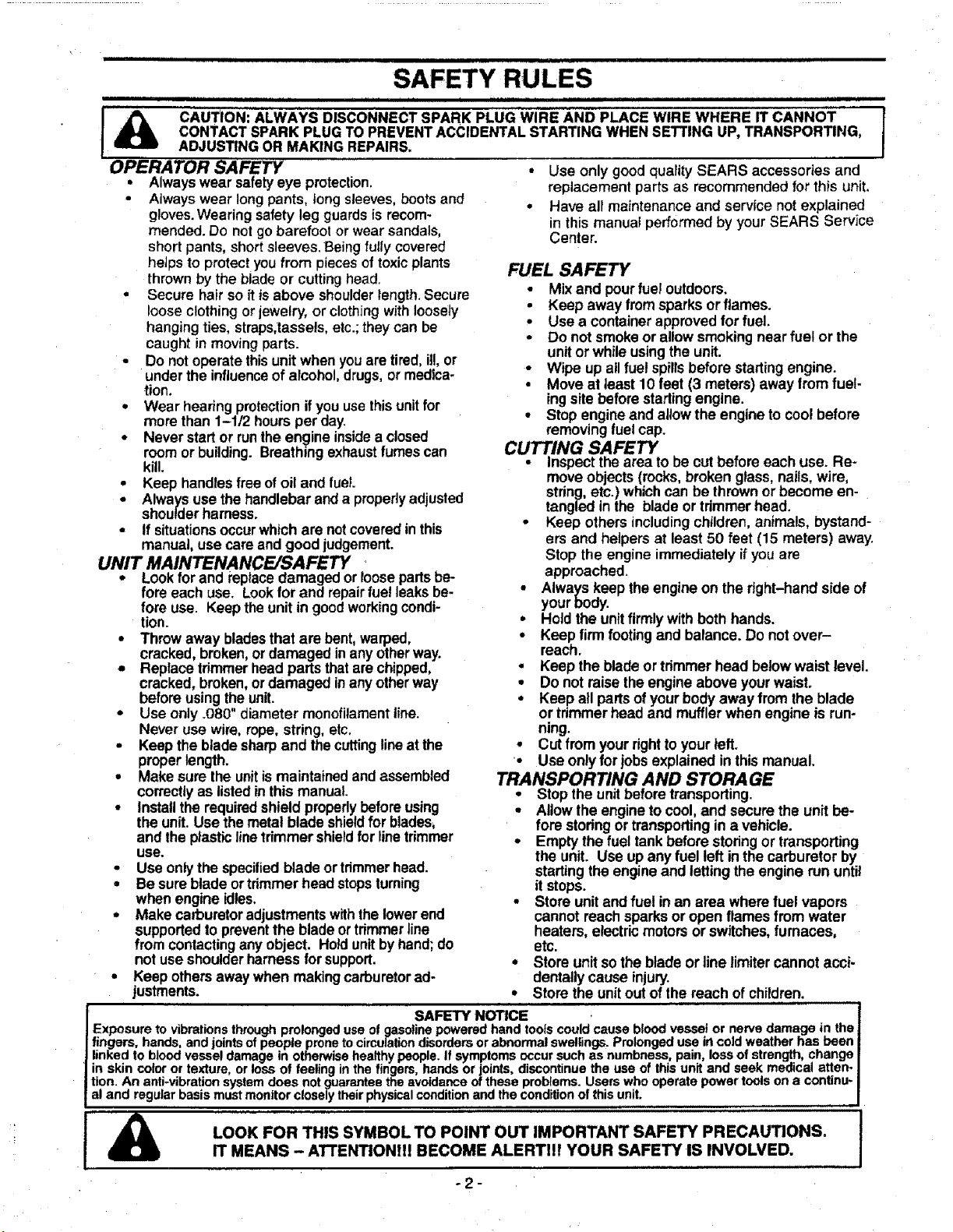
SAFETY RULES
cAUT|oNI ALWAYS D SCONNECT SPARK PLUG RE A........ I Wl ND PLACE WIRE WHERE IT CANNOT
CONTACT SPARK PLUG TO PREVENTACCIDENTALSTARTING WHEN SETTING UP, TRANSPORTING,
ADJUSTING OR MAKING REPAIRS.
OPERATOR SAFETY
• Alwayswear safetyeye protection,
• Always wear longpants, tongsleeves,bootsand
gloves.Wearing safety leg guardsis recom-
mended. Do notgo barefoot or wear sandals,
shortpants, shortsleeves.Beingfully covered
heJpsto protectyou from piecescf toxicplants
thrownby the bladeor cuttinghead.
• Secure hair soit isabove shoulderlength. Secure
looseclothingorjewelry, or clothingwithloosely
hangingties, straps,tassels,etc.;theycan be
caught in movingparts.
• Do not operatethisunitwhen youare tired,it!,or
underthe influenceof alcohol,drugs,or medica-
tion.
• Wear hearingprotectionifyou usethisunitfor
more than 1-1/2 hoursper day.
• Never startor runthe engine insideaclosed
roomor building. Breathingexhaustfumes can
kill.
• Keep handlesfree of oiland fuel
• Alwaysuse the handlebarand a properlyadjusted
shoulderharness.
• If situationsoccurwhichare notcoveredin this
manual, usecare and good judgement.
UNIT MAINTENANCE/SAFETY
• Lookfor and replacedamaged or loosepartsbe-
fore each use. Lookfor and repairfue!leaksbe-
fore use. Keep theunit in goodworkingcondi-
lion.
° Throw away bladesthat are bent,warped,
cracked, broken,or damaged inanyotherway.
• Replace trimmerhead parts thatarechipped,
cracked, broken,ordamaged inany otherway
beforeusing theunit.
° Use only.080" diameter monofilamentline.
Never use wire, rope,string, etc.
• Keep the bladesharpand thecuttinglineat the
properlength.
• Make sure the unitis maintainedand assembled
correctlyas listedinthis manual.
• Installthe requiredshield properlybefore using
the unit. Use themetal blade shieldfor blades_
and theplasticlinetrimmer shieldfor linetrimmer
use.
• Use onlythe specifiedbladeor trimmerhead.
• Be sure blade ortrimmerhead stopsturning
when engine idles,
• Make carburetoradjustmentswiththelowerend
supportedto preventthe blade ortrimmerline
from contactingany object. Hold unitbyhand;do
not useshoulderharnessfor support.
• Keep othersaway when makingcarburetorad-
justments.
• Use only goodquality SEARS accessories and
replacement parts as recommended for this unit.
• Have air maintenance and service not explained
in this manual performed by your SEARS Service
Center.
FUEL SAFETY
• Mix and pourfue!outdoors.
• Keep away fromsparks orflames.
• Use a containerapprovedfor fuel.
• Do not smokeor allowsmokingnear fuel or the
unitor whileusingthe unit.
• Wipe up all fuel spillsbefore startingengine.
• Move at least 10 feet (3 meters) awayfromfuel-
ingsitebeforestarlingengine.
• Stop engine and allowthe engine tocool before
removingfuel cap.
CUTTING SAFETY
• Inspectthe area tobe cutbefore each use. Re-
moveobjects(rocks,broken glass,nails,wire,
string,etc.)whichcan be thrownor become en-
tangled in the blade ortdmmer head.
• Keep others includingchildren,animals, bystand-
ers and helpers at least 50 feet (15 meters) away.
Stop the engine immediately if youare
approached.
• Always keep the engineon the right-hand side of
yourbody.
• Hold the unitfirmly with both hands.
• Keep firm footing and balance. Do not over-
reach.
• Keep the blade or trimmerhead below waist level.
• Do not raise theengine above yourwaist.
• Keep all partsofyour bodyaway from the blade
or trimmerhead and muffler when engine is run-
ning.
• Cut from your right to your left.
• Use only for jobs explained in this manual.
TRANSPORTING AND STORAGE
° Stop the unitbeforetransporting.
• Allowthe engine tocool, and secure the unit be-
fore storingor transportingin a vehicle.
• Emptythe fuel tankbefore storingor transporting
the unit. Use up any fuel left inthe carburetor by
startingthe engineand lettingthe engine rununtil
it stops.
• Store unitand fuel inan area where fuel vapors
cannotreach sparksor openflames from water
heaters,electricmotors or switches,furnaces,
etc.
• Store unitso the bladeor line fimiter cannot acci-
dentallycause injury.
• Store the unitout of the reach of children.
I SAFETY'NOTICE . .............
JExposure to vibrations through prolonged use of gasoline powered hand toots could cause blood vessel or nerve damage in the
I fingers, hands, and joints of people prone to circulation disorders or abnormal swel|ings. Prolonged use in cold weather haS been
| linked to blood vessel damage in otherwise healthy people. If symptoms occur such as numbness, pain, loss of strength, change
] in skin color or texture, or loss of feeling in the fingers, hands or joints, discontinue the use of this unit and seek medical a_en-
Itton. An anti-vibration system does not guarantee the avoidance of these problems. Users who operate power tools on a continu-
I al and regular basis must monitor closely their physical condition and the condition of this unit.
LOOK FOR THIS SYMBOL TO POINT OUT IMPORTANT SAFETY PRECAUTIONS.
IT MEANS - AI"FENTIONtll BECOME ALERTllf YOUR SAFETY IS INVOLVED.
"2-
I
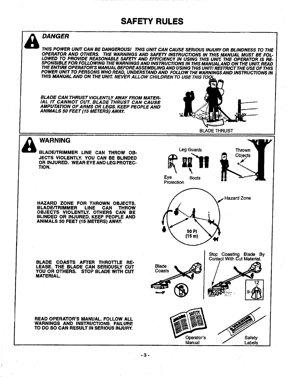
SAFETY RULES
DANGER
THIS POWER UNIT CAN BE DANGEROUS! THIS UNIT CAN CAUSE SERIOUS INJURYOR BLINDNESS TO THE
OPERATOR AND OTHERS, THE WARNINGS AND SAFETY INSTRUCTIONS IN THIS MANUAL MUST BE FOL-
LOWED TO PROVIDE REASONABLE SAFETYAND EFFICIENCY IN USING THIS UNIT. THE OPERATOR IS RE-
SPONSIBLE FOR FOLLOWING THE WARNINGSAND INSTRUCTIONS IN THISMANUALAND ON THE UNIT.READ
THEENTIRE OPERATOR'S MANUALBEFOREASSEMBLING AND USING THISUNIT! RESTRICT THE USEOF THIS
POWER UNIT TO PERSONS WHO READ, UNDERSTAND AND FOLLOW THEWARNINGSAND INSTRUCTIONS IN
THIS MANUAL AND ON THE UNIT. NEVER ALLOW CHILDREN TO USE THISTOOL.
BLADE CAN THRUST VIOLENTLY AWAY FROM MATER-
IAL IT CANNOT CUT. BLADE THRUST CAN CAUSE
AMPUTATION OF ARMS OR LEGS. KEEP PEOPLE AND
ANIMALS 50 FEET (15 METERS) AWAY.
WARNING
BLADE/TRIMMER LINE CAN THROW OB-
JECTS VIOLENTLY. YOU CAN BE BLINDED
OR INJURED. WEAR EYE AND LEG PROTEC-
TION.
BLADE THRUST
Leg Guards
Eye Boots
Protection
Thrown
HAZARD ZONE FOR THROWN OBJECTS.
BLADE/TRIMMER LINE CAN THROW
OBJECTS VIOLENTLY. OTHERS CAN BE
BLINDED OR INJURED, KEEP PEOPLE AND
ANIMALS 50 FEET (15 METERS) AWAY.
ird Zone
BLADE COASTS AFTER THROTTLE RE-
LEASE. THE BLADE CAN SERIOUSLY CUT
YOU OR OTHERS. STOP BLADE WITH CUT
MATERIAL.
READ OPERATOR'S MANUAL. FOLLOW ALL
WARNINGS AND INSTRUCTIONS. FAILURE
TO DO SO CAN RESULT IN SERIOUS INJURY.
Blade
Coasts
Manual
Stop Coasting Blade By
ContactWith Cut Material.
Safety
Labels
ill
-3-
CONGRATULATIONS on your purchase of a Sears
Craftsman Brushwacker. It has been designed,
engineered and manufactured to give you the best
possibledependability and performance.
Should you experience any problems you cannot easily
remedy, please contact your nearest Sears Service
Center/Department. Sears has competent, well trained
technicians and the proper tools to service or repair this
unil.
Please read and retain this manual. The instructions will
enable you to assemble and maintain your unit property.
Always observe the "SAFETY RULES."
MODEL NUMBER: 358.798470
DATE CODE/SERIAL NO.:
DATE OF PURCHASE:
THE MODEL AND SERIAL NUMBER WILL BE
FOUND ON THE PRODUCT.
YOU SHOULD RECORD BOTH SERIAL NUMBER
AND DATE OF PURCHASE AND KEEP IN A SAFE
PLACE FOR FUTURE REFERENCE.
MAINTENANCE AGREEMENT
A Sears Maintenance Agreement is available on this
product. Contact your nearest Sears Store for detaiIs.
CUSTOMER RESPONSIBILITIES
• Read and observe thesafety rules.
• Follow a regular schedule in maintaining,caring for,
and using your unit.
• Followthe instructionsunder"CustomerResponsibilities"
and "Storage" sectionsofthisOperator'sManual.
PRODUCT SPECIFICATIONS
,, ,,, ,,,,
CUTTING PATH
Trimmer Head ................... 18"
Weed Blade........_............. 8"
Brush Blade ...................... 8"
TRIMMER LINE ................... 080" Diameter
Monofilament Line
HEAD ROTATION............... Counterclockwise(foroperator)
ENGINE .............................. 32 cc, 2-cycle Air-Cooled
FUEL/OIL MIX RATIO......... 40:1 (3.2 oz. oilper
gallon gas)
iGNITION ............................ Solid State
IGNITION TIMING .............. Non-adjustable fixed
SPARK PLUG TYPE ........... Champion (RCJ-8Y)
SPARK PLUG GAP ............. 025" (.6mm)
MUFFLER ........................... Temperature Limiting
(not spark arresting)
ENGINE RPM ..................... Operating - 9000 Max.
SPECIAL NOTICE
ForusersonU.S.ForestLandandinsomestates,including
California (Public ResourcesCodes442 and443), Idaho,
Maine, Minnesota,New Jersey,Oregon,and Washington:
Certain internalcombustionengines operatedon forest,
brush, and/or grass-covered landsin theaboveareasare
required tobeequipped witha spark arrestor,maintainedin
effectiveworkingorder,or Ihe enginemustbeconstructed,
equipped, and maintainedfortheprevention offire.Check
withyourstateor localauthoritiesfor regulationspertaining
totheserequirements. Failuretofollowtheserequirements is
a violationofthetaw.Thisunitisnotfactory=equipped witha
sparkarrestor;however,a sparkarrestorisavailableas an
optionalpart.ff a sparkarrestorisrequiredinyourarea,con-
tactyourSEARS ServiceCentedDepartmentfor thecorrect
kit.
Manufactured under one or more _f the following U,S, patet_ls: 5,_,427: 5.367,988:
5,345.684; 5,343_831; 5.276.968: 5,269.665; 5.G_0,L_23: 4,940,028: 4,697,923: 4,852,258:
4,846,123; 4,84 t,929; 4.835,867; 4,825.548; 4,823,465; 4,819,742; 4,798,185: 4,508,068;
4,483,069; 4,451,983: 4,366,622:4.366.62114.352,243; 4,347,666: 4,L_0,200; 4.286,675;
4,236.312; 4,177,_61 ; 4,172.322; 4.167,812; 4,!62,575; 4,161,820; 4,122.653: 4,104,797:
Re,32.266; D344,088; D324.051: 1_304.196; 0276,!60. Other U,S. and foreign patents
periling.
FULL ONE YEAR WARRANTY ON CRAFTSMAN GAS-POWERED
BRUSHWACKER e BLADED TRIMMER
For one year from the date of purchase, when this Craftsman Gas-Powered Brushwacker_ is maintained, lubricated
and tuned up according to the operating and maintenance instructions in the Operator's Manual, Sears willrepair, free
of charge, any defect in materials or workmanship.
This warranty excludes the blade, nylon line, spark plug,and air filter,whichare expendable parts and become worn
during normal use.
If this Brushwacke_' is used forcommercialpurposes,thiswarrantyapplies foronly90 days from the date ofpumhase.
If this Brushwacket _ is used for rental purposes, this warranty applies for only 30 days from date of purchase.This war-
rant',/applies only while this product is in use in the United States.
WARRANTY SERVICE IS AVAILABLE BY RETURNING THE BRUSHWACKEFP TO THE NEAREST SEARS SER-
VICE CENTER IN THE UNITED STATES.
This warranty gives you specificlegal rights, and you may also have otherrights which vary from state to state.
SEARS, ROEBUCK AND CO., D/817WA, HOFFMAN ESTATES, IL 60179
,, ,,, ,,,,,,, ,,, i
-4-

TABLE OF CONTENTS
Safety Rules .................................................................... 2
Product Specifications ................ :..................................... 4
Warranty .......................................................................... 4
Accessories ..................................................................... 5
Assembly ......................................................................... 7
Operation ...................................................................... 12
Customer Responsibilities ............................................. 21
Service and Adjustments .............................................. 24
Storage.......................................................................... 30
Trouble Shooting ........................................................... 31
Repair Parts Ordering/Service ....................... Back Cover
INDEX
A
Accessories...,,................................................................ 5
Adjustments
Carburetor .................................................................. 29
Handlebar .................................................................. 17
Idle Speed....................................... ........................... 29
Line Advance ............................................................. 17
Air Filter......................................................................... 22
Assembly
Blades ............................................................... 10 & 11
Semi-automatic Head .................................................. 9
Handlebar .................................................................... 8
Metal Debris Shield ................................................... 10
Plastic Debris Shield .................................................... 8
Throttle Handle ............................................................ 9
B
Blade Sharpening ......................................................... 28
Blade Thrust.................................................................. 14
C
Carburetor Adjustments ................................................ 29
Carton Contents .............................................................. 6
Customer Assistance
Hotline................................. ;........................... Back Cover
Customer Responsibilities ............................................. 21
CuttingMethods
Trimmer Operating Tips ............................................. 20
Blade Operating Tips ................................................. 15
D
Drive Shaft Lubrication .................................................. 22
E
Engine
Fuel/Oil....................................................................... 18
Spark Plug................................................................... 4
Starting ...................................................................... t 9
Storage ...................................................................... 30
F
Fue!ing .......................................................................... 18
Fue! Filter ...................................................................... 23
H
Handlebar .............................................................. _........:8
K
Know Your Brushwacker ................................................ 12
L
Line Advancement ........................................................ 17
Line Replacement ......................................................... 26
M
Maintenance Schedule ....i............................................ 21
Model Number................................................................. 4
O
Operation
Brushwacker .............................................................. 18
Line Trimmer .............................................................. 20
Ordering Repair Parts .................................... Back Cover
R
Repair Parts List ........................................................... 32
S
Service and Adjustments.............................................. 24
Specifications.................................................................. 4
Starter Rope.................................................................. 24
Starting.......................................................................... 19
Storage.......................................................................... 30
T
Throttle Handle ................................................................ 9
Trouble Shooting .......................................................... 31
W
Warranty .......................................................................... 4
ACCESSORIES
These accessories and attachments' Were available when the unit was originallypurchased.They are also availableat
mostSears retailoutletsand service centers.Most Searsstorescan orderthese itemsforyouwhen youprovidethemodel
number of your unit.
Accessories
,,,,,,,,,,,,,,,
GAS
CAN
SAFETY
GOGGLES
2-CYCLE
ENGINE OIL
3.2 OZ.
40:1
,,, _ ,,,i ,
SPARK SEMI-
PLUG AUTOMATIC
HEAD
BULK
LINE
400 FT.
SPOOL WITH
LINE
SHOULDER
STRAP KIT
AIR
FILTER
-5-
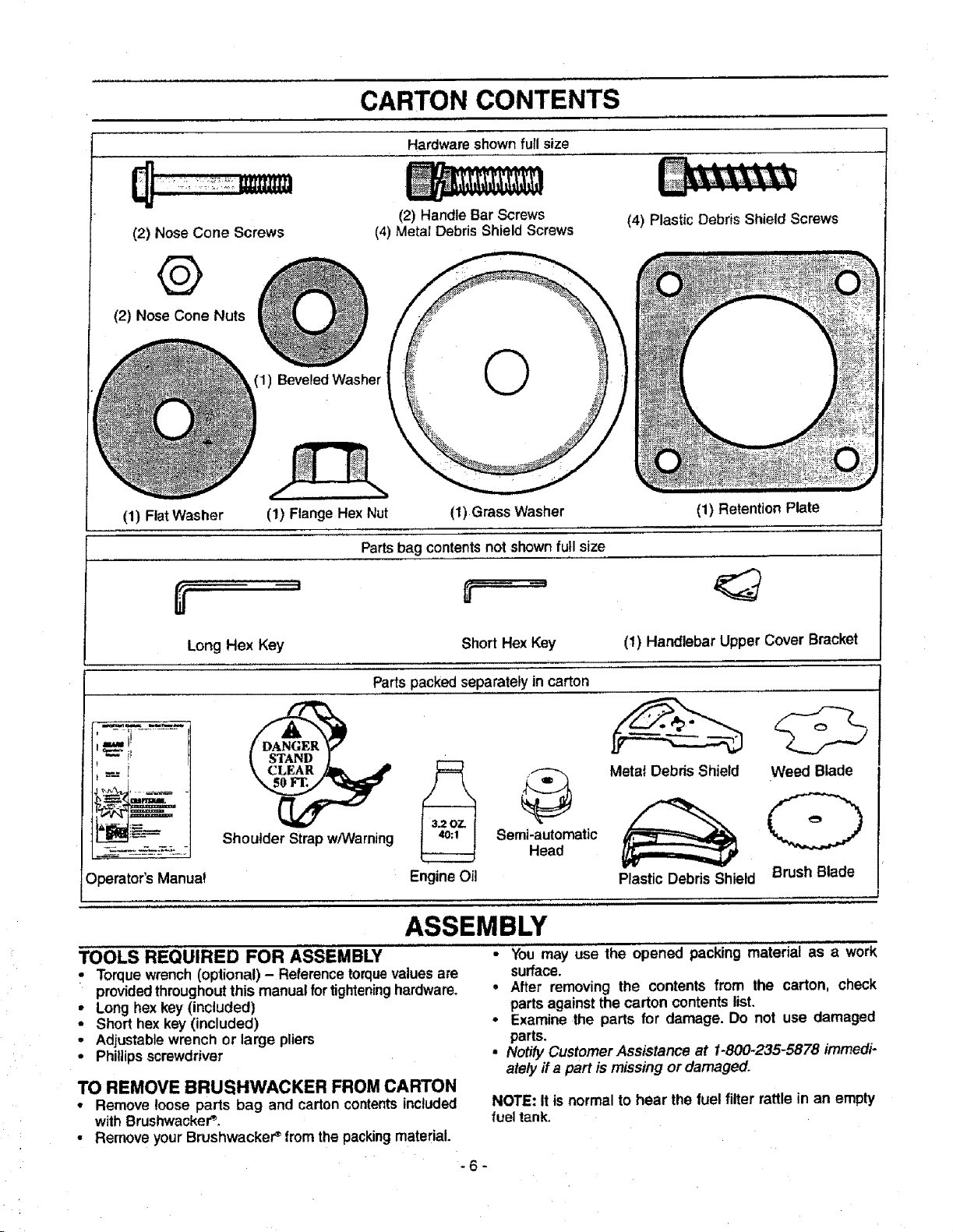
CARTON CONTENTS
Hardware shownfull size
(2) Nose Cone Screws
@
(2) Nose Cone Nuts
(2) Handle Bar Screws
(4) Metal Debris Shield Screws
(1) BeveledWasher
(4) Plastic Debris Shield Screws
(1) Flat Washer (1) Flange Hex Nut (1) Grass Washer (1) Retention Plate
Parts bag contents not shown full size
Long Hex Key Short HexKey
Partspacked separately in carton
(1) Handlebar Upper Cover Bracket
;-il...........
!
Shoulder Strap w/Warning
Operator'sManua_ EngineOil
ASSEMBLY
_ Semi-i_Uta_dmatic
Metat Debris Shield
Plastic Debris Shield
Weed Blade
(D
Brush Blade
TOOLS REQUIRED FOR ASSEMBLY
• Torquewrench(optional) - Referencetorquevaluesare
providedthroughoutthis manualfortighteninghardware,
• Long hexkey (included)
• Short hex key (included)
• Adjustablewrench or large pliers
• Phillipsscrewdriver
TO REMOVE BRUSHWACKER FROM CARTON
• Remove loose parts bag and carton contents included
with Brushwacker _
• Remove yourBrushwackeP from the packingmaterial.
• You may use the opened packing material as a work
surface
° After removing the contents from the carton, check
parts againstthe carton contentslist
• Examinethe parts for damage Do not use damaged
parts
• Notify Customer Assistance at 1-800-235-5878 immedi-
ately ffa part ismissing or damaged
NOTE: Itis normal to hear the fuel filter rattle in an empty
fueltank.
-6-
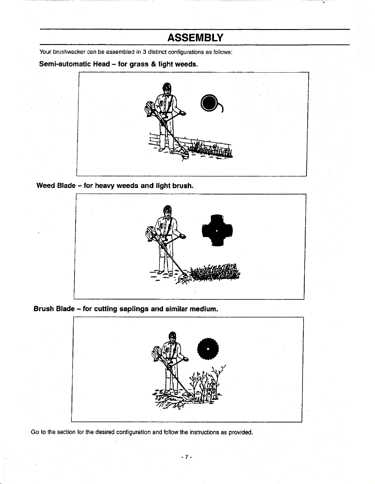
ASSEMBLY
Your brushwacker can be assembled in 3 distinct configurations as follows:
Semi-automatic Head - for grass & light weeds,
Weed Blade - for heavy weeds and light brush.
Brush Blade - for cutting saplings and similar medium.
Go to the section for the desired configuration and follow the instructionsas provided.
-7-
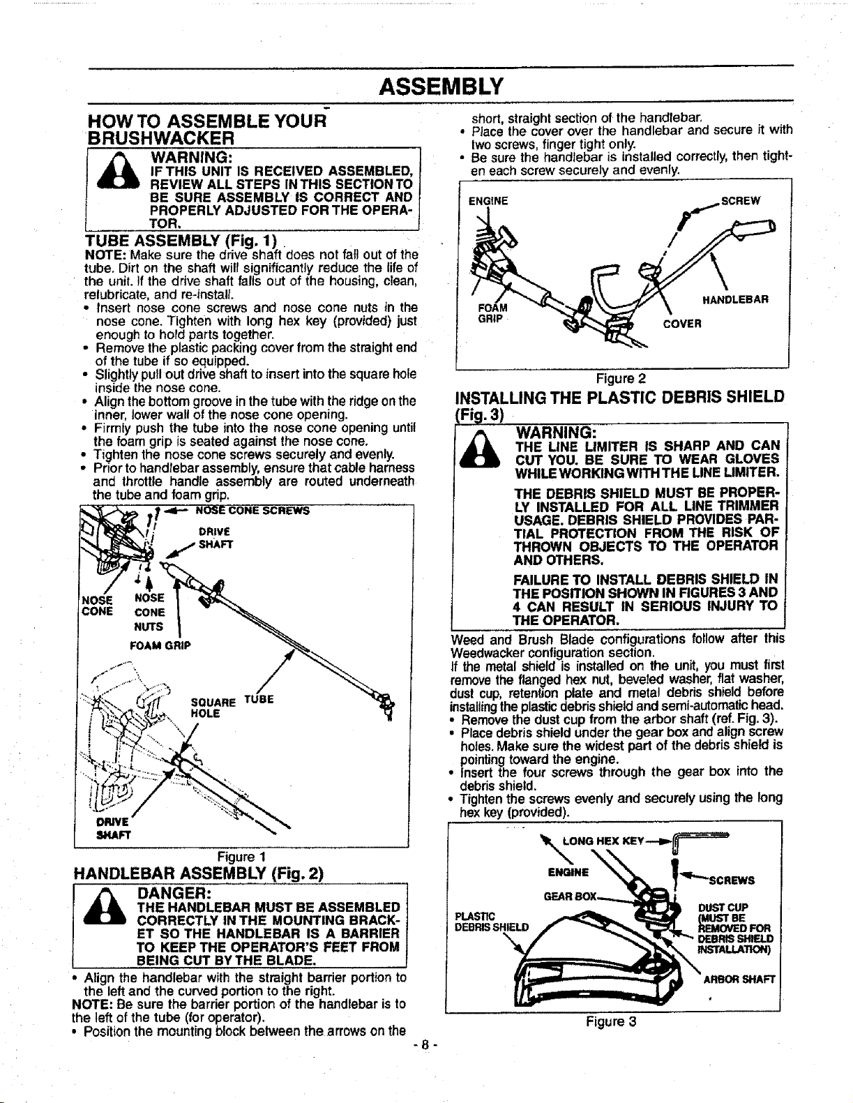
ASSEMBLY
HOW TO ASSEMBLE 'fOUR"
BRUSHWACKER
_ ARNING:
IF THIS UNIT IS RECEIVED ASSEMBLED,
REVIEW ALL STEPS IN THIS SECTION TO
BE SURE ASSEMBLY IS CORRECT AND
PROPERLY ADJUSTED FOR THE OPERA-
TOR,
TUBE ASSEMBLY (Fig. I)
NOTE: Make sure the drive shaft does not fall out of the
tube. Dirt on the shaft will significantly reduce the life of
the unit. !f the drive shaft fails out of the housing, clean,
relubricate, and re-instalL
• Insert nose cone screws and nose cone nuts in the
nose cone. Tighten with long hex key (provided) just
enough to hold parts together.
• Remove the plastic packing cover from the straightend
of the tube if so equipped.
• Slightly pull out drive shaft to insert into the square hole
inside the nose cone.
• Align the bottom groove in the tube withthe ridge on the
inner, lower wall of the nose cone opening.
• Firmly push the tube into the nose cone opening until
the foam grip isseated against the nose cone.
• Tighten the nose cone screws securely and evenly.
• Prior to handlebar assembly, ensure that cable harness
and throttle handle assembly are routed underneath
the tube and foam grip,
NOSE CONE SCREWS
NOSE NOSE
CONE CONE
NUTS
DRIVE
j SHAFT
FOAM GRIP
Figure 1
HANDLEBAR ASSEMBLY (Fig. 2)
i_ DANGER:
THE HANDLEBAR MUST BE ASSEMBLED
CORRECTLY IN THE MOUNTING BRACK-
ET SO THE HANDLEBAR IS A BARRIER
TO KEEP THE OPERATOR'S FEET FROM
BEING CUT BYTHE BLADE.
Align the handlebar with the straight barrier portion to
the left and the curved portion to the right.
NOTE: Be sure the barrier portion of the handlebar is to
the left of the tube (for operator).
, Position the mounting block between the arrowson the
-8-
short, straight section of the handlebar.
° Place the cover over the handlebar and secure it with
twoscrews, finger tight only.
• Besure the handlebar is installed correctly, then tight-
en each screw securely and evenly.
ENGINE
SCREW
FOAM HANDLEBAR
GRIP COVER
Figure 2
INSTALLING THE PLASTIC DEBRIS SHIELD
_ ARNING:
THE LINE LIMITER IS SHARP AND CAN
CUT YOU. BE SURE TO WEAR GLOVES
WHILE WORKING WITH THE LINELIMtTER.
THE DEBRIS SHIELD MUST BE PROPER-
LY INSTALLED FOR ALL LINE TRIMMER
USAGE. DEBRIS SHIELD PROVIDES PAR-
TIAL PROTECTION FROM THE RISK OF
THROWN OBJECTS TO THE OPERATOR
AND OTHERS.
FAILURE TO INSTALL DEBRIS SHIELD IN
THE POSITION SHOWN IN FIGURES 3 AND
4 CAN RESULT IN SERIOUS INJURY TO
THE OPERATOR.
Weed and Brush Blade configurations follow after this
Weedwacker configurationsection.
If the metal shield is installed on the unit, you must first
remove the flan_ed hex nut, beveled washer, flat washer,
dust cup, retenbon plate and metal debris shield before
installingthe plastic debris shield and semi-automatic head.
o
Remove the dust cup from the arbor shaft (ref. Fig. 3).
• Place debris shield under the gear box and align screw
holes. Make sure the widest part of the debris shield is
pointing toward the engine.
• Insert the four screws through the gear box into the
debris shield.
° Tighten the screws evenly and securely using the long
hex key (provided).
r-
ENGINE
DUST CUP
PLASTIC (MUST BE
DEBRISSHIELD REMOVED FOR
"_ DEBRIS SHIELD
INSTALLATION)
ARBOR SHAFT
Figure 3
ASSEMBLY
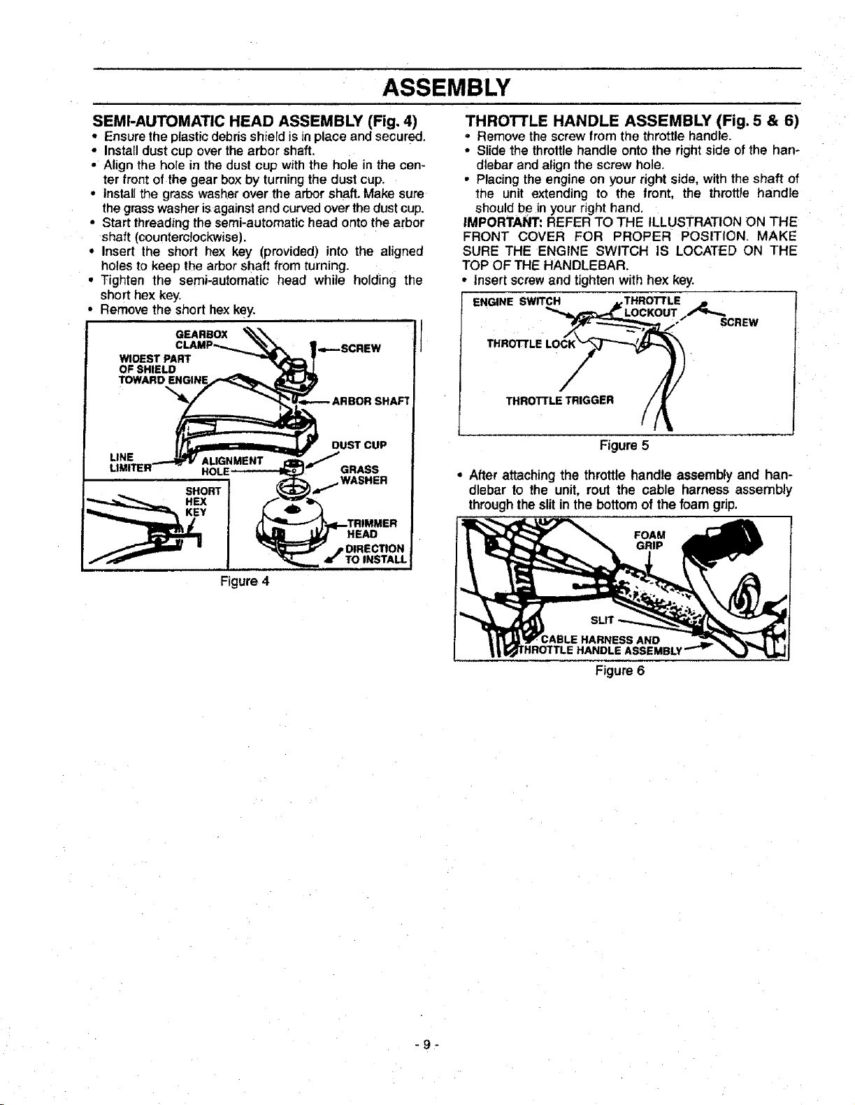
SEMI-AUTOMATIC HEAD ASSEMBLY (Fig. 4)
• Ensurethe plasticdebrisshield isin place and secured.
• Installdust cup overthe arbor shaft.
• Align the hole in the dust cup withthe hole in the cen-
ter front of the gear box by turning the dust cup.
• Installthe grass washer over the arbor shaft. Make sure
the grass washer isagainst and curved over the dust cup.
• Start threading thesemi-automatic head onto the arbor
shaft (counterclockwise).
• Insert the short hex key (provided) into the aligned
holes to keep the arbor shaft from turning.
• Tighten the semi-automatic head while holding the
short hex key.
• Remove the short hex key.
GEARBOX
WIDEST PART
OF SHIELD
THROTTLE HANDLE ASSEMBLY (Fig. 5 & 6)
• Remove the screwfrom the throttle handle.
• Slide the throttlehandle onto the rightside ofthe han-
dlebar and align the screw hole.
• Placing the engine on your right side, with the shaft of
the unit extending to the front, the throttle handle
should be in your right hand,
IMPORTANT: REFER TO THE ILLUSTRATION ON THE
FRONT COVER FOR PROPER POSITION. MAKE
SURE THE ENGINE SWITCH IS LOCATED ON THE
TOP OF THE HANDLEBAR.
• Insert screw and tighten with hex key.
ENGINE SWITCH THROT'rLE
SCREW
THROTTLE
THRO'FrLE TRIGGER
Figure 5
• After attaching the throttle handle assembly and han-
dlebar to the unit, rout the cable harness assembly
through the slit in the bottom of the foam grip.
FOAM
GRIP
ABLE HARNESS AND
HANDLE ASSEMBLY
Figure 6
-9-
ASSEMBLY
I I iii
BRUSHWACKER CONFIGURATION
Assembly information for Weedwacker configuration is
located before this section, the Brush Blade configura-
tion follows after thissection.
DANGER:
THE METAL SHIELD MUST BE PROPERLY
INSTALLED ON THE TOOL ANYTIME THE
TOOL IS USED WITH THE BLADE. THE
FORWARD TIP ON THE METAL SHIELD
HELPS TO REDUCE THE OCCURRENCEOF
BLADE THRUST WHICH CAN CAUSE
SERIOUS INJURY SUCHAS AMPUTATION
TOTHEOPERATORORBYSTANDERS.
FAILURETO INSTALLTHE DEBRIS SHIELD
IN THE POSITION SHOWNCAN RESULT IN
SERIOUSINJURYTO THE OPERATOR.THE
LENGTHOF THE DEBRISSHIELD MUST BE
ALIGNEDWRH THE LENGTHOF THE DRIVE
SHAFTHOUSING.
THE BLADEIS SHARPANDCAN CUT YOU.
BE SURE TO WEAR GLOVES WHILE
WORKING WITH BLADES
METAL DEBRIS SHIELD ASSEMBLY (Fig. 7)
NOTE: If your unitis equippedas a line trimmer,remove
the semi-automatic head, grass washer, and plastic
debris shield.Storepartsfor future use.
• Remove and discardthe packingcoverfrom the arbor
shaft, if so equipped_
• Remove the dustcup.Save for later use.
• Position the retention plate on the underside of the
metal debris shield and align screwholes. Make sure
the flat side of the plate is against the metal debris
shield.
• Hold the retentionplate in positionand place the metal
debrisshield underthegear box.Alignscrewholes.
• Insertthe four metaldebdsshield screwsone at a time
through the gear box and debris shield, then thread
them intothe retentionplate,
• Tighten the debris shield screwsevenly and securely
with the long hex key (provided),
HEX
_'q_ SCREW KEY
GEAR
_I_'_DUST CUP
i I _-*" ARBOR
METAL I SHAFT
SHIELD _
RETENTION
PLATE
ii ii i iiiiIIIH
WEED BLADE ASSEMBLY (Fig. 8)
• Installthe dust cup overthe arbor shaft.
• Install blade over arbor shaft, making sure the hole in
the center of the blade is fitted around the raised cen-
ter on the dust cup.
• Install the large flat washer, beveled washer and
flanged hex nut as shown. Be sure beveled washer is
installed as shown in Figure 8 (inset).
• Align hole in the dust cupwith the holein the side of the
gear box by turningthe dust cup.
• insert the short hex key (provided) into the aligned
holes.
• While holding the short hex key in position, firmly tight-
en flanged hex nutcounterclockwisewith a wrench.
• Remove the short hex key.
• Turnblade by hand. ft the blade binds against the metal
debris shield, blade is not centered. Reinstall blade.
NOTE: To remove the blade, align holes as in step
above;then, insert the short hex key.Unthread hex flange
nut and remove parts. Be sure to store the blade, flat
washer,cupped washer, and hex flange nutfor future use.
T CUP
%LARGE
_.. _ __ FLAT
BLADE _ _4_I"WASHER
_1- BEVELED
(_";) WASHER
NUT-- _ _
Ji _ i,J , . L,. LI
CUPPED SIDE
SHORT HEX KEY
TOWARD BEVELED
Figure 8
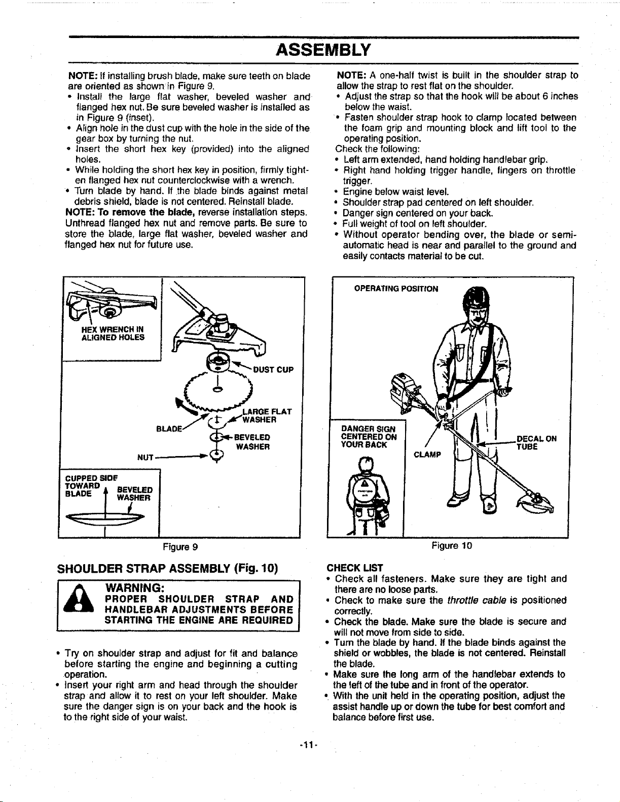
BRUSH BLADE ASSEMBLY (Fig. 9)
Assembly informationfor Weedwacker configuration is
locatedbeforethis section.
If plastic debris shield is installedon the unit, you must
first remove the semi-automatic head and plastic debris
shield before installing metal debris shield and blade. If
you have already configured your unit for weed blade
use, you have already installed the metal shield and
should remove the weed blade.
• Installthe dust cup overthe arbor shaft.
, Install blade over arbor shaft, making sure the hole in
the center of the blade is fitted around the raised
center on the dust cup.
Figure 7
-10-
ASSEMBLY
NOTE: If installing brush blade, make sure teeth on blade
are oriented as shownin Figure 9.
• Instal_ the large flat washer, beveled washer and
flanged hex nut. Be sure beveled washer is instaiJed as
in Figure 9 (inset).
• Aiign hole inthe dust cup with the hole in the side of the
gear box by turning the nut.
° Insert the short hex key (provided) into the aligned
holes,
• While holding the short hex key in position,firmIy tight-
en flanged hex nut counterclockwise with a wrench.
° Turn blade by hand. If the blade binds against metal
debris shield, blade is not centered. Reinstall blade.
NOTE: To remove the blade, reverse installation steps.
Unthread flanged hex nut and remove parts.Be sure to
store the blade, large flat washer, beveled washer and
flanged hex nut for future use,
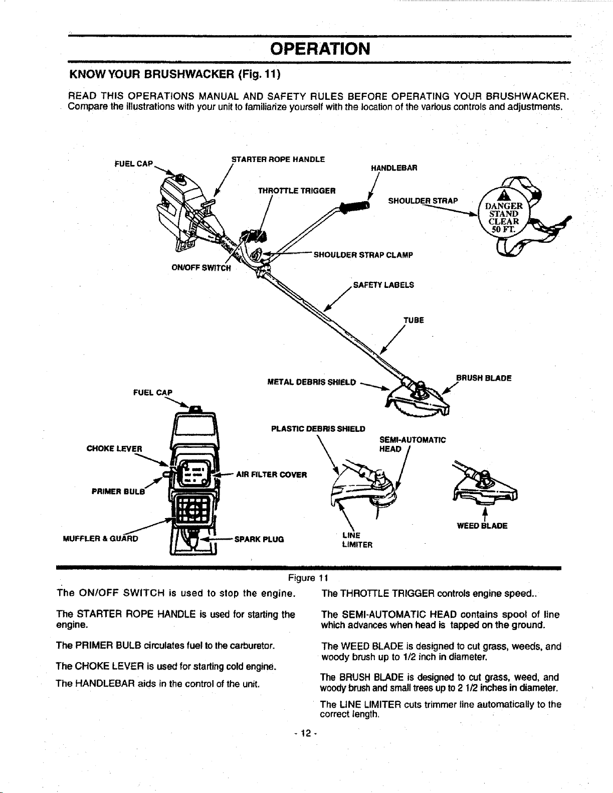
NOTE: A one-half twist is built in the shoulder strap to
allow the strap to rest flat on the shoulder.
° Adjust the strap so that the hook wilt be about 6 inches
below the waist.
• Fasten shoulder strap hook to clamp located between
the foam grip and mounting block and lift tool to the
operating position.
Check thefollowing:
• Left arm extended, hand holding handlebar grip.
• Right hand holding trigger handle, fingers on throttle
trigger.
• Engine below waist tevel.
• Shoulder strap pad centered on left shoulder.
• Danger sign centered on your back.
• Fullweight of tool on leftshoulder.
• Without operator bending over, the blade or semi-
automatic head is near and parallel to the ground and
easily contacts material to be cut.
HEX WRENCH IN
ALIGNED HOLES
VASHER
NUT _-
WASHER
CUPPED SIDE
TOWARD
==1An= _ BEVELED
ii i
Figure 9
SHOULDER STRAP ASSEMBLY (Fig. 10)
I_ WARNING: J
PROPER SHOULDER STRAP AND 1
HANDLEBAR ADJUSTMENTS BEFORE !
STARTING THE ENGINE ARE REQUIRED J
• Try on shoulder strap and adjust for fit and balance
before starting the engine and beginning a cutting
operation.
• Insert your right arm and head through the shoulder
strap and allow it to reston your left shoulder. Make
sure the danger sign is on your back and the hook is
to the rightsideof your waist.
OPERATING POSITroN
DANGER SIGN
CENTERED ON
YOUR BACK
CLAMP
DECALON
Figure 10
CHECK LIST
• Check all fasteners. Make sure they are tight and
there are no loosepads.
• Check to make sure the throttle cable is positioned
correctly.
° Check the blade. Make sure the blade is secure and
willnot movefromside to side.
° Turn the blade by hand. if the blade binds againstthe
shield or wobbles,the blade is not centered. Reinstall
the blade.
° Make sure the long arm of the handlebar extends to
the left of the tube and in front of the operator.
• With the unit held in the operating position, adjust the
assisthandle up or down the tube for best comfort and
balance before first use.
-11-
ii ii .||11 i i ii
OPERATION
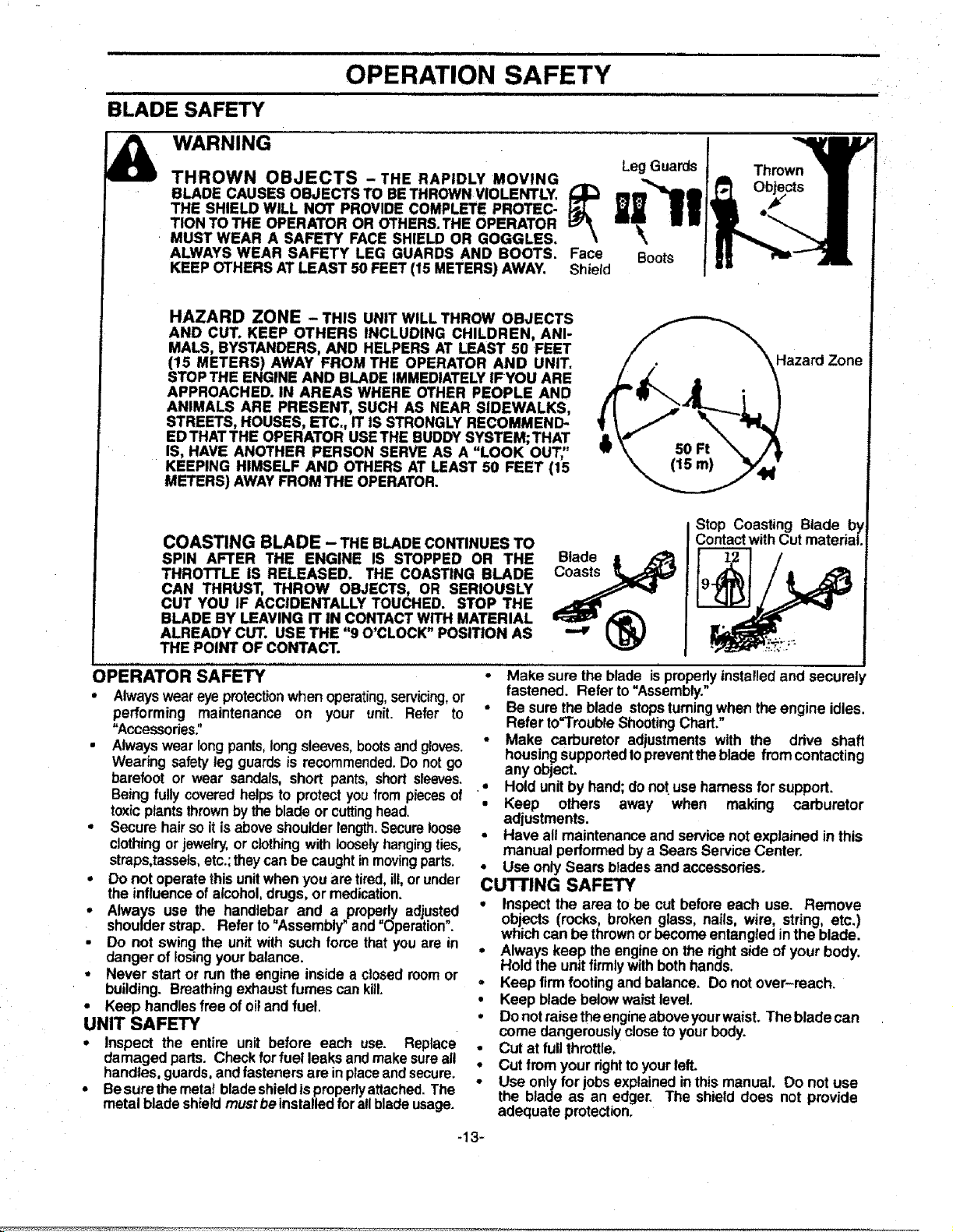
KNOW YOUR BRUSHWACKER (Fig. 11)
READ THIS OPERATIONS MANUAL AND SAFETY RULES BEFORE OPERATING YOUR BRUSHWACKER.
Compare the illustrationswith your unit tofamiliarize yourself with the location of the various controls and adjustments.
FUEL CAP
ON/OFF SWITCH
STARTER ROPE HANDLE
/
THROTrLE TRIGGER
/
HANDLEBAR
; SHOULO
SAFETY LABELS
TUBE
/
FUEL CAP
BRUSH BLADE
CHOKE LEVER
MUFFLER & GU_D
PLASTIC DEBRIS SHIELD
\ SEM!*AUTOMATIC
COVER _@_AD!
LINE
LIMITER
WEED BLADE
IIIIIIIIIIIII I IIII IIIIII IIIIIIII II IIIIIII II IIIIIIIIIIIIIIII II
Figure 1t
The ON/OFF SWITCH is used to slop the engine. The THRO'I-FLE TRIGGER controlsengine speed..
The STARTER ROPE HANDLE is used for startingthe
engine.
The SEMI-AUTOMATIC HEAD contains spool of line
which advanceswhen head is tappedon the ground.
The PRIMER BULB circulatesfuel tothecarburetor.
The CHOKE LEVER is used for startingcoldengine.
The HANDLEBAR aids in the controlof the unit.
The WEED BLADE is designed to cutgrass, weeds, and
woody brushup to !/2 inch indiameter.
The BRUSH BLADE is designedto cut grass, weed, and
woodybrushand smalltreesupto2 t/2 inchesin diameter.
The LINE LIMITER cutstrimmer fine automatically to the
correctlength.
-t2-
r mlJ,_L =======,, ,,, ,,,, == =
OPERATION SAFETY
BLADE SAFETY
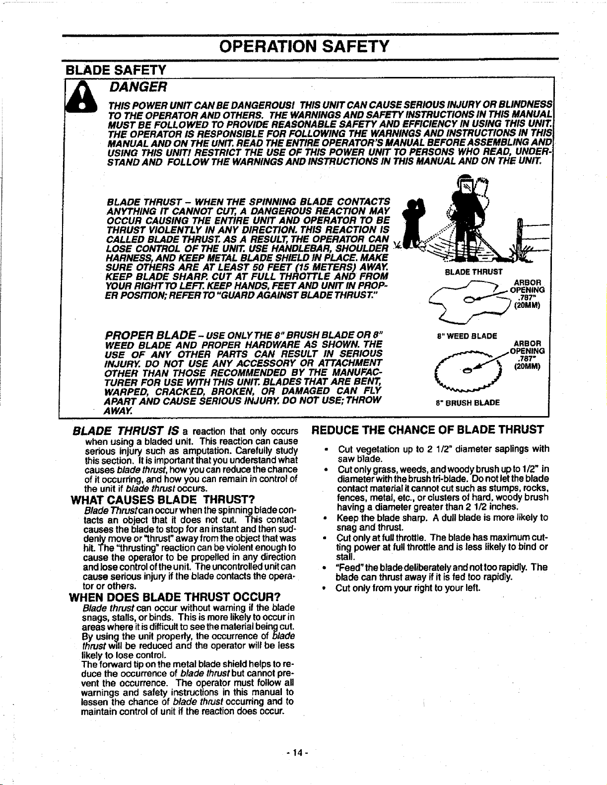
WARNING
THROWN OBJECTS -THE RAPIDLY MOVING
BLADE CAUSES OBJECTS TO BETHROWNVIOLENTLY. _;_
THE SHIELD WILL NOT PROVIDE COMPLETE PROTEC-
TION TO THE OPERATOR OR OTHERS.THE OPERATOR
MUST WEAR A SAFETY FACE SHIELD OR GOGGLES.
ALWAYS WEAR SAFETY LEG GUARDS AND BOOTS. Face
KEEP OTHERS AT LEAST 50 FEET (15 METERS) AWAY. Shield
LegGuards
Boots
HAZARD ZONE - THIS UNIT WILL THROW OBJECTS
AND CUT. KEEP OTHERS INCLUDING CHILDREN, ANI-
MALS, BYSTANDERS, AND HELPERS AT LEAST 50 FEET
(15 METERS) AWAY FROM THE OPERATOR AND UNIT.
STOPTHE ENGINE AND BLADE IMMEDIATELYIFYOU ARE
APPROACHED. IN AREAS WHERE OTHER PEOPLE AND
ANIMALS ARE PRESENT, SUCH AS NEAR SIDEWALKS,
STREETS, HOUSES, ETC., IT IS STRONGLY RECOMMEND-
EDTHATTHE OPERATOR USETHE BUDDY SYSTEM;THAT
IS, HAVE ANOTHER PERSON SERVE AS A "LOOK OUT,"
KEEPING HIMSELF AND OTHERS AT LEAST 50 FEET (15
METERS) AWAYFROM THE OPERATOR.
Hazard Zone
COASTING BLADE - THE BLADE CONTINUES TO
SPIN AFTER THE ENGINE IS STOPPED OR THE
THROTTLE IS RELEASED. THE COASTING BLADE
CAN THRUST, THROW OBJECTS, OR SERIOUSLY
CUT YOU IF ACCIDENTALLY TOUCHED. STOP THE
BLADE BY LEAVING IT IN CONTACT WITH MATERIAL
ALREADY CUT. USE THE "9 O'CLOCK" POSITION AS
THE POINT OF CONTACT.
Blade
Coasts
Stop Coasting Blade by
Contact withCut material.
OPERATOR SAFETY
• Alwaysweareyeprotectionwhen operating,servicing,or
performing maintenance on your unit. Refer to
"Accessories:'
• Alwayswear longpants,long sleeves,bootsand gloves.
Wearing safetyleg guards is recommended.Do notgo
barefoot or wear sandals, short pants,short sleeves.
Being fully coveredhelpsto protectyoufrom piecesof
toxicplantsthrownbythebladeor cuttinghead.
• Secure hairsoit isaboveshoulderlength.Secureloose
clothingorjewelry,or clothingwith loosely hangingties,
straps,tassels,etc.;theycanbe caughtinmovingparts.
• Do not operatethisunitwhen youare tired,ill,orunder
the influenceof alcohol,drugs, or medication.
° Always use the handlebar and a properly adjusted
shoulderstrap. Refer to"Assembly" and "Operation".
• Do not swing the unitwith such force thatyou are in
danger of losing yourbalance.
• Never startor run the engine inside a closedroomor
building. Breathingexhaustfumes can kill.
• Keep handles free ofoiland fuel,
UNIT SAFETY
° Inspect the entire unit before each use. Replace
damaged parts. Check forfuel leaksand makesureall
handles, guards,andfasteners are inplaceand secure.
• Besure themetat bladeshieldisproperlyattached.The
metal bladeshieldmustbe installedfor allbladeusage.
• Make sure the blade isproperlyinstalledand securely
fastened. Refer to "Assembly."
, Be sure the blade stopsturningwhen the engine idles.
Refer to'Trouble ShootingChart."
* Make carburetor adjustments with the drive shaft
housingsupportedtopreventtheblade from contacting
any object.
• Hold unitby hand;do not use harness for support.
• Keep others away when making carburetor
adjustments.
• Have all maintenanceand servicenot explained in this
manual performedbya SearsService Center.
• Use onlySears bladesand accessories.
CUI"I'ING SAFETY
• Inspect the area to be cut before each use. Remove
objects (rocks, broken glass, nails, wire, string, etc.)
whichcan be thrownorbecome entangledinthe blade.
. Always keep the engineon the rightside of your body,
Hold the unitfirmlywilhbothhands,
. Keep firm footing and balance. Do notover-reach.
• Keep blade belowwaistlevel.
• Do not raise theengineaboveyour waist. The blade can
come dangerouslyclose toyourbody.
• Cut at full throttle,
. Cut from your righttoyourleft.
• Use only for jobsexplainedinthis manual. Do not use
the blade as an edger. The shield does not provide
adequate protection.
-13-
i ,,i ,,,,i i,lul,ii
OPERATION SAFETY
BLADE .................................
SAFETY
DANGER
THIS POWER UNIT CAN BE DANGEROUS! THISUNIT CAN CAUSE SERIOUS INJURY OR BLINDNESS
TO THE OPERATOR AND OTHERS. THE WARNINGS AND SAFETY INSTRUCTIONS IN THIS MANUAL
MUST BE FOLLOWED TO PROVIDE REASONABLE SAFETY AND EFFICIENCY IN USING THIS UNIT.
THE OPERATOR IS RESPONSIBLE FOR FOLLOWING THE WARNINGS AND INSTRUCTIONS IN THIS
MANUAL AND ON THE UNIT,,READ THE ENTIRE OPERATOR S MANUAL BEFORE ASSEMBLING AND
USING THIS UNIT! RESTRICT THE USE OF THIS POWER UNIT TO PERSONS WHO READ, UNDER-
STAND AND FOLLOW THE WARNINGS AND INSTRUCTIONS IN THIS MANUAL AND ON THE UNIT.
BLADE THRUST- WHEN THE SPINNING BLADE CONTACTS
ANYTHING IT CANNOT CUT, A DANGEROUS REACTION MAY
OCCUR CAUSING THE ENTIRE UNIT AND OPERATOR TO BE
THRUST VIOLENTLY IN ANY DIRECTION. THIS REACTION IS
CALLED BLADE THRUST. AS A RESULT, THE OPERATOR CAN
LOSE CONTROL OF THE UNIT. USE HANDLEBAR, SHOULDER
HARNESS, AND KEEP METAL BLADE SHIELD IN PLACE, MAKE
SURE OTHERS ARE AT LEAST 50 FEET (15 METERS) AWAY.
KEEP BLADE SHARP. CUT AT FULL THROTTLE AND FROM
YOUR RIGHT TOLEFt. KEEP HANDS, FEET AND UNIT IN PROP-
ER POSITION; REFER TO"GUARD AGAINST BLADE THRUST,"
PROPER BLADE- USE ONLY THE 8°'BRUSH BLADE OR 8"
WEED BLADE AND PROPER HARDWARE AS SHOWN. THE
USE OF ANY OTHER PARTS CAN RESULT IN SERIOUS
INJURY. DO NOT USE ANY ACCESSORY OR ATTACHMENT
OTHER THAN THOSE RECOMMENDED BY THE MANUFAC-
TURER FOR USE WITH THIS UNIT. BLADES THAT ARE BENT,
WARPED, CRACKED, BROKEN, OR DAMAGED CAN FLY
APART AND CAUSE SERIOUS INJURY, DO NOT USE; THROW
AWAY,
8" WEED BLADE
ARBOR
(20MM)
8" BRUSH BLADE
BLADE THRUST IS a reaction that only occurs
when using a bladed unit. This reactioncan cause
serious injurysuch as amputation. Carefullystudy
thissection. Itis importantthatyouunderstandwhat
causesblade thrust,howyoucanreducethechance
ofitoccurring,and how you canremainin controlof
the unitifblade thrustoccurs.
WHAT CAUSES BLADE THRUST?
Blade Thrustcanoccurwhen thespinningbladecon-
tacts an object that it does not cut. This contact
causesthe bladeto stopforan instantand thensud-
denlymove or "thrust"away fromthe objectthatwas
hit.The "thrusting" reactioncanbeviolentenoughto
cause the operatorto be propelledin any direction
and Josecontrolotthe unit. Theuncontrolledunitcan
cause sedous injuryifthe bladecontactstheopera-
toror others.
WHEN DOES BLADE THRUST OCCUR?
Blade thrustcan occurwithoutwarningif the blade
snags,stalls,or binds. This ismore likelytooccurin
areaswhere itisdifficulttoseethematedal beingcut.
By using the unitproperly,the occurrenceof blade
thrustwill be reducedand the operatorwillbe less
likelyto lose control.
The forward tiponthe metal bladeshieldhelpsto re-
duce the occurrenceofblade thrustbutcannotpre-
vent the occurrence. The operatormust followall
warnings and safety instructionsin this manual to
lessen the chance of blade thrustoccurringand to
maintain controlofunitif the reactiondoes occur.
REDUCE THE CHANCE OF BLADE THRUST
• Cut vegetation up to 2 1/2" diameter saplingswith
saw blade.
• Cutonlygrass,weeds,andwoodybrushupto1/2" in
diameterwiththebrushtri-blade. Donotletthe blade
contactmaterialitcannotcutsuchas stumps,rocks,
fences, metal, etc., orclustersofhard, woodybrush
having a diametergreaterthan 2 1/2 inches.
• Keep the blade sharp. Adullblade is more likelyto
snag and thrust.
• Cut onlyat fullthrottle.The bladehasmaximumcut-
tingpower at fullthrottleand is lesslikelyto bind or
stall.
• "Feed" thebladedeliberatelyandnottoo rapidly.The
bladecan thrustaway if itisfed too rapidly.
• Cut onlyfrom yourrighttoyourleft.
-14-
ii irl ii
ii : i iiiiiiiiiiii iiiii iii i i ii i =
OPERATION
i i|1 iii iii imll ii ii
WARNING:
THE BLADE CONTINUES TO SPIN
AFTER THE ENGINE IS TURNED OFF.
THE COASTING BLADE CAN SERIOUS-
LY CUT YOU IF ACCIDENTALLY
TOUCHED.
®
,.,,4"
THE OPERATOR OR OTHERS MUST
NOTTRY TO CLEAR AWAY CUT MATE-
RIAL WITH THE ENGINE RUNNING OR
THE BLADETURNING.
STOP ENGINE AND BLADE BEFORE
REMOVING MATERIALS WRAPPED
AROUND THE BLADE SHAFT.
!
j Stop Coasting Blade By
Contact With Cut Matarlal
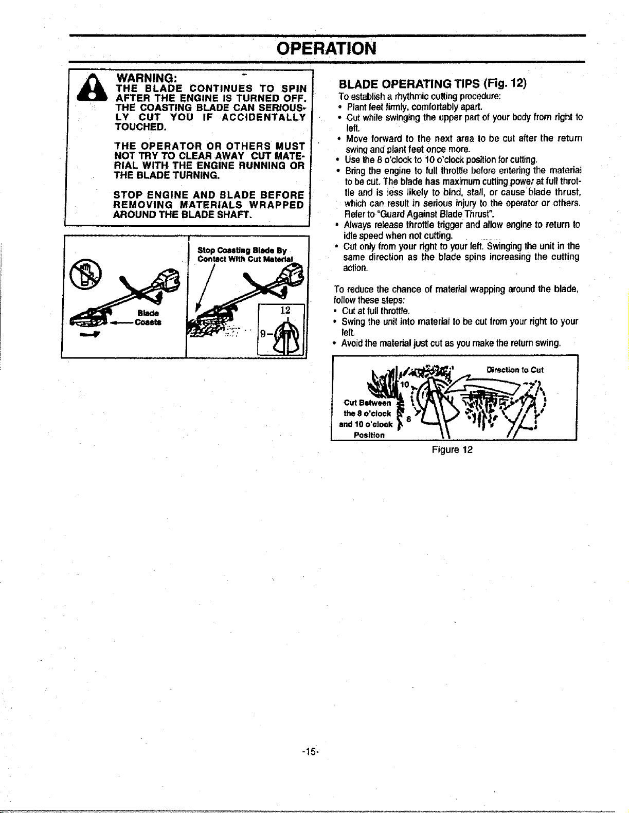
BLADE OPERATING TIPS (Fig. 12)
To establisha rhythmiccuttingprocedure:
,, Plantfeetfirmly,comfortablyapart.
• Cutwhileswingingtheupperpartofyourbodyfromrightto
left.
• Move forward to the nextarea to be cut afterthe return
swin.qendplantfeetoncemore.
• Usethe8 o'clockto 10o'clockpositionforcutting.
• Bring theengineto fullthrottlebeforeenteringthe maleriat
tobecut.Thebladehasmaximumcuttingpoweratfull throt-
tie and is lesslikely to bind, stall,or causeblade thrust,
whichcanresultin seriousinjurytotheoperatoror others.
Referto"GuardAgainstBladeThrust".
• Alwaysreleasethrottletdggerandallowengineto returnto
idlespeedwhennot cutting............
• Cutonlyfromyourrighttoyourloll, Swingingtheunitinthe
same directionas the blade spinsincreasingthe cutting
action.
To reducethechanceof mateda!wrappingaroundtheblade,
followthesesteps:
• Cutat furlthrottle.
• Swingthe unitinto materialtobecutfromyourrighttoyour
left.
• Avoidthematerialjustcutasyoumakethereturnswing.
Direction to Cut
Cut Between t
the 8 o'clock
and 10 o'clock =
Position
Figure12
-15-
i iii i Ji i
OPERATION SAFETY
ii ilUUl
i i i
LINE TRIMMER SAFETY
LEG GUARDS
_ WARNING:
THE RAPIDLY MOVING LINE CAUSES OBJECTS TO BE
THROWN VIOLENTLY. THE PLASTIC DEBRIS SHIELD
WILL NOT PROVIDE COMPLETE PROTECTION TO THE
OPERATOR OR OTHERS. THE OPERATOR MUST
WEAR A SAFETY FACE SHIELD OR GOGGLES.
ALWAYS WEAR HEAVY, LONG PANTS AND BOOTS.
KEEP OTHERS AT LEAST 50 FEET (15 METERS) AWAY.
THIS UNIT WILL THROW OBJECTS AND CUT. KEEP
OTHERS INCLUDING CHILDREN, ANIMALS,
BYSTANDERS AND HELPERS AT LEAST 50 FEET (15
METERS) AWAY FROM THE OPERATOR AND UNIT.
STOP THE ENGINE IF YOU ARE APPROACHED.
TRIMMER HEAD PARTS THAT ARE CHIPPED,
CRACKED OR DAMAGED IN ANY OTHER WAY CAN
FLY APART AND CAUSE SERIOUS INJURY. DO NOT
USE. REPLACE DAMAGED PARTS BEFORE USING THE
UNIT.
\ BOOTS
EYE PROTECTION
_._i _ ._ Hazard Zone
SEMI-AUTOMATIC HEAD
USE ONLY GOOD QUALITY
REPLACEMENT PARTS
OPERATOR SAFETY
• Always weareye protectionwhen operating,servicing,
or performingmaintenance on yourunit. Refer to =Ac-
cessones."
• Do notoperate thistoolwhen youare tired,illor under
the influenceof alcohol, drugs, or medication.
• Alwayswearlong pants,long sleeves,bootsand gloves.
Wearing safety leg guards is recommended.Do not go
barefoot or wear sandals, short pants, short sleeves.
Being fully covered helps to protectyou from pieces of
toxicplantsthrownbythe blade or cuttinghead.
• Secure hairsoit isabove shoulderlength.Secure loose
clothingorjewelry,or clothing with looselyhangingties,
straps,tassels,etc.;they can be caughtin movingpads.
• Do notswingthetoolwith suchforcethatyouare indan-
ger of losingyourbalance.
• Never startor run the engine inside a closed room or
building. Breathingexhaust fumes cankill.
• Keep handlesfree of oil and fuel
CUI-I'ING SAFETY
Inspect the area to be cut before each use. Remove
objects (rocks, broken glass, nails, wire, string, etc.)
whichcan be thrown or become entangled in the semi-
automatichead.
• Always use the shoulderstrap.
• Always keep the engine on theright sideof yourbody.
• Hold the unitfirmly with both hands.
• Keep firm footing and balance.Do not over-reach.
. Keep the semi-automaticheadbelow waistlevel.
• Do not raise the engine aboveyourwaist.
• Keep all parts of your bodyaway from the semi-auto-
matic head and mufflerwhen engine isrunning.
• Use onlyfor jobs explainedinthis manual.
• Cut from your right to your left.
UNIT SAFETY
• Inspectthe entire unitbefore each use. Replace dam-
aged parts. Check for fuel leaks and make sure all
handtes, guards, and fasteners are in place and
securelyfastened.
• Use only ..080_ diameter good quality monofilament
line. Never usewire or rope, string,etc.
• Be sure the plastic debrisshield isproperly attached.
• Make carburetor adjustments with the drive shaft
housing supported to prevent the line from contacting
anyobject.
,, Keep others away when making carburetor adjust-
ments.
• Useonly goodquality SEARS accessoriesor attachments.
-16.
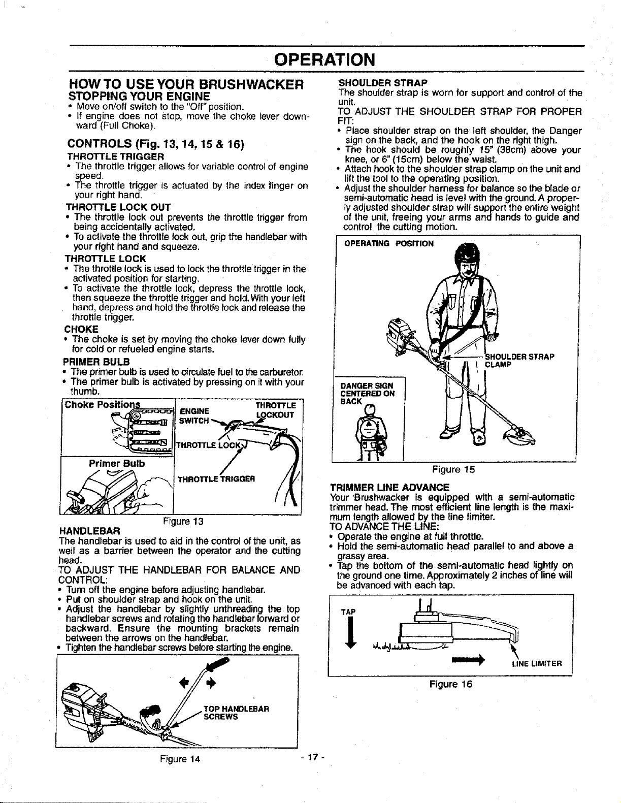
OPERATION
HOW TO USE YOUR BRUSHWACKER
STOPPING YOUR ENGINE
° Move on/off switchto the "Off" position.
• If engine does not stop, move the choke lever down-
ward (Ful! Choke).
CONTROLS (Fig. 13, 14, 15 & 16)
THROTTLE TRIGGER
• The throttle trigger allows for variable controi of engine
speed.
• The throttle tdgger is actuated by the index finger on
your right hand.
THROTTLE LOCK OUT
• The throttle lock out prevents the throttle trigger from
being accidentally activated.
• To activate the throttle toGkout, grip the handlebar with
your right hand and squeeze.
THROTTLE LOCK
• The throttle lock is used to lock the throttle trigger in the
activated position for starting.
• To activate the throttle lock, depress the throttle lock,
then squeeze the throttle trigger and hold.With your left
hand, depress and hold the throttle lock and release the
throttle trigger.
CHOKE
• The choke is set by moving the choke lever down fully
for cold or refueled engine starts.
PRIMER BULB
• The primer bulb is used to circulatefuel tothecarburetor.
• The primer bulb is activated by pressing on itwith your
thumb.
Choke Positions_ THROTTLE
Primer Bulb /
THROTTLE T/FIIGGER
Fi ure 13
HANDLEBAR
The handlebar is used to aid in thecontrolofthe unit, as
well as a barrier between the operator and the cutting
head.
TO ADJUST THE HANDLEBAR FOR BALANCE AND
CONTROL:
• Turn offthe engine beforeadjustinghandlebar.
• Put on shoulder strap and hookon the unit.
• Adjust the handlebar by slightlyunthreadingthe top
handlebar screwsand rotatingthehandlebarforwardor
backward. Ensure the mounting brackets remain
between the arrows on the handlebar.
Tighten the handlebar screws beforestarting theengine.
,TOP HANDLEBAR
SCREWS
SHOULDER STRAP
The shoulder strap is worn for support and control of the
unit.
TO ADJUST THE SHOULDER STRAP FOR PROPER
FIT:
• Place shoulder strap on the left shoulder, the Danger
sign on the back, and the hook on the right thigh.
• The hook should be roughly 15" (38cm) above your
knee, or 6" (15cm) below the waist.
• Attach hook to the shoulder strap clampon the unit and
lift the tool to the operating position.
, Adjust the shoulder harness for balance so the blade or
semi-automatic head is level with the ground.A proper-
ly adjusted shoulder strap will support the entire weight
of the unit, freeing your arms and hands to guide and
control the cutting motion.
OPERATING POSITION
CLAMP
DANGER SIGN
CENTERED ON
Figure 15
TRIMMER LINE ADVANCE
Your_Brushwacker is equipped with a semi-automatic
trimmer head.The most efficient line length is the maxi-
mum lengthallowed bythe tine fimiter.
TO ADVANCETHE LINE:
• Operate the engine at full throttle.
° Hold the semi-automatic head parallel to and above a
grassyarea.
° Tap the bottom of the semi-automatic head lightlyon
the groundone time, Approximately2 inchesof line will
be advancedwith each tap.
| I
• It _ __.j.t.; _JJ
LINE LtMITER
Figure 16
Figure 14 - 17 -
ii i IHIIIIIII'IIII I IIIIII I I I
OPERATION
ii ii iii inll i i ii
BEFORE STARTING ENGINE:
WARNING:
BE SURE TO READ THE FUEL SAFETY
INFORMATION IN THE SAFETY RULES
SECTION ONPAGE 2 OF THIS MANUAL
BEFORE YOU BEGIN.
IF YOU DO NOT UNDERSTAND THE FUEL
SAFETY SECTION DO NOT ATTEMPT TO
FUEL YOUR UNIT; SEEK HELP FROM
SOMEONE WHO DOES UNDERSTAND
THE FUEL SAFETY SECTION OR CALL
THE CUSTOMER ASSISTANCE-HOTLINE
AT 1-800-235-5878.
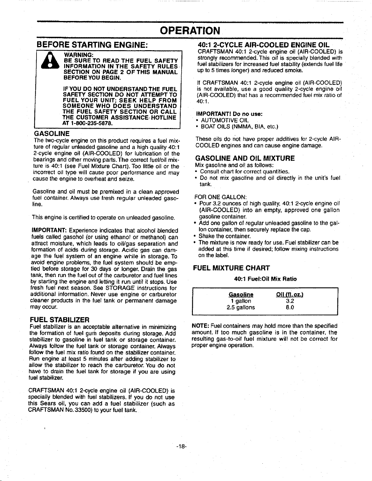
GASOLINE
The two-cycleengine on thisproduct requires a fuel mix-
ture of regular unleadedgasolineand a high quality40:1
2-cycle engine oil (AIR-COOLED) for lubrication of the
bearings and othermovingparts.The correctfuel/oil mix-
ture is 40:1 (see Fuel Mixture Chart). Too little oil or the
incorrectoil type will cause poor performance and may
cause the engine tooverheatand seize.
Gasoline and oil must be premixed in a clean approved
fuel container. Always use fresh regular unleaded gaso-
line.
This engine iscertifiedtooperate on unleaded gasoline.
IMPORTANT: Experience indicates that alcohol blended
fuels called gasohol (or usingethanol or methanol) can
attract moisture, which leads to oil/gas separation and
formation of acids during storage. Acidic gas can dam-
age the fuel system of an engine while in storage, To
avoid engine problems,the fuel system should be emp-
tied before storage for 30 days or longer. Drain the gas
tank, then run the fuel outof the carburetor and fuel lines
by startingthe engine and letting it run untilit stops.Use
fresh fuel next season. See STORAGE instructions for
additional information.Never use engine or carburetor
cTeanerproductsin the fuel tank or permanent damage
may occur,
FUEL STABILIZER
Fuel stabilizer is an acceptable alternative in minimizing
the formation of fuel gum deposits during storage. Add
stabilizer to gasoline in fuel tank or storage container.
Always followthe fuel tank or storage container.Always
followthe fuel mix ratiofoundon the stabilizer container.
Run engine at least 5 minutesafter adding stabilizer to
ailow the stabilizer to reach the carburetor. You do not
have to drain the fuet tank for storage if you are using
fuelstabilizer.
40:1 2-CYCLE AIR-COOLED ENGINE OIL
CRAFTSMAN 40:1 2-cycle engine oii (AIR-COOLED) is
strongly recommended.This oil is specially blended with
fuel stabilizersfor increased fuel stability(extendsfuel life
up to5 timeslonger) and reduced smoke.
If CRAFTSMAN 40:1 2-cycle engine oil (AIR-COOLED)
is not available, use a good quality 2-cycle engine oil
(AIR-COOLED) that has a recommended fuel mix ratio of
40:t,
IMPORTANT! Do no use:
• AUTOMOTIVE OIL
• BOAT OILS (NMMA, BIA, etc.)
These oilsdo not have proper additives for 2-cycle AIR-
COOLED engines and can cause engine damage.
GASOLINE AND OIL MIXTURE
Mixgasolineand oi!as follows:
° Consuifchart for correctquantities.
• Do not mix gasoline and oil directly in the unit's fuel
tank.
FOR ONE GALLON:
• Pour3.2 ounces of high quality, 40:1 2-cycle engine oit
(AIR-COOLED) into an empty, approved one gallon
gasoline container.
• Add one gallon of regular unleaded gasoline to the gal-
lon container, then securely replace thecap.
• Shake thecontainer.
• The mixture is now ready for use. Fuel stabilizer can be
added at this time if desired; follow mixing instructions
onthe label.
FUEL MIXTURE CHART
40:1 Fuel:Oil Mix Ratio
Oil {fl.oz.)
1 gallon 3.2
2.5 gallons 8.0
f
NOTE: Fuel containers may hold more than the specified
amount. If too much gasoline is in the container, the
resulting gas-to-oil fuel mixture witl not be correct for
properengineoperation.
CRAFTSMAN 40:1 2-cycle engine oil (AIR-COOLED) is
specially blended with fuel stabilizers. If you do not use
this Sears oil, you can add a fuel stabilizer (such as
CRAFTSMAN No.33500) toyourfuel tank.
-18-
,i,ii i ii ,11111 i i
STOPPING YOUR ENGINE:
* Movethe ON/OFF switchto the OFF position.
* Ifthe enginedoes notstop,movethe chokefever down-
ward (FullChoke).
i_ DANGER:
THE BLADE OR SEMI-AUTOMATIC HEAD
WILL TURN WHEN THE ENGINE STARTS,
FOR SAFE STARTING AND OPERATION,
FOLLOW ALL SAFETY PRECAUTIONS IN
THIS OPERATOR'S MANUAL AND
LABELS ONTHE UNIT. DRESS PROPERLY
BEFORE STARTING ENGINE.
AVOID ANY CONTACT WITH THE MUF-
FLER. A HOT MUFFLER CAN CAUSE
SERIOUS BURNS.
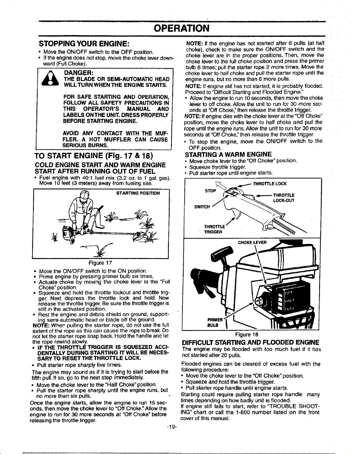
TO START ENGINE (Fig. 17 & 18)
COLD ENGINE START AND WARM ENGINE
START AFTER RUNNING OUT OF FUEL
- Fuel engine with 40:1 fuel mix (3.2 oz. to 1 gal. gas).
Move 10 feet (3 meters)away from fueling site.
STARTING POSITION
Figure 17
• Move the ON/OFF switch to the ON position.
• Prime engine by pressing primer bulb six times.
• Actuate choke by moving the choke lever to the "Full
Choke" position.
• Squeeze and hold the throttle lockout and throttle trig-
ger. Next depress the throttle lock and hold. Now
release the throttle trigger. Be sure the throttletrigger is
still in the activated position.
,, Rest the engine and debris shield on ground, support-
ing semi-automatic head or blade off the ground.
NOTE: Whe_ pulling the starter rope, do not use the full
extent of the rope as this can cause the rope to break. Do
not let the starter rope snap back. Hold the handle and let
the rope rewind slowty.
• IF THE THROTTLE TRIGGER IS SQUEEZED ACCI-
DENTALLY DURING STARTING IT WILL BE NECES-
SARY TO RESETTHE THROTTLE LOCK.
,, Pull starter rope sharplyfive limes,
The engine may soundas if itis trying to startbefore the
fifth pull.Ifso, go to the next step immediately.
• Move the choke leverto the "Half Choke"position.
• Pull the starter rope sharply until the engineruns,but
no more than six pulls.
Once the engine starts, allow the engine 1orun 15 sec-
onds,then movethe choke leverto "Off Choke."Allowthe
engine to runfor 30 more seconds at "Off Choke"before
releasing thethrottletrigger.
-19-
||11| i ......
OPERATION
NOTE: If the engine has not started after 6 pulls (at haft
choke), check to make sure the ON/OFF switch and the
choke lever are in the proper positions.Then, move the
choke lever to the full chokepositionand press the primer
bulb 6 times;pullthe starter rope2 more times. Move the
choke leverto half chokeand pullthe starter rope untilthe
engine runs,but no more than6 more pulls,
NOTE: If enginestillhas notstarted,il isprobablyflooded.
Proceed to"Difficult Starting andFloodedEngine:'
, Allowthe engineto run10seconds, then move thechoke
lever tooff choke.Allow the unit to run for 30 more sec-
ondsat "Off Choke;'then releasethe throttletrigger.
NOTE: Ifenginedieswiththechoke leverat the"Off Choke"
position,move the choke leverto half choke and pu]fthe
ropeuntillhe engineruns. Allow the unittorunfor 30 more
secondsat "Off Choke,"then retease the throttletrigger.
• To stop the engine, move the ON/OFF switch to the
OFF position.
STARTING A WARM ENGINE
• Movechoke leverto the"Off Choke" position.
• Squeeze throttletrigger.
• Pullstarterropeuntilengine starts.
THROTrLE LOCK
STOP
THROTTLE
LOCK-OUT
SWITCH
THROTTLE
TRIGGER
CHOKELEVER
PRIMER
BULB
Figure 18
DIFRCULT STARTING AND FLOODED ENGINE
The engine may be flooded with too much fuel if it has
notstarted after20 pulls.
Flooded engines can be cleared of excess fuel with the
following procedure:
• Move thechokelever tothe "Off Choke*'position.
• Squeeze and holdthe throttle trigger.
• Pullstarter ropehandle untilengine slarts.
Starting could require pullingstarter rope handle many
timesdependingon how badly unitis flooded.
If engine still fails to start, refer to "TROUBLE SHOOT-
ING" chart or call the 1-800 number listed on the front
coverofthis manual.
i i i i iii i lillllll illll.==.ll iiii i i|
OPERATION
i i m m = NH II I= II ,I ,,,,
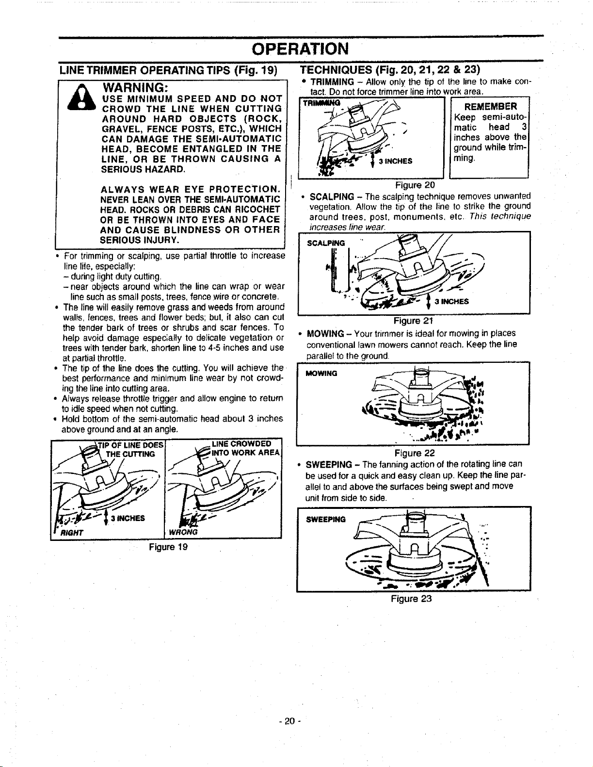
LINE TRIMMER OPERATING TIPS (Fig. 19) TECHNIQUES (Fig. 20, 21, 22 & 23)
• TRIMMING - Allow onlythe tip ofIhe line to make con-
tact. Do not force trimmerline into work area.
WARNING:
USE MINIMUM SPEED AND DO NOT
CROWD THE LINE WHEN CUTTING
AROUND HARD OBJECTS (ROCK,
GRAVEL, FENCE POSTS, ETC.), WHICH
CAN DAMAGE THE SEMI-AUTOMATIC
HEAD, BECOME ENTANGLED IN THE
LINE, OR BE THROWN CAUSING A
SERIOUS HAZARD.
ALWAYS WEAR EYE PROTECTION.
NEVER LEAN OVER THE SEMI-AUTOMATIC
HEAD. ROCKS OR DEBRIS CAN RICOCHET
OR BE THROWN INTO EYES AND FACE
AND CAUSE BLINDNESS OR OTHER
SERIOUS INJURY.
REMEMBER
Keep semi-auto-
matic head 3
inches above the
groundwhile trim-
ming.
For trimming or scalping, use partial throttleto increase
line lie, especiaty:
- duringlightdutycutting.
-near objectsaround which the line can wrap or wear
line such as small posts, trees, fence.wireor concrete,
• The linewill easily remove grass and weedsfrom around
wals, fences, treesand flower beds; but, it also can cul
the tender bark of trees or shrubs and scar fences. To
help avoid damage espec;aly to delicate vegetation or
trees with tender bark, shorten line to4-5 inches and use
at partialthrottle.
, The tip of the line does the cutting. You wil!achieve the
best performance and minimum line wear by not crowd-
ing theline into cutling area.
• Always releasethrottle trigger and aEIowengine to return
to idle speed when notcutting.
• Hold bottom of the semi-automatic head about 3 inches
aboveground and at an angle.
RIGHT
CROWDED
WORK AREA
WRONG
Figure 19
TRIMMING _._._'_/_-_
a ._ .
ES
Figure 20
• SCALPING - The scalping technique removesunwanted
vegetation A!ow the tip of the line to strikethe ground
around trees, post. monuments, etc This technique
increasesline wear.
,oA,=..o //
I: I L---.
" _-'_'_" I 3 INCHES
Figure 21
• MOWING - Your trimmer is ideal for mowing in places
conventional lawn mowers cannot reach. Keep the line
paraltel to theground.
.1,
MOWING
Figure 22
• SWEEPING- Thefanning actionofthe rotatingline can
be usedfor a quickandeasy clean up Keepthe line par-
alleltoandabovethesurfacesbeing sweptand move
unitfrom sideto side.
Figure 23
- 20 -
CUSTOMER RESPONSIBILITIES
MAINTENANCE SCHEDULE
Fill in dates as youcomplete regularservice
Check for damaged or worn parts
Check for loose fa.steners& parts
Clean unit & labels
Clean air filter
C!ean!Inspect Spark Arrestor Screen (ifinstalled)and Muffler
Drive Shaft Lubrication
Replace spark plug
Replace fuel filter
Check gearbox lubrication
GENERAL RECOMMENDATIONS
The warranty on thisunitdoes not cover items that have
been subjected to operator abuse or negligence. To
receive full value from the warranty, the operator must
maintain unit as instructedinthis manual,
Some adjustments will need to be made periodicallyto
properly maintain your unit.
All adjustments inthe "Service and Adjustments" section of
this manual should be checked at least once each season.
• Once a year, replace the spark plug, replace air filter
element and check blades and semi-automatic head for
wear. A new spark plug and a clean/new air filter ele-
ment assures proper air-fuel mixture and helps your
engine run better and last longer.
• Follow the maintenance schedule in this manual.
WARNING
DISCONNECT THI_ SPARK PLUG
BEFORE PERFORMING MAINTENANCE
EXCEPT FOR CARBURETOR ADJUST-
MENTS.
REPLACE BLADE OR SEMI-AUTOMATIC
HEAD PARTS THAT ARE CRACKED,
CHIPPED, OR DAMAGED IN ANY OTHER
WAY BEFORE USING THE UNIT.
INSPECT THE ENTIRE UNIT. REPLACE
DAMAGED PARTS. CHECK FOR FUEL
LEAKS AND MAKE SURE ALL FASTEN-
ERS ARE IN PLACE AND SECURELY FAS-
TENED.
Before After
Use Use
v"
v"
,(,
Every Every
5 Hrs. 25 Hrs.
v"
v"
v_
Yearly Service Dates
BEFORE USE
CHECK FOR DAMAGED OR WORN PARTS
• Blades- replace blades that are bent, warped, cracked
or damaged in any way.
• Semi-automatic head - replace semi-automatic head
parts that are bent, warped, cracked, or damaged in
any way.
• Fuelcap - replace broken or leaking fuel cap.
• Debds shields - replace debris shields that are bent,
warped, cracked, or damaged in any way.
• Linelimiter - missing or damaged.
CHECK FOR LOOSE FASTENERS AND
PARTS
• Bladenut
° Semi-automatichead
• Assisthandle
° Throttle handle
• Cylinderand mufflercover
• Airfiltercover
• Muffler
° Linelimiter- missingor damaged.
AFTER USE
CLEAN UNIT AND LABELS
° Cleanthe unitusing a dampclothwith a milddetergent
after use.
• Wipe off the unit with a clean dry cloth.
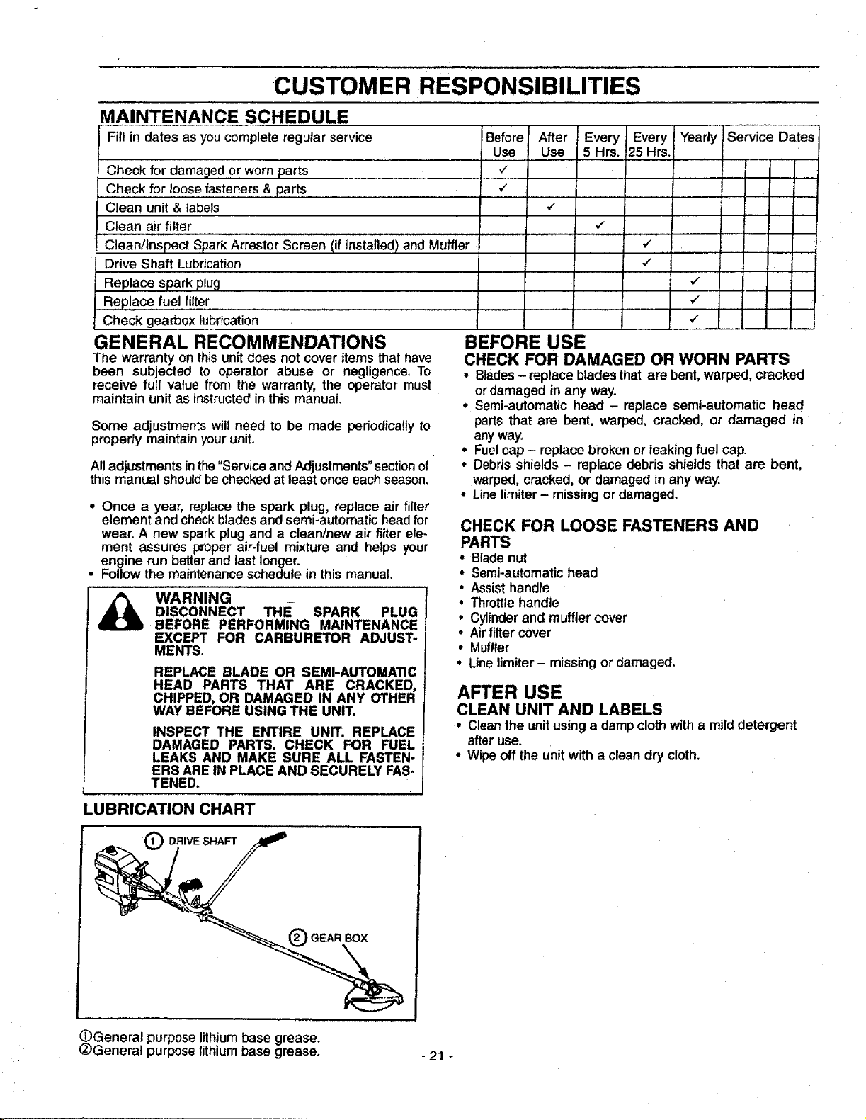
LUBRICATION CHART
DRIVE SHAFT
O GEAR BOx
OGeneral purpose lithium base grease.
_General purposelithium base grease. - 21 -
CUSTOMER RESPONSIBILITIES
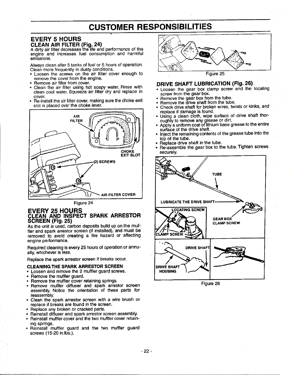
EVERY 5 HOURS
CLEAN AIR FILTER {Fig. 24)
A dirty air filterdecreasesthe lifeand performance of the
engine and increases fuel consumption and harmful
emissions,
Always clean after 5 tanks of fuel or 5 hours of operation,
Clean more frequently in dusty conditions,
• Loosen the screws on the air filter cover enough to
remove the cover from the engine.
• Remove air filter from cover.
• Clean the air filter using hot soapy water. Rinse with
clean cool water,Squeeze air filterdry and replace in
cover,
• Re-installthe airfilter cover,makingsurethe chokeexit
slot is placed over the choke lever.
___"_ _/ AIR FILTER COVER
Figure 24
EVERY 25 HOURS
CLEAN AND INSPECT SPARK ARRESTOR
SCREEN (Fig. 25)
As the unit is used,carbon depositsbuildup on the muf-
fler and spark arrestorscreen (if installed),and must be
removed to avoid creating a fire hazard or affecting
engine performance.
Required cleaningisevery 25 hours ofoperationor annu-
ally,whicheverisless.
Replace the sparkarrestor screen if breaks occur.
CLEANING THE SPARK ARRESTOR SCREEN
• Loosen and removethe 2 mufflerguard screws.
• Remove the mufflerguard.
• Remove the muffler cover retainingspdngs.
• Remove muffler diffuser and spark arrestor screen
assembly. Notice the orientation of these parts for
reassembly.
• Clean the spark arrestor screen with a wire brush or
replace if breaks are found in the screen.
• Replace any broken or crackedparts.
° Reinstall diffuser and spark arrestor screen assembly,
• Reinstall muffler cover and thetwo muffler cover retain-
ing springs,
• Reinstall muffler guard and the two muffler guard
screws (15-20 in.lbs.).
Figure 25
DRIVE SHAFT LUBRICATION (Fig. 26)
• Loosen the gear box clamp screw and the locating
screw fromthe gear box.
: Remove the gear boxfrom thetube.
Remove thedrive shaftfromthe tube.
• Check drive shaft for broken wires,twistsor kinks, and
replace ifdamage is found.
• Using a clean cloth, wipe surface of drive shaft thor-
oughlyto remove any grease or dirt.
• Applya uniformcoatoflithiumbase grease tothe entire
surfaceof the driveshaft.
* Inject theremainingcontentsofthe grease tube intothe
top of thetube,
° Replace drive shaft in the tube.
• Re-assemble the gear box to the tube.Tighten screws
securely,
r._ , ,,,,,,u,,,,,,,,, ................
//4C£J c ,o,so.,w
=,M,so.Ew
Figure 26
- 22
CUSTOMER RESPONSIBILITIES
YEARLY
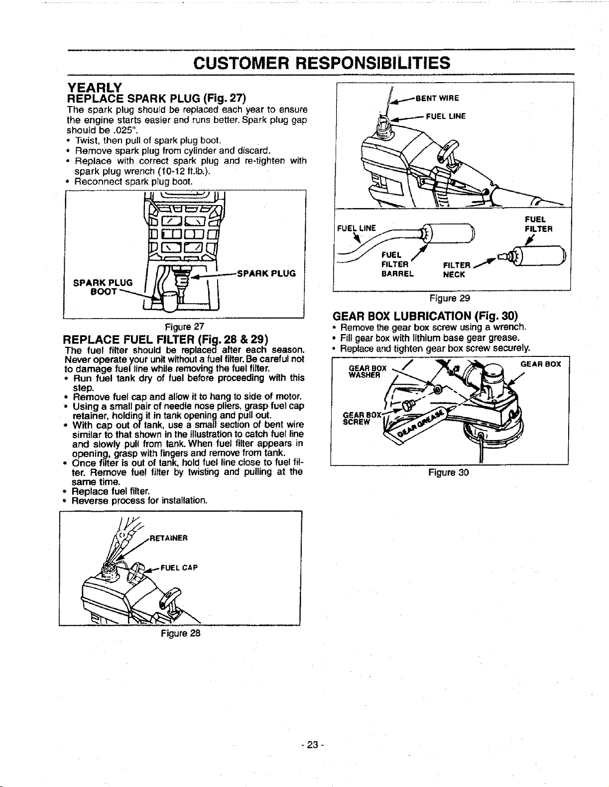
REPLACE SPARK PLUG (Fig. 27)
The spark plug should be replaced each year to ensure
the engine starts easier and runs better. Spark plug gap
should be .025".
• Twist, then pull of spark plug boot.
• Remove spark plug from cylinder and discard.
• Replace with correct spark plug and re-tighten with
spark plug wrench (10-12 flJb.).
• Reconnect spark prug boot.
SPARKBOOTPLUGUG__ _SPARK
PLUG
Figure27
REPLACE FUEL FILTER (Fig. 28 & 29)
The fuel filter should be replaced after each season.
Never operate your unitwithouta fuel filter.Becareful not
to damage fuel line while removingthe fuel filter.
• Run fuel tank dry of fuel before proceeding with this
step.
i emove fuel cap and allowit tohang to side of motor.
Using a small pair ofneedle nose pliers,graspfuel cap
retainer, holdingit in tankopeningano pullout.
With cap out of tank, use a small section of bent wire
similar to that shownin theillustrationto catch fuel line
and stowly pull from tank.When fuel tilter appears in
opening, grasp withfingersand removefrom tank.
• Once filter is out of tank. holdfuet line close to fuel fil-
ter. Remove fuel filter by twisting and pulling at the
same time.
• Replace fuel filter.
• Reverse processfor installation.
•WIRE
FUEL LiNE
FUEL
F,L,," )
BARREL NECK
Figure 29
GEAR BOX LUBRICATION (Fig. 30)
• Removethegear box screwusing a wrench.
• Fill gear box with lithiumbase gear grease.
• Replaceand tighten gear box screw securely.
GEARBOX ,,_J "_i,_m_[..--_ GEARBOX
GEAR BOX
SCREW _
Figure 30
RETA|NER
Figure28
- 23 -
ii i iii ii i iiiiii iiiiiiiii
SERVICE AND ADJUSTMENTS
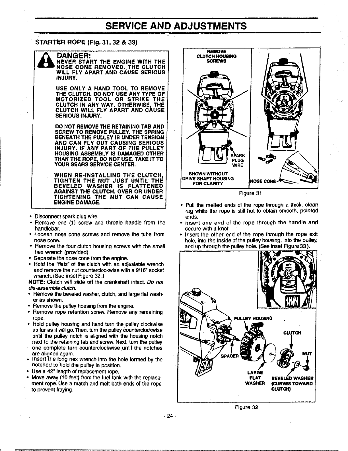
STARTER ROPE (Fig. 31, 32 & 33)
DANGER:
NEVER START THE ENGINE WITH THE
NOSE CONE REMOVED. THE CLUTCH
WILL FLY APART AND CAUSE SERIOUS
INJURY.
USE ONLY A HAND TOOL TO REMOVE
THE CLUTCH. DO NOT USE ANY TYPE OF
MOTORIZED TOOL OR STRIKE THE
CLUTCH IN ANY WAY. OTHERWISE, THE
CLUTCH WILL FLY APART AND CAUSE
SERIOUS INJURY.
DO NOT REMOVE THE RETAININGTAB AND
SCREW TO REMOVE PULLEY. THE SPRING
BENEATH THE PULLEY IS UNDER TENSION
AND CAN FLY OUT CAUSING SERIOUS
INJURY. IF ANY PART OF THE PULLEY
HOUSING ASSEMBLY IS DAMAGED OTHER
THAN THE ROPE, DO NOT USE. TAKE IT TO
YOUR SEARS SERVICE CENTER,
WHEN RE-INSTALLING THE CLUTCH,
TIGHTEN THE NUT JUST UNTILTHE
BEVELED WASHER IS FLATTENED
AGAINST THE CLUTCH. OVER OR UNDER
TIGHTENING THE NUT CAN CAUSE
ENGINE DAMAGE.
• Disconnectsparkplug wire.
• Remove one (1) screw and throttle handle from the
handlebar.
- Loosen nose cone screws and remove the tube from
nose cone.
• Remove the four clutch housingscrews withthe small
hex wrench (provided).
• Separate the noseconefromtheengine.
• Hold the "flats"of the clutchwith an adjustablewrench
and removethenutcounterclockwisewitha 9/16" socket
wrench.(See inset Figure32..)
NOTE: Clutch will slide off the crankshaftintact,Do not
dis-assemb/eclutch.
• Remove the beveledwasher,clutch,andlargeflatwash-
er as shown.
• Remove thepulleyhousingfrom theengine.
• Remove rope retentionscrew.Remove any remaining
rope.
• Hold pulleyhousingand handturn the pulleyclockwise
as far as itwillgo.Then,turnthe pulleycounterclockwise
untilthe pulteynotchis alignedwith the housingnotch
nextto the retainingtab andscrew,Next,turnthe pulley
one complete turn counterclockwiseuntil the notches
are alignedagain.
• insert the long hexwrenchintothe holeformed by the
notched to hold the pulleyinposilion.
• Use a 42" lengthofreplacementrope.
° Move away (10 feet) fromthefuel tankwith thereplace-
ment rope.Use a matchand melt bothends ofthe rope
topreventfraying.
REMOVE
CLUTCH HOUSING
SCREWS
WIRE
SHOWN WITHOUT
DRIVE SHAFT HOUSING
FOR CLARITY
Figure 31
* Pull the melted ends of the ropethrougha thick,clean
rag whilethe rope is stillhot to obtainsmooth, pointed
ends,
• insert one end of the rope through the handle and
securewith a knot,
° Insert the other end of the rope through the rope exit
hole, into the insideof the pulley housing, into the pulley.
and up through the pulleyhole. (See inset Figure33).
PULLEY HOUSING
CLUTCH
LARGE
FLAT
WASHER
BEVELEDWASHER
(CURVESTOWARD
CLUTCH)
- 24 -
Figure 32
ml i iiii i
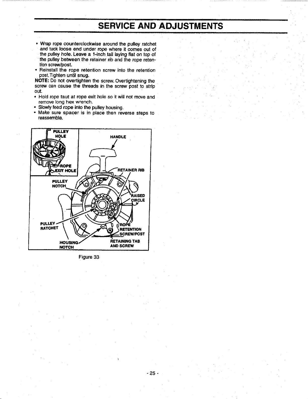
SERVICE AND ADJUSTMENTS
• i ii
• Wrap rope counterclockwise aroundthe pulley ratchet
and tuckloose end under rope where it comes out of
the pulleyhole. Leave a 1-inchtail layingflat on topof
the pulleybetween the retainer rib andthe rope reten-
tionscrew/post.
• Reinstall the rope retention screw into the retention
post.Tightenuntil snug.
NOTE: Do not overtighten the screw.Overtighteningthe
screwcan cause the threads in the screw post to strip
out.
• Hold ropetaut at rope exit hole so il wig not move and
remove long hex wrench.
• Slowlyfeed rope into the pulley housing.
• Make sure spacer is in place then reverse steps to
reassemble.
Figure 33
- 25 -
SERVICE AND ADJUSTMENTS
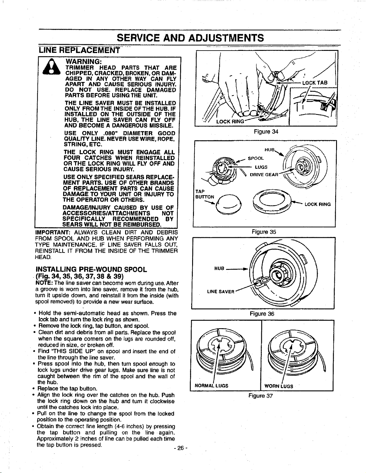
LINE R--E-P-LAC EMEN'r ........
WARNING:
TRIMMER HEAD PARTS THAT ARE
CHIPPED, CRACKED, BROKEN, OR DAM-
AGED IN ANY OTHER WAY CAN FLY
APART AND CAUSE SERIOUS INJURY.
DO NOT USE. REPLACE DAMAGED
PARTS BEFORE USING THE UNIT.
THE LINE SAVER MUST BE INSTALLED
ONLY FROM THE INSIDE OFTHE HUB. IF
INSTALLED ON THE OUTSIDE OF THE
HUB, THE LINE SAVER CAN FLY OFF
AND BECOME A DANGEROUS MISSILE.
USE ONLY .080" DIAMETER GOOD
QUALITY LINE. NEVER USEWIRE, ROPE,
STRING, ETC.
THE LOCK RING MUST ENGAGE ALL
FOUR CATCHES WHEN REINSTALLED
OR THE LOCK RING WILL FLY OFF AND
CAUSE SERIOUS INJURY.
USE ONLY SPECIFIED SEARS REPLACE-
MENT PARTS. USE OF OTHER BRANDS
OF REPLACEMENT PARTSCAN CAUSE
DAMAGE TO YOUR UNIT OR INJURY TO
THE OPERATOR OR OTHERS.
DAMAGE/INJURY CAUSED BY USE OF
ACCESSORIESIATTACHMENTS NOT
SPECIFICALLY RECOMMENDED BY
SEARS WILL NOT BE REIMBURSED.
IMPORTANT: ALWAYS CLEAN DIRT AND DEBRIS
FROM SPOOL AND HUB WHEN PERFORMING ANY
TYPE MAINTENANCE. IF LINE SAVER FALLS OUT,
REINSTALL IT FROM THE INSIDE OF THE TRIMMER
HEAD.
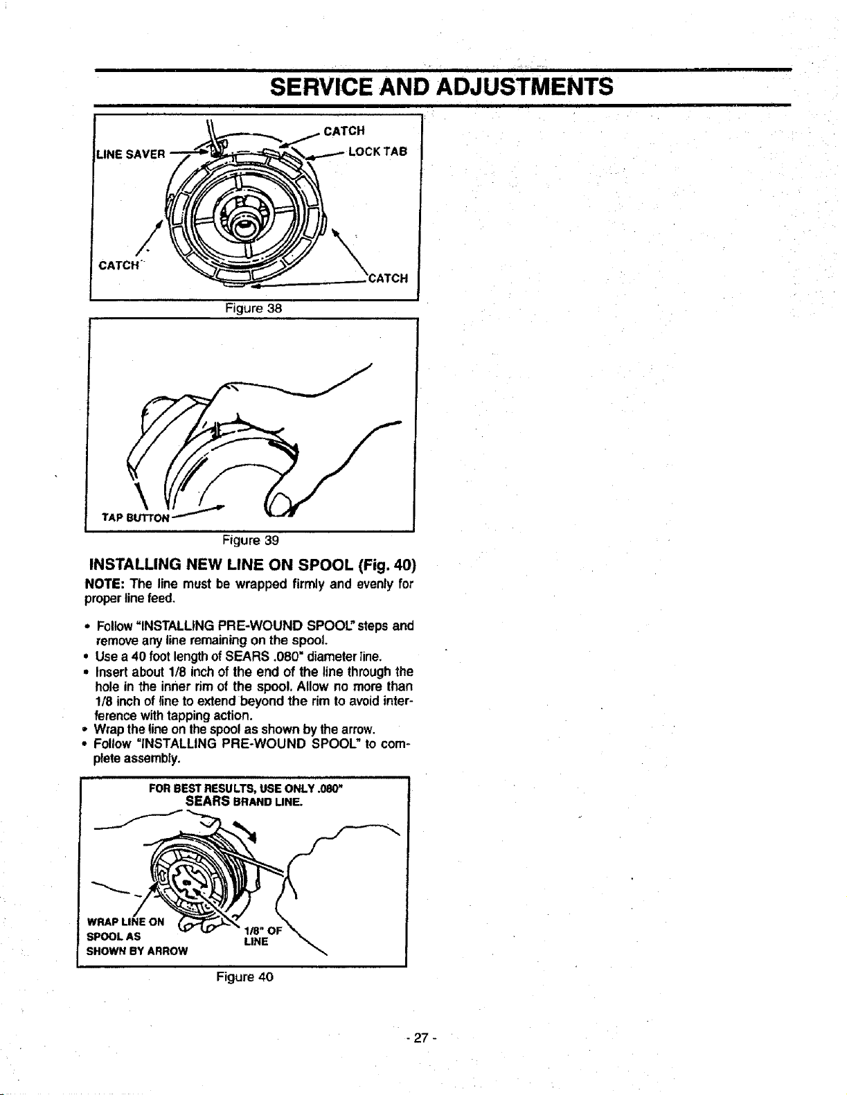
INSTALLING PRE-WOUND SPOOL
(Fig. 34, 35, 36, 37, 38 & 39)
NOTE: The linesaver canbecome wornduring use.After
a groove is worn into line saver, removeit from the hub,
turn it upside down, and reinstall il fromthe inside(with
spoolremoved) to provide a new wearsurface.
• Hold the semi-automatic head as shown. Press the
locktab and turnthe lockring as shown.
• Remove the lock ring,tap button,andspool.
• Clean dirt and debris from all parts.Replacethe spool
when the square corners on the tugs are roundedoff,
reduced insize, or brokenoff.
• Find "THIS SIDE UP" on spool and insertthe end of
the linethrough the linesaver.
• Press spool into the hub, then turnspool enough to
lock lugs under drive gear lugs. Makesure lineis not
caught between the rim of the spooland the wail of
the hub.
° Replacethe tap button.
• Alignthe lock ring over the catcheson the hub. Push
the lock ring down on the hub and turn it clockwise
untilthecatches lockintoplace.
• Pull on the line to change the spoolfrom the locked
positionto the operating position.
• Obtain the correct line length (4-6 inches)by pressing
the tap button and pulling on the Iine again.
Approximately2 inchesof line canbe pulled eachtime
the tap button is pressed. - 26 -
LOCK RING
Figure 34
TAP
DRIVE GEAR__
LOCK RING
Figure 35
NORMAL LUGS WORN LUGS
Figure 37
Figure 36
ill|mr • I iji L i|111 i
SERVICE AND ADJUSTMENTS
• • ,, . , • . , ...m ,..., , ..
LINE SAVER
CATCH
Figure 38
\
TAP BUTTON
Figure 39
INSTALLING NEW LINE ON SPOOL (Fig. 40)
NOTE: The line must be wrapped firmly and evenly for
properlinefeed.
• Follow"INSTALLING PRE-WOUND SPOOL"stepsand
removeanyline remainingon the spool.
. Usea 40 foot lengthofSEARS •080" diametertine.
• Insertabout 1/8 inchof the end of the line throughthe
hole in the inner rimof the spool. Allow no more than
1/8 inchof fine to extend beyond the rim to avoidinter-
ference withtappingaction.
• Wrapthe line on thespoolas shownbythe arrow.
• Follow =INSTALLING PRE-WOUND SPOOL" to com-
pleteassembly.
FOR BEST RESULTS, USE ONLY .080"
SEARS BRAND LINE.
WRAP LINE ON
SPOOL AS
SHOWN BY ARROW
LINE
Figure 40
- 27 -

|1 i iiiii
SERVICE AND ADJUSTMENT
BRUSH
&
BLADE SHARPENING (Fig, 41)
DANGER:
ALWAYS STOP THE ENGINE BEFORE
SHARPENING A BLADE. THE BLADE WILL
CONTINUE TO SPIN AFTER THE ENGINE
STOPSOR AFTER THETHROTTLETRIGGER
HAS BEEN RELEASED. MAKE SURE THE
BLADE HAS STOPPED COASTINGAND DIS.
CONNECT SPARK PLUG 5EFORE PER-
FORMINGWORK ONTHE BLADE.
ALWAYS REPLACE A BLADE THAT IS
BENT, WARPED, CRACKED, OR DAMAGED
IN ANY OTHER WAY. NEVER ATTEMPTTO
STRAIGHTEN AND REUSE A DAMAGED
BLADE. USE ONLY THE SPECIFIED
REPLACEMENT BLADE.
WEAR PROTECTIVE GLOVES WHEN HAN-
DLING OR PERFORMING MAINTENANCE
ONTHE BLADE TO HELP AVOIDINJURY.
TOPREVENTTHE BLADE FROMCRACKING
OR FLYING APART AFTER SHARPENING,
DO NOT RLE WITHIN I/4 INCH OF THE
RADIISHOWN.
, Check bladesfor flatness periodically. Laytheblade
on a fiat surface and inspect the blade for flatness
before sharpening.Throw away any blade that is not
flat.
• File or grindeach edge in the same manner to main-
tain a balanced blade.
BRUSH BLADE
FiLE OR GRIND
BLADEASSHOWN
MAINTA_ RADIUS
IN THISAREA
SHARPENTHIS
AREA ONLY
MAINTAIN RADIUS
IN THIS AREA
WEED BLADE SHARPENING (Fig. 42)
• The 4 point, 8 inch blade is reversible. When the cut-
tingedgeon one sidebecomesdull,turnthe blade over.
When both sides of cutting edges become dull, the
blade may be resharpened,
• Check blades for flatness periodically. Laythe blade
on a flat surface and inspect the blade for flatness
- beforesharpening,throwaway anybladethatisnot Ilat.
• File or grind each edge in the same manner to main-
tain a balanced blade.
WEED BLADE _ FILEORGRIND EACH
EDGEINTHE SAME
MANNER TO MAINTAIN
A BALANCEDBLADE
O
1/4INCH
_--T--_l _ MAINTAINRADIUS
MAINTAINRADIUS'_"-"__._
AREAONLY
Figure 42
Figure 41
- 28 -
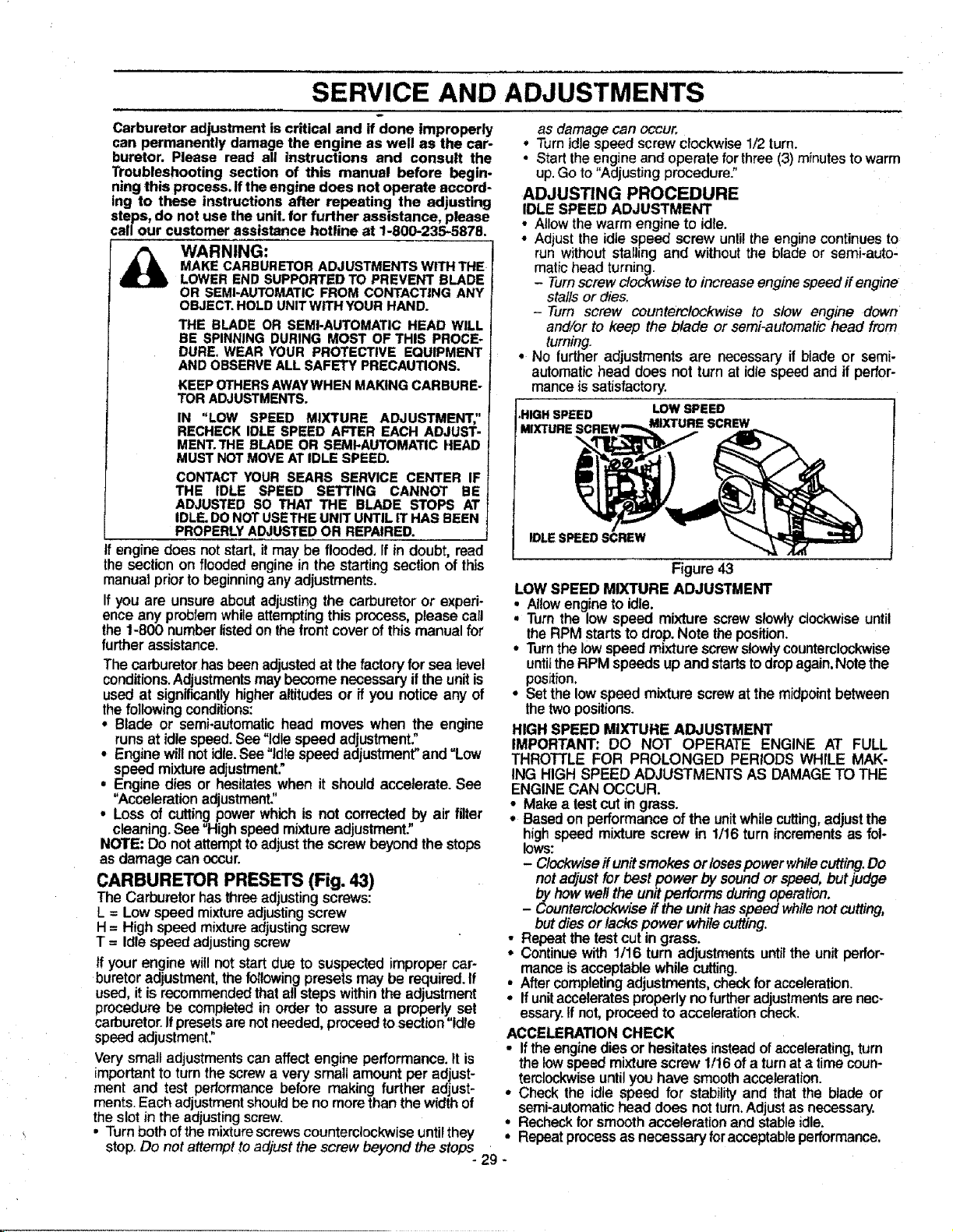
SERVICE AND ADJUSTMENTS
t
Carburetor adjustment iscritical and if done improperly
can permanently damage the engine as well as the car-
buretor. Please read all instructions and consult the
Troubleshooting section of this manual before begin-
ning this process. Ifthe engine does not operate accord-
ing to these instructions after repeating the adjusting
steps, do not use the unit.for further assistance, please
call our customer assistance hotline at !-800-235-5878.
_ WARNING:
MAKECARBURETORADJUSTMENTSWITHTHE
LOWERENDSUPPORTEDTO PREVENTBLADE
OR SEMI-AUTOMATICFROMCONTACTINGANY
OBJECT.HOLDUNITWITHYOURHAND.
THE BLADE OR SEMI-AUTOMATICHEAD WILL
BE SPINNINGDURINGMOST OFTHIS PROCE-
DURE.WEARYOUR PROTECTIVEEQUIPMENT
ANDOBSERVEALLSAFETYPRECAUTIONS.
KEEPOTHERSAWAYWHENMAKINGCARBURE-
TORADJUSTMENTS.
IN "LOW SPEED MIXTURE ADJUSTMENT,"
RECHECKIDLESPEEDAFTER EACH ADJUST-
MENT.THEBLADEOR SEMI-AUTOMATICHEAD
MUSTNOTMOVEATIDLESPEED.
CONTACTYOUR SEARS SERVICE CENTER IF
THE IDLE SPEED SETTING CANNOT BE
ADJUSTEDSO THAT THE BLADE STOPS AT
IDLE.DONOTUSETHEUNITUNTILITHAS BEEN
PROPERLYADJUSTEDOR REPAIRED.
engine does not start, it may be flooded. If in doubt, read
the section on flooded engine in the starting section of this
manual prior to beginning any adjustments.
If you are unsure about adjusting the carburetor or experi-
ence any problem whileattempting this process, please call
the 1-800 number listed on thefront cover of this manual for
further assistance,
The carburetor has been adjusted at the factory for sea level
conditions. Adjustments may become necessaryif the unit is
used at significantly higher altitudes or ff you notice any of
thefollowing conditions:
• Blade or semi.automatichead moves when the engine
runs at idle speed. See "Idle speed adjustment."
• Engine will not idle.See"Idle speed adjustment"and "Low
speed mixture adjustment."
• Engine dies or hesitateswhen it shouldaccelerate. See
"Acceleration adjustment:'
• Loss of cuttingpowerwhichis not corrected,byair filter
cleaning.See "High speedmixtureadjustment:
NOTE: Do notattempttoadjust the screwbeyond the stops
as damage can occur.
CARBURETOR PRESETS (Fig. 43)
The Carburetorhas threeadjusting screws:
L = Low speed mixtureadjustingscrew
H= High speed mixture adjustingscrew
T = Idlespeed adjustingscrew
If yourengine willnot startdue to suspected impropercar-
buretor adjustment,thefollowing presetsmay be required.If
used,itis recommendedthata!lsteps withinthe adjustment
procedure be completedin order to assure a properly set
carburetor.Ifpresetsarenotneeded,proceedtosection"Idle
speed adjustment."
Very small adjustmentscan affectengine performance.It is
importantto turnthescrewa verysmall amountper adjust-
ment and test performancebefore making further adjust-
ments.Each adjustmentshouldbe no morethanthe widthof
the slot in the adjusting screw.
• Turn both ofthe mixturescrews counterclockwise untilthey o
stop. DOnot attempt to adjust the screw beyond the stops
- 29 -
as damage can occur.
• Turnidlespeed screw clockwise 1/2 turn.
• Startthe engine and operate forthree(3) minutesto warm
up.Go to "Adjusting procedure"
ADJUSTING PROCEDURE
IDLE SPEED ADJUSTMENT
• Allow the warmengine to idle.
• Adjust the idle speed screw until the engine continues to
run withoutsta,ing and withoutthe blade or semi-auto:
matichead turning.
- Turnscrew clockwise to increase engine speedif engine
stalls or dies.
-Turn screw counterclockwise to slow engine down
and/or to keep the blade or semi-automatic head from
turning.
• No furtheradjustments are necessary if blade or semi-
automatic head does not turn at idle speed and if perfor-
mance Lssatisfactory.
•HIGH SPEED LOW SPEED
MIXTURE ,_ MIXTURE SCREW
IDLE SPEED SCREW
Figure 43
LOW SPEED MIXTURE ADJUSTMENT
• AUowengineto idle.
• Turn the low speed mixture screw slowlyclockwiseuntil
theRPM starts to drop. Note the position.
• Turnthe low speed mixture screwslowly counterclockwise
untifthe RPM speeds up and startsto drop again.Note the
posit{on.
• Set the low speed mixture screwat the midpoint between
thetwopositions.
HIGH SPEED MIXTURE ADJUSTMENT
IMPORTANT: DO NOT OPERATE ENGINE AT FULL
THROTTLE FOR PROLONGED PERIODS WHILE MAK-
ING HIGH SPEED ADJUSTMENTS AS DAMAGETO THE
ENGINECAN OCCUR.
• Makea test cutin grass.
• Basedon performanceof the unitwhilecutting,adjust the
highspeed mixture screw in 1/16turn incrementsas fol-
lows:
- Clockwiseif unitsmokesor losespower whilecutting.Do
not adjust for best power by sound or speed, butjudge
by how wet/the unit performs during operation.
- Counterclockwise if the unithasspeed whilenot cutting,
butdies or lacks power while cutting.
• Repeatthe test cut in grass.
• Continuewith 1/16 turn adjustments untilthe unit perfor-
mance isacceptable whilecutting.
• After completingadjustments, check for acceleration.
• Ifunitaccelerates properly no further adjustmentsare nec-
essary.If not, proceed to acceleration check.
ACCELERATION CHECK
• Iftheenginediesor hesitatesinsteadofaccelerating, turn
the lowspeed mixture screw 1/16ofa turnat a timecoun-
terclockwiseuntilyou have smoothacceleration.
• Check the idle speed for stabilityand that the btade or
semi-automatichead does notturn.Adjustas necessary.
Recheckforsmoothaccelerationand stableidle.
Repeatprocessas necessary foracceptableperformance.
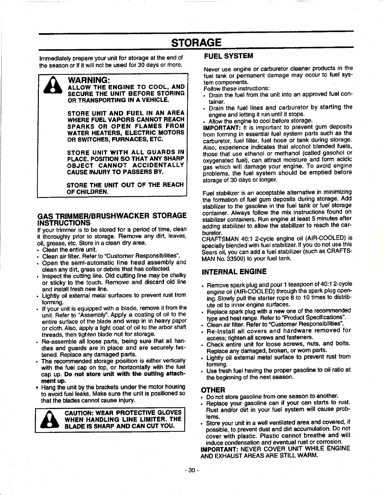
J i Ul i|111 UlU| i • ,lllll|=q ii t i i
STORAGE
iiiiiiii i ii iii ii i i I Ill! i i ii illll | III
Immediatelyprepare yourunitfor storage at the end of FUEL SYSTEM
the seasonor ifitwiltnotbe used for 30 days or more.
WARNING:
ALLOW THE ENGINE TO COOL, AND
SECURE THE UNIT BEFORE STORING
OR TRANSPORTING IN A VEHICLE.
STORE UNIT AND FUEL IN AN AREA
WHERE FUEL VAPORS CANNOT REACH
SPARKS OR OPEN FLAMES FROM
WATER HEATERS, ELECTRIC MOTORS
OR SWITCHES, FURNACES, ETC.
STORE UNIT WITH ALL GUARDS IN
PLACE. POSITION SO THAT ANY SHARP
OBJECT CANNOT ACCIDENTALLY
CAUSE INJURY TO PASSERS BY.
STORE THE UNIT OUT OF THE REACH
OF CHILDREN.
GAS TRIMMER/BRUSHWACKER STORAGE
INSTRUCTIONS
If yourtrimmer isto be storedfor a period oftime, clean
it thoroughlyprior to storage. Remove any dirt, leaves,
oi!,grease, etc. Store in a clean dry area.
• Clean theentire unit.
• Clean air filter.Refer to=Customer Responsibilities".
• Open the semi-automatic line head assembly and
clean any dirt,grass or debds that hascollected.
• Inspectthe cuttingline. Old cutting line may be chalky
or sticky to the touch. Remove and discard old line
and installfresh new line.
• Lightlyoilexternal metal surfaces to prevent rustIrom
forming.
• If yourunitis equippedwith a blade, remove itfromthe
unit. Refer to "Assembly".Apply a coating of oi! to the
entire surface ofthe blade and wrap in in heavy paper
or cloth.Also, apply a light coat of oit tothe arborshaft
threads, then tighten blade nut for storage.
• Re-assemble all loose parts, being sure that all han-
dles and guards are in place and are securely fas-
tened. Replace any damaged parts.
• The recommended storage position is either vertically
with the fuel cap on top, or horizontally with the rue!
cap up. Do not store unit with the cuffing attach-
ment up.
• Hang the unitbythe brackets under the motorhousing
to avoid fuel leaks. Make sure the unitis positionedso
that the bladescannot cause injury.
A........... Ij CAUTION: WEAR PROTECTIVE GLOVES
WHEN HANDLING LINE LIMITER. THE
BLADE IS SHARP AND CAN CUT YOU.
Never use engine or carburetor cleaner productsin the
fuel tank or permanent damage may occur to fuel sys-
tem components.
Followthese instructions:
• Drainthe fuel from the unitintoan approvedfuel con-
tainer.
• Drain the fuel lines and carburetor by starting the
: engineand letting it rununtilitstops.
• Allowthe engine to coolbefore storage.
IMPORTANT: It is important to prevent gum deposits
from forming in essentialfuel system parts such as the
carburetor, fuel filter, fuel hose or tank during storage.
Also, experience indicates that alcohol blended fuels,
those that use ethanol or methanol (called gasohol or
oxygenated fuel), can attract moisture and form acidic
gas which will damage your engine. To avoid engine
problems, the fuel system should be emptied before
storageof 30 days or longer.
Fuel stabilizer isan acceptable alternative in minimizing
the formation of fuel gum deposits during storage. Add
stabilizer to the gasolinein the fuel tank or fuel storage
container. Always follow the mix instructionsfound on
stabilizercontainers.Run engine at least 5 minutesafter
addingstabilizerto allow the stabilizer to reach the car-
buretor.
CRAFTSMAN 40:1 2-cycle engine oil (AIR-COOLED) is
specially blended withfuel stabilizer.If you do not usethis
Sears oil, you can add a fuel stabilizer (suchas CRAFTS-
MAN No,33500) to yourfuel tank.
INTERNAL ENGINE
• Remove sparkplugand pour 1 teaspoonof40:1 2-cycle
engine oil (AIR-COOLED) throughthe spark plugopen-
ing. Slowlypullthe starter rope 8 to 10 timesto distrib-
ute oilto Innerengine surfaces.
• Replacespark plugwitha new one of the recommended
typeandheatrange. Referto "Product Specifications".
• Clean air filter. Refer to "Customer Responsibilities".
• Re-install all covers and hardware removed for
access; tightenall screwsand fasteners.
• Check entire unit for loose screws, nuts, and bolts.
Replaceany damaged, broken, or worn parts.
• Lightlyoil extemal metal surface to prevent rust from
forming.
• Use fresh fuel havingthe proper gasoline tooil ratioat
the beginningofthe nextseason.
OTHER
- Do notstore gasolinefrom one season toanother.
• Replace your gasoline can if your can starts to rust.
Rust and/or dirt in your fuel system will cause prob-
lems.
• Storeyour unitin a well ventilated area and covered, if
possible,topreventdustand dirtaccumulation.Do not
cover with plastic. Plastic cannot breathe and will
inducecondensationand eventual rust or corrosion.
IMPORTANT: NEVER COVER UNIT WHILE ENGINE
AND EXHAUST AREAS ARE STILL WARM.
-30.

iiii iiii i i ....
TROUBLE SHOOTING POINTS
iii el i iii = H =H== = H =I=====H== =n,== ........
TROUBLE SHOOTING CHART
SYMPTOM CORRECTION
Engine willnot start or
wil!run only for a
few seconds after
starting.
,,j ,
1. Fuel tank empty.
2. Engine flooded.
3. Spark plug not firing,
4. Fuel not reaching carburetor.
5. Carburetor requires adjustment.
6. None of the above.
Engine willnot
idle properly.
1. Carburetor set too fasi or too slow.
2. Carburetor requires adjustment.
3. None of the above.
Engine wili not 1. Air filter dirty.
accelerate, lacks 2. Spark plug fouled.
power,or dies
under a load. 3. Carburetor requires adjustment.
4. Muffler outlets plugged.
5. None of the above.
Engine !. Airfilter dirty.
Smokes 2. Fuel mixture incorrect.
excessively, 3. Carburetor requiresadjustment.
Engine
runs hot
Cutting head
stopsunder a load
or does not turn when
engine is accelerated,
_L
1. Fuel mixtureincorrect.
2. Spark plug incorrect.
3. Carburetorset too high (lean).
4. WrongdiametercuttingIine.(too large)
5. None ofthe above.
Line doesnot
advance or breaks
whilecutting.
Line weldsonto
spool.
Line purlsback
into head.
'i. Driveshaftnot engaged.
2. Driveshaftbroken,
1. Line improperiY';outedin head.
2. Line improperly wound onto spool.
3. Line size incorrect,
4. Old cuttingline.
5, Too littleline outside head.
6. Dirt accumulated in cover.
7. Line woundin wrong direction.
,,, ,.,,, ,,
1. Line size incorrect.
2. Old cuttingline.
3. Incorrect spool.
4. Crowding line against material
being cut.
,,ml i ,, i, i,,,,,,,i i,i ii, i
1 Too litUeline outside of head.
2. Old cuttingline.
1. Filltankwith correctfuel mixture.
2. See "Starting Instructions".
3. InstalJnew plug/check ignitionswitch.
4. Reptace fuel filter; inspectfuel line.
5. See "Carburetor Adjustments."
6. Contact your SEARS Service Center/Dept.
1.See "Carburetor Adjustments."
2. See "Carburetor Adjustments."
3. Contact your SEARS Service Center/Dept.
1. Clean or replace air filter.
2. Clean or replace spark ptug and re-gap.
3. See "Carburetor Adjustments."
4. Contact your SEARS Service Center/Dept,
i 5. Contact your SEARS Service Center/Dept,
1.Clean or replace air filter.
2. Refuel with correct fuel mixture.
3. See "Carburetor Adjustments."
1, See' "Fueling'"-Your Unit."
2. Replace with correct plug.
3. See Carburetor Adjustments."
4. Use only .080 "diameter cutting line.
_.Contact your SEARS Service Center/Dept.
1. See "Assembly," "Tube", insert fully.
2. Contact your SEARS Service Center/Dept.
t. Remove cover. Check linerouting.-_--
2. rewindline tightlyand evenly.
3. Useonly.080" diameter line,
4. Replace with new cutting line.
5. Remove cover. Pull4" of lineto outside.
6, Clean cover.
7. Rewindin correctdirection.
1, Use only.080" diameter line,
2. Replace with new cutting line.
3. Use properspool.
4. Cut withtip of line.
5. Reduce cuttingspeed.
,, ,,,, i i
1. Remove cover. Pull 4" of line to outside.
2. Replace with new cuttingline.
If situationsoccurwhichare not covered in this manua usecare and good judgemenL
Ifyou need assistance, contact your SEARS ServiceCenter/Department or the
CUSTOMER ASSISTANCE HO TLINE AT 1-800-235-5878.
- 31 -
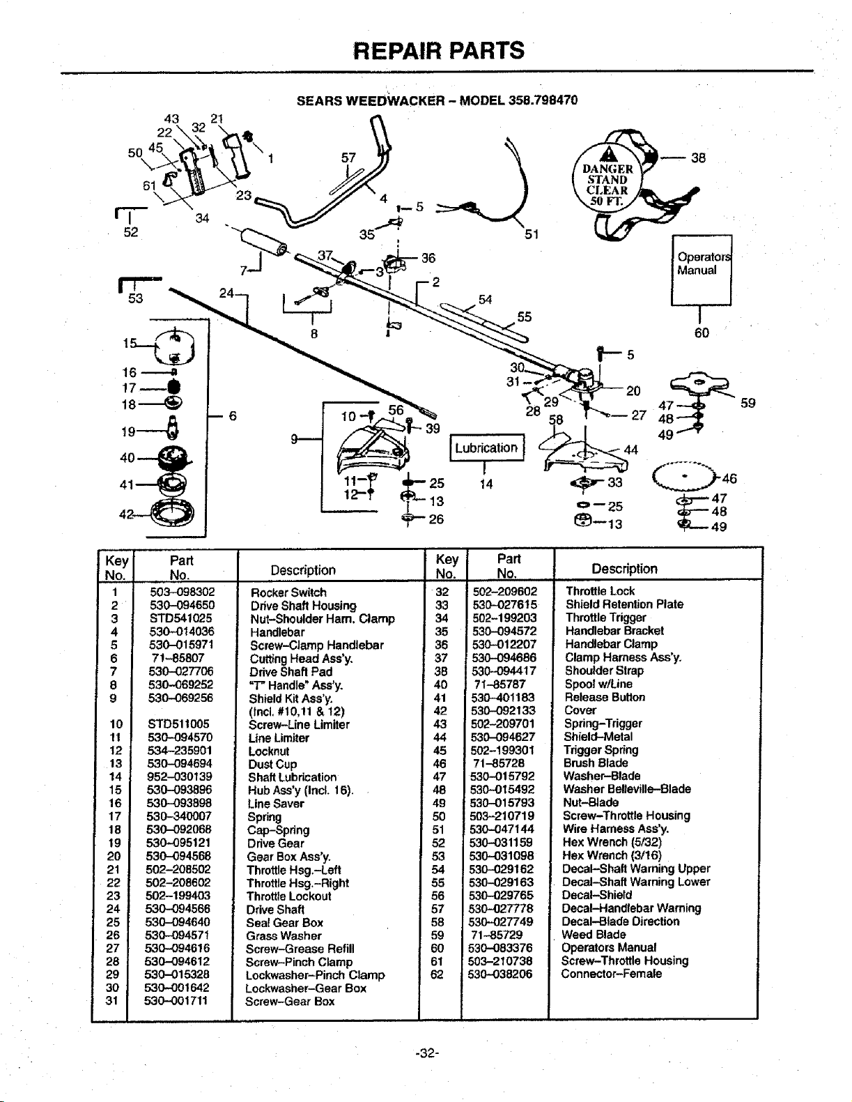
REPAIR PARTS
SEARS WEEDWACKER - MODEL 358.798470
54
55
I Lubrication I
I
14
Operator_
Manual
f
60 •
f,-s
27 48
4
44
59
Key Part
No. No.
1 503-098302
2 530--094650
3 STD541025
4 530-,-014036
5 530-015971
6 71,-85807
7 530--027706
8 530-069252
9 530-069256
10 STD511005
11 530-094570
t2 534-235901
13 530-094694
14 952-030139
15 530-093896
16 530-093898
17 530-340007
18 530-092o68
19 530-095121
20 530-094568
21 502-208502
22 502-208602
23 502-199403
24 530-094566
25 530-094640
26 530-094671
27 530-094616
28 530,--094612
29 5-30--015328
30 530-001642
31 530--001711
Description
HH,, u
RockerSwitch
DriveShaft Housing
Nut-Shoulder Ham, Clamp
Handlebar
Screw-Clamp Handlebar
Key
No.
32
33
34
35
36
Part
No.
502-209602
530-027615
502-199203
530-094572
530-012207
Description
Throttle Lock
Shield Retention Plate
Throttle Trigger
Handlebar Bracket
Handlebar Clamp
Cutting Head Ass'y.
Drive Shaft Pad
"T" Handle"Ass'y.
Shield Kit Ass'y.
(lncl, #10,11 & 12)
Screw-Line Limiter
LineLimiter
Locknut
DustCup
Shaft Lubrication
Hub Ass'y (Incl. 16).
Line Saver
Spring
Cap-Spring
Drive Gear
Gear Box Ass'yo
ThrottleHsg.-Left
ThrottleHsg.-Right
ThrottleLockout
DriveShaft
Seat Gear Box
Grass Washer
Screw-Grease Refill
Screw-Pinch Clamp
Lockwasher-Pinch Clamp
Lockwasher-Gear Box
Screw-Gear Box
37
3B
40
41
42
43
44
45
46
47
48
49
5O
51
52
53
54
55
56
57
58
59
60
61
62
530-094686
530-094417
71-.85787
530.40!183
530--092133
502-209701
530-094627
502-199301
71-85728
530-0t 5792
530-015492
530-015793
503210719
530-047144
530-031159
530-031098
530-029162
530-029163
530-029765
530-027778
530-027749
71-85729
530-083376
503-210738
530-038206
Clamp HarnessAss'y.
Shoulder Strap
Spool w/Line
Release Button
Cover
Spring-Trigger
Shield-Metal
TriggerSpring
Brush Blade
Washer-Blade
Washer Befieville--Blade
Nut-Blade
Screw-Throttle Housing
Wire Harness Ass'y,
Hex Wrench (5/32)
Hex Wrench(3/t6)
Decal-Shaft Warning Upper
Decal-Shaft Warning Lower
Decal-Shield
Decal-Handlebar Warning
Decal-Blade Direction
Weed Blade
Operators Manual
Screw-Throttle Housing
Connector-Female
-32-
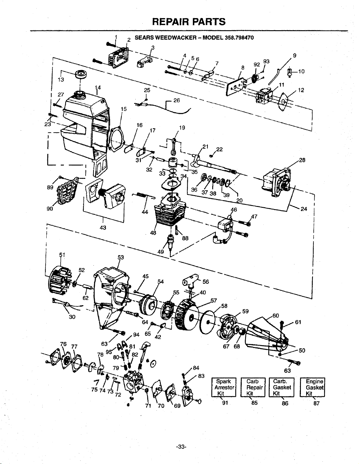
REPAIR PARTS
16 19
_ _ 17
!
I --_
/22
[ "
43
52
32
44
48
45
54
37 38
3O
59
61
76 77
67 68
63
,sp rca
I Arrestor_ | Gasket I
91 85 86 87
-33-
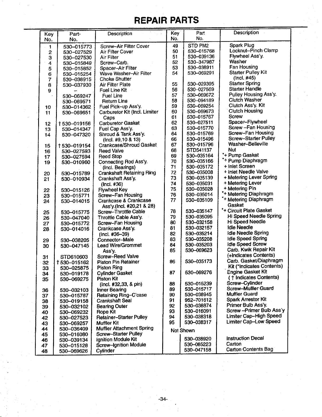
Key
No.
1
2
3
4
5
6
7
: 8
9
10
11
12
t3
14
15
16
17
19
20
21
22
23
24
25
26
27
28
29
30
Part-
No.
,,L
530-015773
530-027529
530-027530
530-015849_
530-015852
530-015254
530-038915
530-037930
530-069247
530-069571
530-014362
530-069651
REPAIR PARTS
i ,,,,HI I I ,lllll I I=,
Description Ke_ Part Description
t 530-O19156
530-014347
530-047320
t530-019154
530-027593
530-027594
530-010960
530-015789
530-010934
530-015126
530--015771
530-014015
530-015775
530-047040
530-015772
530-014016
530-038205
530-047145
31 STD610603
32 !t530-015162
33 530-025875
34 530-019178
35 530-069275
36 530-032103
37 530-015787
38 530-019158
39 530-0321O2
40 530-069232
42 530-027523
43 530-069257
44 530-036409
45 530-016080
46 530-039134
47 530-015128
48 530-069626
Screw-Air Filter Cover
AirFilterCover
Air Filter
Screw-Carb.
Spacer-Air Filter
Wave Washer-Air Filter
Choke Shutter
Air Filter Plate
Fuel Line Kit
Fuel Line
Return Line
Fuel Pick-up Ass'y.
Carburetor Kit (incL Limiter
Caps
Carburetor Gasket
Fuel Cap Ass'y.
Shroud & Tank Ass'y.
(Incl. #9,10 & 13)
CrankcaselShroud Gasket
Reed Valve
Reed Stop
Connecting Rod Ass'y.
(IncJ. Bearings)
Crankshaft Retaining Ring
Crankshaft Ass'y.
(Incl. #36)
Flywheel Key
Screw-Fan Housing
Crankcase & Crankcase
Ass'y.(IncI. #20,21 & 28)
Screw-Throttle Cable
Throttle Cable Ass'y.
Screw-Fan Housing
CrankcaseAss'y.
(Incl. #36-39)
Connector-Male
Lead Wire/Grommet
Assay,
Screw-Reed Valve
PistonPin Retainer
PistonRing
CylinderGasket
PistonKit
(Incl. #32,33, & pin)
Inner Beating
Retaining Ring-C'case
Crankshaft Seal
Beadng Outer
Rope Kit
Retainer-Starter Pulley
Muffler Kit
_ilufflerAttachment Spring
Screw-Starter Pulley
ignition Module Kit
Screw-Ignition Module
Cylinder .....
NO.
49
5O
51
52
53
54
55
56
57
58
59
60
61
62
63
64
66
67
68
69
70
71
72
73
74
75
76
77
78
79
80
81
82
83
84
85
86
87
88
89
90
91
92
93
94
95
Not
NO,
STD PM2
530-015768
530-039 t 36
530-347987
530-038911
530-069291
530-029395
530-027569
530-069672
530-O94189
530-069254
530-069673
530-015767
530-027511
530-015770
530-015769
530-O15496
530-015796
STD541137
530-035164
530-035166
530-035172
53O-O35OO8
530-035139
530-035031
530-035028
530-035014
530-035109
530-035147
530-035095
530-032158
530-032157
530-035214
530-035208
530-035203
530-069623
530-035173
530-069276
530-015239
530-015717
530-038945
952-701612
530-038874
530-016091
530-O38318
530-038317
Shown
530-03892O
530--085223
530-047158
Spark Plug
Locknut-Pinch Clamp
Flywheel Ass'y.
Washer
Fan Housing
Starter Pulley Kit
(Incl. #45)
Starter Spring
Starter Handle
PulleyHousingAss'y.
ClutchWasher
ClutchAss'y. Kit
ClutchHousing
Screw
Spacer-Flywheel
Screw-Fan Housing
Screw-Fan Housing
Screw-Starter PulIey
Washer-Belleville
Nut
*+ Pump Gasket
*+ Pump Diaphragm
+ Inlet Screen
+ Inlet Needle Valve
+ Metering Lever Spring
+ Metering Lever
+ Metedng Pin
*+ Metering Diaphragm
*+ Metering Diaphragm
Gasket
*+ Circuit Plate Gasket
Hi Speed Needle Spring
Hi Speed Needle
Idle Needle
IdleNeedle Spring
Idle Speed Spring
Idle Speed Screw
Garb. Kwik Repair Kit
(+indicatesContents)
Carb. Gasket/Diaphragm
Kit (*Indicates Contents)
Engine Gasket Kit
( 1"Indicates Contents)
Screw-Cylinder
Screw-Mullter Guard
Muffler Guard
Spark Arrestor Kit
Primer BulbAss'y.
Screw -Primer BulbAss'y
LimiterCap-High Speed
LimiterCap-Low Speed
InstructionDecal
Carton
Carton Contents Bag
,l,,,
,34-