
Operator's Manual
®
CRRFTSMRN
24cc 2-Cycle Engine
17 Inch Cutting Path/.080 In. Line
GASOLINE BRUSHWACKER ®
Model No.
358.742470
_ ANGER:
Read and follow all Safety Rules and Operating
Instructions before first use of this product.
_) For answers to your questions about this product:
Call 7 am-7 pm, Mon-Sat; Sun, 10 am-7 pm
1-800-235-5878 (Hours listed are Central Time)
Sears, Roebuck and Co., Hoffman Estates, IL 60179 USA
530088637 11/15/99

Warranty Statement 2 Storage 15
Safety Rules 2 Troubleshooting Chart 16
Assembly 5 Emissions Statement 16
Operation 8 Parts List 18
Maintenance 12 Spanish 21
Service & Adjustments 13 Parts and Ordering Back
FULL ONE YEAR WARRANTY ON CRAFTSMAN GAS POWERED
BRUSHWACKER ® BLADED TRIMMER.
For one year from the date of purchase, when this Craftsman Gas Powered
Brushwacker is maintained, lubricated and tuned up according to the operating
and maintenance instructions in the Operator's Manual, Sears will repair, free of
charge, any defect in materials or workmanship.
This warranty excludes the blade, nylon line, spark plug, and air filter, which are
expendable parts and become worn during normal use.
If this Brushwacker is used for commercial purposes, this warranty applies for only
90 days from the date of purchase. If this Brushwacker is used for rental purposes,
this warranty applies for only 30 days from the date of purchase. This warranty ap-
plies only while this product is in use in the United States.
WARRANTY SERVICE IS AVAILABLE BY RETURNING THE BRUSHWACKER TO THE
NEAREST SEARS SERVICE CENTER IN THE UNITED STATES.
This warranty gives you specific legal rights, and you may also have other rights
which vary from state to state.
Sears, Roebuck and Co., 0/817 WA Hoffman Estates, IL 60179
DANGER: This power tool can be
dangerous! This unit can cause serious
injury including amputation or blindness
to the operator and others. The warn-
ings and safety instructions in this man-
ual must be followed to provide reason-
able safety and efficiency in using the
unit. The operator is responsible for fol-
lowing the warnings and instructions in
this manual and on the unit. Read the
entire Operator's Manual before assem*
bling and using the unit! Restrictthe use
of this unit to persons who read, under-
stand, and follow the warnings and in-
structions in this manual and on the unit.
Never allow children to use this unit.
A__ __
_WARNING: Follow all warnings
and instructions. Failure to do so can
result in serious injury.
_, DANGER: Blade can thrust vio-
lently away from material it does not
cut. Blade thrust can cause amputa-
tion of arms or legs. Keep people and
animals 50 feet (15 meters) away.
2
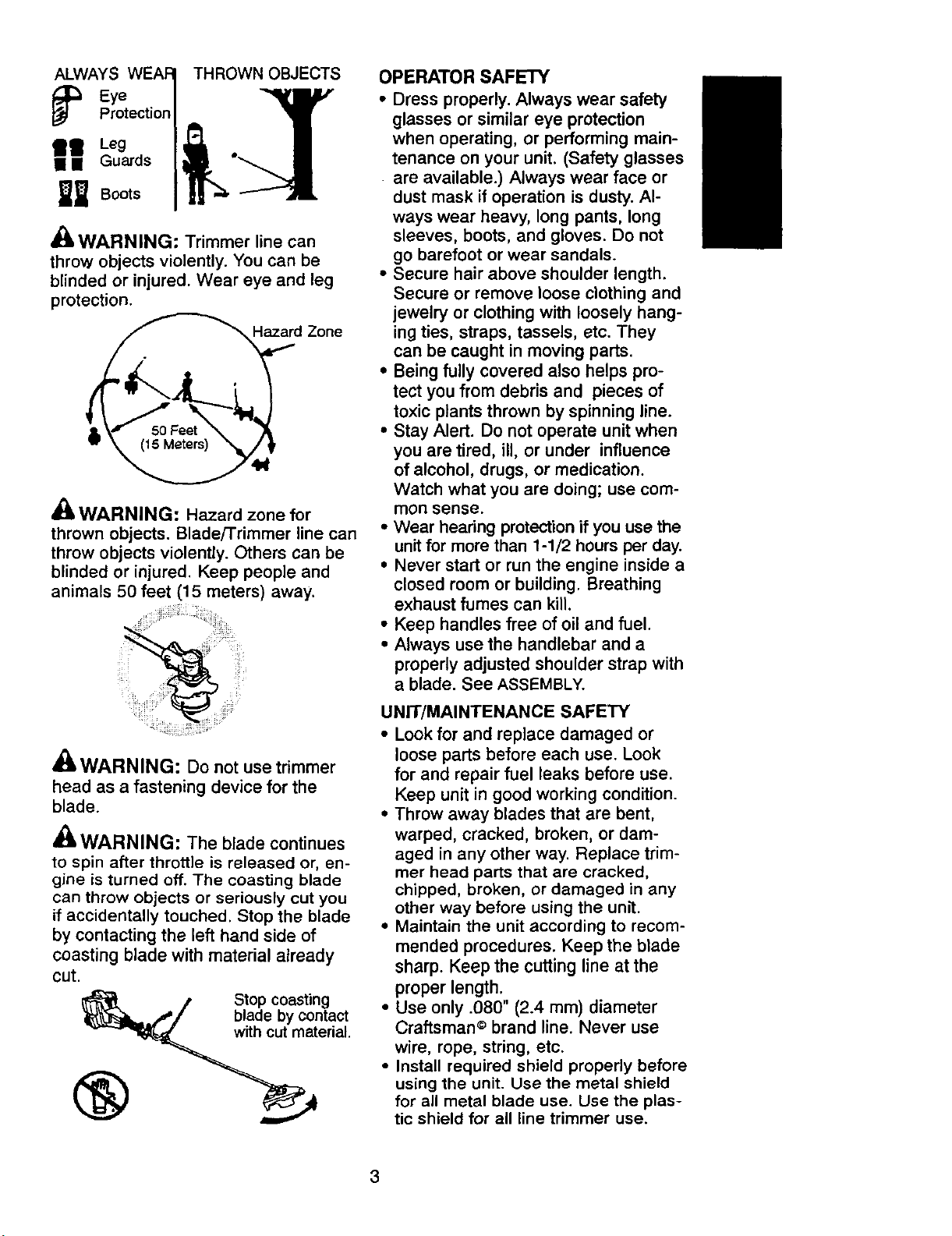
ALWAYS THROWN OBJECTS
Eye 1
" r° tecticn/ .li
Boots | I! _ --'----
_k WARNING: Trimmer line can
throw objects violently. You can be
blinded or injured. Wear eye and leg
protection.
d Zone
A
dBt,WARNING: Hazard zone for
thrown objects. Blade/Trimmer line can
throw objects violently. Others can be
blinded or injured. Keep people and
animals 50 feet (15 meters) away.
A
41WARNING: Do not use trimmer
head as a fastening device for the
blade.
_IL WARNING: The blade continues
to spin after throttle is released or, en-
gine is turned off. The coasting blade
can throw objects or seriously cut you
if accidentally touched. Stop the blade
by contacting the left hand side of
coasting blade with material already
cut.
Stop coasting
blade by contact
with cut material.
®
OPERATOR SAFETY
• Dress properly. Always wear safety
glasses or similar eye protection
when operating, or performing main-
tenance on your unit. (Safety glasses
are available.) Always wear face or
dust mask if operation is dusty. Al-
ways wear heavy, long pants, long
sleeves, boots, and gloves. Do not
go barefoot or wear sandals.
• Secure hair above shoulder length.
Secure or remove loose clothing and
jewelry or clothing with loosely hang-
ing ties, straps, tassels, etc. They
can be caught in moving parts.
• Being fully covered also helps pro-
tect you from debris and pieces of
toxic plants thrown by spinning line.
• Stay Alert. Do not operate unit when
you are tired, ill, or under influence
of alcohol, drugs, or medication.
Watch what you are doing; use com-
mon sense.
• Wear hearing protection if you use the
unit for more than 1-1/2 hours per day.
• Never start or run the engine inside a
closed room or building. Breathing
exhaust fumes can kill.
• Keep handles free of oil and fuel.
• Always use the handlebar and a
properly adjusted shoulder strap with
a blade. See ASSEMBLY.
UNIT/MAINTENANCE SAFETY
• Look for and replace damaged or
loose parts before each use. Look
for and repair fuel leaks before use.
Keep unit in good working condition.
• Throw away blades that are bent,
warped, cracked, broken, or dam-
aged in any other way. Replace trim-
mer head parts that are cracked,
chipped, broken, or damaged in any
other way before using the unit.
• Maintain the unit according to recom-
mended procedures. Keep the blade
sharp. Keep the cutting line at the
proper length.
• Use only .080" (2.4 mm) diameter
Craftsman © brand line. Never use
wire, rope, string, etc.
• Install required shield properly before
using the unit. Use the metal shield
for all metal blade use. Use the plas-
tic shield for all line trimmer use.
3

• Use only specified blade or trimmer
head; make sure it is properly in-
stalled and securely fastened.
• Never start engine with clutch shroud
removed. The clutch can fly off and
cause serious injury.
• Be sure blade or trimmer head stops
turning when engine idles.
• Disconnect the spark plug before
performing maintenance (except car-
buretor adjustments).
• Make carburetor adjustments with
the lower end supported to prevent
the blade ortrimmer line from con-
tacting any object. Hold the unit by
hand; do not use the shoulder strap
for support.
• Keep others away when making car-
buretor adjustments.
• Use only recommended Craftsman
accessories and replacement parts.
• Have all maintenance and service
not explained in this manual per-
formed by a Sears Service Center.
FUEL SAFETY
• Mix and pour fuel outdoors.
• Keep away from sparks or flames.
• Use a container approved for fuel.
• Do not smoke or allow smoking near
fuel or the unit or while using the unit.
• Wipe up all fuel spills before starting
engine.
• Move at least 10 feet (3 meters) away
from fueling site before starting engine.
• Stop engine and allow itto cool be-
fore removing fuel cap.
• Empty the fuel tank before storing
the unit. Use up fuel left in the carbu-
retor by starting the engine and let-
ting it run until it stops.
• Store unitand fuel in an area where
fuel vapors cannot reach sparks or
open flames from water heaters, elec-
tric motorsor switches, furnaces, etc.
CU'I-rlNG SAFETY
• Inspect the area to be cut before
each use. Remove objects (rocks,
broken glass, nails, wire, string, etc.)
which can be thrown or become en-
tangled in the blade or trimmer head.
• Keep others including children, ani-
mals, bystanders, and helpers at
least 50 feet (15 meters) away. Stop
the engine immediately if you are ap-
proached.
• Always keep engine on the right-
hand side of your body.
• Hold the unit firmly with both hands.
• Keep firm footing and balance. Do
not overreach.
• Keep blade or trimmer head below
waist level,
• Do not raise engine above your waist.
• Keep all parts of your body away
from blade, trimmer head, and muf-
fler when engine is running.
• Cut from your right to your left.
• Use only for jobs explained in this
manual.
TRANSPORTING AND STORAGE
• Stop the unit before carrying.
• Keep muffler away from your body.
• Allow engine to cool and secure unit
before storing or transporting it in a
vehicle.
• Empty the fuel tank before storing or
transporting the unit. Use up fuel left
in the carburetor by starting the en-
gine and letting it run until it stops.
• Store unit and fuel in an area where
fuel vapors cannot reach sparks or
open flames from water heaters,
electric motors or switches, furnaces,
etc.
• Store unit so the blade or line limiter
cannot accidentally cause injury. The
unit can be hung by the tube.
• Store unit out of reach of children.
SPECIAL NOTICE: This unitis not
equipped with a temperature limiting
muffler and spark arresting screen
which meets the requirements of Cali-
fornia Codes 4442 and 4443. All U.S.
forest land and the states of California,
Idaho, Maine, Minnesota, New Jersey,
Oregon, and Washington require by
law that many internal combustion en-
gines be equipped with a spark arres-
tor screen. If you operate in a locale
where such regulations exist, you are
legally responsible for installing and
maintaining the operating condition of
these parts. Failure to do so is a viola-
tion of the law. Refer to the MAINTE-
NANCEsection in this manual.
SPECIAL NOTICE: Exposure to vibra-
tions through prolonged use of gaso-
line powered hand tools could cause
blood vessel or nerve damage in the
fingers, hands, and joints of people
prone to circulation disorders or abnor-
mal swellings. Prolonged use in cold
weather has been linked to blood ves-
4
sel damage in otherwise healthy
people. If symptoms occur such as
numbness, pain, loss of strength,
change in skin color or texture, or loss
of feeling in the fingers, hands, or
joints, discontinue the use of this tool
and seek medical attention. An anti-
CARTON CONTENTS
vibration system does not guarantee
the avoidance of these problems. Us-
ers who operate power tools on a con-
tinual and regular basis must monitor
closely their physical condition and the
condition of this tool.
Check carton contents against the fol-
lowing list.
Model: 358.7'42470
• Brushcutter
• Handlebar screws (2)
• Blade shield screws (4)
• Cupped washer
• Large nut for installing blade
• Long hex wrench
• Short hex wrench
• Bracket cover
• Metal shield
• Plastic shield
• Shoulder strap with warning
• Weed blade
• Trimmer head
• Handlebar
• Container of oil
Examine parts for damage. Do not use
damaged parts.
NOTE: If you need assistance or find
that parts are missing or damaged, call
1-800-235-5878.
It is normal for the fuel filter to rattle in the
empty fuel tank.
Finding fuel or oil residue on muffler is
normal due to carburetor adjustments
and testing done by the manufacturer.
ASSEMBLY
WARNING: If received as-
sembled, repeat all steps to ensure your
unit is properly assembled and all fas-
teners are secure.
TOOLS REQUIRED
• 2 hex wrenches (provided)
• adjustable wrench or large pliers
• phillips screwdriver
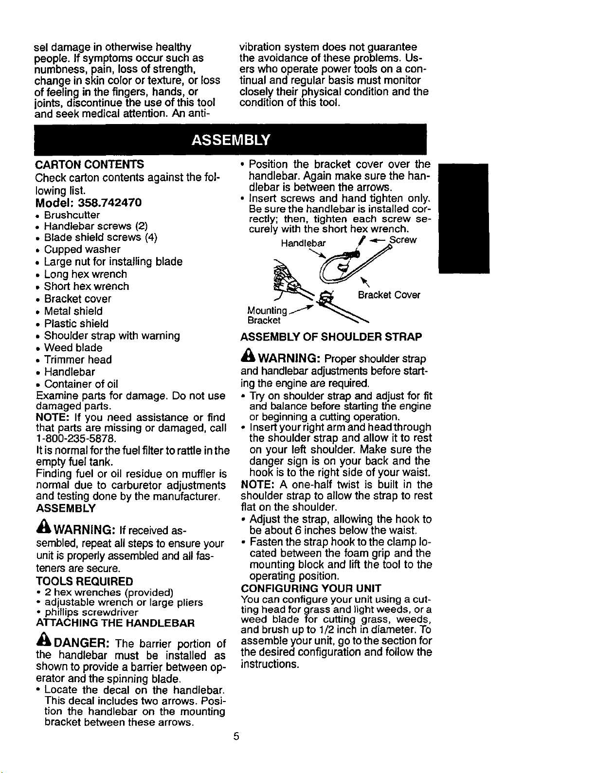
ATTACHING THE HANDLEBAR
DANGER: The barrier portion of
the handlebar must be installed as
shown to provide a barrier between op-
erator and the spinning blade.
• Locate the decal on the handlebar.
This decal includes two arrows. Posi-
tion the handlebar on the mounting
bracket between these arrows.
• Position the bracket cover over the
handlebar. Again make sure the han-
dlebar is between the arrows.
• Insert screws and hand tighten only.
Be sure the handlebar is installed cor-
rectly; then, tighten each screw se-
curely with the short hex wrench.
Handlebar F "P- Screw
.j_ Bracket Cover
ASSEMBLY OF SHOULDER STRAP
_-WARNING: Proper shoulderstrap
and handlebar adjustments before start-
ing the engine are required.
• Try on shoulder strap and adjust for fit
and balance before starting the engine
or beginning a cutting operation.
• Insert your right arm and head through
the shoulder strap and allow it to rest
on your left shoulder. Make sure the
danger sign is on your back and the
hook is to the right side of your waist.
NOTE: A one-half twist is built in the
shoulder strap to allow the strap to rest
flat on the shoulder.
• Adjust the strap, allowing the hook to
be about 6 inches below the waist.
• Fasten the strap hook to the clamp lo-
cated between the foam grip and the
mounting block and lift the tool to the
operating position.
CONFIGURING YOUR UNIT
You can configure your unit using a cut-
ting head for grass and light weeds, or a
weed blade for cutting grass, weeds,
and brush up to 1/2 inch in diameter. To
assemble your unit, go tothe section for
the desired configuration and follow the
instructions.
5
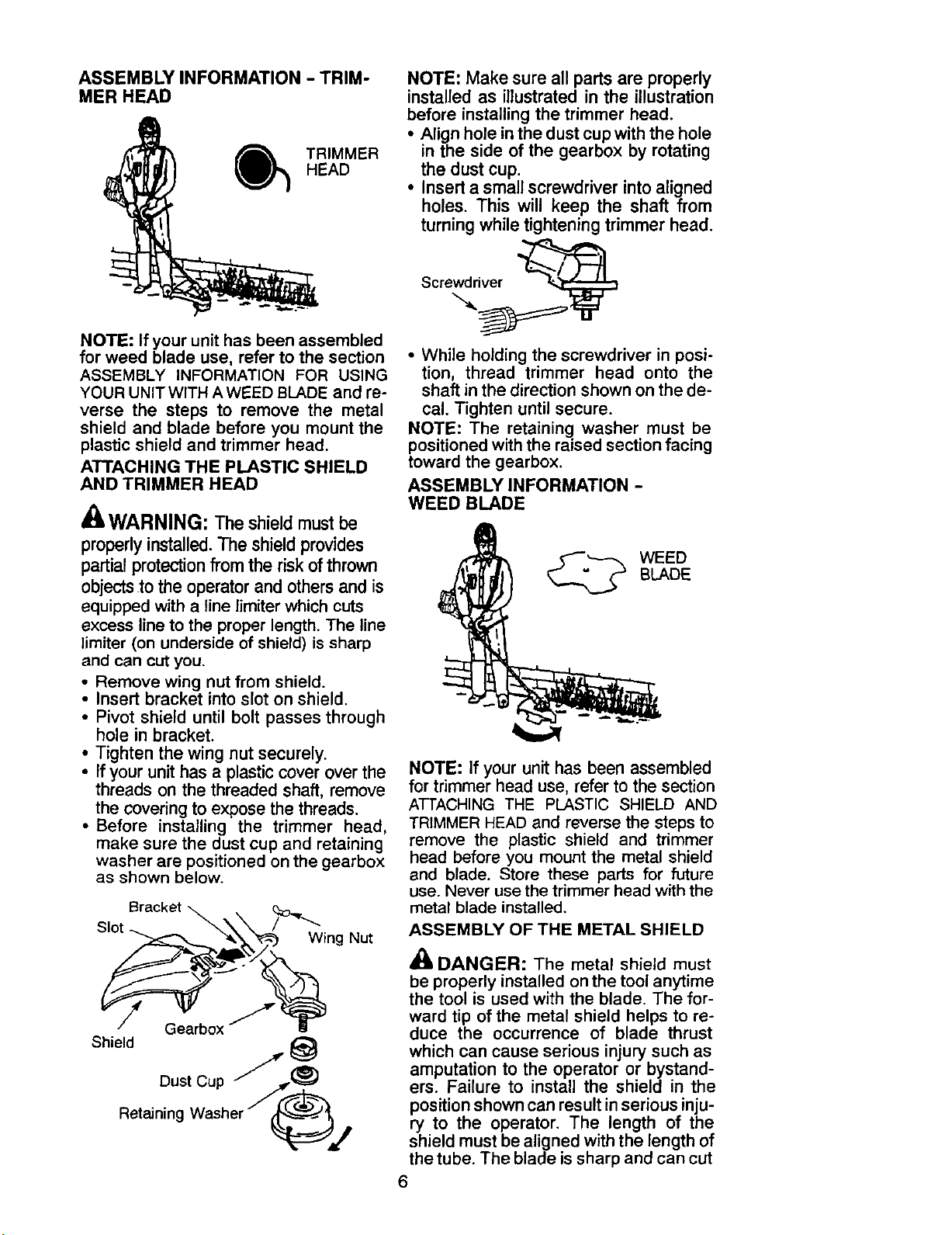
ASSEMBLY INFORMATION - TRIM-
MER HEAD
TRIMMER
HEAD
NOTE: If your unit has been assembled
for weed blade use, refer to the section
ASSEMBLY INFORMATION FOR USING
YOUR UNIT WITH A WEED BLADE and re-
verse the steps to remove the metal
shield and blade before you mount the
plastic shield and trimmer head.
ATTACHING THE PLASTIC SHIELD
AND TRIMMER HEAD
A
EL WARNING: The shield must be
properly installed.The shield provides
partial protection from the risk of thrown
objects.tothe operator and others and is
equipped with a line limiter which cuts
excess line to the proper length. The line
limiter (on underside of shield) is sharp
and can cut you.
• Remove wing nut from shield.
• Insert bracket into slot on shield.
• Pivot shield until bolt passes through
hole in bracket.
• Tighten the wing nut securely.
• If your unithas a plasticcover over the
threads on the threaded shaft, remove
the covering to expose the threads.
• Before installing the trimmer head,
make sure the dust cup and retaining
washer are positioned on the gearbox
as shown below.
Bracket _.
Slot "_..."_/_ing Nut
Shield
DustCup //J_
RetainingWasherJ(?_j
NOTE: Make sure all parts are properly
installed as illustrated in the illustration
before installing the trimmer head.
• Align hole in the dust cup with the hole
in the side of the gearbox by rotating
the dust cup.
• Insert a small screwdriver into aligned
holes. This will keep the shaft from
turning while tightening trimmer head.
Screwdriver
• While holding the screwdriver in posi-
tion, thread trimmer head onto the
shaft in the direction shown on the de-
cal. Tighten until secure.
NOTE: The retaining washer must be
positioned with the raised section facing
toward the gearbox.
ASSEMBLY INFORMATION -
WEED BLADE
WEED
BLADE
NOTE: If your unit has been assembled
for trimmer head use, refer to the section
ATTACHING THE PLASTIC SHIELD AND
TRIMMER HEAD and reverse the steps to
remove the plastic shield and trimmer
head before you mount the metal shield
and blade. Store these parts for future
use. Never use the trimmer head with the
metal blade installed.
ASSEMBLY OF THE METAL SHIELD
DANGER: The metal shield must
be properly installed onthe tool anytime
the tool is used with the blade. The for-
ward tip of the metal shield helps to re-
duce the occurrence of blade thrust
which can cause serious injury such as
amputation to the operator or bystand-
ers. Failure to install the shield in the
position shown can result inserious inju-
ry to the operator. The length of the
shield must be aligned with the length of
the tube. The blade issharp and can cut
6
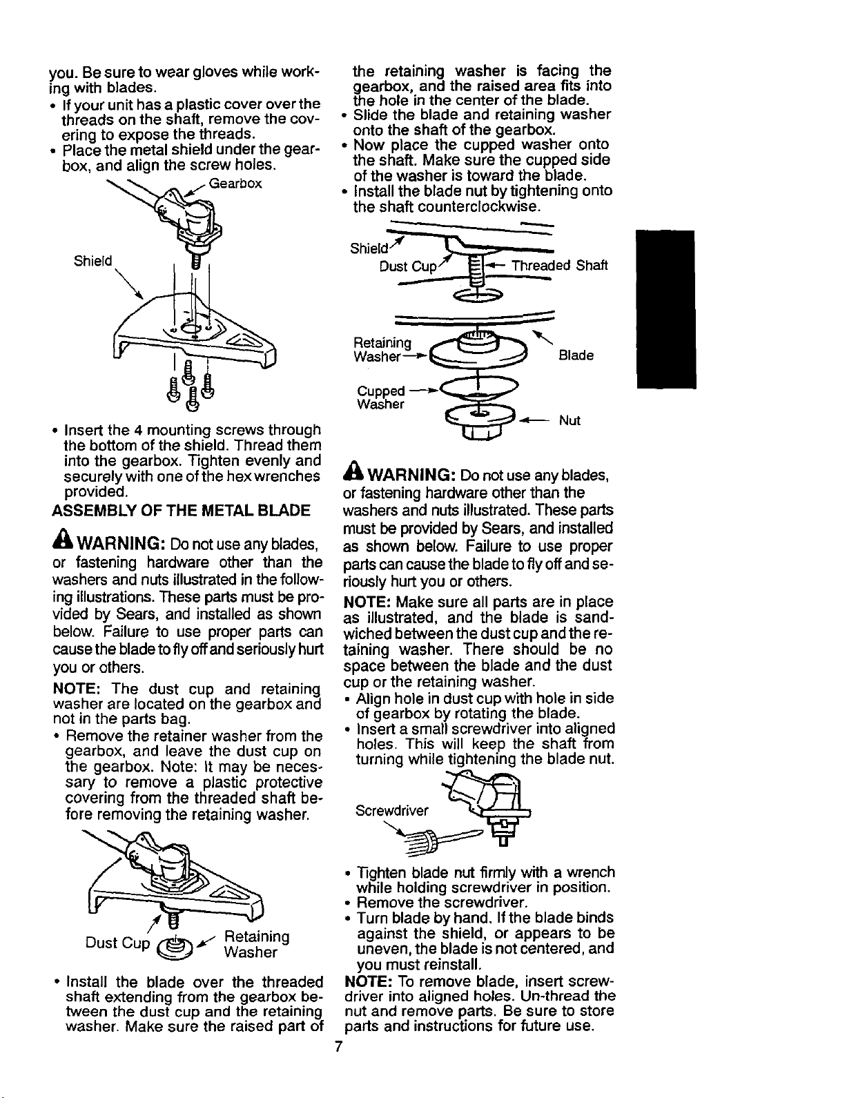
you. Be sure to wear gloves while work-
ing with blades.
• If your unit has a plastic cover over the
threads on the shaft, remove the cov-
ering to expose the threads.
• Place the metal shield under the gear-
box, and align the screw holes.
Shield
• Insert the 4 mounting screws through
the bottom of the shield. Thread them
into the gearbox. Tighten evenly and
securely with one of the hex wrenches
provided.
ASSEMBLY OF THE METAL BLADE
_(_ WARNING: Do not use any blades,
or fastening hardware other than the
washers and nuts illustrated in the follow-
ing illustrations. These parts must be pro-
vided by Sears, and installed as shown
below. Failure to use proper parts can
cause the blade to fly offand seriously hurt
you or others.
NOTE: The dust cup and retaining
washer are located on the gearbox and
not in the parts bag.
• Remove the retainer washer from the
gearbox, and leave the dust cup on
the gearbox. Note: It may be neces-
sary to remove a plastic protective
covering from the threaded shaft be-
fore removing the retaining washer.
Retaining
Dust Cup _l
Washer
• Install the blade over the threaded
shaft extending from the gearbox be-
tween the dust cup and the retaining
washer. Make sure the raised part of
the retaining washer is facing the
gearbox, and the raised area fits into
the hole in the center of the blade.
• Slide the blade and retaining washer
onto the shaft of the gearbox.
• Now place the cupped washer onto
the shaft. Make sure the cupped side
of the washer is toward the blade.
• Install the blade nut by tightening onto
the shaft counterclockwise.
Shield/_' _
Dust Cup/" _=_"_- Threaded Shaft
Retaining _
Washer--__ Blade
Cupped ---__
Washer
_1._ _ Nut
A(_WARNING: Do not use any blades,
or fastening hardware other than the
washers and nuts illustrated. These parts
must be provided by Sears, and installed
as shown below. Failure to use proper
parts can cause the blade to fly off and se-
riously hurt you or others.
NOTE: Make sure all parts are in place
as illustrated, and the blade is sand-
wiched between the dust cup and the re-
taining washer. There should be no
space between the blade and the dust
cup or the retaining washer.
• Align hole in dust cup with hole in side
of gearbox by rotating the blade.
• Insert a small screwdriver into aligned
holes. This will keep the shaft from
turning while tightening the blade nut.
Scre@_
• _ghten blade nut firmly with a wrench
while holding screwdriver in position.
• Remove the screwdriver.
• Turn blade by hand. If the blade binds
against the shield, or appears to be
uneven, the blade is not centered, and
you must reinstall.
NOTE: To remove blade, insert screw-
driver into aligned holes. Un-thread the
nut and remove parts. Be sure to store
parts and instructions for future use.
7
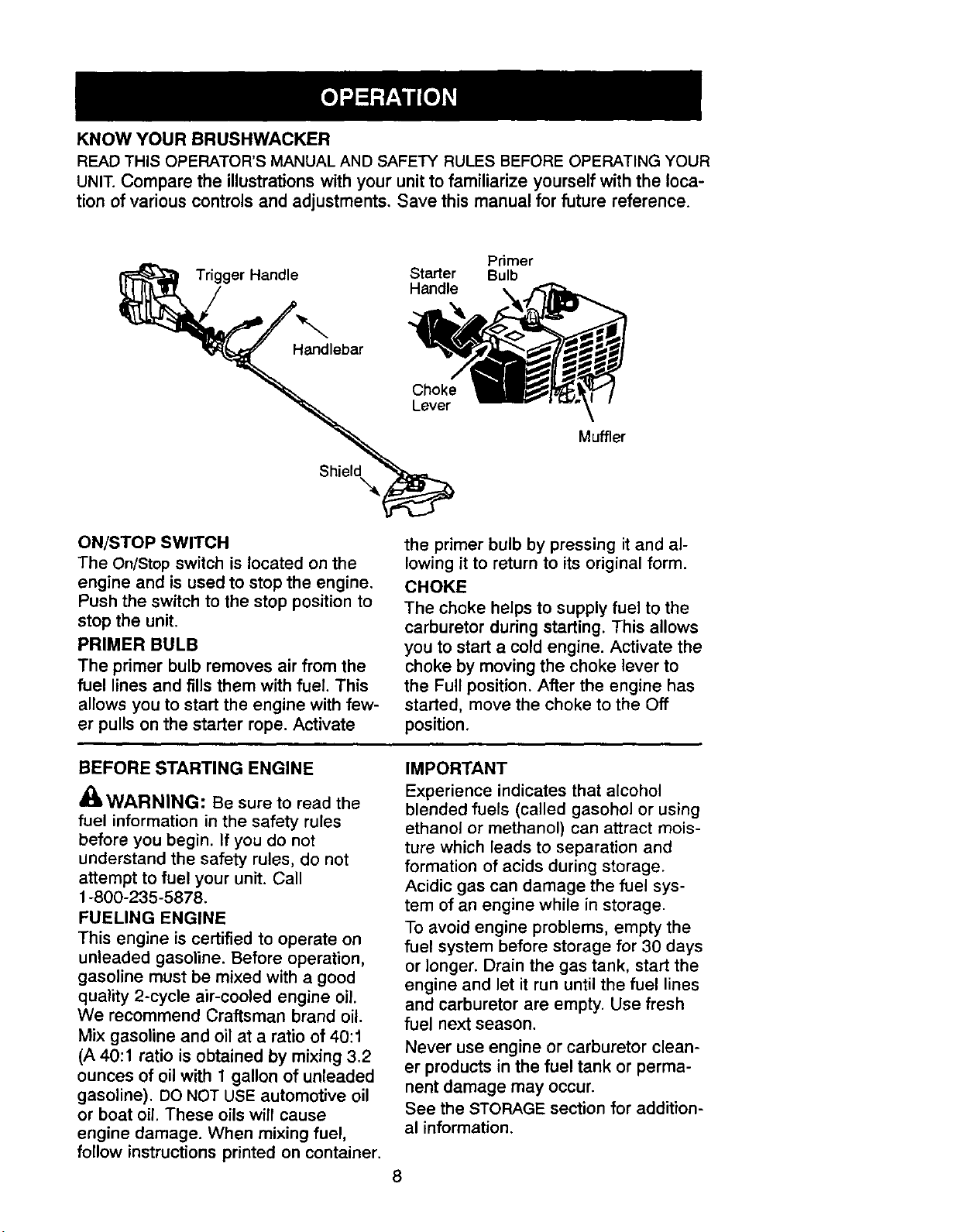
KNOWYOUR BRUSHWACKER
READTHIS OPERATOR'S MANUAL AND SAFETY RULES BEFORE OPERATING YOUR
UNIT. Compare the illustrations with your unit to familiarize yourself with the loca-
tion of various controls and adjustments. Save this manual for future reference.
Primer
Trigger Handle Starter Bulb
Handle
Handlebar
ShieldX
Muffler
ON/STOP SWITCH
The On/Stop switch is located on the
engine and is used to stop the engine.
Push the switch to the stop position to
stop the unit.
PRIMER BULB
The primer bulb removes air from the
fuel lines and fills them with fuel. This
allows you to start the engine with few-
er pulls on the starter rope. Activate
the primer bulb by pressing it and al-
lowing it to return to its original form.
CHOKE
The choke helps to supply fuel to the
carburetor during starting. This allows
you to start a cold engine. Activate the
choke by moving the choke lever to
the Full position. After the engine has
started, move the choke to the Off
position.
BEFORE STARTING ENGINE
_WARNING: Be sure to read the
fuel information in the safety rules
before you begin. If you do not
understand the safety rules, do not
attempt to fuel your unit. Call
1-800-235-5878.
FUELING ENGINE
This engine is certified to operate on
unleaded gasoline. Before operation,
gasoline must be mixed with a good
quality 2-cycle air-cooled engine oil.
We recommend Craftsman brand oil.
Mix gasoline and oil at a ratio of 40:1
(A 40:1 ratio is obtained by mixing 3.2
ounces of oil with 1 gallon of unleaded
gasoline). DO NOT USE automotive oil
or boat oil. These oils will cause
engine damage. When mixing fuel,
follow instructions printed on container.
IMPORTANT
Experience indicates that alcohol
blended fuels (called gasohol or using
ethanol or methanol) can attract mois-
ture which leads to separation and
formation of acids during storage.
Acidic gas can damage the fuel sys-
tem of an engine while in storage.
To avoid engine problems, empty the
fuel system before storage for 30 days
or longer. Drain the gas tank, start the
engine and let it run until the fuel lines
and carburetor are empty. Use fresh
fuel next season.
Never use engine or carburetor clean-
er products in the fuel tank or perma-
nent damage may occur.
See the STORAGE section for addition-
al information.
STOPPING YOUR ENGINE
• Move the ON/STOP switch to the
STOP position.
• If engine does not stop, move choke
to the FULL CHOKE position.
STARTING YOUR ENGINE
z't
dBLWARNING: The trimmer head will
turn while starting the engine. Avoid any
contact with the muffler. A hot muffler
can cause serious burns.
• Rest engine and shield on ground,
supporting trimmer head off ground.
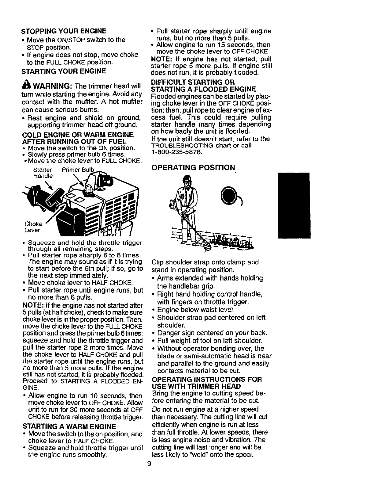
COLD ENGINE OR WARM ENGINE
AFTER RUNNING OUT OF FUEL
• Move the switch to the ON position.
• Slowly press primer bulb 6 times.
• Move the choke lever to FULLCHOKE.
Starter
Handle \
Choke
Lever
• Squeeze and hold the throttle trigger
through all remaining steps.
• Pull starter rope sharply 6 to 8 times.
The engine may sound as if it is trying
to start before the 6th pull; if so, go to
the next step immediately.
• Move choke lever to HALF CHOKE.
• Pull starter rope until engine runs, but
no more than 6 pulis.
NOTE: If the engine has not started after
5 pulls (at half choke), checkto make sure
choke lever is in the proper position. Then,
move the choke lever to the FULLCHOKE
position and press the primer bulb 6times;
squeeze and hold the throttle trigger and
pull the starter rope 2 more times. Move
the choke lever to HALF CHOKE and pull
the starter rope until the engine runs, but
no more than 5 more pulls. If the engine
still has not started, it is probably flooded.
Proceed to STARTING A FLOODED EN-
GINE.
• Allow engine to run 10 seconds, then
move choke lever to OFFCHOKE.Allow
unit to run for 30 more seconds at OFF
CHOKE before releasing throttle trigger.
STARTING A WARM ENGINE
• Move the switch tothe on position, and
choke lever to HALFCHOKE.
• Squeeze and hold throttle trigger until
the engine runs smoothly.
• Pull starter rope sharply until engine
runs, but no more than 5 pulls.
• Allow engine to run 15 seconds, then
move the choke lever to OFF CHOKE
NOTE: If engine has not started, pull
starter rope 5 more pulls. If engine still
does not run, it is probably flooded.
DIFFICULT STARTING OR
STARTING A FLOODED ENGINE
Flooded engines can be started by plac-
ing choke lever in the OFF CHOKE posi-
tion; then, pull ropeto clear engine of ex-
cess fuel. This could require pulling
starter handle many times depending
on how badly the unit is flooded.
Ifthe unit still doesn't start, refer to the
"TROUBLESHOOTINGchart or call
1-800-235-5878.
OPERATING POSITION
Clip shoulder strap onto clamp and
stand in operating position.
• Arms extended with hands holding
the handlebar grip.
• Right hand holding control handle,
with fingers on throttle trigger.
• Engine below waist level.
• Shoulder strap pad centered on left
shoulder.
• Danger sign centered on your back.
• Full weight of tool on left shoulder.
• Without operator bending over, the
blade or semi-automatic head is near
and parallel to the ground and easily
contacts material to be cut.
OPERATING INSTRUCTIONS FOR
USE WITH TRIMMER HEAD
Bring the engine to cutting speed be-
fore entering the material to be cut.
Do not run engine at a higher speed
than necessary. The cutting line will cut
efficiently when engine is run at less
than full throttle. At lower speeds, there
is less engine noise and vibration. The
cutting line will last longer and will be
less likely to '_veld" onto the spool.
9
If the trimmer head does not turn when
the engine is in operation, make sure
the drive shaft housing is properly
seated in engine shroud.
Always release the throttle trigger and
allow the engine to return to idle speed
when not cutting.
To stop engine:
• Release the throttle trigger.
• Move the ON/STOP switch to the
STOP position.
• If engine does not stop, move choke
to the FULLCHOKE position.
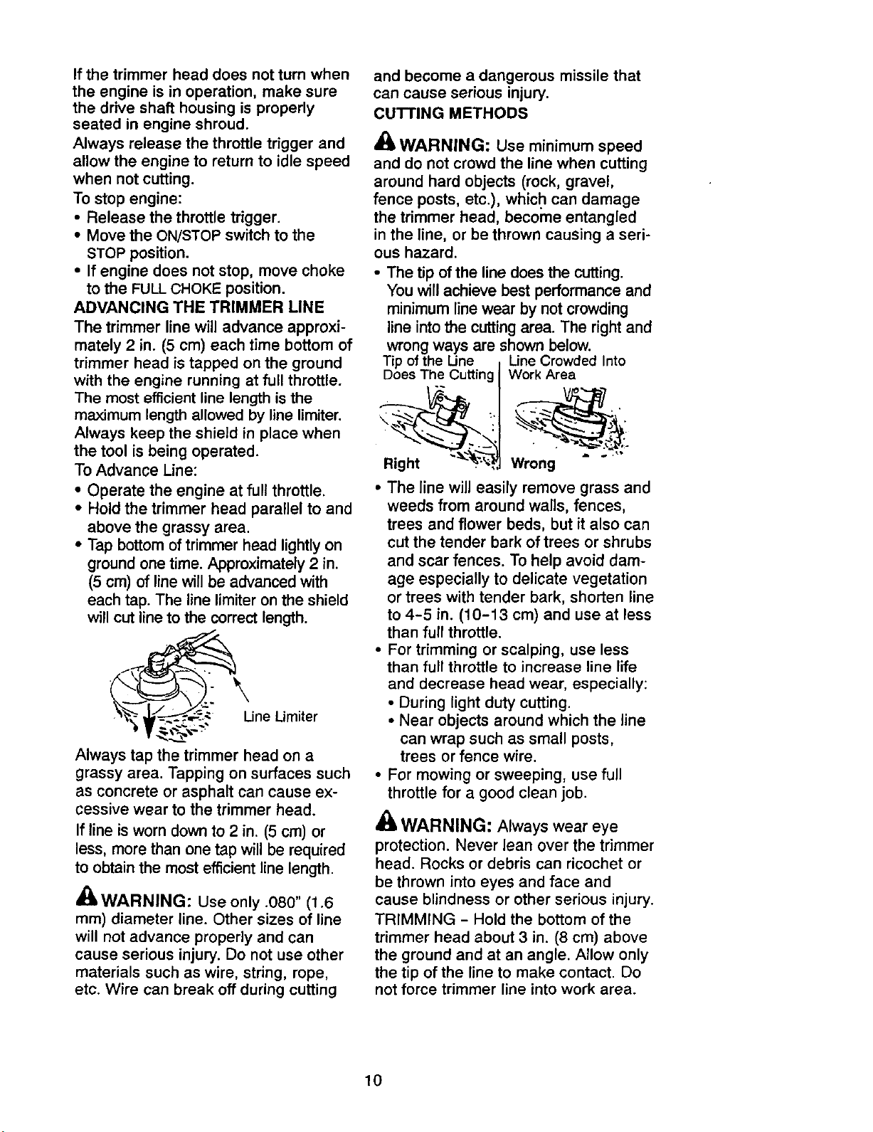
ADVANCING THE TRIMMER LINE
The trimmer line will advance approxi-
mately 2 in. (5 cm) each time bottom of
trimmer head is tapped on the ground
with the engine running at full throttle.
The most efficientline length is the
maximum length allowed by line limiter.
Always keep the shield in place when
the tool is being operated.
To Advance Line:
• Operate the engine at full throttle.
• Hold the trimmer head parallel to and
above the grassy area.
• Tap bottom of trimmer head lightly on
ground one time. Approximately 2 in.
(5 cm) of line will be advanced with
each tap. The line limiter on the shield
will cut line to the correct length.
• /_.
he_v_-_-_,_'- _ Limiter
Always tap the trimmer head on a
grassy area. Tapping on surfaces such
as concrete or asphalt can cause ex-
cessive wear to the trimmer head.
If line is worn down to 2 in. (5 cm) or
less, more than one tap will be required
to obtain the most efficient line length.
_ WARNING: Use only .080" (1.6
mm) diameter line. Other sizes of line
will not advance properly and can
cause serious injury. Do not use other
materials such as wire, string, rope,
etc. Wire can break off during cutting
and become a dangerous missile that
can cause serious injury.
cu'rrlNG METHODS
WARNING: Use minimum speed
and do not crowd the line when cutting
around hard objects (rock, gravel,
fence posts, etc.), which can damage
the trimmer head, becorne entangled
in the line, or be thrown causing a seri-
ous hazard.
• The tip of the line does the cutting.
You will achieve best performance and
minimum line wear by not crowding
line into the cutting area. The right and
wrong ways are shown below.
Tip of the Une LineCrowded Into
Does The Cutting
Right __
Work Area
• . _._o
Wrong
• The line will easily remove grass and
weeds from around walls, fences,
trees and flower beds, but it also can
cut the tender bark of trees or shrubs
and scar fences. To help avoid dam-
age especially to delicate vegetation
or trees with tender bark, shorten line
to 4-5 in. (10-13 cm) and use at less
than full throttle.
• For trimming or scalping, use less
than full throttle to increase line life
and decrease head wear, especially:
• During light duty cutting.
• Near objects around which the line
can wrap such as small posts,
trees or fence wire.
• For mowing or sweeping, use full
throttle for a good clean job.
WARNING: Always wear eye
protection. Never lean over the trimmer
head. Rocks or debris can ricochet or
be thrown into eyes and face and
cause blindness or other serious injury.
TRIMMING - Hold the bottom of the
trimmer head about 3 in. (8 cm) above
the ground and at an angle. Allow only
the tip of the line to make contact• Do
not force trimmer line into work area.
10
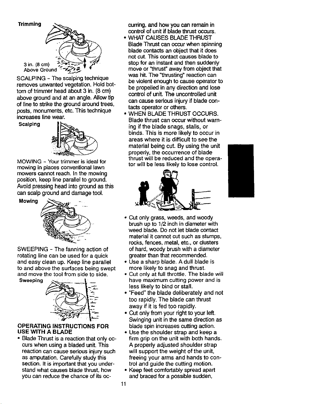
SCALPING - The scalping technique
removes unwanted vegetation. Hold bot-
tom of trimmer head about 3 in. (8 cm)
above ground and at an angle. Allow tip
of line to strike the ground around trees,
posts, monuments, etc. This technique
increases line wear.
Scalping
MOWING - Your trimmer is ideal for
mowing in places conventional lawn
mowers cannot reach. In the mowing
position, keep line parallel to ground.
Avoid pressing head into ground as this
can scalp ground and damage tool.
Mowing
SWEEPING - The fanning action of
rotating line can be used for a quick
and easy clean up. Keep line parallel
to and above the surfaces being swept
and move the tool from side to side.
Sweeping __,.._..,
OPERATING INSTRUCTIONS FOR
USE WITH A BLADE
• Blade Thrust is a reaction that only oc-
curs when using a bladed unit. This
reaction can cause serious injury such
as amputation. Carefully study this
section. It is important that you under-
stand what causes blade thrust, how
you can reduce the chance of its oc-
curring,and how you can remain in
control of unit ifblade thrust occurs.
• WHAT CAUSES BLADE THRUST
Blade Thrust can occurwhen spinning
blade contactsan object that it does
not cut. This contactcauses blade to
stopfor an instant and then suddenly
move or "thrust" away from object that
was hit.The '_hrusting" reaction can
be violent enough to cause operator to
be propelled in any direction and lose
controlof unit. The uncontrolledunit
can cause serious injury if blade con-
tacts operator or others.
• WHEN BLADE THRUST OCCURS.
Blade thrust can occur without warn-
ing if the blade snags, stalls, or
binds. This is more likely to occur in
areas where it is difficult to see the
material being cut. By using the unit
properly, the occurrence of blade
thrust will be reduced and the opera-
tor will be less likely to lose control.
11
• Cut only grass, weeds, and woody
brush up to 1/2 inch in diameter with
weed blade. Do not let blade contact
material it cannot cut such as stumps,
rocks, fences, metal, etc., or clusters
of hard, woody brush with a diameter
greater than that recommended.
• Use a sharp blade. A dull blade is
more likely to snag and thrust.
• Cut only at full throttle. The blade will
have maximum cutting power and is
less likely to bind or stall.
• "Feed" the blade deliberately and not
too rapidly. The blade can thrust
away if it is fed too rapidly.
• CUt only from your right to your left.
Swinging unit in the same direction as
blade spin increases cutting action.
• Use the shoulder strap and keep a
firm grip on the unit with both hands.
A properly adjusted shoulder strap
will support the weight of the unit,
freeing your arms and hands to con-
trol and guide the cutting motion.
Keep feet comfortably spread apart
and braced for a possible sudden,
rapid thrustof unit. Do not overreach.
Keep firm footing and balance.
• Keep blade below waist level. Itwill
be easier to maintain control of unit.
• Do not raise the engine above your
waist as the blade can come danger-
ously close to your body.
• Do not swing the unit with such force
that you are in danger of losing your
balance.
Bring the engine to cutting speed be-
fore entering the material to be cut.
Ifthe blade does not turn when you
squeeze the throttle trigger, make sure
the tube is fully inserted into engine.
Always release the throttle trigger and
allow engine to return to idle speed
when not cutting. The blade should not
turn while the engine is running at idle.
If the blade turns at idle, do not use
your unit. Refer to the Carburetor ad-
justment section or contact your Sears
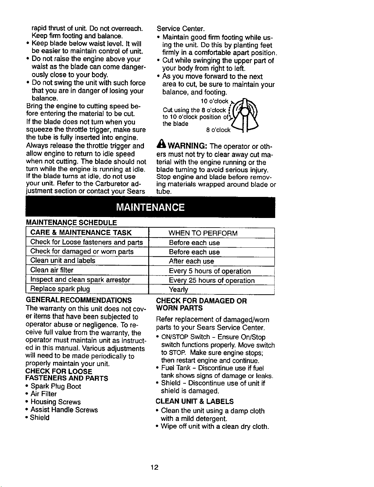
MAINTENANCE SCHEDULE
Service Center.
• Maintain good firm footing while us-
ing the unit. Do this by planting feet
firmly in a comfortable apart position.
• Cut while swinging the upper part of
your body from right to left.
• As you move forward to the next
area to cut, be sure to maintain your
balance, and footing.
10 o'clock _/_
Cut using the 8 o clock ={ i_r_}
to lO o clock position of_,y _'1 _'
the blade • I I
8 o'clock _
WARNING: The operator or oth-
ers must not try to clear away cut ma-
terial with the engine running or the
blade turning to avoid serious injury.
Stop engine and blade before remov-
ing materials wrapped around blade or
tube.
CARE & MAINTENANCE TASK
Check for Loose fasteners and parts
Check for damaged or worn parts
Clean unit and labels
Clean air filter
Inspect and clean spark arrestor
Replace spark plug
GENERALRECOMMENDATIONS
The warranty on this unit does not cov-
er items that have been subjected to
operator abuse or negligence. To re-
ceive full value from the warranty, the
operator must maintain unit as instruct-
ed in this manual. Various adjustments
will need to be made periodically to
WHEN TO PERFORM
Before each use
Before each use
After each use
Every 5 hours of operation
Every 25 hours of operation
Yearly
CHECK FOR DAMAGED OR
WORN PARTS
Refer replacement of damaged/worn
parts to your Sears Service Center.
• ON/STOPSwitch - Ensure On/Stop
switch functions properly. Move switch
to STOP. Make sure engine stops;
then restart engine and continue.
properly maintain your unit.
CHECK FOR LOOSE
FASTENERS AND PARTS
• Spark Plug Boot
• Air Filter
• Housing Screws
• Assist Handle Screws
• Shield
• Fuel Tank - Discontinue use if fuel
tank shows signs of damage or leaks.
• Shield - Discontinue use of unit if
shield is damaged.
CLEAN UNIT & LABELS
• Clean the unit using a damp cloth
with a mild detergent.
• Wipe off unit with a clean dry cloth.
12
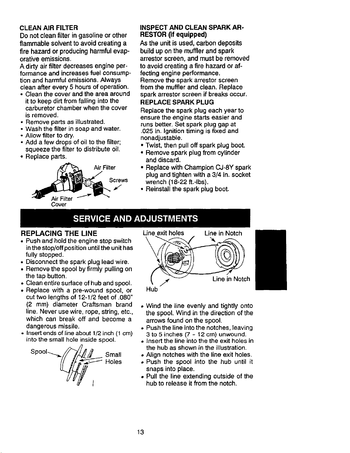
CLEANAIR FILTER
Donot clean filter in gasoline or other
flammable solvent to avoid creating a
fire hazard or producing harmful evap-
orative emissions.
A dirty air filter decreases engine per-
formance and increases fuel consump-
tion and harmful emissions. Always
clean after every 5 hours of operation.
• Clean the cover and the area around
it to keep dirt from falling into the
carburetor chamber when the cover
is removed.
• Remove parts as illustrated.
• Wash the filter in soap and water.
• Allow filter to dry.
• Add a few drops of oil to the filter;
squeeze the filter to distribute oil.
• Replace parts.
Filter
Screws
f
Cover
INSPECT AND CLEAN SPARK AR-
RESTOR (if equipped)
As the unit is used, carbon deposits
build up on the muffler and spark
arrestor screen, and must be removed
to avoid creating a fire hazard or af-
fecting engine performance.
Remove the spark arrestor screen
from the muffler and clean. Replace
spark arrestor screen if breaks occur.
REPLACE SPARK PLUG
Replace the spark plug each year to
ensure the engine starts easier and
runs better. Set spark plug gap at
.025 in. Ignition timing is fixed and
nonadjustable.
• Twist, then pull off spark plug boot.
• Remove spark plug from cylinder
and discard.
• Replace with Champion CJ-BY spark
plug and tighten with a 3/4 in. socket
wrench (18-22 ft.-Ibs).
• Reinstall the spark plug boot.
REPLACING THE LINE
• Push and hold the engine stop switch
in the stop/off position until the unit has
fully stopped.
• Disconnect the spark plug lead wire.
• Remove the spool by firmly pulling on
the tap button.
• Clean entire surface of hub and spool.
• Replace with a pre-wound spool, or
cut two lengths of 12-1/2 feet of .080"
(2 mm) diameter Craftsman brand
line. Never use wire, rope, string, etc.,
which can break off and become a
dangerous missile.
• Insert ends of line about 1/2 inch (1 cm)
into the small hole inside spool.
P
• Holes
I
Line exit holes Line in Notch
__, ._ _ U}n, in Notch
Hub
• Wind the line evenly and tightly onto
the spool. Wind in the direction of the
arrows found on the spool.
• Push the line into the notches, leaving
3 to 5 inches (7 - 12 cm) unwound.
• Insert the line into the the exit holes in
the hub as shown in the illustration.
• Align notches with the line exit holes.
• Push the spool into the hub until it
snaps into place.
• Pull the line extending outside of the
hub to release it from the notch.
13
CARBURETOR ADJUSTMENT
_IL WARNING: The trimmer head or
blade will be spinning during most of this
procedure. Wear protective equipment
and observe all safety precautions. After
making mixture adjustments, recheck
idle speed.
Carburetor adjustment is critical and if
done improperly can permanently
damage the engine as well as the car-
buretor. If you require further assis-
tance or are unsure about performing
this procedure, call our customer as-
sistance help line at 1-800-235-5878.
Old fuel, a dirty air filter, a dirty fuel fil-
ter, or flooding may give the impres-
sion of an improperly adjusted carbu-
retor. Check these conditions before
adjusting the carburetor.
The carburetor has been carefully set
at the factory. Adjustments may be
necessary if you notice any of the fol-
lowing conditions:
• Engine will not idle. See IDLE SPEED
under adjusting procedure.
• Engine dies or hesitates instead of
accelerating. See ACCELERATION
CHECK under adjusting procedure.
• Loss of cutting power. See MIXTURE
ADJUSTMENT under adjusting
procedure.
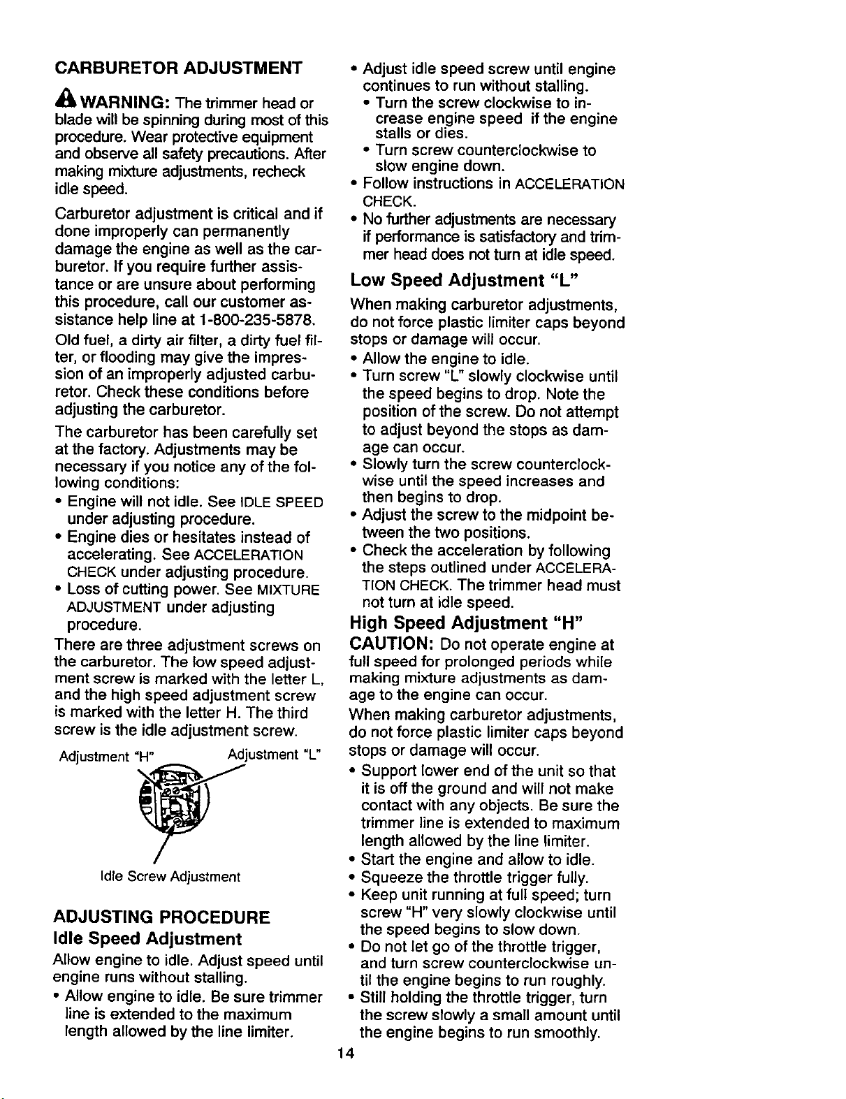
There are three adjustment screws on
the carburetor. The low speed adjust-
ment screw is marked with the letter L,
and the high speed adjustment screw
is marked with the letter H. The third
screw is the idle adjustment screw.
Adjustment "H"
Adjustment "L"
Idle Screw Adjustment
ADJUSTING PROCEDURE
Idle Speed Adjustment
Allow engine to idle. Adjust speed until
engine runs without stalling.
• Allow engine to idle. Be sure trimmer
line is extended to the maximum
length allowed by the line limiter.
• Adjust idle speed screw until engine
continues to run without stalling.
• Turn the screw clockwise to in-
crease engine speed if the engine
stalls or dies.
• Turn screw counterclockwise to
slow engine down.
• Follow instructions in ACCELERATION
CHECK.
• No further adjustments are necessary
if performance is satisfactory and trim-
mer head does not turn at idle speed.
Low Speed Adjustment "L"
When making carburetor adjustments,
do not force plastic limiter caps beyond
stops or damage will occur.
• Allow the engine to idle.
• Turn screw "L" slowly clockwise until
the speed begins to drop. Note the
position of the screw. Do not attempt
to adjust beyond the stops as dam-
age can occur.
• Slowly turn the screw counterclock-
wise until the speed increases and
then begins to drop.
• Adjust the screw to the midpoint be-
tween the two positions.
• Check the acceleration by following
the steps outlined under ACCELERA-
TION CHECK. The trimmer head must
not turn at idle speed.
High Speed Adjustment "H"
CAUTION: Do not operate engine at
full speed for prolonged periods while
making mixture adjustments as dam-
age to the engine can occur.
When making carburetor adjustments,
do not force plastic limiter caps beyond
stops or damage will occur.
• Support lower end of the unit so that
it is off the ground and will not make
contact with any objects. Be sure the
trimmer line is extended to maximum
length allowed by the line limiter.
• Start the engine and allow to idle.
• Squeeze the throttle trigger fully.
• Keep unit running at full speed; turn
screw "H" very slowly clockwise until
the speed begins to slow down.
• Do not let go of the throttle trigger,
and turn screw counterclockwise un-
til the engine begins to run roughly.
• Still holding the throttle trigger, turn
the screw slowly a small amount until
the engine begins to run smoothly.
14
Acceleration Check
• Allow engine to idle. Be sure trimmer
line is extended to the maximum
length allowed by the line limiter.
• Squeeze trigger fully: If the engine
does not accelerate smoothly, turn
screw "L" counterclockwise a small
amount (no more than the width of
the slot in the adjusting screw). Do
not attempt to adjust screws beyond
the stops as damage can occur.
• Repeat above steps until smooth ac-
celeration is obtained. Do not at-
tempt to adjust the screw beyond the
stops as damage can occur.
IGNITION TIMING
Ignition timing is fixed,non-adjustable.
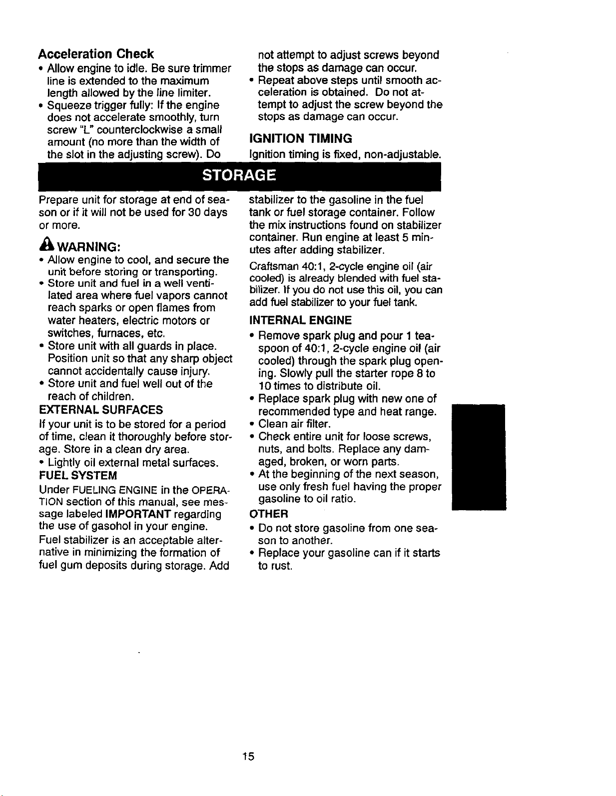
Prepare unit for storage at end of sea-
son or if it will not be used for 30 days
or more.
_WARNING:
• Allow engine to cool, and secure the
unit before storing or transporting.
• Store unit and fuel in a well venti-
lated area where fuel vapors cannot
reach sparks or open flames from
water heaters, electric motors or
switches, furnaces, etc.
• Store unit with all guards in place.
Position unit so that any sharp object
cannot accidentally cause injury.
• Store unit and fuel well out of the
reach of children.
EXTERNAL SURFACES
if your unit is to be stored for a period
of time, clean it thoroughly before stor-
age. Store in a clean dry area.
• Lightly oil external metal surfaces.
FUEL SYSTEM
Under FUELING ENGINE in the OPERA-
TION section of this manual, see mes-
sage labeled IMPORTANT regarding
the use of gasohol in your engine.
Fuel stabilizer is an acceptable alter-
native in minimizing the formation of
fuel gum deposits during storage. Add
stabilizer to the gasoline in the fuel
tank or fuel storage container. Follow
the mix instructions found on stabilizer
container. Run engine at least 5 min-
utes after adding stabilizer.
Craftsman 40:1, 2-cycle engine oil (air
cooled) is already blended with fuel sta-
bilizer. If you do not use this oil, you can
add fuel stabilizer to your fuel tank.
INTERNAL ENGINE
• Remove spark plug and pour 1 tea-
spoon of 40:1, 2-cycle engine oil (air
cooled) through the spark plug open-
ing. Slowly pull the starter rope 8 to
10 times to distribute oil.
• Replace spark plug with new one of
recommended type and heat range.
• Clean air filter.
• Check entire unit for loose screws,
nuts, and bolts. Replace any dam-
aged, broken, or worn parts.
• At the beginning of the next season,
use only fresh fuel having the proper
gasoline to oil ratio.
OTHER
• Do not store gasoline from one sea-
son to another.
• Replace your gasoline can if it starts
to rust.
15
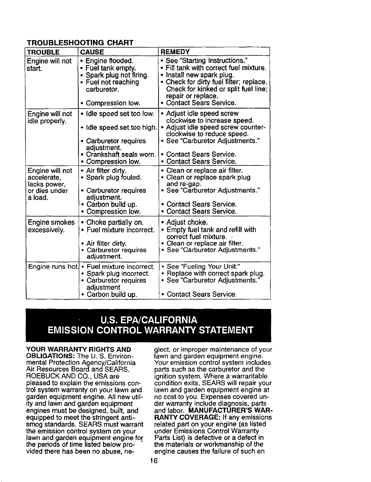
TROUBLESHOOTING CHART
TROUBLE
Engine will not
start.
Engine will not
idle properly.
Engine will not
accelerate,
lacks power,
or dies under
a load.
Engine smokes
excessively.
Engine runs hot.
CAUSE
• Engine flooded.
Fuel tank empty.
Spark plug not firing,
• Fuel not reaching
carburetor.
• Compression low.
• Idle speed set too low.
• Idle speed set too high.
• Carburetor requires
adjustment.
• Crankshaft seals worn.
• Compression low.
• Air filter dirty.
• Spark plug fouled.
• Carburetor requires
adjustment.
• Carbon build up.
• Compression low.
• Choke partially on.
• Fuel mixtureincorrect.
• Air filter dirty.
• Carburetor requires
adjustment.
• Fuel mixture incorrect.
• Spark plug incorrect.
• Carburetor requires
adjustment
• Carbon build up.
YOUR WARRANTYRIGHTS AND
REMEDY
• See "Starting Instructions."
• Fill tank with correct fuel mixture.
Install new spark plug.
: Check for dirty fuel filter; replace.
Check for kinked or split fuel line;
repair or replace.
• Contact Sears Service.
• Adjust idle speed screw
clockwise to increase speed.
• Adjust idle speed screw counter-
clockwise to reduce speed.
• See "Carburetor Adjustments."
• Contact Sears Service.
• Contact Sears Service.
• Clean or replace air filter.
• Clean or replace spark plug
and re-gap.
• See "Carburetor Adjustments."
• Contact Sears Service.
• Contact Sears Service.
• Adjust choke.
• Empty fuel tank and refill with
correct fuel mixture. -
• Clean or replace air filter.
I" See "Carburetor Adjustments."
I" See "Fueling Your Unit."
• Replace with correct spark plug.
• See "Carburetor Adjustments."
_• Contact Sears Service.
OBLIGATIONS: The U. S. Environ-
mental Protection Agency/California
Air Resources Board and SEARS,
ROEBUCK AND CO., USA are
pleased to explain the emissions con-
trol system warranty on your lawn and
garden equipment engine. All new util-
ity and lawn and garden equipment
engines must be designed, built, and
equipped to meet the stringent anti-
smog standards. SEARS must warrant
the emission control system on y.our
lawn and garden equipment engine fo.r
the periods of time listed below pro-
vided there has been no abuse, ne-
glect, or improper maintenance of your
lawn and garden equipment engine.
Your emission control system includes
parts such as the carburetor and the
ignition system. Where a warrantable
condition exits, SEARS will repair your
lawn and garden equipment engine at
no cost to you. Expenses covered un-
der warranty include diagnosis, parts
and labor. MANUFACTURER'S WAR-
RANTY COVERAGE: If any emissions
related part on your engine (as listed
under Emissions Control Warranty
Parts List) is defective or a defect in
the materials or workmanship of the
engine causes the failure of such an
16
emission related part, the part will be
repaired or replaced by SEARS.
OWNER'S WARRANTY RESPONSl-
BILrrlES: As the lawn and garden
equipment engine owner, you are re-
sponsible for the performance of the
required maintenance listed in your
Owner's Manual. SEARS recommends
that you retain all receipts covering
maintenance on your lawn and garden
equipment engine, but SEARS cannot
deny warranty solely for the lack of re-
ceipts or for your failure to ensure the
performance of all scheduled mainte-
nance. As the lawn and garden
equipment engine owner, you should
be aware that SEARS may deny you
warranty coverage if your lawn and
garden equipment engine or a part of it
has failed due to abuse, neglect, im-
proper maintenance, unapproved
modifications, or the use of parts not
made or approved by the original
equipment manufacturer. You are re-
sponsible for presenting your lawn and
garden equipment engine to a SEARS
authorized repair center as soon as a
problem exists. Warranty repairs
should be completed in a reasonable
amount of time, not to exceed 30 days.
If you have any questions regarding
your warranty rights and responsibili-
ties, you should contact your nearest
authorized service center or call
SEARS at 1-800-473-7247 WARRAN-
TY COMMENCEMENT DATE: The
warranty period begins on the date the
lawn and garden equipment engine is
purchased. LENGTH OF COVER-
AGE: This warranty shall be for a peri-
od of two years from the initial date of
purchase. WHAT IS COVERED: RE-
PAIR OR REPLACEMENT OF
PARTS. Repair or replacement of any
warranted part will be performed at no
charge to the owner at an approved
SEARS servicing center. If you have
any questions regarding your warranty
rights and responsibilities, you should
contact your nearest authorized ser-
vice center or call SEARS at
1-800-473-7247. WARRANTY PE-
RIOD: Any warranted part which is not
scheduled for replacement as required
maintenance, or which is scheduled
on!y for regular inspection to the effect
of repair or replace as necessary"
shall be warranted for 2 years. Any
warranted part which is scheduled for
replacement as required maintenance
shall be warranted for the period of
time up to the first scheduled replace-
ment point for that part. DIAGNOSIS:
The owner shall not be charged for
diagnostic labor which leads to the de-
termination that a warranted part is de-
fective if the diagnostic work is per-
formed at an approved SEARS
servicing center. CONSEQUENTIAL
DAMAGES: SEARS may be liable for
damages to other engine components
caused by the failure of a warranted
part still under warranty. WHAT IS
NOT COVERED: All failures caused
by abuse, neglect, or improper mainte-
nance are not covered. ADD-ON OR
MODIFIED PARTS: The use of add-on
or modified parts can be grounds for dis-
allowing a warranty claim. SEARS is not
liable to cover failures of warranted
parts caused by the use of add-on or
modified parts. HOW TO FILE A
CLAIM: If you have any questions re-
garding your warranty rights and re-
sponsibilities, you should contact your
nearest authorized service center or
call SEARS at 1-800-473-7247.
WHERE TO GET WARRANTY SER-
VICE: Warranty services or repairsshall
be provided at all SEARS service cen-
ters. call: 1-800-473-7247. MAINTE-
NANCE, REPLACEMENT AND RE-
PAIR OF EMISSION RELATED
PARTS: Any SEARS approved re-
placement part used in the perfor-
mance of any warranty maintenance
or repair on emission related parts will
be provided without charge to the own-
er if the part is under warranty. EMIS-
SION CONTROL WARRANTY
PARTS LIST: Carburetor, ignition Sys-
tem: Spark Plug (covered up to main-
tenance schedule), ignition Module.
MAINTENANCE STATEMENT: The
owner is responsible for the perfor-
mance of all required maintenance as
defined in the owner's manual.
17
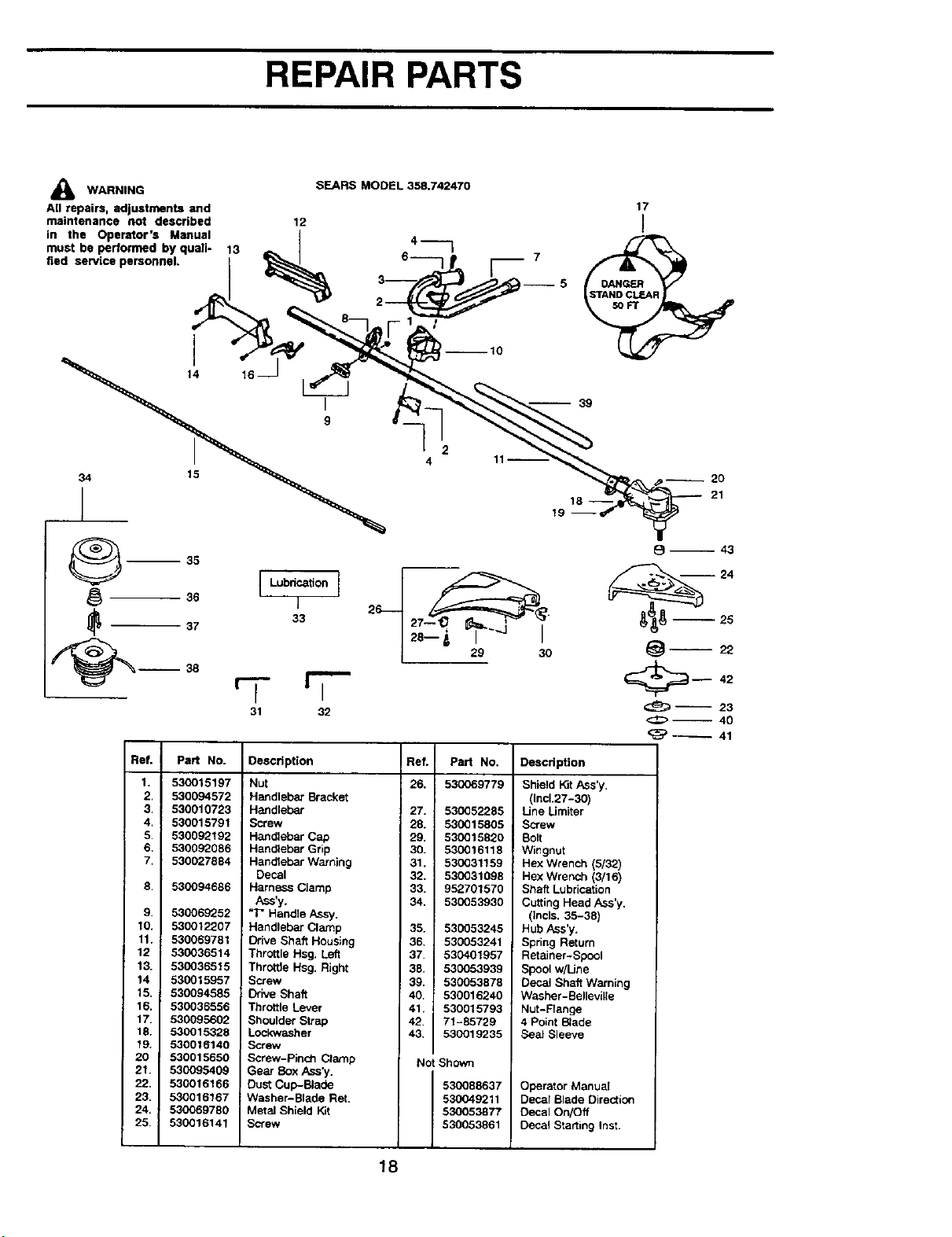
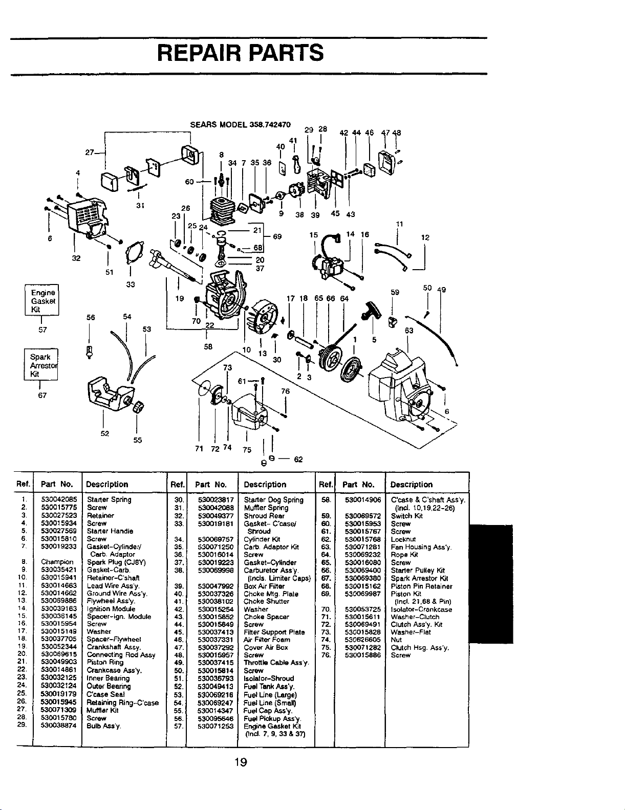
REPAIR PARTS
_lJ WARNING
All repairs, adjustments and
maintenance not described
in the Operator's Manual
must be performed by quali-
fied service personnel.
I
14
SEARS MODEL 358.742470
17
12 I
)q6
--10
16
I
39
34
/
15
[ Lubdca_on ]
1
33
31 32
2
4
18--
19
20
21
Ref.
1.
2.
3.
4,
5.
6.
7,
6.
9.
10.
11.
12
13.
14
15.
16.
17.
18.
19.
20
21.
22.
23.
24.
25.
Pad No.
530015197
530094572
530010723
530015791
530092192
530092086
530027884
530094686
530069252
530012207
530069781
530036514
530036515
530015957
530094585
530036556
530095602
530015328
530016140
530015650
530095409
530016166
530016167
530069780
530016141
Description
Nut
Handlebar Bracket
Handlebar
Screw
Handlebar Cap
Handlebar Grip
Handlebar Warning
Decal
Harness Clamp
A_s'y.
"T_ Handle Assy.
Handlebar Clamp
Drive Shaft Housing
Throttle Hsg. Left
Throttle Hsg. Right
Screw
Drive Shaft
Throttle Lever
Shoulder Strap
Lockwasher
Screw
Screw-Pinch Clamp
Gear Box Ass_/.
Duet Cup-Bade
Washer-Blade Ret.
Metal Shield Kit
Screw
Ref. Pad No.
26. 530069779
27. 530052285
28. 530015805 ,
29. 530015820 1
30. 530016118
31. 530031159
32. 530031098
33. 952701570
34. 530053930
35. 530053245
36. 530053241
37. 530401957
38. 530053939
39. 530053878
40. 530016240
41. 530015793
42. 71-85729
43. 530019235
Not Shown
DeSCription
Shield Kit Ass'y.
(Incl.27-30)
Line LJmiter
Screw
Bolt
Wingnut
Hex Wrench (5/32)
Hex Wrench (3/16)
Shaft Lubrication
Cutting Head A.s.s'y.
(Incls. 35-38)
Hub Ass'y.
Spring Return
Retainer-Spool
Spool w/Line
Decal Shaft Warning
Washer-Belleville
Nut-Flange
4 Point Blade
Seal Sleeve
Operator Manual
Decal Blade Direction
Decal On/Off
Decal Starting Inst.
530088637
530049211
530053877
530053861
_-- 23
<::¢_-- 40
18
REPAIR PARTS
57
67
ReL
t,
2.
3.
4.
5.
6.
7
6.
9.
10.
11.
12.
13
14
15.
t6.
17,
18.
19.
20.
21.
22.
23,
24.
25.
26,
27.
28.
29.
32
I
51
Part No.
530042085
530015775
530027523
530015934
530027569
530015810
530019233
Champion
530035421
630015941
530014663
530014662
530069886
530039163
530036145
530015954
530015149
530037705
53OO52344
530069615
530049903
530014861
530032125
530032124
530019179
530015945
5-30071309
530015780
630038874
i
31
J
33
SEARS MODEL 358.742470
1 4t
40
8 I
34 7 35 36
60
-- 20
37
2928 1718
9
38 39 45 43
11
t ,2
17 18 65 66 64
52
71 72 74
Description Ref. Part No.
Starter Spring 30, 530023817
Screw 31. 530042088
! Retainer 32. 530049377
Screw 33. 530019181
Starter Handle
Screw 34. 530069757
Gasket-Cyfinder/ 35. 530071250
Carb. Adaptor 36. 530016014
! Spark Plug (CJ8Y) 37, 530019223
, Gasket-Carb. 3g. 530069996
Ret ainer-C'shaft
Lead Wire Ass'y. 39. 530047992
Ground Wire Ass'y. 40 530037326
Flywheel Ass'y. 41. 5_0038102
Ignition Module 42. 530015254
Spacer-lgn. Module 43, 530015852
Screw 44 530015849
Washer 45. 530037413
Spacer-Flywheel 46, 530037331
' Crankshaft A.ssy. 47. 530037292
Connecting Rod _ssy 48. 530015957
Piston Ring 49. 530037415
Crankcase ,&._s'y. 50. 530015814
Inner Beanng 51, 530036793
Outer Beanng 52. 530049413
C'case Sea] 53. 530069216
Retaining Riog-C'case 54. 530069247
Muffler Kit 55. I 530014347
Screw 56. 530095646
Bulb A.ss'y. 57. 530071253
Description
Ref, Pa_ No.
Stader Dog Spring 58. 530014906
Muffler Spring
Shroud Rear 59. 530069572
Gasket- C'case/ 60. 530015953
Shroud 61. 530015767
Cyitnder Kit 62. 530015768
Carb Adaptor Kit 63. 550071281
Screw 64. 530069232
Gasket-Cylinder 65. 530016080
Carburetor Ass'y, 66. 530069400
{Inds. Limiter Caps} 67. 530069380
Box Air FiRer 68. 530015162
Choke Mtg Plate 69. 530069987
Choke Shutter
Washer 70. 530053725
Chcke Spacer 71. 530015611
Screw 72. 530069491
Filter Support Plate 73. 530015828
/_r Fifte_Foam 74. 530626605
Cover Air Box 75. 530071282
Screw 76. 530015886
Throttle Cable A.ss'y.
Screw
Isolator-Shroud
Fuel Tank i_s'y.
Fuel Line (Large)
Fuel llne (Small)
Fuel Cap Ass'y.
Fuel Pickup A.s.s'y.
Engine Gasket Kit
(Inc_, 7, 9, 33 & 37)
Description
C'case & C'shaft Ass'y.
(Incl. t 0,19,22-26)
Switch Kit
Screw
Screw
Locknut
Fan Housing Ass'y
Rope Kil
Screw
Starter Pulley Kit
Spark Arrestor K3t
PLstonPin Retainer
P_stonKit
(Ind, 21,66 & Pin)
Isoletor-Crankcase
Washer-Clutch
Clutch Ass'y, K,t
Washer-Flat
Nut
Clutch Hsg, Ass'y.
Screw
19
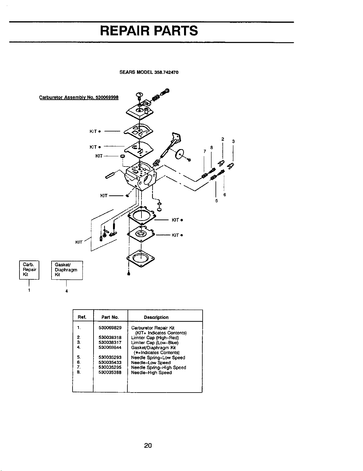
REPAIR PARTS
SEARS MODEL 358.742470
Carburetor Assembly No. 530069998 _ _I_
Gasket/
Diaphragm
_t
r
1 4
KIT •
3-- KIT •
i
Refi PaN No. Descdption
1. 530069829
2.
3.
4.
8.
6.
7.
8.
530038318
530038317
530069844
530035293
530035433
530035295
530035388
Carburetor Repair Kit
(KIT= Indicates Contents)
Limiter Cap (High-Red)
Umiter Cap (Low-Blue)
Gasket/Diaphragm Kit
(•=lndicates Contents)
Needle Spring-Low Speed
Needle-Low Speed
Needle Spring-High Speed
Needle-High Speed
2O
Declaraci6n de Garantfa 21 Servicie y Ajustes 35
Reglas de Seguridad 21 Almacenaje 37
Montaje 25 Tabla Diagn6stica 38
Uso 28 Piezas de Repuesto
Mantenimiento 34 y Encomiendad Contratapa
GARANTIA COMPLETO DE UN AI_IO PARA LA PODADORA DE MALEZA A
GASOLINA BRUSHWACKER ® DE CRAFTSMAN ® PODADORA CON CUCHIL-
LAS.
Durante un a5o completo, a partir de la fecha de compra, siempre que se haga el
mantenimiento, la lubricaci6n y los ajustes a esta Podadora de Maleza a Gasoli-
na Brushwacker de Craftsman seg_n las instrucciones de use y mantenimiento
en el Manual del Usuario, Sears reparar& cualquier defecto de materiales o de
mano de obra gratuitamente.
Esta garantfa excluye la cuchilla, la linea de nilSn, la bujla y el filtro de aire, que
sen piezas fungibles que se gastan con el uso normal.
Si se usa esta Podadora de Maleza a Gasolina Brushwacker con fines comer-
ciales, esta garantfa tendr_ validez por sSla 90 dias a partir de la fecha de com-
pra. Si se usa esta Podadora de Maleza a Gasolina Brushwacker con fines de
alquiler, esta garantfa tendr_ validez s61amente por 30 dlas a partir de la fecha de
compra. Esta garantia tendr& validez _nicamente mientras se use este producto
dentro de los Estados Unidos.
SE OBTENDRA SERVIClO BAJO GARANTIA DEVOLVIENDO LA PODADORA DE MAL-
EZA BRUSHWACKER AL CENTRO DE SERVICIO SEARS MAS CERCANO EN LOS ES-
TADOS UNIDOS.
Esta garantia confiere derechos legales especfficos al propietario, que tal vez
tenga asimismo otros derechos que varian entre estados.
Sears, Roebuck and Co., D/817 WA Hoffman Estates, IL 60179
_' PELIGRO: Esta herramienta mo-
torizada puede ser peligrosa. Puede
ocasionar lesiones graves, incluso la
amputaci6n o la ceguera, tanto al opera-
dor como a otras personas. Las adver-
tencias e instrucciones de seguridad
contenidas en este manual deben cum-
plirse en todo momento para garantizar
un nivel de seguridad y efectividad razo-
nable durante la utilizaci6n del aparato.
El operador es responsable del cumpli-
miento de las advertencias e instruccio-
nes indicadas en este manual yen el
aparato. Antes de ensamblar y utilizar el
aparato, lea integramente el Manual del
Operador. Limite el uso de este aparato
a personas que previamente hayan lei-
do y comprendido y posteriormente
cumplan, las advertencias e instruccio-
nes indicadas en este manual yen el
aparato. Nunca permita que este apara-
to sea utilizado por ni_os.
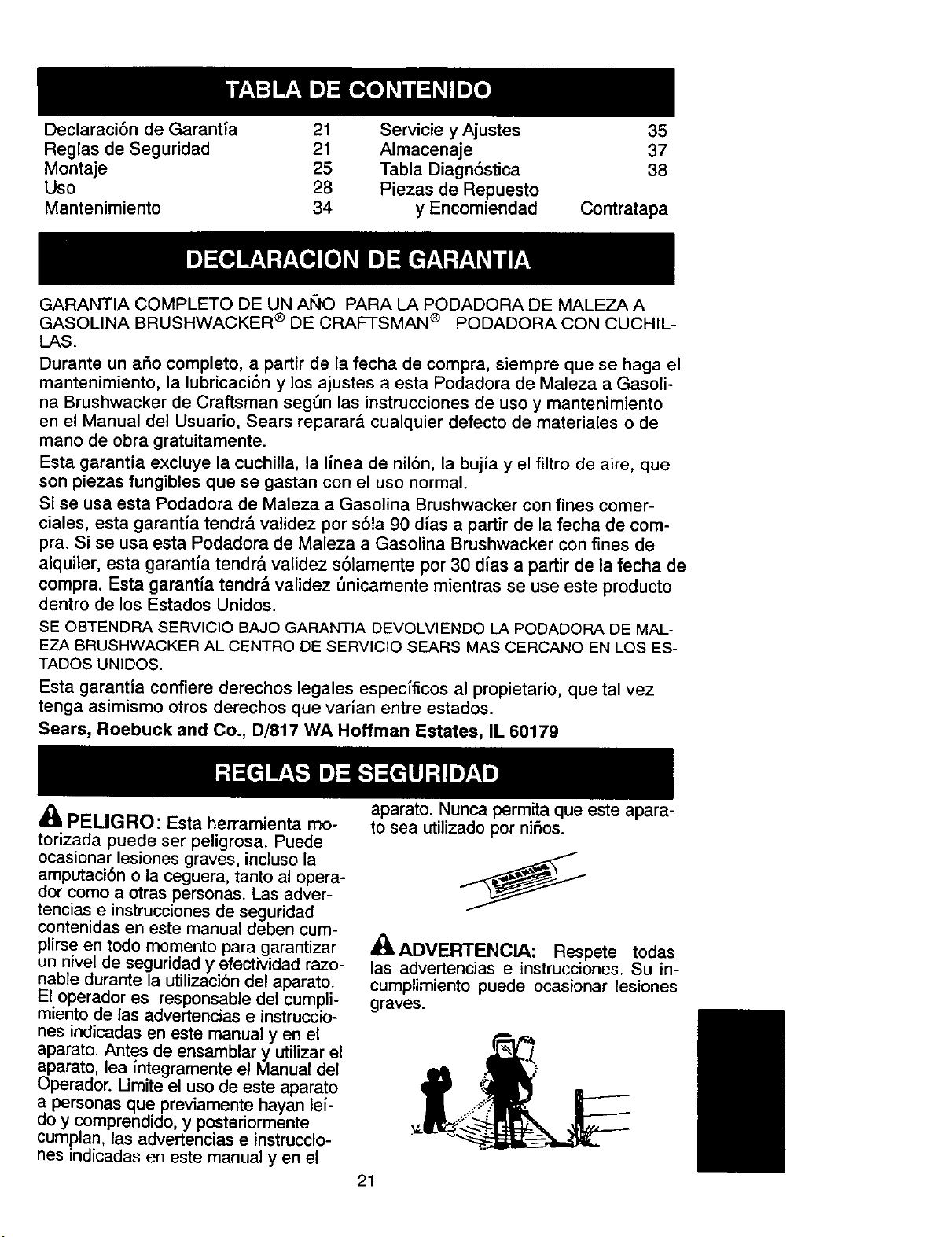
ADVERTENCIA: Respete todas
las advertencias e instrucciones. Su in-
cumplimiento puede ocasionar lesiones
graves.
21
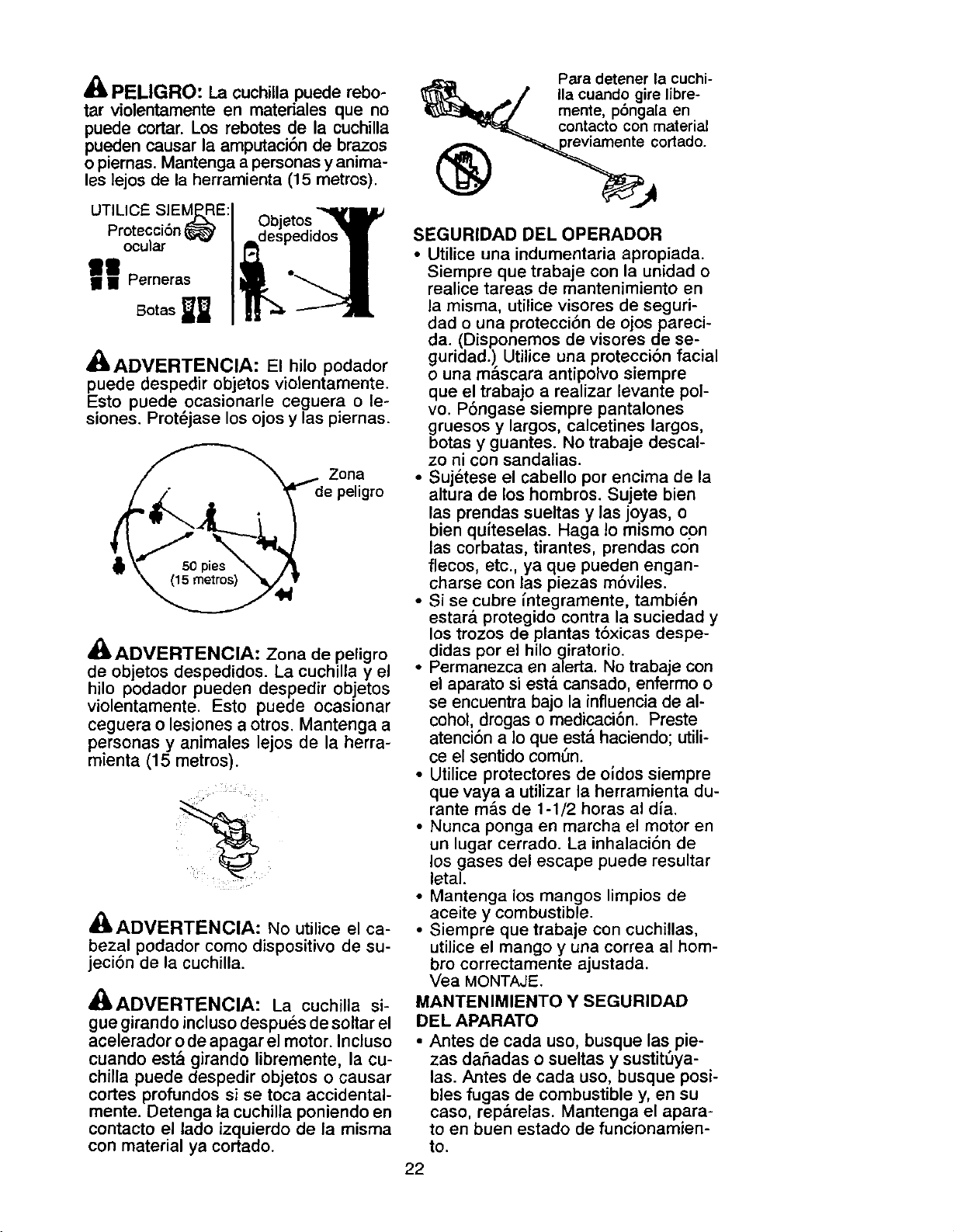
PELIGRO: La cuchilla puede rebo-
tar violentamente en materiales que no
puede cortar. Los rebotes de la cuchilla
pueden causar la amputaci6n de brazos
o piernas. Mantenga a personasy anima-
les lejos de la herramienta (15 metros).
UTILICE SIEM_E:
Protecci6n
ocular
lit
II II Perneras
Botas _
Objetos
despedidos
_,ADVERTENCIA: El hilo podador
puede despedir objetos violentamente.
Esto puede ocasionarle ceguera o le-
siones. Prot_jase los ojos y las piernas.
ADVERTENCIA: Zona de peligro
de objetos despedidos. La cuchilla y el
hilo podador pueden despedir objetos
violentamente. Esto puede ocasionar
ceguera o lesiones a otros. Mantenga a
personas y animales lejos de la herra-
mienta (15 metros).
,_ADVERTENCIA: No utilice el ca-
bezal podador como dispositivo de su-
jeci6n de la cuchilla.
A(_ADVERTENCIA: La cuchilla si-
gue girando incluso despues de soltar el
acelerador o de apagar el motor. Incluso
cuando est& girando libremente, la cu-
chilla puede despedir objetos o causar
cortes profundos si se toca accidental-
mente. Detenga la cuchilla poniendo en
contacto el lado izquierdo de la misma
con material ya cortado.
Para detener la cuchi-
Ila cuando gire libre-
mente, pbngala en
contacto con material
_ cortado.
SEGURIDAD DEL OPERADOR
• Utilice una indumentaria apropiada.
Siempre que trabaje con la unidad o
realice tareas de mantenimiento en
la misma, utilice visores de seguri-
dad o una protecci6n de ojos pareci-
da. (Disponemos de visores de se-
guridad.). Utilice una protecci6n facial
o una mascara antipolvo siempre
que el trabajo a realizar levante pol-
vo. P6ngase siempre pantalones
gruesos y largos, calcetines largos,
botas y guantes. No trabaje descal-
zo ni con sandalias.
• Sujetese el cabello por encima de la
altura de los hombros. Sujete bien
las prendas sueltas y las joyas, o
bien quiteselas. Haga Io mismo con
las corbatas, tirantes, prendas con
flecos, etc., ya que pueden engan-
charse con las piezas m6viles.
• Si se cubre _ntegramente, tambi_n
estar& protegido contra la suciedad y
los trozos de plantas t6xicas despe-
didas por el hilo giratorio.
• Permanezca en alerta. No trabaje con
el aparato si est& cansado, enfermo o
se encuentra bajo la influencia de al-
cohol, drogas o medicaci6n. Preste
atenci6n a Io que est,. haciendo; utili-
ce el sentido com_n.
• Utilice protectores de oidos siempre
que vaya a utilizar la herramienta du-
rante m_s de 1-1/2 horas al dfa.
• Nunca ponga en marcha el motor en
un lugar cerrado. La inhalaci6n de
los gases del escape puede resultar
letal.
• Mantenga los mangos limpios de
aceite y combustible.
• Siempre que trabaje con cuchillas,
utilice el mango y una correa al hom-
bro correctamente ajustada.
Vea MONTAJE.
MANTENIMIENTO Y SEGURIDAD
DEL APARATO
• Antes de cada uso, busque las pie-
zas dahadas o sueltas y sustit_ya-
las. Antes de cada uso, busque posi-
bles fugas de combustible y, en su
caso, rep&relas. Mantenga el apara-
to en buen estado de funcionamien-
to.
22
• Deseche la cuchillas dobladas, den-
tadas, partidas, rotas o deterioradas
de algun modo. Antes de utilizar la
unidad, sustituya las piezas del ca-
bezal podador que esten partidas,
rotas o deterioradas de algi3n modo.
• Realice el mantenimiento del aparato
siguiendo los procedimientos reco-
mendados. Mantenga la cuchilla afila-
da. Mantenga el hilo cortador con la
Iongitud apropiada.
• Utilice exclusivamente hilo con un
di&metro de 0,080 pulgadas (2 mm)
de la marca Craftsman®. Nunca utili-
ce cable, cuerda, alambre, etc.
• Antes de utilizar la unidad, instale la
cubierta protectora apropiada. Utilice
la cubierta metalica siempre que tra-
baje con una cuchilla met&lica. Utili-
ce la cubierta pl&stica siempre que
trabaje con hilo podador.
• Utilice exclusivamente la cuchilla o el
cabezal podador especificado y ase-
gSrese de que est_ correctamente
instalado y firmemente sujeto.
• Nunca ponga en marcha el motor
con el cobertor del embrague des-
montado. El embrague podria des-
prenderse y causar graves lesiones.
• Cerci6rese de que el cabezal poda-
dor se detiene al pasar el motor al
ralenti.
• Antes de realizar cualquier tarea de
mantenimiento (salvo ajustes en el
carburador), desconecte la bujia.
• Realice los ajustes del carburador
con la parte inferior apoyada en alto
para impedir que la cuchilla o el hilo
podador entrenen contacto con al-
gun objeto. Sujete el aparato con las
manos, sin utilizar la correa hombre-
ra.
• Cuando realice ajustes en el carbu-
rador, mantenga alejadas del lugar a
otras personas.
• Utilice exclusivamente los acceso-
rios y recambios recomendados pot
Craftsman.
• Confie todas las tareas de manteni-
miento y reparaci6n no explicadas
en este manual a su Centro de
Servicio de Sears.
SEGURIDAD EN EL USO DE "
COMBUSTIBLE
• Mezcle y vierta el combustible en
exteriores,
• Mantenga el combustible alejado de
chispas y llamas.
• Utilice recipientes homologados para
el uso de combustibles.
• Impida que se fume cetca del com-
bustible o del aparato, tanto si 6ste
se encuentra parado o se est& utili-
zando.
• Antes de porter en marcha el motor,
limpie todo posible resto de combus-
tible derramado.
• Antes de poner en marcha el motor,
al6jese como minimo 3 metros del lu-
gar de repostaje.
• Antes de quitar el tap6n de combus-
tible, detenga el motor y d_jelo en-
friar.
• Antes de guardar el aparato, vacie el
dep6sito de combustible. Arranque
el motor y d6jelo en marcha hasta
que se detenga con el fin de agotar
el combustible que pueda quedar en
el carburador.
• Guarde el aparato y el combustible
en un lugar donde los vapores ema-
nados del combustible no puedan
entrar en contacto con chispas ni lla-
mas procedentes de calentadores
de agua, motores o interruptores
el6ctricos, hornos, etc.
SEGURIDAD EN EL MANEJO
• Antes de cada uso, inspeccione la
zona de trabajo. Retire todos los ob-
jetos (rocas, cristales rotos, clavos,
cables, hilos, etc.) que puedan ser
despedidos o quedar enredados en
la cuchilla o en el cabezal podador.
• Mantenga alejados del lugar de traba-
jo (15 metros) a otras personas, ya
sean ni6os, acompa6antes o ayudan-
tes, y a animales. Detenga el motor
tan pronto como alguien se le aproxi-
me.
• Mantenga siempre el motor junto al
lado derecho de su cuerpo.
• Sujete firmemente la unidad con am-
bas manos.
• Pise con seguridad y mantenga el
equilibrio en todo momento. No esti-
re el cuerpo en exceso.
• Mantenga la cuchilla o cabezal po-
dador por debajo de la cintura.
• No levante el motor por encima de su
cintura.
• Mientras el motor est@ en marcha,
mantenga todas las partes de su
cuerpo alejadas de ta cuchilla odel
cabezal podador, y del silenciador.
• Corte siempre de derecha a izquier-
da.
• Utilice el aparato solamente para las
tareas explicadas en este manual.
23
TRANSPORTE Y ALMACENAMIENTO
• Antes de proceder a su transporte,
detenga el aparato.
• Mantenga el silenciador alejado del
cuerpo.
• Antes de almacenar o transportar el
aparato en un vehiculo, deje enfriar
el motor y sujete bien el aparato.
• Antes de guardar o transportar el
aparato, vacie el depSsito de com-
bustible. Arranque el motor y d_jelo
en marcha hasta que se detenga
con el fin de agotar el combustible
clue pueda quedar en el carburador.
• Guarde el aparato y el combustible
en un lugar donde los vapores ema-
nados del combustible no puedan
entrar en oontacto con chispas ni lla-
mas procedentes de calentadores
de agua, motores 0 interruptores
el_ctricos, hornos, etc.
• Guarde el aparato de modo que la
cuchilla 0 el limitador de hilo no pue-
dan ocasionar lesiones accidental-
mente. Este aparato puede colgarse
por la barra.
• Guarde el aparato fuera del alcance
de los niSos.
NOTA ESPECIAL: Su sierra no viene
equipada con silenciador limitador de
temperatura ni con rejilla antichispa que
cumpla los requisitos de los C6digos de
California 4442 y 4443. Todas las tierras
forestadas federales, m&s los estados
de California, Idaho, Maine, Minnesota,
Nueva Jersey, Washington y OregSn,
requieren pot ley que muchos motores
de combusti6n interna est_n equipados
con rejilla antichispa. Si usted el aparato
donde existen tales reglamento, usted
tiene la responsabilidad juridica de insta-
lar y mantener estas piezas en correcto
estado de funcionamiento. De Io contra-
rio, estar& en infracciSn de la ley.
NOTA ESPECIAL: El estar expuesto
alas vibraciones a travds del uso pro-
Iongado de herramientas de fuerza a
gasolina puede cuasar daSos a los va-
sos sanguineos o a los nervios de los
dedos, las manos y las coyunturas en
aquellas personas que tienen propen-
sidad a los trastornos de la circulaciSn
o alas hinchazones anormales. El uso
prolongado en tiempo frio ha sido aso-
ciado con daSos a los vasos sna-
guineos de personas que por otra
parte se encuentran en perfecto esta-
do de salud. Si ocurren slntomas tales
como el entumecimiento, el dolor, la
falta de fuerza, los cambios en el color
o la textura de la piel o falta de sentido
en los dedos, las manos o las coyun-
turas, deje de usar esta m_.quina in-
mediatamente y procure atenciSn
m_dica. Los sistemas de anti-vibra-
ciSn no garantizan que se eviten tales
problemes. Los usuarios que hacen
uso continuo y prolongando de las
herramientas de fuerza deben fiscali-
zar atentamente su estado fisico y el
estado del aparato.
CONTENIDO DE LA CAJA
Compruebe si la caja contiene los si-
guientes elementos:
Model: 358.742470
• Podadora
• Tornillos del mango (2)
• Tornillos de la cubierta de la cuchilla
(4)
• Arandela abombada
• Tuerca larga para instalar la cuchilla
• Llave hexagonal larga
• Llave hexagonal corta
• Tapa de la abrazadera
• Cubierta met_lica
• Cubierta pl&stica
• Correa al hombro con advertencia
• Cuchilla para hierbas
• Cabezal podador
Man_o
"-Deposito de aceite
Aseg_rese de que ninguna pieza est_
daSada. No utilice piezas dar_adas.
NOTA: Si necesita ayuda o detecta que
alguna pieza falta o est& daSada, Ilame
al 1-800-235-5878.
Es normal que el filtro de combustible
suene en el interior del depSsito de com-
bustible vacio.
Debido a los ajustes y comprobaciones
del carburador que se realizan en f&bri-
ca, es normal que se encuentren algu-
nos restos de combustible o _ceite en el
silenciador.
MONTAJE
,_ ADVERTENClA: Si recibe el apa-
rato ya armado, repita todos los pasos pa-
ra asegurarse de que el aparato estd co-
rrectamente ensamblado y todas las
sujeciones firmes.
HERRAMIENTAS NECESARIAS
• 2 Ilaves hexagonales (incluidas)
• Ilave ajustable o alicates largos
• destornillador Phillips.
24
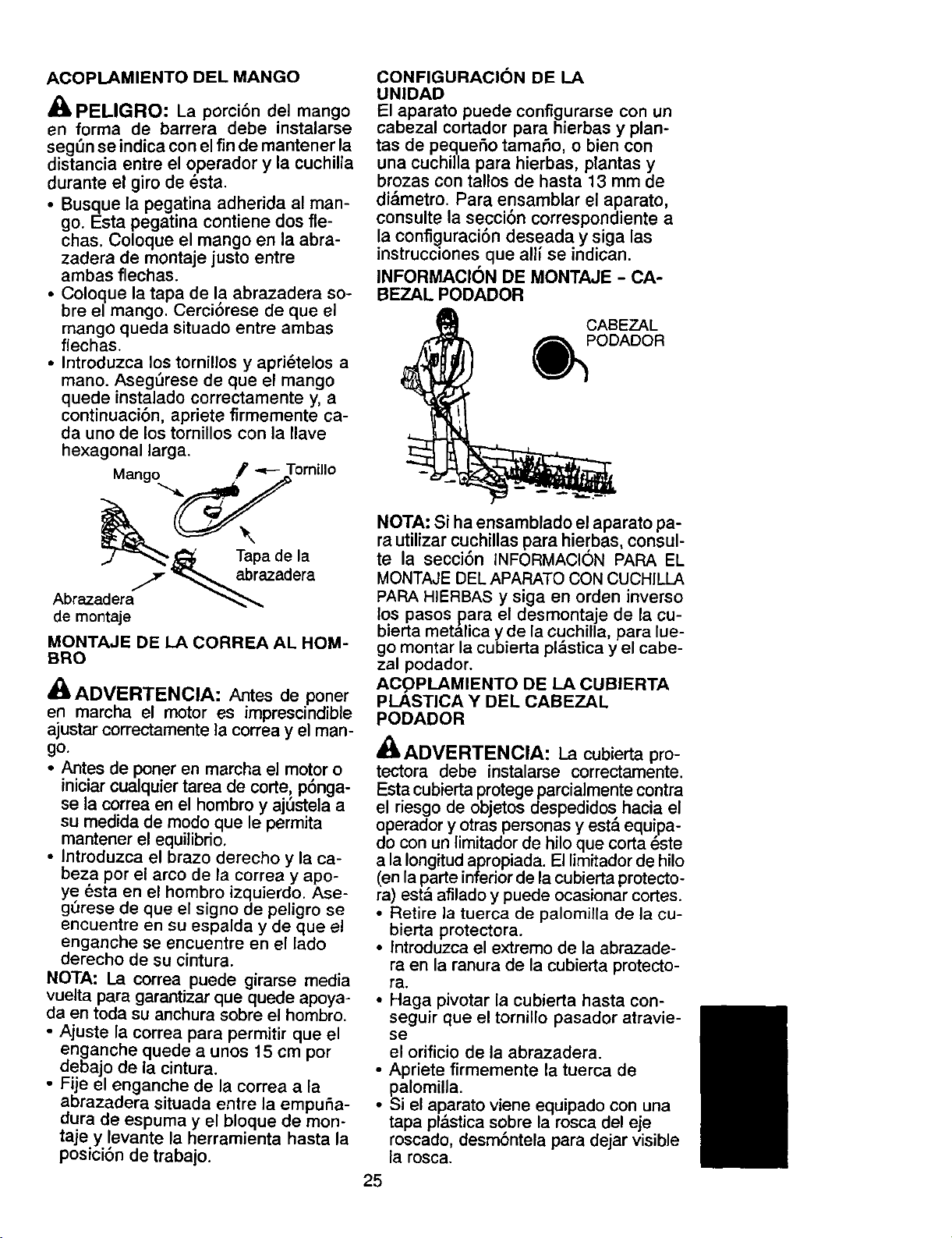
ACOPLAMIENTO DEL MANGO
PELIGRO: La porcibn del mango
en forma de barrera debe instalarse
segL_n se indica con el fin de mantener la
distancia entre el operador y la cuchilla
durante el giro de 6sta.
• Busque la pegatina adherida al man-
go. Esta pegatina contiene dos fie-
chas. Coloque el mango en la abra-
zadera de montaje justo entre
ambas flechas.
• Coloque la tapa de la abrazadera so°
bre el mango. Cerci6rese de que el
mango queda situado entre ambas
flechas.
• Introduzca los tornillos y apri6telos a
mano. AsegSrese de que el mango
quede instalado correctamente y, a
continuaci6n, apriete firmemente ca-
da uno de los tornillos con la Ilave
hexagonal larga.
Mango _' -,,.--Tornillo
/y _.._ abrazadera
Abrazadera _
de montaje
MONTAJE DE I._ACORREA AL HOM-
BRO
_-ADVERTENCIA: Antes de poner
en marcha el motor es imprescindible
ajustar correctamente la correa y el man-
go.
• Antes de poner en marcha el motor o
iniciar cualquier tarea de code, p6nga-
se la correa en el hombro y ajSstela a
su medida de modo que le permita
mantener el equilibrio,
• Introduzca el brazo derecho y la ca-
beza por el arco de la correa y apo-
ye 6ste en el hombro izquierdo. Ase-
gL_rese de que el signo de peligro se
encuentre en su espalda y de que e!
enganche se encuentre en el lado
derecho de su cintura.
NOTA: La correa puede girarse media
vuelta para garantizar que quede apoya-
da en toda su anchura sobre el hombro.
• Ajuste la correa para permitir que el
enganche quede a unos 15 cm por
debajo de la cintura.
• Fije el enganche de la correa a la
abrazadera situada entre la empu_a-
dura de espuma y el bloque de mon-
taje y !evante la herramienta hasta la
posicion de trabajo.
CONFIGURACION DE LA
UNIDAD
El aparato puede configurarse con un
cabezal cortador para hierbas y plan-
tas de pequer_o tamar_o, o bien con
una cuchilla para hierbas, plantas y
brozas con tallos de hasta 13 mm de
di&metro. Para ensamblar el aparato,
consulte la seccibn correspondiente a
la config.uraci6n deseada y siga las
instrucc=onesque allf se indican.
INFORMACION DE MONTAJE - CA-
BEZAL PODADOR
CABEZAL
PODADOR
NOTA: Si ha ensamblado el aparato pa-
rautilizar cuchillas para hierbas, consul-
te la secci6n INFORMAClON PARA EL
MONTAJE DEL APARATO CONCUCHILLA
PAPA HIERBAS y siga en orden inverso
los pasos para el desmontaje de la cu-
bieda met&lica y de la cuchilla, para lue-
go montar la cubieda pl&stica y el cabe-
zal podador.
ACpPLAMIENTO DE LA CUBIERTA
PLASTICA Y DE/CABEZAL
PODADOR
,tt
_ADVERTENCIA: La cubierta pro-
tectora debe instalarse correctamente.
Esta cubierta protege parcialmente contra
el riesgo de objetos despedidos hacia el
operador y otras personas y est_ equ!pa-
do con un limitador de hilo que corta este
a la Iongitud apropiada. El limitador de hilo
(en la parte inferior de la cubierta protecto-
ra) est& afilado y puede ocasionar codes.
• Retire la tuerca de palomitla de la cu-
bierta protectora.
• Introduzca el extremo de la abrazade-
ra en la ranura de la cubierta protecto-
ra.
• Haga pivotar la cubieda hasta con-
seguir que el tomillo pasador atravie-
se
el orificio de la abrazadera.
• Apriete firmemente la tuerca de
palomilla.
• Si el aparato viene equipado con una
tapa pl&stica sobre la rosca del eje
roscado, desm6ntela para dejar visible
la rosca.
25
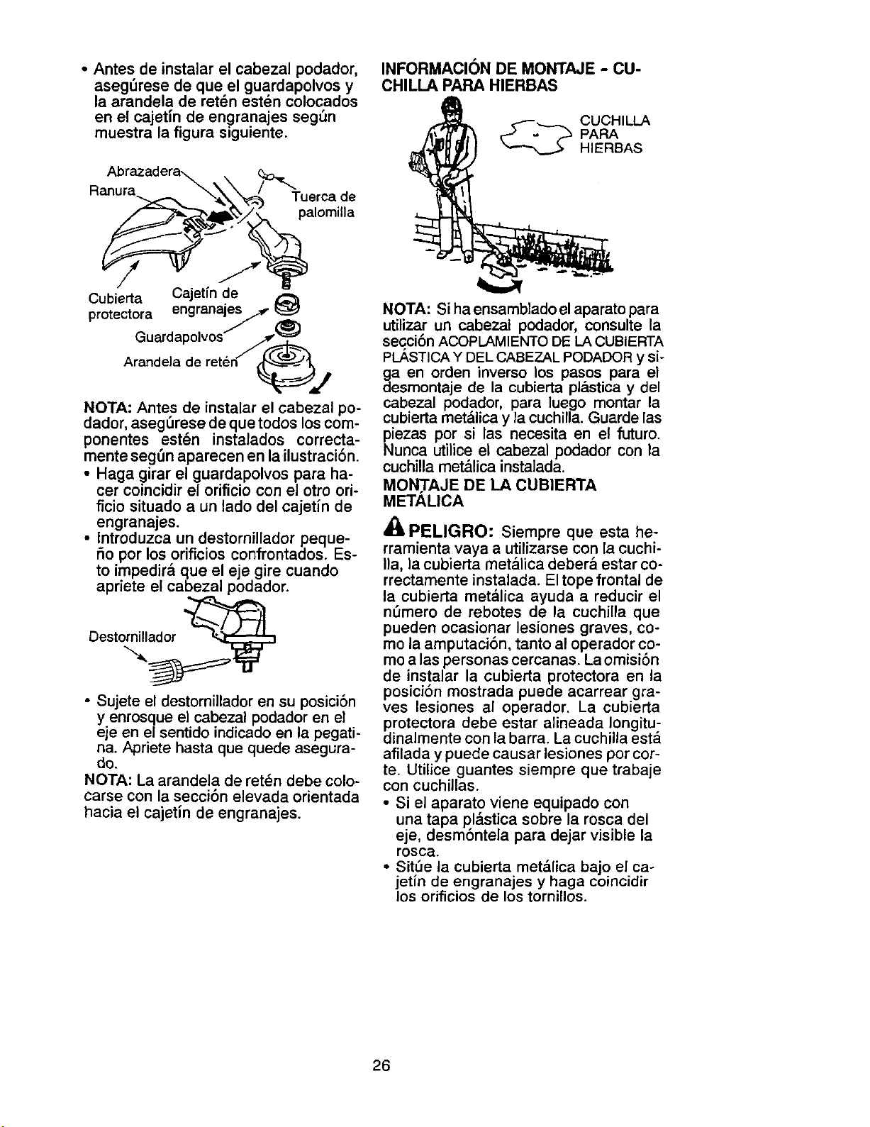
• Antes de instalar el cabezal podador,
asegSrese de que el guardapolvos y
la arandela de ret6n est_n colocados
en el cajetJn de engranajes seg_n
muestra la figura siguiente.
RanAubrl:_a_/_'_Tu erca de
Cubierta Cajetin de
protectora engranales 7
Guardap°lv°sJ/_ _(_(_
Arandela de reten __j
NOTA: Antes de instalar el cabezal po-
dador, aseg_rese de que todos los com-
ponentes est_n instalados correcta-
mente seg_n aparecen en la ilustraci6n.
• Haga girar el guardapolvos para ha-
cer coincidir el orificio con el otro ori-
ficio situado a un lado del cajetin de
engranajes.
• Introduzca un destornillador peque-
r_opor los orificios confrontados. Es-
to impedir& que el eje gire cuando
apriete el cabezal podador.
Destornillador
• Sujete el destornillador en su posici6n
y enrosque el cabezal podador en el
eje en el sentido indicado en la pegati-
na. Apriete hasta que quede asegura-
do.
NOTA: La arandela de ret_n debe colo-
carse con la secci6n elevada orientada
hacia el cajetin de engranajes.
INFORMACION DE MONTAJE - CU-
CHILLA PARA HIERBAS
_.._ UCHILLA
PAPA
HIERBAS
NOTA: Si ha ensamblado el aparato para
utilizar un cabezal podador, consulte la
secci6n ACOPLAMIENTO DE LA CUBIERTA
PLASTICA Y DEL CABEZAL PODADOR y si-
ga en orden inverso los pasos para el
desmontaje de la cubierta pl&stica y del
cabezal podador, para luego montar la
cubierta met_llica y la cuchilla. Guarde las
piezas por si las necesita en el futuro.
Nunca utilice el cabezal podador con la
cuchilla met&lica instalada.
MOWI'AJE DE LA CUBIERTA
METALICA
PELIGRO: Siempre que esta he-
rramienta vaya a utilizarse con la cuchi-
Ila, la cubierta met&lica deber& estar co-
rrectamente instalada. El tope frontal de
la cubierta met&lica ayuda a reducir el
n_mero de rebotes de la cuchilla que
pueden ocasionar lesiones graves, co-
mo la amputaci6n, tanto al operador co-
mo a las personas cercanas. La omisi6n
de instalar la cubierta protectora en la
posici6n mostrada puede acarrear gra-
ves lesiones al operador. La cubierta
protectora debe estar alineada Iongitu-
dinalmente con la barra. La cuchilla est&
afilada y puede causar lesiones por cor-
te. Utilice guantes siempre que trabaje
con cuchillas.
• Si el aparato viene equipado con
una tapa pl&stica sobre la rosca del
eje, desm6ntela para dejar visible la
rosca.
• Sit_e la cubierta met_llica bajo el ca-
jetin de engranajes y haga coincidir
los orificios de los tornillos.
26
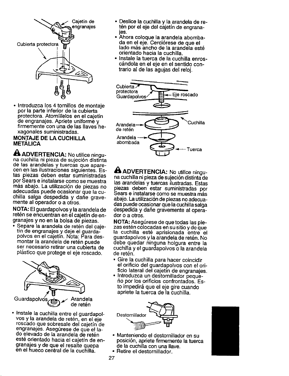
Cubierta protectora
Cajet[n de
engranajes
• Deslice la cuchilla y la arandela de re-
t_n per el eje del cajetin de engrana-
jes.
• Ahora coloque la arandela abomba-
da en el eje. Cerci6rese de que el
lade m&s ancho de la arandela est_
orientado hacia la cuchilla.
• Instale la tuerca de la cuchilla enros-
c&ndola en el eje en el sentido con-
trario al de las agujas del reloj.
• Introduzca los 4 tornillos de montaje
per la parte inferior de la cubierta
protectora. Atorn[llelos en el cajetin
de engranajes. Apriete uniforme y
firmemente con una de las Ilaves he-
xagonales suministradas.
MON,TAJE DE LA CUCHILLA
METALICA
_, ADVERTENCIA: No util!ce ningu-
na cuchilla ni pieza de sujecion distinta
de las arandelas y tuercas que apare-
cen en las ilustraciones siguientes. Es-
tas piezas deben estar suministradas
per Sears e instalarse come se rnuestra
m_.s abajo. La utilizaci6n de piezas no
adecuadas puede ocasionar que la cu-
chilla salga despedida y daSe grave-
mente al operador o a otros.
NOTA: El guardapolvos y laarandela de
retch se encuentran en el cajetfn de en-
granajes y no en la bolsa de piezas.
• Separe la arandela de ret_n del caje-
tin de engranajes y deje el guarda-
pelves en el cajetm. Nota: Para des-
montar la arandela de ret_n puede
set necesario retirar una cubierta de
pl&stico que protege el eje roscado.
Guardapolvds(_ _,/ deArandelaret_n
• Instale la cuchilla entre el guardapol-
yes y la arandela de ret_n, en el, eje
rescado.que sobresale del cajetm de
engranajes. AsegL_rese de que el la-
de elevado de la arandela de ret_n
est_ orientado hacia el cajetfn de en-
granajes y de que el resalte quepa
en el hueco central de la cuchilla.
•,,---i....__ ,..._.,.....
Cubierta_='_i_='r%_
protectora _.
Guardapolvos/ _1-.=-- _-Jeroscado
Arandela---_- _ _'Cuchilla
de ret_n
Arandela ---_-_
abombada
_ -.F---muerca
_;)&ADVERTENCIA: No utilice ningu-
na cuchillani pieza de sujeci6n distinta de
las arandelas y tuercas ilustradas. Estas
piezas deben estar suministradas per
Sears e instalarse come se rnuestramas
abajo. La utilizaci6nde piezas noadecua-
das puede ocasionarque lacuchillasalga
despedida y daSe gravemente al opera-
dor o a otros.
NOTA: AsegSrese de quetodas las pie-
zas est_n celocadas en su sitioy de que
la cuchilla est_ aprisionada entre el
guardapolvos y la arandela de ret6n. No
debe quedar ninguna holgura entre la
cuchilla y el guardapolvos o la arandela
de ret6n.
• Gire la cuchilla para hacer coincidir
el oriflcio del guard.a,polvos con el ori-
ficio lateral del cajetm de engranajes.
• Introduzca un destornillador peque-
5o per los orificios confrontados. Es-
to impedir& que el eje gire cuando
apriete la tuerca de la cuchilla.
• Manteniendo el destornillador en su
posici6n, apriete firmemente la tuerca
de la cuchilia con una Ilave.
• Retire el destornillador.
27
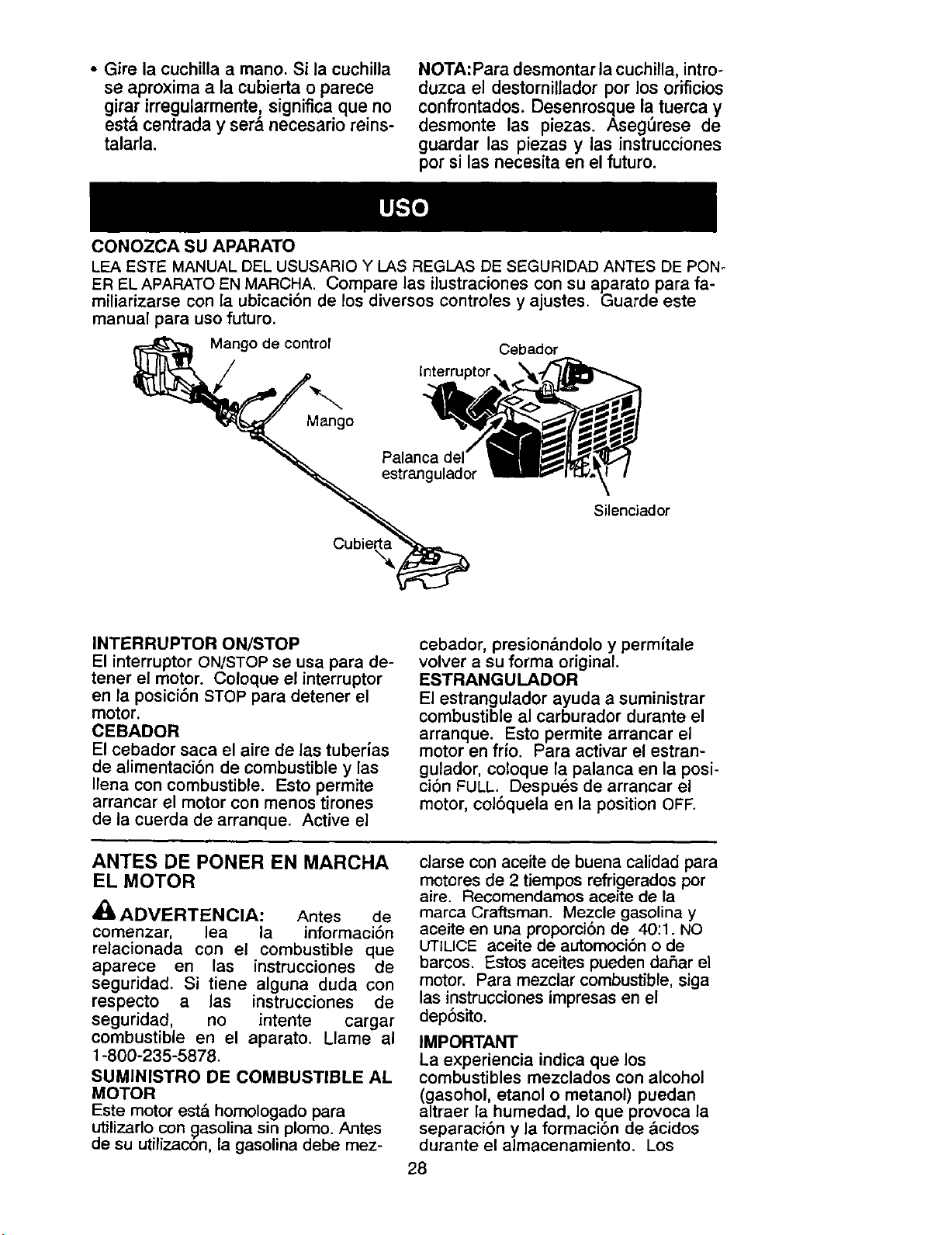
• Gire la cuchilla a mano. Si la cuchilla
se aproximaa la cubiertao parece
girarirregularmente,significaque no
est¢raday ser&necesado reins-
talarla.
CONOZCA SU APARATO
NOTA:Para desmontar ia cuchilla, intro-
duzca el destornillador por los oriflcios
confrontados. Desenrosque la tuerca y
desmonte las piezas. Aseg_rese de
guardar las piezas y las instrucciones
por si las necesita en el futuro.
LEA ESTE MANUAL DEL USUSARIO Y LAS REGLAS DE SEGURIDAD ANTES DE PON-
ER EL APARATO EN MARCHA. Compare las ilustraciones con su aparato para fa-
miliarizarse con la ubicaci6n de los diversos controles y ajustes. Guarde este
manual para uso futuro.
Mango de control
Cebador
lnterruptor,
Mango
Silenciador
INTERRUPTOR ON/STOP
El interruptor ON/STOP se usa para de-
tener el motor. Coloque el interruptor
en la posici6n STOP para detener el
motor.
CEBADOR
El cebador saca el aire de las tuberias
de alimentaci6n de combustible y las
Ilena con combustible. Esto permite
arrancar el motor con menos tirones
de la cuerda de arranque. Active el
cebador, presion&ndolo y permitale
volver a su forma original.
ESTRANGULADOR
El estrangulador ayuda a suministrar
combustible al carburador durante el
arranque. Esto permite arrancar el
motor en fr{o. Para activar el estran-
gulador, coloque la palanca en la posi-
ci6n FULL. Despu_s de arrancar el
motor, col6quela en la position OFF.
ANTES DE PONER EN MARCHA
EL MOTOR
,i_ ADVERTENCIA: Antes de
comenzar, lea la informaci6n
relacionada con el combustible que
aparece en las instrucciones de
seguridad. Si tiene alguna duda con
respecto a las instrucciones de
seguridad, no intente cargar
combustible en el aparato. Llame al
1-800-235-5878.
SUMINISTRO DE COMBUSTIBLE AL
MOTOR
Este motor est_ homologado para
utilizarlo con gasolina sin plomo. Antes
de su utilizac6n, la gasolina debe mez-
clarse con aceite de buena calidad para
motores de 2 tiempos refrigerados por
aire. Recomendamos aceite de la
marca Craftsman. Mezcle gasolina y
aceite en una proporci6n de 40:1. NO
UTILICE aceite de automoci6n o de
barcos. Estos aceites pueden daflar el
motor. Para mezclar combustible, siga
las instrucciones impresas en el
dep6sito.
IMPORTANT
La experiencia indica que los
combustibles mezclados con alcohol
(gasohol, etanol o metanol) puedan
altraer la humedad, Io que provoca la
separaci6n y la formaci6n de &cidos
durante el almacenamiento. Los
28
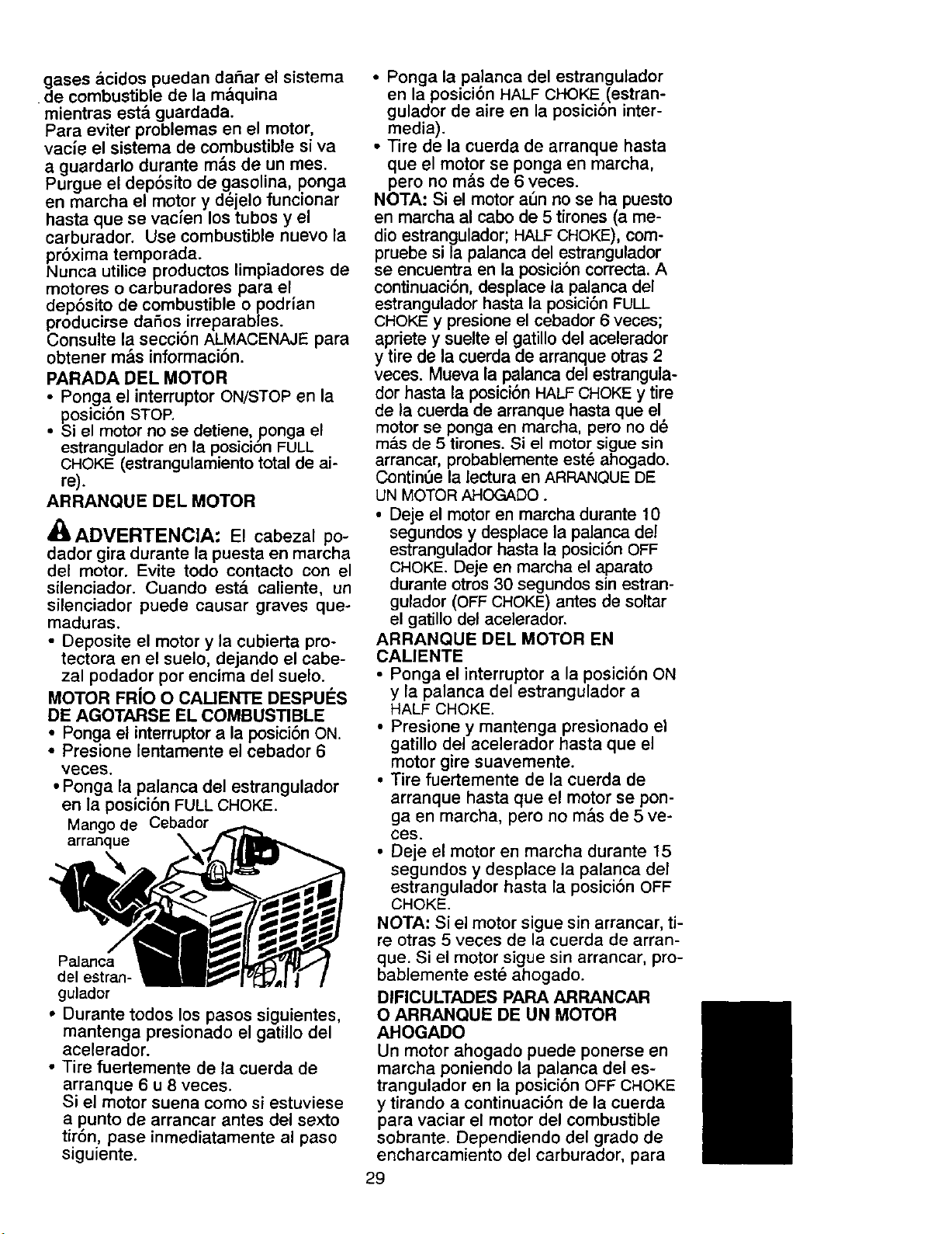
gases _icidos puedan dafiar el sistema
de combustible de la m&quina
mientras est& guardada.
Para eviter problemas en el motor,
vacie el sistema de combustible siva
a guardarlo durante m&s de un mes.
Purgue el dep6sito de .g.asolina, ponga
en marcha el motor y dejelo funcionar
hasta que se vacfen los tubos y el
carburador. Use combustible nuevo la
pr6xima temporada.
Nunca utilice productos limpiadores de
motores o carburadores para el.
deposito de combustible o podnan
producirse daSos irreparables.
Consulte la secci6n ALMACENAJE para
obtener m&s informaci6n.
PARADA DEL MOTOR
• Pon.ga el interruptor ON/STOP en la
posJcEon STOP.
• Si el motor no se detiene, ponga el
estrangulador en la posicion FULL
CHOKE (estrangulamiento total de ai-
re).
ARRANQUE DEL MOTOR
_ADVERTENClA: El cabezal po-
dador gira durante la puesta en marcha
del motor. Evite todo contacto con el
silenciador. Cuando est,. caliente, un
silenciador puede causar graves que-
maduras.
• Deposite el motor y la cubierta pro-
tectora en el suelo, dejando el cabe-
zal podador per encima del suelo.
MOTOR FRiO O CAUENTE DESPUES
DE AGOTARSE EL COMBUSTIBLE
• Ponga el interruptor a la posici6n ON.
• Presione lentamente el cebador 6
veces.
• Ponga la palanca del estrangulador
en la posici6n FULL CHOKE.
Mango de Cebador
arranque \
Palanca
del estran-
gulador
• Durante todos los pasos siguientes,
mantenga presionado el gatillo del
acelerador.
• Tire fuertemente de la cuerda de
arranque 6 u 8 veces.
Si el motor suena como si estuviese
a punto de arrancar antes del sexto
tir6n, pase inmediatamente al paso
siguiente.
• Ponga la palanca del estrangulador
en la posici6n HALF CHOKE (estran-
gulador de aire en la posici6n inter-
media).
• Tire de la cuerda de arranque hasta
que el motor se ponga en marcha,
pero no m&s de 6 veces.
NOTA: Si el motor a6n no se ha puesto
en marcha al cabo de 5 tirones (a me-
dio estrangulador; HALF CHOKE), com-
pruebe si la palanca del estrangulador
se encuentra en la posici6n correcta. A
continuaci6n, desplace la palanca del
estrangulador hasta la posici6n FULL
CHOKE y presione el cebador 6 veces;
apriete y suelte el gatillo del acelerador
y tire de la cuerda de arranque otras 2
veces. Mueva la palanca del estrangula-
dor hasta la posici6n HALF CHOKE y tire
de la cuerda de arranque hasta que el
motor se ponga en marcha, pero no d_
m&s de 5 tirones. Si el motor sigue sin
arrancar, probablemente est_ ahogado.
ContinOe la lectura en ARRANQUE DE
UN MOTOR AHOGADO.
• Deje el motor en marcha durante 10
segundos y desplace la palanca del
estrangulador hasta la posici6n OFF
CHOKE. Deje en marcha el aparato
durante otros 30 segundos sin estran-
gulador (OFF CHOKE) antes de soltar
el gatillo del acelerador.
ARRANQUE DEL MOTOR EN
CALIENTE
• Ponga el interruptor a la posici6n ON
y la palanca del estrangulador a
HALF CHOKE.
• Presione y mantenga presionado el
gatillo del acelerador hasta que el
motor gire suavemente.
• Tire fuertemente de la cuerda de
arranque hasta que el motor se pon-
ga en marcha, pero no mas de 5 ve-
ces.
• Deje el motor en marcha durante 15
segundos y desplace la palanca del
estrangulador basta la posici6n OFF
CHOKE.
NOTA: Si el motor sigue sin arrancar, ti-
re otras 5 veces de la cuerda de arran-
que. Si el motorsigue sin arrancar, pro-
bablemente este ahogado.
DIFICULTADES PARA ARRANCAR
O ARRANQUE DE UN MOTOR
AHOGADO
Un motor ahogado puede ponerse en
marcha poniendo la palanca del es-
trangulador en la posici6n OFF CHOKE
y tirando a continuaci6n de la cuerda
para vaciar el motor del combustible
sobrante. Dependiendo del grado de
encharcamiento del carburador, para
29
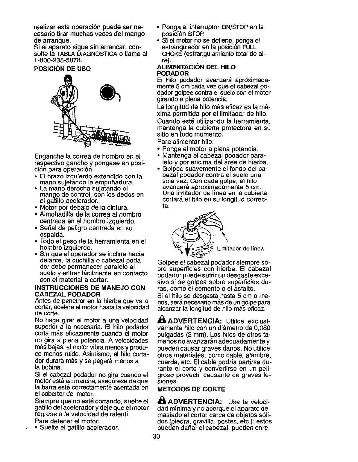
realizar esta operacibn puede ser ne-
cesario tirar muchas veces del mango
de arranque.
Si el aparato sigue sin arrancar, con-
suite la TABLA DIAGNOSTICA o llame al
1-800-235-5878.
POSICION DE USO
Enganche la correa de hombro en el
re spectivo gancho y pongase en posi-
clon para operaclon.
• El brazo izquierdo extendido con la
mano sujetando la empuSadura.
• La mano derecha sujetando el
mango de control, con los dedos en
el gatillo acelerador.
• Motor por debajo de la cintura.
• Almohadilla de la correa al hombro
centrada en el hombro izquierdo.
• Serial de peligro centrada en su
espalda.
• Todo el peso de la herramienta en el
hombro izquierdo.
• Sin que el operador se incline hacia
delante, la cuchilla o cabezal poda-
dor debe permanecer paralelo al
sue]o y entrar f&cilmente en contacto
con el material a cortar.
INSTRUCCIONES DE MANEJO CON
CABEZAL PODADOR
Antes de penetrar en la hierba que va a
cortar, acelere el motor hasta la velocidad
de corte.
No haga girar el motor a una velocidad
superior a la necesaria. El hilo podador
corta m&s eficazmente cuando el motor
no gira a plena potencia. A velocidades
m&s bajas, el motor vibra menos y produ-
ce menos ruido Asimismo, el hilo corta-
dor durara m&s y se pegar& menos a
la bobina
Si el cabezal podador no gira cuando el
motor est& en marcha, asegurese de que
la barra est_ correctamente asentada en
el cobertor del motor.
Siempre que no est_ cortando, suelte el
gatillo del acelerador y deje que el motor
regrese a la velocidad de ralenti.
Para detener el motor:
• Suelte el gatillo acelerador
• Ponga el interruptor ON/STOP en la
posJclon STOP.
• Si el motor no se detiene_ ?onga el
estrangulador en la posiczon FULL
CHOKE (estrangulamiento total de ai-
re).
ALIMENTACION DEL HILO
PODADOR
El hilo podador avanzar_ aproximada-
mente 5 cm cada vez que el cabezal po-
dador golpee contra el suelo con el motor
girando a plena potencia
La Iongitud de hilo m&s eficaz es la m_.-
xima permitida por el limitador de hilo
Cuando est_ utilizando la herramienta,
mantenga la cubierta protectora en su
sitio en todo momento.
Para alimentar hilo:
• Ponga el motor a plena potencia.
• Mantenga el cabezal podador para-
lelo y por encima del &rea de hierba.
• Golpee suavemente el fondo del ca-
bezal podador contra el suelo una
so]a vez. Con cada golpe, el hilo
avanzar& aproximadamente 5 cm
Una limitador de llnea en la cubierta
cortar& el hilo en su Iongitud correc-
ta
_"__; Umitador
V_;: _ de llnea
Golpee el cabezal podador siempre so-
bre superficies con hierba. El cabezal
podador puede sufrir un desgaste exce-
sivo si se golpea sobre superficies du-
ras, como el cemento o el asfalto.
Si el hilo se desgasta hasta 5 cm o me-
nos, ser& necesario m_s de un golpe para
alcanzar la Iongitud de hilo m_.s eficaz.
_(_ADVERTENCIA: Utilice exclusi-
vamente hilo con un di_metro de 0,080
pulgadas (2 mm). Los hilos de ctros ta-
maSos no avanzar&n adecuadamente y
pueden causar graves daSos. No utilice
otros materiales, como cable, alambre,
cuerda, etc. El cable podria partirse du-
rante el corte y convertirse en un peli-
groso proyectil causante de graves le-
siones.
METODOS DE CORTE
_(_kADVERTENCIA: Use la veloci-
dad minima y no acerque el aparato de-
masiado al cortar cerca de objetos s61i-
dos (piedra, gravilla, postes, etc.): estos
pueden daSar el cabezal, pueden enre-
3O
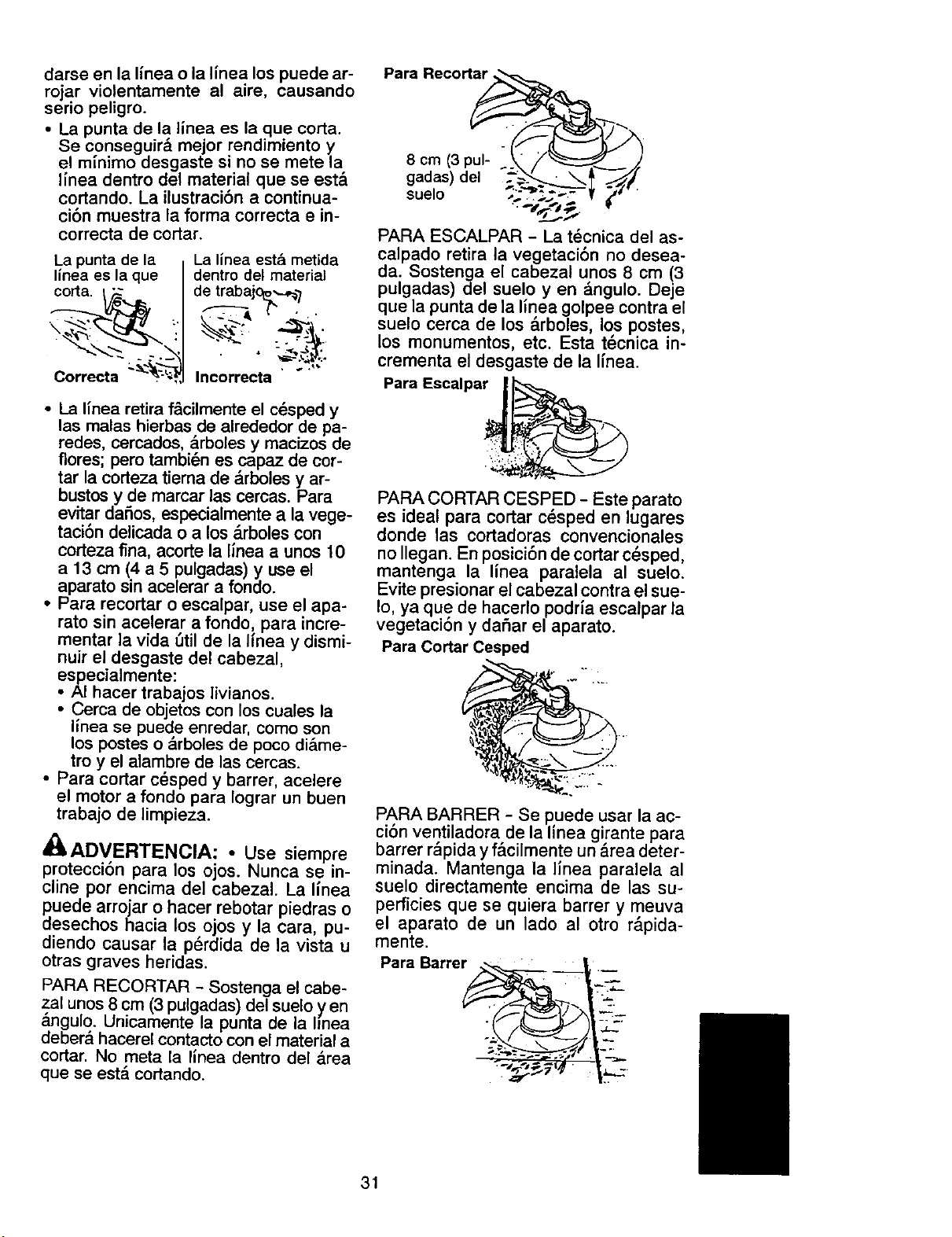
dameenla I_neao la llnea los puede ar-
rojar violentamente al aire, causando
serio peligro.
• La punta de la llnea es la que corta.
Se conseguir& mejor rendirniento y
el rninimo desgaste si no se mete la
Ifnea dentro del material que se est&
cortando. La ilustraci6n a continua-
ci6n muestra la forma correcta e in-
correcta de cortar.
La punta de la
l/nea es la que
corta.
Correcta __"_'-':_
La linea esta metida
dentro del material
de trabajc_._,¢/
• , _._,._ ...
Incorrecta
• La I{nea retira f&cilmenteel c_sped y
las malas hierbas de alrededor de pa-
redes, cercados, &rboles y macizos de
flores; pero tarnbi_n es capaz de cor-
tar la corteza tiema de arboles y ar-
bustos y de marcar las cercas. Para
evitar daSos, especialmente a la vege-
taci6n deiicada o a los &rboles con
corteza fina, acorte la linea a unos 10
a 13 cm (4 a 5 pulgadas) y use el
aparato sin acelerar a fondo.
• Para recortar o escalpar, use el apa-
rate sin acelerar a fondo, para incre-
rnentar ]a vida util de la hnea y dismi-
nuir el desgaste del cabezal,
especialmente:
• AI hacer trabajos livianos.
• Cerca de objetos con los cuales la
linea se puede enredar, come son
los postes o &rboles de poco di_ime-
troy el alambre de las cercas.
• Para cortar c_sped y barrer, acelere
el motor a fondo para Iograr un buen
trabajo de limpieza.
_ADVERTENCIA: • Use siempre
protecci6n para los ojos. Nunca se in-
cline por encirna del cabezal. La linea
puede arrojar o hacer rebotar piedras o
desechos hacia los ojos y la cara, pu-
diendo causar la perdida de la vista u
otras graves heridas.
PARA RECORTAR - Sostenga el cabe-
zal unos 8 cm (3pulgadas) del suelo yen
_ngulo. Unicamente la punta de la linea
deber& hacerel contacto con el material a
cortar. No meta la llnea dentro del &rea
que se est_ cortando.
Para Recortar___ /
8 cm (3pul- ._
gadas) del _'_i_
suelo _.. ,;._,.
•_1,,.".,
"/L.,
PARA ESCALPAR - La
t
tecnica del as-
calpado retira la vegetaci6n no desea-
da. Sostenga el cabezal unos 8 cm (3
pulgadas) del suelo yen &ngulo. Deje
que la punta de la linea golpee contra el
suelo cerca de los arboles, los postes,
los monumentos, etc. Esta tecnica in-
crementa el desgaste de la linea.
Para Escalpar / _!_
PARA CORTAR CESPED - Este parato
es ideal para cortar cesped en lugares
donde las cortadoras convencionales
no Ilegan. En posici6n de cortar c_sped,
mantenga la linea paralela al suelo.
Evite presionar el cabezal contra el sue-
Io, ya que de hacerlo podria escalpar la
vegetaci6n y dafiar el aparato.
Para Cortar Cesped
PARA BARRER - Se puede usar la ac-
cibn ventiladora de la linea girante para
barrer r_pida y f&cilmente un &rea deter-
minada. Mantenga la linea paralela al
suelo directamente encima de las su-
perficies que se quiera barrer y meuva
el aparato de un lado al otro r&pida-
mente.
Para Barre_. ----
31
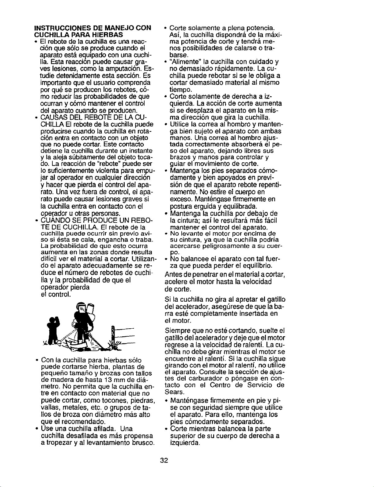
INSTRUCCIONES DE MANEJO CON
CUCHILLA PARA HIERBAS
• El rebote de la cuchilla es una reac-
ci6n que s61o se produce cuando el
aparato est& equipado con una cuchi-
Ila. Esta reacci6n puede causar gra-
ves lesiones, como la amputaci6n. Es-
tudie detenidamente esta secci6n. Es
importante que el usuario comprenda
por qu_ se producen los rebotes, c6-
mo reducir las probabilidades de que
ocurran y c6mo mantener el control
del aparato cuando se producen.
• CAUSAS DEL REBOTE DE LA CU-
CHILLA El rebote de la cuchilla puede
p.roducirse cuando la cuchilla en rota-
cJon entra en contacto con un objeto
que no puede cortar. Este contacto
detiene la cuchilla durante un instante
_la aleja sSbitamente del objeto toca-
o. La reacci6n de "rebote" puede ser
Io suficientemente violenta para empu-
jar al operador en cualquier direcci6n
y hacer que pierda el control del apa-
rato. Una vez fuera de control, el apa-
rato puede causar lesiones graves si
la cuchilla entra en contacto con el
ope,rador u otras personas.
• CUANDO SE PRODUCE UN REBO-
TE DE CUCHILLA. El rebote de la
cuchilla puede ocurrir sin previo avi-
so si _sta se cala, engancha o traba.
La probabilidad de que esto ocurra
aumenta en las zonas donde resulta
dificil ver el material a cortar. Utilizan-
do el aparato adecuadamente se re-
duce el nOmero de rebotes de cuchi-
Ila y la probabilidad de que el
operador pierda
el control.
• Con la cuchilla para hierbas s61o
puede cortarse hierba, plantas de
pequeSo tamaSo y brozas con tallos
de madera de hasta 13 mm de di&-
metro. No permita que la cuchilla en-
tre en contacto con material que no
puede cortar, como tocones, piedras,
o
vallas, metales, etc. grupos deta-
llos de broza con diametro m&s alto
que el recomendado.
• Use una cuchilla afilada. Una
cuchilla desafilada es m&s propensa
a tropezar y al levantamiento brusco.
• Corte solamente a plena potencia.
Asl, la cuchilla dispondra de la m&xi-
ma potencia de corte y tendr& me-
nos posibilidades de calarse o tra-
barse.
• "Alimente" la cuchilla con cuidado y
no demasiado r_pidamente. La cu-
chiila puede rebotar si se le obliga a
codar demasiado material al mismo
tiempo.
• Corte solamente de derecha a iz-
quierda. La acci6n de corte aumenta
si se desplaza el aparato en la mis-
ma direcci6n que gira la cuchilla.
• Utilice la correa al hombro y manten-
ga bien sujeto el aparato con ambas
manos. Una correa al hombro ajus-
tada correctamente absorber& el pe-
so del aparato, dejando libres sus
brazos y manos para controlar y
guiar el movimiento de corte.
• Mantenga los pies separados c6mo-
damente y bien apoyados en previ-
si6n de que el aparato rebote repenti-
namente. No estire el cuerpo en
exceso. Mantengase firmemente en
postura erguida y equilibrada.
• Mantenga la cuchilla por debajo de
la cintura; asi le resultar& m&s f_lcil
mantener el control del aparato.
• No levante el motor por encima de
su cintura, ya que la cuchilla podria
acercarse peligrosamente a su cuer-
po.
• No balancee el aparato con tal fuer-
za que pueda perder el equilibrio.
Antes de penetrar en el material a cortar,
acelere el motor hasta la velocidad
de corte.
Si la cuchilla no gira al apretar el gatillo
del acelerador, asegurese de que la ba-
rra estd completamente insertada en
el motor.
Siempre que no este cortando, suelte el
gatillo del acelerador y deje que el motor
regrese a la velocidad de ralenti. La cu-
chilla no debe girar mientras el motor se
encuentre al ralentL Si la cuchilla sigue
girando con el motor al ralenti, no utilice
el aparato. Consulte la secci6n de ajus-
tes del carburador o p6ngase en con-
tacto con el Centro de Servicio de
Sears.
• Mant_ngase firmemente en pie y pi-
se con seguridad siempre que utilice
el aparato. Para ello, mantenga los
pies c6modamente separados.
• Corte mientras balancea la parte
superior de su cuerpo de derecha a
izquierda.
32
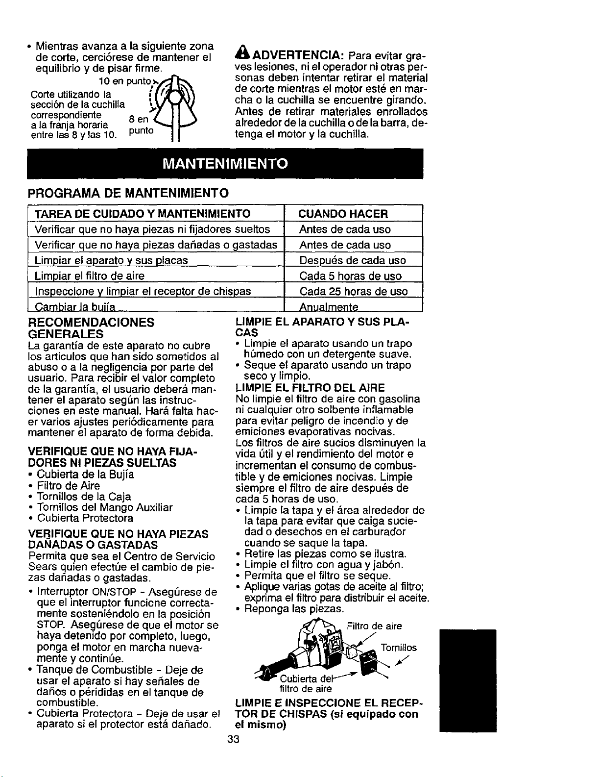
• Mientrasavanza a la siguiente zona
de corte, cerci6rese de mantener el
equilibrio y de pisar flrme.
10 en punto_/,_
Corte utilizando la , f 12"_\\
secci6n de !a cuchilla ',.,V'_-t_J
correspondlente 8 en 7 II \
a la franja horaria . ",,,,I I.,../
entre las 8 y las 10. punlo I I
PROGRAMA DE MANTENIMIENTO
ADVERTENCIA: Para evitar gra-
ves lesiones, ni el operador ni otras per-
sonas deben intentar retirar el material
de corte mientras el motor estd en mar-
cha o la cuchilla se encuentre girando.
Antes de retirar materiales enrollados
alrededor de la cuchilla ode la barra, de-
tenga el motor y la cuchilla.
TAREA DE CUIDADO Y MANTENIMIENTO
Verificar que no haya piezas ni fijadores sueltos
Verificar que no haya piezas dar]adas o gastadas
Limpiar el aparato y sus placas
Limpiar el filtro de aire
Inspeccione y limpiar el receptor de chispas
Cambiar la buifa
CUANDO HACER
Antes de cada uso
Antes de cada uso
Despu6s de cada uso
Cada 5 horas de uso
Cada 25 horas de uso
Anualmente
RECOMENDACIONES
GENERALES
La garantla de este aparato no cubre
los articulos que ban sido sometidos al
abuso o a la negligencia pot parte del
usuario. Para recibir el valor completo
de la garantia, el usuario deber& man-
tener el aparato seg_n las instruc-
ciones en este manual. Har& falta hac-
er ratios ajustes peri6dicamente para
mantener el aparato de forma debida.
VERIFIQUE QUE NO HAYA FIJA-
DORES NI PIEZAS SUELTAS
• Cubierta de la Bujia
• Filtro de Aire
• Tornillos de la Caja
• Tornillos del Mango Auxiliar
• Cubierta Protectora
VERIFIQUE QUE NO HAYA PIEZAS
DAI_IADAS O GASTADAS
Permita que sea el Centro de Servicio
Sears quien efect_e el cambio de pie-
zas daAadas o gastadas.
• Interruptor ON/STOP - AsegSrese de
que el interrupter funcione correcta-
mente sosteni_ndolo en la posici6n
STOP. Aseg_rese de que el motor se
haya detenido por completo, luego,
ponga el motor en marcha nueva-
mente y continue.
• Tanque de Combustible - Deje de
usar el aparato si hay set]ales de
daAos o p_rididas en el tanque de
combustible.
• Cubierta Protectora - Deje de usar el
aparato si el protector est& daAado.
LIMPIE EL APARATO Y SUS PLA-
CAS
• Limpie el aparato usando un trapo
h0medo con un detergente suave.
• Seque el aparato usando un trapo
seco y limpio.
LIMPIE EL FILTRO DEL AIRE
No limpie el filtro de aire con gasolina
ni cualquier otro solbente inflamable
para evitar peligro de incendio y de
emiciones evaporativas nocivas.
Los filtros de aire sucios disminuyen la
vida 5til y el rendimiento del motor e
incrementan el consumo de combus-
tible y de emiciones nocivas. Limpie
siempre el filtro de aire despu_s de
cada 5 horas de uso.
• Limpie la tapa y el &rea alrededor de
la tapa para evitar que caiga sucie-
dad o desechos en el carburador
cuando se saque la tapa.
• Retire las piezas como se ilustra.
• Limpie el filtro con agua y jab6n.
• Permita que el filtro se seque.
• Aplique varias gotas de aceite al filtro;
exprima el filtro para distribuir el aceite.
• Reponga las piezas.
Filtro de aire
Tornillos
J
Cubierta del-I"_"
filtro de aire
LIMPIE E INSPECCIONE EL RECEP-
TOR DE CHISPAS (si equipado con
el mismo)
33
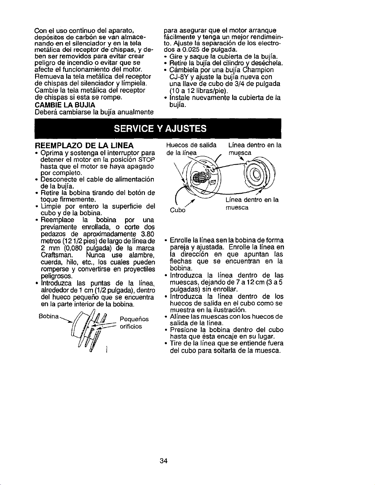
Con el uso continuo del aparato,
depbsitos de carbbn se van almace-
nand o en el silenciador yen la tela
metalica del receptor de chispas, y de-
ben set removidos para evitar crear
peligro de incendio o evitar que se
afecte el funcionamiento del motor.
Remueva la tela met_.lica del receptor
de chispas del silenciador y limpiela.
Cambie la tela met&lica del receptor
de chispas siesta se rompe.
CAMBIE LA BUJIA
Deber_. cambiarse la bujia anualmente
para asegurar que el motor arranque
f_lcilmente y tenga un mejor rendimein-
to. Ajuste la separaci&n de los electro-
dos a 0.025 de pulgada.
Gire y saque la cubierta de [a buj{a.
i Retire la del cilindro des_chela.
bujfa
Y
C&mbiela por una buifa Champion
CJ-8Y y ajuste la bujia nueva con
una Ilave de cubo de 3/4 de pulgada
(10 a 12 libras/pie).
• Instale nuevamente la cubierta de la
bujia.
REEMPLAZO DE LA LINEA
• Oprima y sostenga el interruptor para
detener el motor en la posici6n STOP
hasta que el motor se haya apagado
por completo.
• Desconecte el cable de alimentaci6n
de la bujfa.
• Retire la bobina tirando del bot6n de
toque firmemente.
• Limpie por entero la superficie de|
cubo y de la bobina.
• Reemplace la bobina por una
previamente enrollada, o corte dos
pedazos de aproximadamente 3.80
metros (121/2 pies) de largo de hnea de
2 mm (0,080 pulgada) de la marca
Craftsman. Nunca use alambre,
cuerda, hilo, etc., los cuales pueden
romperse y convertirse en proyectiles
peligrosos.
• Introduzca las puntas de la linea,
alrededor de 1 cm (1/2 pulgada), dentro
del hueco pequeSo que se encuentra
en la parte interior de la bobina.
PequeSos
orificios
Huecos de salida L{nea dentro en la
de la llnea _ muesca
_. .//,. _ kinea dentro en la
Cubo muesca
• Enrolle la I{nea sen la bobina de forma
pareja y ajustada. Fnrolle la Ifnea en
la direccion en que apuntan las
flechas que se encuentran en la
bobina.
• Introduzca la Ifnea dentro de las
muescas, dejando de 7 a 12 cm (3 a 5
pulgadas) sin enrollar.
• Introduzca la Ifnea dentro de los
huecos de salida en el cubo como se
muestra en la ilustraci6n.
• Alinee las muescas con los huecos de
salida de la I{nea.
• Presione la bobina dentro del cubo
hasta que _sta encaje en su lugar.
• Tire de la linea que se entiende fuera
del cubo para soitarla de la muesca.
34
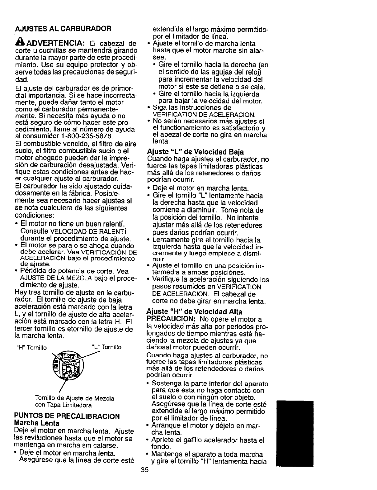
AJUSTES ALCARBURADOR
A(_ADVERTENCIA: El cabezal de
corte u cuchillas se mantendr& girando
durante la mayor parte de este procedi-
miento. Use su equipo protector y ob-
serve todas las precauciones de seguri-
dad.
El ajuste del carburador es de primor-
dial importancia. Si se hace incorrecta-
mente, puede daSar tanto el motor
corno el carburador permanente-
mente. Si necesita m&s ayuda o no
est_ seguro de c6mo hacer este pro-
cedimiento, Ilame al n6mero de ayuda
al consumidor 1-800-235-5878.
El combustible vencido, el filtro de aire
sucio, el filtro combustible sucio o el
motor ahogado pueden dar la impre-
sibn de carburacibn desajustada. Veri-
fique estas condiciones antes de hac-
er cualquier ajuste al carburador.
El carburador ha sido
• ajustado cuida-
dosamente en la fabrica. Posible-
mente sea necesario hacer ajustes si
se nota cualquiera de las siguientes
condiciones:
• El motor no tiene un buen ralentL
Consulte VELOCIDAD DE RALENT_
durante el procedimiento de ajuste.
• El motor se para o se ahoga cuando
debe acelerar, Vea VERIFICACION DE
ACELERACI(_N bajo el procedimiento
de ajuste.
• P_ridida de potencia de corte. Yea
AJUSTE DE LA MEZCLA bajo el proce-
dimiento de ajuste.
Hay tres tornillo de ajuste en le carbu-
rador. El tornillo de ajuste de baja
aceleraci6n est,. marcado con la letra
L, y el tornillo de ajuste de alta aceler-
aci6n est& marcado con la letra H. El
tercer tornillo es etornillo de ajuste de
la marcha lenta.
"H" Tornillo "L" Tornillo
Tomillo de Ajuste de Mezcla
con Tapa Limitadora
PUNTOS DE PRECALIBRACION
Marcha Lenta
Deje el motor en marcha lenta. Ajuste
las reviluciones hasta que el motor se
mantenga en marcha sin calarse.
• Deje el motor en marcha lenta.
Asegt_rese que la linea de corte est_
extendida el largo m_ximo permitido-
por el limitador de Ifnea'.
• Ajuste el tornillo de marcha lenta
hasta que el motor marche sin alar-
see.
• Gire el tornillo hacia la derecha (en
el sentido de las agujas del reloj)
para incrementar la velocidad del
motor si este se detiene o se cala.
• Gire el tornillo hacia la izquierda
para bajar la velocidad del motor.
• Siga las instrucciones de
VERIFICATION DE ACELERACION.
• No ser&n necesarios m&s ajustes si
el functionamiento es satisfactorio y
el abezal de corte no gira en marcha
lenta.
Ajuste "L" de Velocidad Baja
uando haga ajustes al carburador, no
fuerce, las,tapas limitadoras pl&sticas
mas alia de los retenedores o daSos
podrian ocurrir.
• Deje el motor en marcha lenta.
• Gire el tornillo "L" lentamente hacia
la derecha hasta que la velocidad
comiene a disminuir. Tome nota de
la posici6n del tornillo. No intente
ajustar m&s all_ de los retenedores
pues daSos podrlan ocurrir.
• Lentamente gire el tornillo hacia la
izquierda hasta que la velocidad in-
cremente y luego empiece a disrni-
nuir.
• Ajuste el tornillo en una posici6n in-
termedia a ambas posici6nes.
• Verifique la aceleraci6n siguiendo los
pasos resumidos en VERIFICATION
DE ACELERAClON. El cabezal de
corte no debe girar en marcha lenta.
Ajuste "H" de Velocidad Alta
PRECAUCION: No opere el motor a
la velocidad m&s alta por periodos pro-
Iongados de tiempo mientras est_ ha-
ciendo la mezcla de ajustes ya que
daSosal motor pueden ocurrir.
Cuando haga ajustes al carburador, no
fuerce las tapas lirnitadoras pl&sticas
m&s all& de los retendedores o daSos
podrfan ocurrir.
• Sostenga la parte inferior del aparato
para que esta no haga contacto con
el suelo o con ning6n otor objeto.
Aseg6rese que la linea de corte est_
extendida el largo mdximo permitido
pot el limitador de linea.
• Arranque el motor y d_jelo en mar-
cha lenta.
• Apriete el gatillo acelerador hasta el
fondo.
• Mantenga el aparato a toda marcha
y gire el tornillo "H" lentamenta hacia
35
la derecha hasta que la velocidad
aminore.
• No suelte el gatillo acelerador y gire
el tornillo hacia la izquierda hasta
que el motor comience a marchar
toscamente.
• Con el gatillo todavia a fondo, gire el
tornillo poci a poco hasta que el mo-
tor empiece a marchar suavemente.
• Verifique la aceleraci6n siguiendo los
pasos resumidos en VERIFICATION
DEACELERAClON. El cabezal de
corte no debe girar en marcha lenta.
Verificacibn de Aceleraci6n
• Deje el motor en marcha lenta.
Aseg_rese que la linea de corte est_
extendida el largo maxlmo permitido
Prepare el aparato para almacenarlo
por el limitador de linea.
• Apriete el gatillo a fondo. Si el motor
no acelera suavemente, gire el tornil-
Io "L" hacia la izquierda una pequeSa
cantidad (no m&s de el ancho de la
ranura del tornillo de ajuste). No in-
tente ajustar los tornillos m&s all& de
los retenedores ya que da_os
podrian ocurrir.
• Repita los pasos arriba menciona-
dos hasta que el motor acelere sua-
vemente. No intente ajustar el tornil-
Io m&s all& de los retenedores ya
que dar_os podrlan ocurrir.
TIEMPO DE IGNIQION
El tiempo de ignici6n es fijo e inalter-
able.
al final de la temporada o si no Io va a
usar por m&s de 30 dfas.
ADVERTENCIA:
• Permita que el motor se enfrie y fije
bien el aparato antes de guardarlo o
transportarlo.
• Guarde el aparato y el combustible
en un lugar bien ventilado donde los
vapores del combustible no puedan
entrar en contacto con chispas ni lla-
mas abiertas provenientes de clenta-
dores de agua, motores o interrpu-
tores el_ctricos, calefactores
centrales, etc.
• Guarde el aparato con todos los pro-
tectores en su lugar y coloquelo de
modo que las piezas cortantes no
puedan causar heridas por acci-
dente.
• Guarde el aparato y el combustible
en un lugar completamente fuera del
alcance de los niSos.
SUPERFICIES EXTERNAS
Siva a almacenar el aparato durante
un periodo largo de tiempo, Ifmpielo
rigurosamente antes de guardarlo. AI-
macene en un &tea limpia y seca.
• Aplique una pequeSa cantidad de
aceite alas superficies externas
met&licas.
SISTEMA DE COMBUSTIBLE
Vea el mensaje marcado como
IMPORTANTE, que se refiere al uso
de combustibles con mezcla de alco-
hol en su aparato, en la secci6n de
USO, bajo ABASTECIMIENTO DEL MO-
TOR. Los estabilizadores de combus-
tible son una alternativa aceptable
para minimizar la formaci6n de dep6si-
tos de goma durante el almacenaje.
Af}ada estabilizador a la gasolina en el
tanque de combustible o en el reci-
piente para almacenar el mismo. Siga
las instrucciones de mezcla que se en-
cuentran impresas en el envase. Pon-
ga el motor en marcha y d_jelo en
marcha por unos 5 minutos despu_s
de haberle puesto estabilizador.
El aceite Craftsman 40:1 para motores
a 2 tiempos (enfriados a aire) viene
mezclado con estabilizador de com-
bustible. Si no usa este aceite de
Sears, usted podr_, aSadir estabiliza-
dor al tanque de combustible.
INTERIOR DEL MOTOR
• Retire la buj(a y vierta una cucharad-
ira de aceite 40:1 para motores a 2
tiempos (enfriados a aire) por la ab-
ertura para la bujia. Lentamente, tire
de la cuerda de arranque de 8 a 10
veces para distribuir el aceite.
• Cambie la bujia por una nueva del
tipo y de la gama de calor recomen-
dados.
• Limpie el filtro de aire.
• Examine todo el aparato pa_'a verifi-
car que no haya tornillos, tuercas ni
pernos sueltos. Cambie todas la pie-
zas da_adas, quebradas o gasta-
das.
• AI principio de la pr6xima temporada,
use exclusivamente combustible
fresco con la proporci6n correcta de
gasolina a aceite.
OTROS
• No guarde la 9asolina de una tempo-
rada a la pr6xlma.
• Cambie el recipiente de gasolina si
se empieza a oxidar.
36
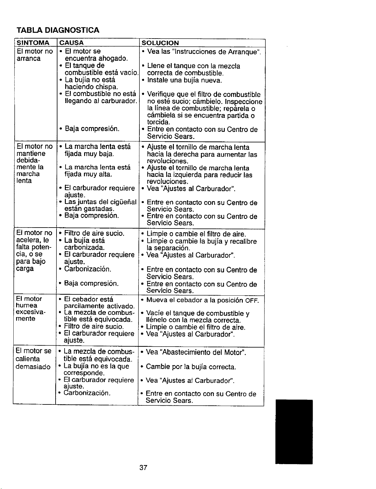
TABLA DIAGNOSTICA
SINTOMA
El motor no
arranca
El motor no
mantiene
debida-
mente la
marcha
lenta
El motor no
acelera, le
falta poten-
cia, o se
para bajo
carga
El motor
humea
excesiva-
mente
El motor se
calienta
demasiado
CAUSA
• El motor se
encuentra ahogado.
• El tanque de
combustible est& vac{o
• La bujia no est&
haciendo chispa.
• El combustible no est&
Ilegando al carburador.
• Baja compresibn.
• La marcha lenta est,,
fijada muy baja.
• La marcha lenta est,.
fijada muy alta.
• El carburador requiere
ajuste.
• Las juntas del cigOeSal
est&n gastadas.
• Baja compreslon.
• Filtro de aire sucio.
• La bujla est&
carbonizada.
• El carburador requiere
ajuste.
• Carbonizaci6n.
• Baja compresi6n.
• El cebador est&
parcilamente activado.
• La mezcla de combus-
tible est_l equivocada.
• Filtro de aire sucio.
• El carburador requiere
ajuste.
• La mezcla de combus-
tible estb equivocada.
• La bujfa no es la que
corresponde.
• El carburador requiere
ajuste.
• Carbonizaci6n.
:SOLUCION
• Vea las "lnstrucciones de Arranque".
• Llene el tanque con la mezcla
correcta de combustible.
• Instale una bujfa nueva.
• Verifique que el filtro de combustible
no est_ sucio; c&mbielo. Inspeccione
la linea de combustible; rep_rela o
c&mbiela si se encuentra partida o
torcida.
• Entre en contacto con su Centro de
Servicio Sears.
• Ajuste el tornillo de marcha lenta
hacia la derecha para aumentar las
revoluciones.
• Ajuste el tornillo de marcha lenta
hacia la izquierda para reducir las
revoluciones.
• Vea "Ajustes al Carburador".
• Entre en contacto con su Centro de
Servicio Sears.
• Entre en contacto con su Centro de
Servicio Sears.
• Limpie o cambie el filtro de aire.
• Limpie o cambie la bujfa y recalibre
la separaclon.
• Vea "Ajustes al Carburador".
• Entre en contacto con su Centro de
Servicio Sears.
• Entre en contacto con su Centro de
Servicio Sears.
• Mueva el cebador a la posici6n OFF.
• Vac{e el tanque de combustible y
II_nelo con la mezcla correcta.
• Umpie o cambie el filtro de aire.
• Vea "Ajustes al Carburador".
• Vea "Abastecimiento del Motor".
• Cambie por la bujia correcta.
• Vea "Ajustes at Carburador".
• Entre en contacto con su Centro de
Servicio Sears.
37

SUS DERECHOS Y OBLIGACIONES
DE GARANTIA: La Agencia de Pro-
tecci6n Ambiental de los Estados Uni-
dos, la Junta de Recursos Ambien-
tales de California y SEARS,
ROEBUCK AND CO., se compiacen
en explicarle la garantfa del sistema
de control de emisiones en el motor de
su equipo de jardin y c_sped. Todos
los motores de equipo utilitario, de
c_sped y jardfn nuevos deber&n ser
diseSados, construndos y equipados
para satisfacer las normas rigurosas
en contra de la contaminacibn del am-
biente. SEARS deber& garantizar el
sistema de control de emisi6n en el
motor del equipo de cesped y jardfn
por los periodos de tiempo enumera-
dos a continuaci6n, estipulando que
no haya habido ning_n tipo de abuso,
negligencia, o mantenimiento no apro-
piado del motor de su equipo de
c_sped y jardin. Su sistema de control
de emisi6n incluye piezas tales como
el carburador y el sistema de igniciSn.
Cuando existe una condicibn bajo ga-
rantia, SEARS reparar& el motor de su
equipo de c_sped y jard_n sin costo
atguno para usted. Los gastos cubier-
tos bajo garantfa incluyen diagnSstico,
piezas y servicio. CUBIERTA DE GA-
RANTIA DEL FABRICANTE: Si cual-
quier pieza relacionada con la emisi6n
en su motor (como se enumeran en la
Lista de Piezas de Control de Emisi6n
Bajo Garantla) se encontrara defec-
tuosa o un defecto en los materiales o
mano de obra del motor causara el
mal funcionamiento de tal pieza rela-
cionada con la emisiSn, esta pieza
ser& reparada o reemplazada por
SEARS. GARANTIA DE RESPONSA-
BILIDAD DEL DUEI_IO: Corno duefio
del equipo de c_sped y jardin, usted
es responsable del mantenimiento re-' '
querido indicado en el Manual del
Usuario. SEARS recomienda que
guarde todos los recibos que cubren el
mantenimiento de] motor de su equipo
de c_sped y jardln, pero SEARS no
puede negar la garantfa _nicamente
por la falta de recibos o por el incum-
plimiento de las indicaciones de rnan-
tenimiento. (.3orno duefio del motor del
equipo de c_sped y jardln, usted debe
saber que SEARS puede negarle la
cubierta de garantia si el motor de su
equipo de cesped y jard_n o una pieza
del mismo, ha fallado debido al abuso,
negligencia, mantenimiento no apro-
piado, modificaciones sin aprobaciSn,
o el uso de piezas que no han sido he-
chas o aprobadas por el fbricante orig-
inal del equipo. Usted ser& el respons-
able de pre-sentar el motor del equipo
de c_sped y jardin a un centro de re-
paraciones autorizado SEARS tan
pronto como surjaa el problema. Las
reparaciones bajo garantia deber&n
ser completadas en una cantidad ra-
zonable de tiempo, no excediendo los
30 dias. Si cuenta con alguna pregun-
ta en referencia a sus derechos y re-
sponsabitidades, usted deber& entrar
en contacto con su centro de servicio
autorizado m&s cercano o Ilamar a
SEARS al 1-800-473-7247. FECHA
DEL COMIENZO DE LA GARANTIA:
El periodo de garantia comienza en la
fecha en que se comprb el motor del
equipo de c_sped y jardfn. DURA-
CION DE LA GARANTIA: Esta ga-
rantfa tiene un periodo de cubierta de
dos ahos desde la fecha iniciat de
compra. QUE CUBRE: REPARA-
CLONES O REEMPLAZO DE PIEZAS.
Las reparaciones o reemptazo de cu-
alquier pieza en garantia ser&n efec-
tuadas sin cargo alguno para el duefio
en un centro de servicio SEARS apro-
bado. Si tiene alguna pregunta en rela-
ci6n con sus derechos y responsabili-
dades de garantia, usted deber&
comunicarse con su centro de servicio
autorizado m&s cercano o Ilamar a
SEARS al 1-800-473-7247. PERIODO
DE GARANTIA: Cualquier pieza bajo
garantia que no est_ programada para
ser reempiazada corno requisito del
pro_rarna de rnantenirniento, o la cual
este programada para set inspeccio-
nada de forma regular para efectos de
"reparaciones o reemplazos s] es ne-
cesario" deber_ garantizarse por dos
aSos. Cualquier pieza garantizada
que est_ programada para ser reem-
plazada como Io es requerido por el
programa de mantenimiento, deber&
ser garantizada por el periodo de tiem-
po hasta el primer carnbio programado
para el reemplazo. DIAGNOSTICO:
No se deber&cargar al duello ningt3n
tipo de recargos por el servicio de
diagnSstico el cual nos conduce a la
determinaci6n de que una pieza bajo
garantia est& defectuosa, si el trabajo
38

de diagn6stico ha sido Ilevado a cabo
en un centre de servicio SEARS apro-
bado. DANOS POR CONSECUEN-
ClAMAGES: SEARS puede ser re-
sponsable por daSos a otros
componentes del motor causados por
el fallo de una pieza garantizada rnien-
tras 6sta se encuentre en garantfa.
QUE NO CUBRE: Todos los fallos
causados pot el abuso, la negligencia,
o el mantenimiento no apropiado no
est&n cubiertos. PIEZAS PARA ANA-
DIR O MODIFICADAS: El uso de pie-
zas afiadidas o rnodificadas puede ser
la base para anular la garant{a.
SEARS no se hace responsable de
cubrir fallos de piezas garantizadas
debido al uso de piezas aSadidas o
modificadas. COMO ENTABLAR
UNA RECLAMACION: Si cuenta
usted con alguna pregunta en referen-
cia a sus derechos y responsabili-
dades de garantfa, usted deber& con-
tactar a su centro de servicio
autorizado mds cercano o Ilamar a
SEARS al 1-800-473-7247. EN
DONDE OBTENER SERVICIO DE
GARANTIA: Servicio o reparaciones
de garanfia deber& set provistas por
todos los centros de servicio SEARS,
Ilarne al: 1-800-473-7247. MANTENIMI-
ENTO, REEMPLAZO Y REPARA-
CLONES DE PIEZAS RELACIONADAS
CON LA EMISION: Cualquier pieza de
reemplazo SEARS aprobada usada en
la prograrnaci6n de cualquier.manten-
irniento de garantia o reparacaon de
piezas relacionadas con la emisi6n
ser& provista al duefio sin cargo algu-
no si la pieza se encuentra bajo ga-
rant{a. LISTA DE PIEZAS DE CON-
TROL DE EMISION BAJO
GARANTIA: Carburador, Sistema de
Ignici6n: Bujia (cubierta t_nicamente
hasta el periodo del primer rnantenirni-
ento programado), M6dulo de Ignici6n.
DECLARACION DE MANTENIMIEN-
TO: El dueSo es responsable de efec-
tuar todo mantenirniento prograrnado
corno lo define el Manual del Usuario.
39

For in-home major brand repair service:
Call 24 hours a day, 7 days a week
1-800-4-MY-HOMETM
(1-800-469-4663)
Para peflir servicio de reparaci6n a domicilio -- 1-800-676-5811
In Canada for all your service and parts needs call
Au Canada pour tout le service ou les pi_ces -- 1-800-665-4455
For the repair or replacement parts you need:
Calf 6 am - 11 pm CST, 7 days a week
PartsDirect TM
1-800-366-PART (1-800-366-7278)
Para ordenar piezas con entrega a domicilio -- 1-800-659-7084
For the location of a Sears Parts and Repair Center in your area:
Call 24 hours a day, 7 days a week
1-800-488-1222
For information on purchasing a Sears Maintenance Agreement
or to inquire about an existing Agreement:
Call 9 am - 5 pm, Monday - Saturday
1-800-827-6655
SEARS
HomeCentraF