Loading ...
Loading ...
Loading ...
ASSEMBLY
I I iii
BRUSHWACKER CONFIGURATION
Assembly information for Weedwacker configuration is
located before this section, the Brush Blade configura-
tion follows after thissection.
DANGER:
THE METAL SHIELD MUST BE PROPERLY
INSTALLED ON THE TOOL ANYTIME THE
TOOL IS USED WITH THE BLADE. THE
FORWARD TIP ON THE METAL SHIELD
HELPS TO REDUCE THE OCCURRENCEOF
BLADE THRUST WHICH CAN CAUSE
SERIOUS INJURY SUCHAS AMPUTATION
TOTHEOPERATORORBYSTANDERS.
FAILURETO INSTALLTHE DEBRIS SHIELD
IN THE POSITION SHOWNCAN RESULT IN
SERIOUSINJURYTO THE OPERATOR.THE
LENGTHOF THE DEBRISSHIELD MUST BE
ALIGNEDWRH THE LENGTHOF THE DRIVE
SHAFTHOUSING.
THE BLADEIS SHARPANDCAN CUT YOU.
BE SURE TO WEAR GLOVES WHILE
WORKING WITH BLADES
METAL DEBRIS SHIELD ASSEMBLY (Fig. 7)
NOTE: If your unitis equippedas a line trimmer,remove
the semi-automatic head, grass washer, and plastic
debris shield.Storepartsfor future use.
• Remove and discardthe packingcoverfrom the arbor
shaft, if so equipped_
• Remove the dustcup.Save for later use.
• Position the retention plate on the underside of the
metal debris shield and align screwholes. Make sure
the flat side of the plate is against the metal debris
shield.
• Hold the retentionplate in positionand place the metal
debrisshield underthegear box.Alignscrewholes.
• Insertthe four metaldebdsshield screwsone at a time
through the gear box and debris shield, then thread
them intothe retentionplate,
• Tighten the debris shield screwsevenly and securely
with the long hex key (provided),
HEX
_'q_ SCREW KEY
GEAR
_I_'_DUST CUP
i I _-*" ARBOR
METAL I SHAFT
SHIELD _
RETENTION
PLATE
ii ii i iiiiIIIH
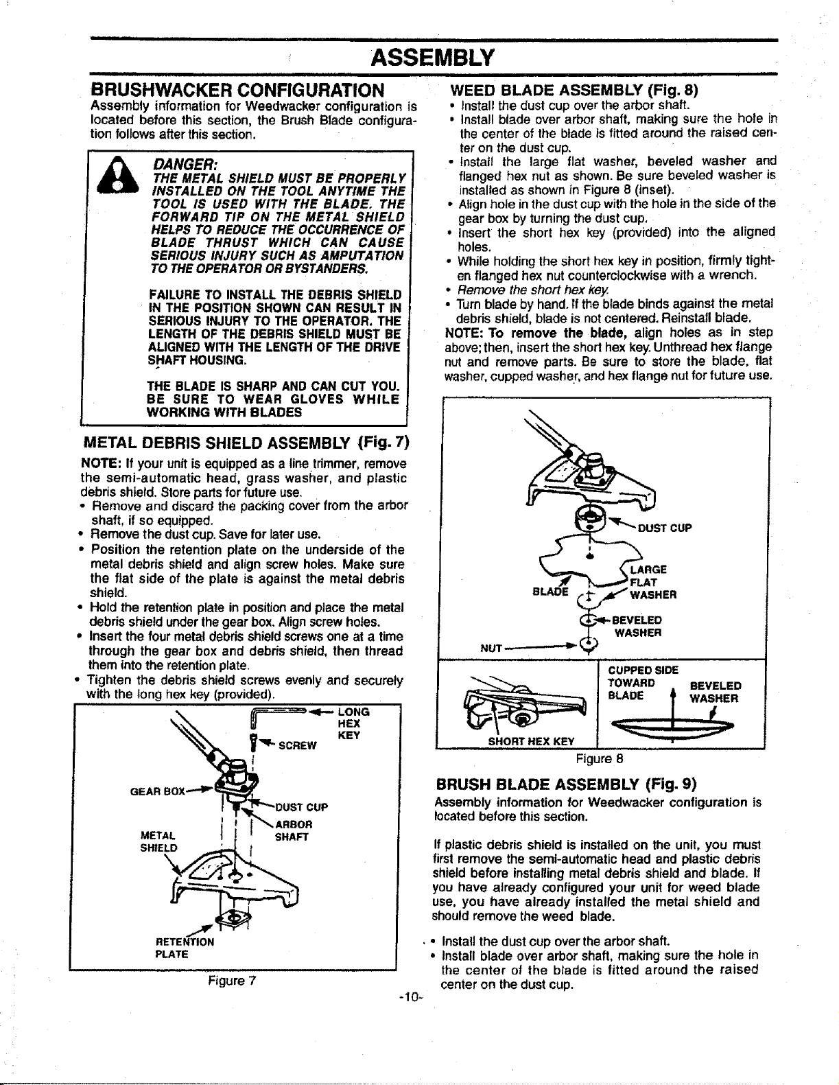
WEED BLADE ASSEMBLY (Fig. 8)
• Installthe dust cup overthe arbor shaft.
• Install blade over arbor shaft, making sure the hole in
the center of the blade is fitted around the raised cen-
ter on the dust cup.
• Install the large flat washer, beveled washer and
flanged hex nut as shown. Be sure beveled washer is
installed as shown in Figure 8 (inset).
• Align hole in the dust cupwith the holein the side of the
gear box by turningthe dust cup.
• insert the short hex key (provided) into the aligned
holes.
• While holding the short hex key in position, firmly tight-
en flanged hex nutcounterclockwisewith a wrench.
• Remove the short hex key.
• Turnblade by hand. ft the blade binds against the metal
debris shield, blade is not centered. Reinstall blade.
NOTE: To remove the blade, align holes as in step
above;then, insert the short hex key.Unthread hex flange
nut and remove parts. Be sure to store the blade, flat
washer,cupped washer, and hex flange nutfor future use.
T CUP
%LARGE
_.. _ __ FLAT
BLADE _ _4_I"WASHER
_1- BEVELED
(_";) WASHER
NUT-- _ _
Ji _ i,J , . L,. LI
CUPPED SIDE
SHORT HEX KEY
TOWARD BEVELED
Figure 8
BRUSH BLADE ASSEMBLY (Fig. 9)
Assembly informationfor Weedwacker configuration is
locatedbeforethis section.
If plastic debris shield is installedon the unit, you must
first remove the semi-automatic head and plastic debris
shield before installing metal debris shield and blade. If
you have already configured your unit for weed blade
use, you have already installed the metal shield and
should remove the weed blade.
• Installthe dust cup overthe arbor shaft.
, Install blade over arbor shaft, making sure the hole in
the center of the blade is fitted around the raised
center on the dust cup.
Figure 7
-10-
Loading ...
Loading ...
Loading ...