Loading ...
Loading ...
Loading ...
ASSEMBLY
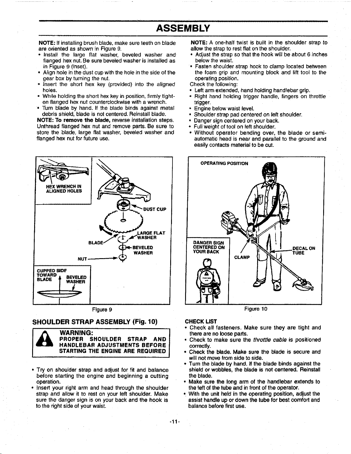
NOTE: If installing brush blade, make sure teeth on blade
are oriented as shownin Figure 9.
• Instal_ the large flat washer, beveled washer and
flanged hex nut. Be sure beveled washer is instaiJed as
in Figure 9 (inset).
• Aiign hole inthe dust cup with the hole in the side of the
gear box by turning the nut.
° Insert the short hex key (provided) into the aligned
holes,
• While holding the short hex key in position,firmIy tight-
en flanged hex nut counterclockwise with a wrench.
° Turn blade by hand. If the blade binds against metal
debris shield, blade is not centered. Reinstall blade.
NOTE: To remove the blade, reverse installation steps.
Unthread flanged hex nut and remove parts.Be sure to
store the blade, large flat washer, beveled washer and
flanged hex nut for future use,
NOTE: A one-half twist is built in the shoulder strap to
allow the strap to rest flat on the shoulder.
° Adjust the strap so that the hook wilt be about 6 inches
below the waist.
• Fasten shoulder strap hook to clamp located between
the foam grip and mounting block and lift tool to the
operating position.
Check thefollowing:
• Left arm extended, hand holding handlebar grip.
• Right hand holding trigger handle, fingers on throttle
trigger.
• Engine below waist tevel.
• Shoulder strap pad centered on left shoulder.
• Danger sign centered on your back.
• Fullweight of tool on leftshoulder.
• Without operator bending over, the blade or semi-
automatic head is near and parallel to the ground and
easily contacts material to be cut.
HEX WRENCH IN
ALIGNED HOLES
VASHER
NUT _-
WASHER
CUPPED SIDE
TOWARD
==1An= _ BEVELED
ii i
Figure 9
SHOULDER STRAP ASSEMBLY (Fig. 10)
I_ WARNING: J
PROPER SHOULDER STRAP AND 1
HANDLEBAR ADJUSTMENTS BEFORE !
STARTING THE ENGINE ARE REQUIRED J
• Try on shoulder strap and adjust for fit and balance
before starting the engine and beginning a cutting
operation.
• Insert your right arm and head through the shoulder
strap and allow it to reston your left shoulder. Make
sure the danger sign is on your back and the hook is
to the rightsideof your waist.
OPERATING POSITroN
DANGER SIGN
CENTERED ON
YOUR BACK
CLAMP
DECALON
Figure 10
CHECK LIST
• Check all fasteners. Make sure they are tight and
there are no loosepads.
• Check to make sure the throttle cable is positioned
correctly.
° Check the blade. Make sure the blade is secure and
willnot movefromside to side.
° Turn the blade by hand. if the blade binds againstthe
shield or wobbles,the blade is not centered. Reinstall
the blade.
° Make sure the long arm of the handlebar extends to
the left of the tube and in front of the operator.
• With the unit held in the operating position, adjust the
assisthandle up or down the tube for best comfort and
balance before first use.
-11-
Loading ...
Loading ...
Loading ...