Loading ...
Loading ...
Loading ...
WARNING: CONNECTOR BLOCK IS APPROVED
FOR COPPER WIRE CONNECTION ONLY.
2. Aluminum Wiring
A. Connect length of copper building wire to range ter-
minal block,
B. Splice copper wires to aluminum wiring using
special connectors designed and UoL. approved for
joining copper to aluminum, and follow the connector
manufacturer's recommended procedure closely.
NOTE: Wire used, location and enclosure of splices,
etc., must conform to good wiring practice and local
codes.
5
Speciaa Grounding instructions
WARNING:
1. If local codes do not permit
grounding through neutral,
disconnect the strap, located at
the bottom of connector block,
from the frame and cut off to pre-
vent contact with the range body.
To ground range frame, a 4th
grounding lead must be con-
nected to range frame in accord-
ance with local codes, using only
ground lug and screw°
_,UG
2. Mobile Home Installation--If this range is provided
with a 3-conductor cord or cable assembly, or if local
codes do not permit grounding through the neutral, the
grounding strap must be removed and the 3-conductor
cord or cable assembly must be replaced by a
4-conductor cord as follows:
A. Remove the 3-conductor cord by removing the strain
relief and terminal lugs from the connector block.
B. Attach the 4-conductor cord as described in STEP
5.1, except attach 4th wire to previous location of the
grounding strap.
6
Anti-Tip Bracket
Hnstallation
An ANTI-TIP bracket is
supplied with instruc-
tions for installation in a
variety of locations. The
instructions include a
template, a parts list and
• .F_ _ . ..... -_j:_'.t..
Bracket Installation Tempiate
a list of tools necessary to complete the installation.
Read the IMPORTANT SAFETY INSTRUCTIONS and
the instructions that fit your situation before beginning
installation.
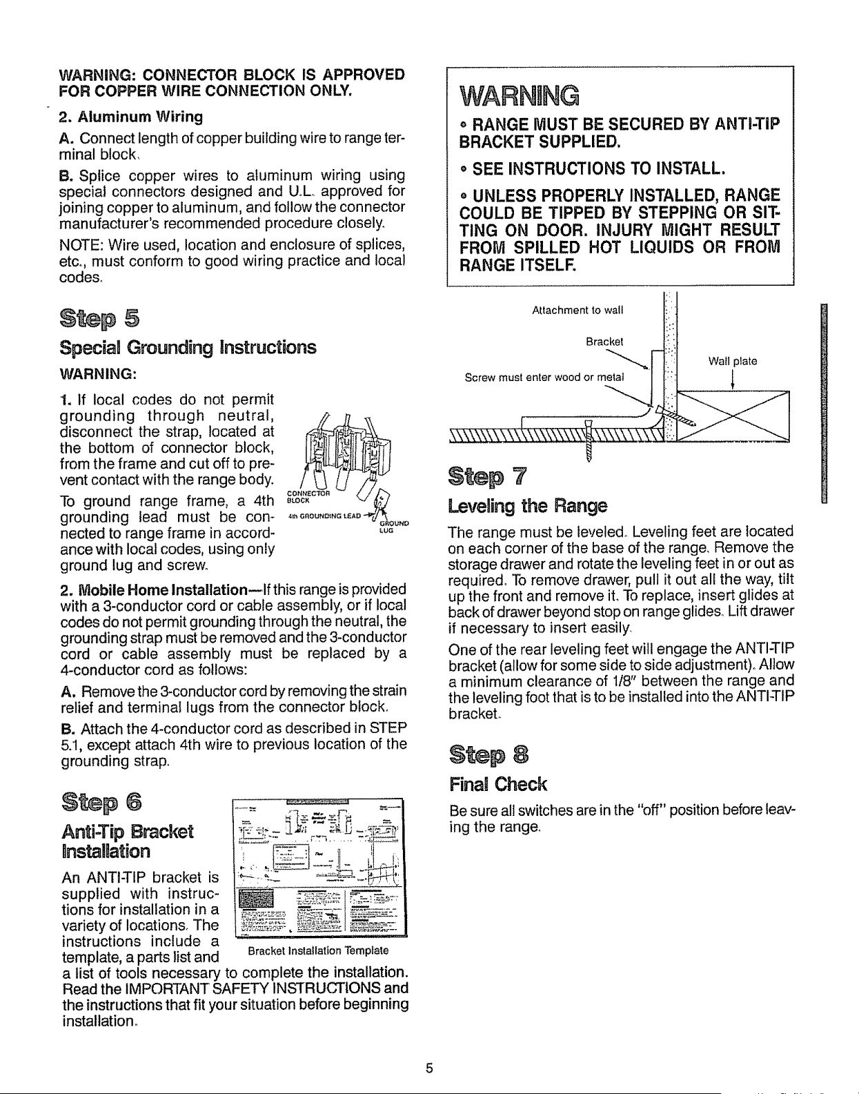
WARNmNG
° RANGE MUST BE SECURED BY ANTI-TIP
BRACKET SUPPLIED.
o SEE INSTRUCTIONS TO INSTALL.
° UNLESS PROPERLY INSTALLED, RANGE
COULD BE TIPPED BY STEPPING OR SIT-
TING ON DOOR. INJURY MIGHT RESULT
FROM SPILLED HOT LIQUIDS OR FROM
RANGE ITSELF.
Attachment to wail
Bracket
Screw must enter wood or metal
Wail prate
t
Leveling the Range
The range must be leveled_ Leveling feet are located
on each corner of the base of the range. Remove the
storage drawer and rotate the leveling feet in or out as
require& To remove drawer, pull it out all the way, tilt
up the front and remove it. To replace, insert glides at
back of drawer beyond stop on range glide& Lift drawer
if necessary to insert easily.
One of the rear leveling feet will engage the ANTI-TIP
bracket (allow for some side to side adjustment)° Allow
a minimum clearance of 1/8" between the range and
the leveling foot that is to be installed into the ANTI-TIP
brackeL
Fina! Check
Be sure all switches are in the "off" position before leav-
ing the range_
5
Loading ...
Loading ...
Loading ...