Loading ...
Loading ...
MNSTALLATIONHNSTFIUC3:aON$
JMPOFtTANT:SAVE FOR THE LOCAL ELECTRICAL iNSPECTOR'S USE
Electrical Requirements
CAUTION, FOR PERSONAL SAFETY:
DO NOT USE AN EXTENSION CORD WITH THIS
APPLIANCE.
REMOVE HOUSE FUSE OR OPEN CIRCUIT
BREAKER BEFORE BEGINNING INSTALLATION,
This appliance must be supplied with the proper
voltage and frequency, and connected to an individual
properly grounded branch circuit, protected by a cir-
cuit breaker or time delay fuse, as noted on the rating
plate (Rating plate is located on door frame,)
Wiring must conform to National Electric Codes.
If the electric service provided does not meet the above
specifications, it is recommended that a licensed elec-
trician install an approved outlet.
Because range terminals are not accessible after range
is in position, use flexible service conduit or cord.
$lie :1
Prepare the Opening
11/2" spacing is recommended from the range to adja-
cent vertical walls above the cooktop surface.
Allow 30" minimum clearance between surface units
and bottom of unprotected wood or metal top cabinet,
and t5" minimum between countertop and adjacent
cabinet bottom°
Your range, like many other household items, is
heavy and can settle into soft floor coverings such
as cushioned vinyl or carpeting. When moving the
range on this type of flooring, use care, and it is recom-
mended that these simple and inexpensive instructions
be followe&
The range should be installed on a sheet of plywood
(or similar material) as follows: When the floor cover.
ing ends at the front of the range, the area that the
range will rest on should be built up with plywood to
the same level or higher than the floor covering. This
will allow range to be moved for cleaning or servicing.
$tl!!p 2
Prepare for Electricaa Connection
Use a 3-conductor, or if required, a 4-conductor range
cord set as noted below,.
For Ranges Less than or Equal to 12.1 KW
9-5255 3 condo 4' 50A-125!250V
9-5237 4 cond. 4' 50A-125/250V
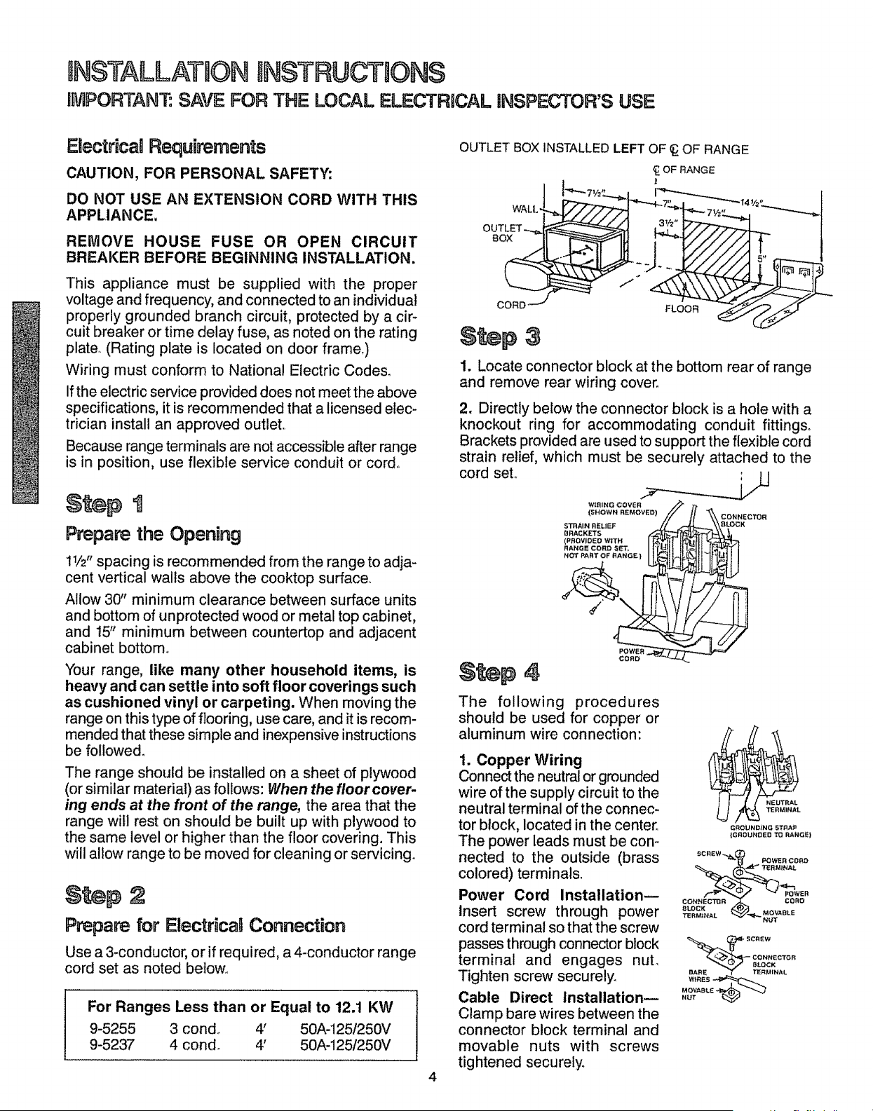
OUTLET BOX INSTALLED LEFT OF _ OF RANGE
1_OF RANGE
CORD _
$ttep
1. Locate connector block at the bottom rear of range
and remove rear wiring coven
2, Directly below the connector block is a hole with a
knockout ring for accommodating conduit fittings°
Brackets provided are used to support the flexible cord
strain relief, which must be securely attached to the
cord set.
WIRING (3OVER _ r,
STRAIN RELIEF // _ \,_\a_C K
(PROVlOEOW:TH 6"_11(I_(ll
RANGEconoSET, rr_lt II I_ilt.JlL4f_rTI
NOT PART OF RANGE} 1tt'-4.II_il<'><_tlIHNJ I I
The following procedures
should be used for copper or
aluminum wire connection:
1. Copper Wiring
Connect the neutral or grounded
wire of the supply circuit to the
neutral terminal of the connec-
tor block, located in the center_
The power leads must be con-
nected to the outside (brass
colored) terminals.
Power Cord Installation--
Insert screw through power
cord terminal so that the screw
passes through connector block
terminal and engages nuL
Tighten screw securely.
Cable Direct Installation--
Clamp bare wires between the
connector block terminal and
movable nuts with screws
tightened securely°
NEUTRAL
_TERMINAL
GROUNDING STRAP
{GROUNDED TO RANGE)
_ POWER CORO
COt_NECTOR ._ CORD
_LOCK
CREW
CONNECTOR
BARE _r TERMINAL
WIRESr: _
MOVA8_.
NUT
Loading ...
Loading ...
Loading ...