Loading ...
Loading ...
Loading ...
10
The control panel MUST remain removable for servicing
(see PARTS LIST).
THIS UNIT MUST NOT BE LOCATED IN A FULLY
ENCLOSED AREA OF ANY KIND.
ENSURE PROPER COMBUSTION AIR AND
COOLING AIRFLOW
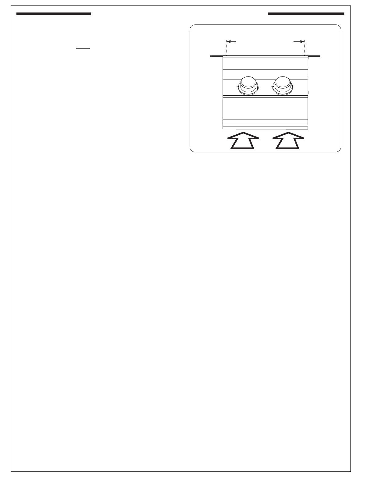
Proper airfl ow (Fig. 10-1) MUST be maintained for the
sideburner to perform as it was designed. If airfl ow is
blocked, overheating and poor combustion will result.
Do not block the 1" front air inlet along the bottom of
the control panel or more than 75% of the cooking grid
surface with pans or griddles.
GAS-SUPPLY PLUMBING REQUIREMENTS
For natural gas or a household propane system, rigid
1
/
2
" or
3
/
4
" black steel pipe or local code-approved
pipe is required to conduct the gas supply to the unit.
Contact your local gas supplier. Connect this pipe to a
required C.S.A.-approved stainless-steel fl ex connector
(attached). An NPT adapter has been provided for
1
/
2
"
pipe. DO NOT use a rubber hose within the unit
enclosure. Apply only joint compounds that are resistant
to all gasses to all male pipe fi ttings except fl are fi ttings.
Make sure to tighten every joint securely.
Note: If
1
/
2
" pipe is used with natural gas, it should
be no longer than 20'.
Important: A shut-off valve (not included) in
the gas line is required. It provides
for safety when the unit is not in use
and for convenient maintenance and
repair. It must be installed within 6 feet
of the unit. Use a pipe joint compound
resistant to all gasses on all male
fi ttings except fl are fi ttings.
GAS SUPPLY AND MANIFOLD PRESSURES:
For natural gas - normal 7" (17.78 cm) water column
(w.c.), minimum 5" (12.7 cm), maximum 10
1
/
2
" (26.7
cm). For propane gas - normal 11" w.c., minimum 10"
(25.4 cm), maximum 13" (33 cm).
INSTALLATION REQUIREMENTS (cont.)
REV 0 - 1601191055
L-C2-448
Fig. 10-1 Ventilation Diagram
DO NOT BLOCK
MORE THAN 75% OF
COOKING AREA
Loading ...
Loading ...
Loading ...