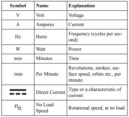
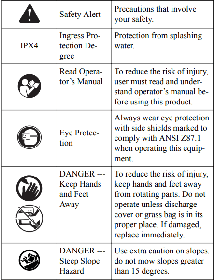
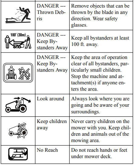
Some of the following symbols may be used on this tool.
Please study them and learn their meaning. Proper interpretation of these symbols will allow you to operate the tool better and safer.
DESCRIPTION
PURPOSE
This machine is used for domestic lawn mowing. The cutting blade should be parallel to the ground. All four wheels must touch the ground while mowing.
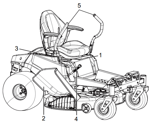
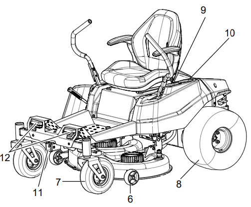
OVERVIEW
1. Seat adjustment lever 2. Side discharge chute 3. Control panel 4. Deck height adjustment lever 5. Steer control lever 6. Anti-scalp wheels 7. Front wheels 8. Rear wheels 9. USB port 10. Cup holder 11. ETO socket (2" X 2") 12. Headlight
KNOW YOUR MACHINE
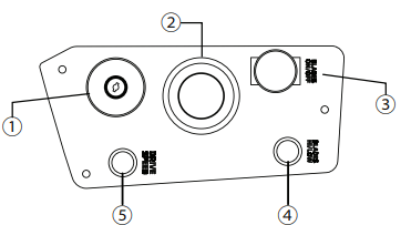
CONTROL PANEL
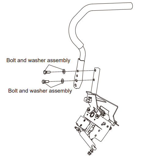
INSTALL THE ROLL OVER PROTECTION STRUCTURE (ROPS)
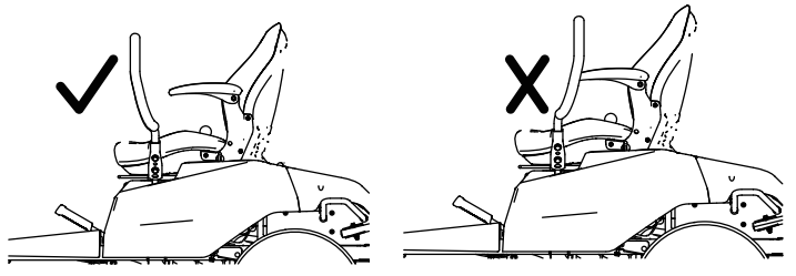
WARNING: The left and right steering levers should be adjusted so that they align with each other when in the neutral position. NEVER install the steering levers in an asymmetrical operating height.
#
Name
Function
1
Power switch with start key
The power switch is used to turn the mower on and off. The start key must be inserted before the switch can be operated
2
Digital display
This display shows important electrical system information. Refer to the Electrical section for complete information.
3
ON/OFF for blade (PTO)
Pull the PTO switch up to activate the mower’s cutting blades. Push the knob down to stop the cutting blades.
4
High/Low for blade speed
High blade mode is a higher blade speed for cutting thicker grass, while low blade mode provides lower blade speed for lower battery consumption on thinner, drier grass areas. Press it for high blade speed, the green light will be on. Pull it for low blade speed, the light will be off.
NOTE
Mowing time will be increased when mowing in low blade mode.
5
High/Low for driving speed
Allows operators to select a comfortable driving speed. Pressing it to “High Speed” position means that the maximum drive speed will be 8 mph, the green light will be on. Pull up it to “Low Speed” position means that the maximum drive speed will be 4 mph, the light will be off. Pull it up to “Low Speed” position for inexperienced operators or when trimming around objects, buildings and other obstacles.
NOTE: Get comfortable with mower before using “High Speed” setting. The maximum speed may be adjusted at any time, whether the mower is in motion or not.
INSTALL THE ROLL OVER PROTECTION STRUCTURE (ROPS)
Lift one steering lever to align the holes in the steering lever with the holes in the corresponding mounting pole. Select the preferred steering-lever operating height, and then use the wrench (13*16mm) to secure the steering lever as indicated below.
Assemble the other steering lever and in the same way
CAUTION: Do not install the upper handle reversely.
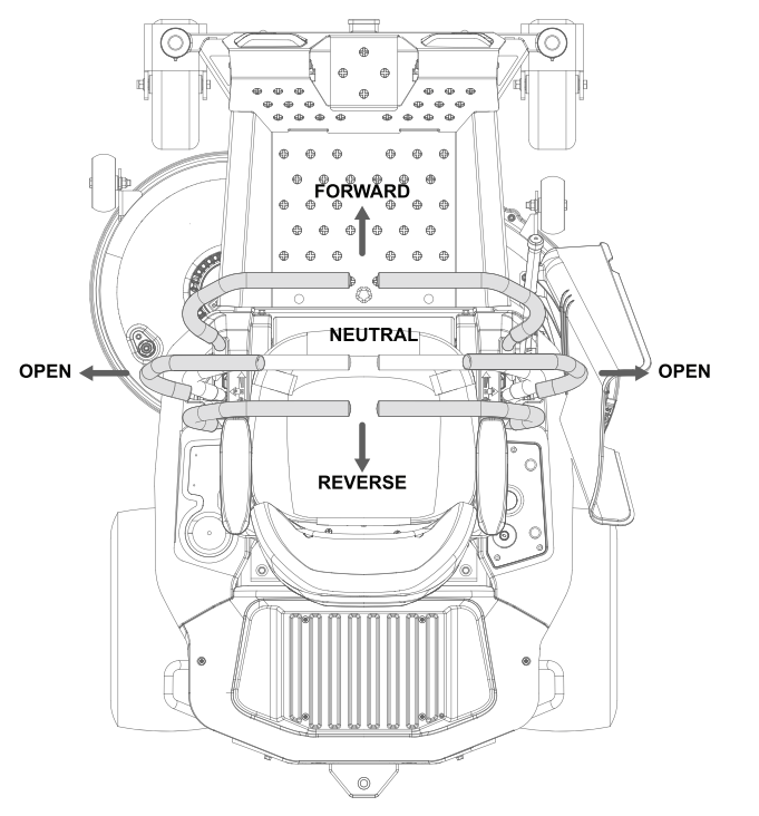
STEERING CONTROL LEVERS
The two levers control the mower’s speed, direction, stopping, neutral lock, and parking brake. Levers are used to steer, accelerate, decelerate, stop, and change direction. When the control levers are in the park brake position, the mower will not move.
ANTI-SCALP WHEELS
Anti-scalp wheel kits are standard on Greenworks Commercial units. These anti-scalp wheels (23) are designed to minimize scalping when mowing on rough, uneven terrain. After setting the cutting height, adjust the anti-scalp wheels so they extend below the deck but do not contact the ground. They should always be at least 1/4" to 3/4" below the deck. With the unit sitting on a flat level surface, the wheel position can be adjusted up or down as needed from 3/4" to 1-3/4" below the blade surface. Move the wheels up or down - using the different axle mount holes in the wheel mount bracket (if applicable on model).
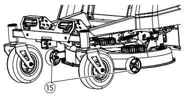
NEUTRAL BYPASS KNOB
Pull the neutral bypass knobs outwards and then downwards to unlock the wheel.
Move the neutral bypass knobs back into position to lock the wheels.
WARNING: Never drive mower with the neutral bypass knob working. Always install the neutral bypass knob to the original position before driving! Failure to re-install the knob could cause serious damage to your mower and void mower warranty!
WARNING: Never drive mower with the neutral bypass knob working. Always install the neutral bypass knob to the original position before driving! Failure to re-install the knob could cause serious damage to your mower and void mower warranty!
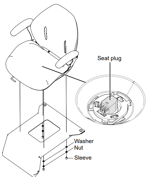
INSTALL THE SEAT
Place the seat assembly over the mounting brackets and align holes as shown.
Connect the seat plug to the machine. 10 EN English
Install the washers and nuts and tighten securely.
Attach the sleeve to the nut.
Make sure it is securely seated.
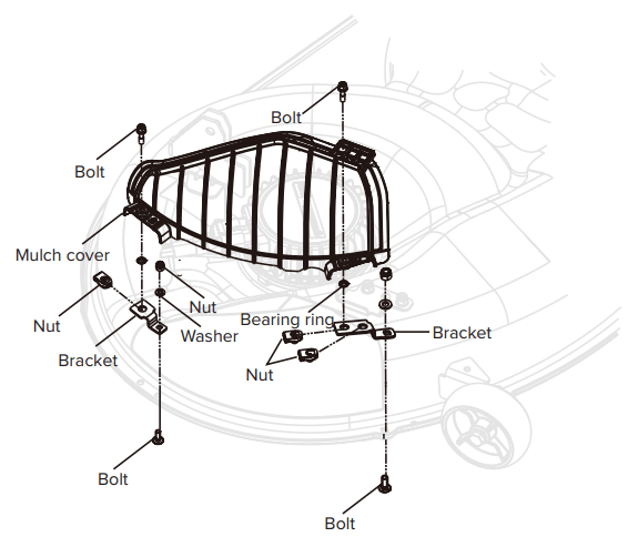
INSTALL THE ACCESSORIES
1. Mulch cover
INSTALL THE MULCH COVER
The mower is configured for side discharge when shipped. If mulching is desired:
Place the mulch cover on the tab on the mower housing.
Align the holes in the mulch cover and the holes in the mower housing.
Install and tighten the bolts, screws, fixation clamps and bearing ring as shown.
OPERATION
WARNING: Wear eye protection during operation.
BEFORE OPERATION
ADJUST THE SEAT
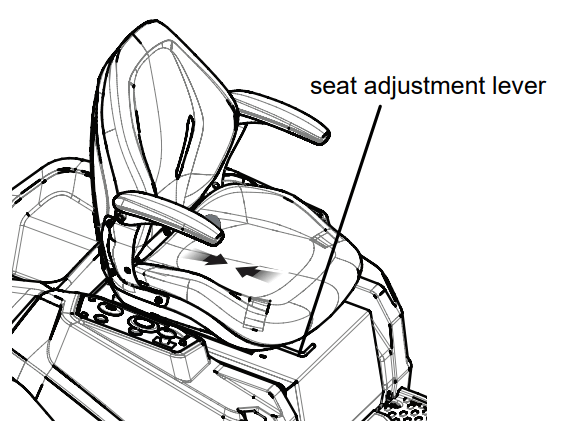
Push steer control levers outward into PARK BRAKE position before you adjust the seat.
Sit down on seat and lift the seat adjustment lever.
While holding the lever, slide the seat to the desired position.
Release the lever and make sure the seat is locked in position before operating the mower.
WARNING:Be sure the seat is locked into place before operating the mower. A seat that is not secure can cause the operator to shift and lose control of the mower and result in possible death or serious personal injury.
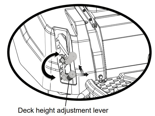
ADJUST THE DECK CUTTING HEIGHT
Before using the mower, raise the deck height to the cutting position best suited for your lawn.
Deck height is adjustable from 1.5-4.5" inches. Deck should be raised while mowing is in progress to avoid stumps, rocks or other obstacle that can be damage mower deck.
Stop the mower and disengage blades.
Turn key to OFF position and set the parking brake.
To raise the cutting deck, grasp the deck height adjustment lever, push left to disengage from slot, move toward the back of the mower, then push right into slot to secure.
To lower the cutting deck, grasp the deck height adjustment lever, push left to disengage from slot, move toward the front of the mower, then push right into slot to secure.
CAUTION: Hold the deck height adjustment lever firmly when setting the deck height and only release when it is secure in the desired slot. Quickly letting go of the lever may create a pinching or pulling hazard to the operator’s hand.
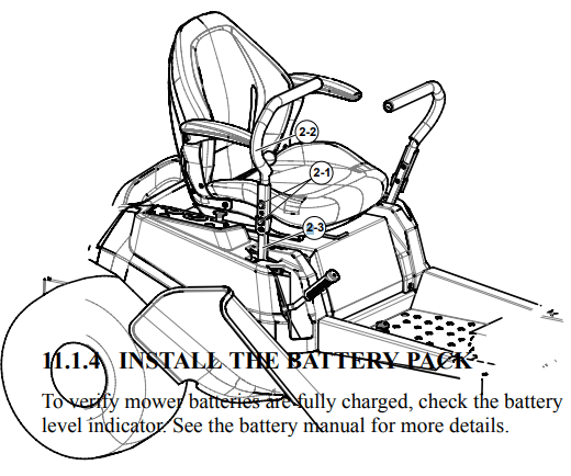
ADJUST THE STEERING CONTROL LEVER
The steering control levers (2) can be adjusted for operator comfort. By loosening the cap screws (2-1) that attaches the upper control lever (2-2) to the lower lever (2-3), the upper control lever can be pivoted to fit the operator’s personal preference. The steering control levers should be adjusted so that they align with each other when in the neutral position.
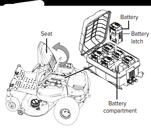
INSTALL THE BATTERY PACK
To verify mower batteries are fully charged, check the battery level indicator. See the battery manual for more details.
Lift the seat panel.
Lift the battery compartment cover.
Install the battery pack into the battery compartment.
WARNING: Align the ribs of the battery with the battery port. Make sure that the battery latch clicks into the battery compartment smoothly.
BEFORE OPERATING THE MACHINE
Ensure work area is clear of children, bystanders, and pets.
Clear the work area of objects that may be thrown by the mower blades.
Check brake operation.
Check tire pressure.
Check for loose fasteners.
Check to make sure all guards are in place and working properly.
Clean debris from mower.
Test safety interlock system.
Adjust seat to desired position.
Verify battery charge level.
SAFETY START INTERLOCK SYSTEM
The machine is equipped with a safety start interlock system consisting of the park brake switches, seat switch, and deck blades ON and OFF switch.
The mower’s safety start interlock system is also designed to protect the operator and others from accidental injury due to unintentional traction drive system starting.
Check mower safety start interlock system daily, prior to operation. This system is an important mower safety feature. It should be repaired immediately if it malfunctions. The machine incorporates a separate seat switch which will stop the drive system and deck motors when the operator is unseated for any reason while the mower is operating. This is a safety feature designed to prevent runaway or accidental entanglement.
WARNING:
The safety interlock system must not be disconnected or bypassed. Doing so could cause the machine to operate unexpectedly, resulting in personal injury.
To inspect the system:
1. The operator must be on the seat when testing the seat switch.
2. Turn the key to start the machine.
3. Pull the steering control levers to the parking slots.
4. Pull up on the PTO switch to engage the motor.
5. Slowly raise off of the seat. The deck blade system should stop.
6. If the deck blade system fails to stop when the operator is off of the seat and if the cause cannot be determined, contact your Greenworks dealer immediately.
OPERATE THE MACHINE
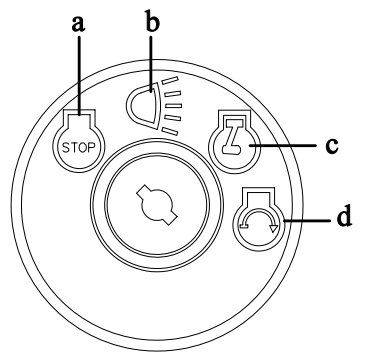
START THE MACHINE
WARNING: Clear the area of bystanders before operating the mower. If anyone enters the mowing area, stop immediately and do not return to mowing until the bystanders leave the area.
a
Stop / Off
b
On (with lights)
c
Run
d
Start
Raise the mower deck to its highest position.
Insert start key and turn to start position (d). NOTE: The buzzer alarms for one time, the machine is READY TO GO, then you can drive the machine even without blade working.
Release the parking brake NOTE: The key will return back to (c) position automatically. Wait for 4 seconds until the display shows normally.
Place steering control levers in forward (F) position and drive to desired mowing location.
NOTE: Turn the headlight on by turning the key to the postion (b) when you power on the machine.
WARNING: Use caution when crossing over gravel paths or driveways. Before crossing, disengage the blades and raise the cutting deck to the highest position to minimize the possibility of ricochet. Drive slowly to avoid loss of traction and control.
NOTE: Do not attempt to change the direction of operation while the mower is in motion. Always come to a complete stop before changing the mower direction.
WARNING: Steering control levers will spring back towards neutral position if you release them, but you still need to control them manually to reach neutral position.
STOP THE MACHINE
DANGER: Never make sudden stops or reverse direction, especially when maneuvering on a slope. The steering is designed for sensitive response. Rapid movement of the steering control levers in either direction could result in a reaction of the machine that can cause serious injury.
Return drive control levers to the Neutral position. Push drive control levers outward into park brake position.
Push down on the PTO switch to turn blades off.
Turn the key to OFF position (a).
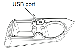
USE THE USB PORT
The USB charging port provides charging power of 5 Volts DC at up to 2.1 amps for your cell phone, MP3 player, or other USB devices. Consult the owner’s manual for your device for specific charging requirements.
Connect one end of a USB cable (not provided) to your device and the other end to the USB charging port on the mower, to begin charging your device.
NOTE:Attempting to charge devices rated more than 2.1 amps could damage the USB charging port and/or the mower.
NOTE: The USB port is only powered when the machine starts.
WARNING:
Never use headphones or any electronic device, such as a smart phone or tablet, while operating the mower. Distracted operation can result in an accident that could result in death or serious personal injury to the operator or a bystander.
ELECTRIC TAKE OFF (ETO) SOCKET FOR CONNECTING ACCESSORIES
The machine can be used together with other attachments such as the blower.
OPERATION SUGGESTIONS
DANGER: Prior to operation, the operator should be thoroughly familiar with the proper use and operation of the equipment, should read the manual completely and thoroughly, and should have attempted slow moving maneuvers to become familiar with the operation of the equipment before attempting normal speed operation. An inexperienced operator should not mow on slopes or on uneven terrain.
WARNING: If you lose steering control while operating the machine, place the steering control levers in the park brake position immediately and turn key to the “OFF” position. Inspect the machine and consult your Greenworks Commercial dealer to resolve the problem before continuing to operate.
WARNING: The unit’s steering control levers are very responsive. For smooth operation, move levers slowly, avoiding sudden movements. Skill and ease of operation come with practice and experience. The machine can spin very rapidly. Use caution when making turns and slow down before making sharp turns.
Inexperienced operators may have a tendency to oversteer and lose control. Slow-moving practice maneuvers are recommended to become familiar with these characteristics before attempting normal-speed operation.
WARNING: Sharp depressions or raised obstacles (such as gutters or curbs) should not be directly approached at high speed in an attempt to “jump” them as the operator could be thrown from the equipment. Approach at a slow speed and angle one drive wheel at the obstruction. Continue at an angle until the wheel clears and then pivot the opposite wheel around.
When turning on soft or wet turf, keep both wheels rolling either forward or backward. Pivoting on one stopped wheel can damage turf. Keep blades sharp. Many problems with incorrect cutting patterns are due to dull blades or blades which have been sharpened incorrectly. Blade sharpness should be checked daily.
DANGER: Never work with blades while key is in the ignition switch. Always place deck blade switch in the disengaged position, place steering control levers in the park brake position and turn key to the OFF position and remove key from switch. Block up mower when you must work under it. Wear gloves when handling blades. Always check for blade damage if mower strikes a rock, branch, or another foreign object during mowing.
Direct grass discharge to right, away from unmowed area. Select a mowing pattern that directs grass discharge towards the outside the mowing area. Generally, this means using a pattern utilizing left turns because side discharge is to the right. In any case, avoid throwing grass discharge onto unmowed area because grass is then mowed “twice.” Mowing twice puts an unnecessary load on the unit and reduces mowing efficiency.
When mowing a lawn for the first time, cut grass slightly longer than normal to avoid scalping uneven terrain. When possible, it is best to use the cutting height that was used in the past. When cutting grass taller than six inches, you may want to mow the lawn twice to achieve a better quality of cut.
• During normal mowing, cut only about 1.5" of the grass blade. Cutting more than that is not recommended unless grass is sparse or it is the end of the mowing season.
Alternate mowing pattern between cuts to keep the grass growing straight and better dispersion of the clippings.
Remember, grass grows at different rates at different time of the year. Mow more often in the early spring to maintain the same cutting height. As the growth rate slows in mid summer, mow less frequently. If you cannot mow at a regular interval, mow at a high cutting height at first, then mow again two days later at a lower cutting height.
Raise the cutting height of the mower if the cutting width of the mower is wider than the previous mower. This ensures that uneven turf is not cut too short.
Raise the cutting height of the mower if the grass if slightly taller than normal or if it contains a high degree of moisture. Then mow it again with the cutting height set lower.
If the machine’s forward motion must be stopped
while mowing, a clump of grass clippings may drop onto your lawn. To avoid this, move onto a previously cut area with the blades engaged.
Charge the battery immediately if the battery power of the machine is lower than 5%.
Allow motors 30 minutes to cool down. If drive motor exceeds programmed temperature, the motor speed will decrease. If temperature continues to increase, drive will shut down at a higher programmed temperature.
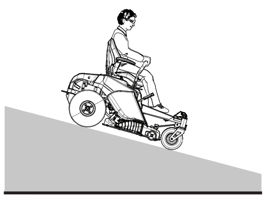
SLOPE OPERATION
Travel in the manufacturer recommended direction on slopes. Use caution while operating near drop-offs.
Do not operate machine under any condition where traction, steering, or stability is in question. Tires could slide even if the wheels are stopped.
Always keep the machine in gear when going down slopes. Do not coast downhill.
Use extreme caution when operating on slopes.
Do not remove or modify any wheels.
Watch for holes, ruts, bumps, rocks or other hidden objects. Uneven terrain could overturn the machine. Tall grass can hide obstacles.
Remove obstacles such as rocks, tree limbs, garbage etc.
Keep all movement on slopes slow and gradual. Do not make sudden changes in speed or direction.
Avoid starting and stopping on a slope. If tires lose traction, disengage the blades and proceed slowly straight down the slope.
Mow a safe distance (minimum of 10 feet, or 3 meters) away from drop-offs, retaining walls, drainage ditches, embankments, water, and other types of hazards to avoid a wheel dropping over the edge or the ground breaking away. This will reduce the risk of the machine suddenly rolling over, which could cause either serious injury or death.
Use a walk-behind, push mower or hand-held trimmer on slopes and near drop-offs, retaining walls, drainage ditches, embankments and water.
Do not mow on wet grass. Reduced traction could cause sliding and loss of steering control.
Do not tow on slopes. The weight of the towed equipment may cause loss of traction and control.
If the mower’s tires lose traction when operating on slopes, disengage the deck drive, place the steering control levers in the park brake position, press the push button switch, remove the magnetic bar and get help.
Never make sudden starts, stops, turns, or reverse direction, especially when maneuvering on slopes. The steering is designed for sensitive response. Rapid movement of the steering control levers in either direction could result in a reaction of the machine that can cause serious injury.
Never stop suddenly while backing down slopes. This action may result in a reaction of the machine that can cause serious physical injury.
The Greenworks mower is capable of operating horizontally (traverse) on moderate slopes. When operating on slopes up to 15 degrees, take care of any conditions that may cause the mower drive tires to lose traction, resulting in a possible loss of control of the machine. An operator should not operate on a slope until he is thoroughly familiar with the equipment.
Do not operate on slopes greater than 15 degrees.
Refer to Slope Guide, when determining the degree of slope to be mowed. It is strongly recommended that the operator drive the machine off of the slope, using extreme caution, if any sign of loss of traction is detected. Wait until the condition that caused the problem is resolved before attempting to operate on the slope again. Terrain conditions can affect traction, resulting in possible loss of control of the machine. Some of the conditions to be aware of are:
Wet terrain
Depressions in the ground (e.g., holes, ruts, washouts)
Mounds of dirt
Certain types of soil (e.g., sand, loose dirt, gravel, clay)
Grass type, density, and height
Extremely dry conditions
Tire pressure
The attachments mounted to the mower will also affect the way it handles on a slope. Be aware that each attachment’s characteristics vary.
These are just a few examples of situations where caution must be used when operating on a slope. There are many other possibilities too numerous to mention. Remember to always exercise extreme caution while operating on any slope.
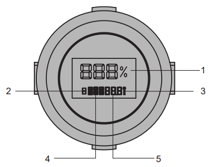
DIGITAL DISPLAY
The function of the digital display, located on the control panel, is to provide electrical system information to the operator. It gives detailed information in the form of pattern, codes and number.
DIGITAL DISPLAY
#
Name
Meaning
1
Battery remaining capacity
2
Hourglass
3
Controller fault/ battery fault/ motor fault/ Vehicle fault
4
Fault position
5
Fault code/ total working hours
FAULTS
The Canbus system will take action to protect the user and machine when it detects an issue. When it acts to turn off the machine or a component, it will indicate that a fault has occurred, and that fault will be shown on the digital display. All electrical faults have a letter code followed by a number. The first letter describes the system that caused the fault according to this chart:
FOR RZ SERIES
TR
Right Driver Controller and motor
TL
Left Driver Controller and motor
PMU
Power management unit (in the battery cabin)
MR
Right Blade Controller and motor
ML
Left Blade Controller and motor
FAULT CODE
Display
Description
Fault code on LCD
Cause
Solution
The left steering control lever fails.
The potentiometer on the left steering control lever fails.
V17
The potentiometer fails.
Contact a specified service center.
The potentiometer connector on the left steering control lever is loose.
The connector is loose.
The right steering control lever fails.
The potentiometer on the right steering control lever fails.
V18
The potentiometer fails.
Contact a specified service center.
The potentiometer connector on the right steering control lever is loose.
The connector is loose.
The machine does not work when the machine is powered on.
Before the machine is powered on, the PTO switch is ON.
V15
Before the machine is powered on, the PTO switch, left steering control lever, and right steering control lever are not in the initial position.
Turn off the PTO switch.
Before the machine is powered on, the left steering control lever is
ON.
Turn off the left steer control lever.
Before the machine is powered on, the right steering control lever is
ON.
Turn off the right steer control lever.
After the whole machine is powered on, the output signal of the left or right accelerator is abnormal.
Contact a specified service center.
The PTO switch is on when the machine is powered on, but the operator is not in the seat.
V16
The operation is not correct.
Push down the PTO switch.
The left steering control lever is not in the Neutral postion when the machine is powered on, but the operator is not in the seat.
Make sure the left steering control lever is in the N position.
The right steering control lever is not in the Neutral postion when the machine is powered on, but the operator is not in the seat.
Make sure the right steering control lever is in the N position.
The operator leaves the seat during operation.
Do not leave the seat. (except emergent conditions.)
The operator is in the seat, and the machine is powered on, one steering control lever is in the Neutral position but the other is not.
Return the steering control levers to the N position when the operator leaves the seat.
The left or right drive motor does not work.
The 9pin connector between the vehicle wire harness and the left drive controller is loose.
V11
The connector is loose.
Contact a specified service center.
The 9pin connector between the vehicle wiring harness and the right drive controller is loose.
V14
The connector is loose.
Contact a specified service center.
The 10pin connector between the vehicle wire harness and the battery compartment is loose.
V21
The connector is loose.
Contact a specified service center.
The 4pin connector between the vehicle wiring harness and the seat switch is loose.
V27
The connector is loose.
Contact a specified service center.
Poor contact of seat switch connector.
Seat switch fails.
The PCBA that controls the left and right drive motors fails.
The 16pin connector between the vehicle wire harness and the left controller is loose , Or the 16pin connector between the vehicle wire harness and the right controller is loose.
V31, TR23
The connector is loose.
Contact a specified service center.
A high-voltage battery pack is inserted in the of the battery compartment.
TR11, TL11
Wrong battery pack applied.
Check the battery pack.
A low-voltage battery pack is inserted in the of the battery compartment.
TR12, TL12
Wrong battery pack applied.
Check the battery pack.
The power of the battery pack in the of the battery compartment is too low.
The battery capacity is not high enough.
The left or right drive motor does not work.
The right gearbox is stuck.
TR14
The right gearbox fails.
Contact a specified service center.
The left gearbox is stuck.
TL14
The left gearbox fails.
Contact a specified service center.
The 6pin connector between the right drive controller and the right drive motor is loose.
TR15
The connector is loose.
Contact a specified service center.
The right drive motor fails.
The motor fails.
The 6-pin connector between the left drive controller and the right drive motor is loose.
TL15
The connector is loose.
Contact a specified service center.
The left drive motor fails.
The motor fails.
The connector between the right solenoid valve and the right drive controller is loose.
TR16
The connector is loose.
Contact a specified service center.
The right solenoid valve fails.
The solenoid valve fails.
The connector between the left solenoid valve and the right drive controller is loose.
TL16
The connector is loose.
Contact a specified service center.
The left or right drive motor does not work.
The left solenoid valve fails.
The solenoid valve fails.
The right drive controller temperature is too high.
TR17
The controoler temperature is too high.
Power off the machine, and power on again after the controller cools down for a while.
The left drive controller temperature is too high.
TL17
The right drive motor temperature is too high.
TR18
The motor temperature is too high.
Power off the machine, and power on again after the controller cools down for a while.
The left drive motor temperature is too high.
TL18
The right drive motor fails.
TR21
The motor fails.
Contact a specified service center.
The 6pin connector between the right drive motor and the right drive controller is loose.
The connector is loose.
The left drive motor fails.
TL21
The motor fails.
Contact a specified service center.
The 6pin connector between the left drive motor and the left drive controller is loose.
The connector is loose.
The left or right blade does not work.
The communication module of the left blade controller is damaged.
V 12
The left blade controller fails.
Contact a specified service center
The 30pin connector between the vehicle wirie harness and the left blade controller is loose.
The connector is loose.
.
The communication module of the right blade controller is damaged
V 13
The right blade controller fails.
Contact a specified service center
The 30pin connector between the vehicle harness and the right blade controller is loose.
The connector is loose.
The 10pin connector between the vehicle wiring harness and the battery compartment is loose.
V21
The connector is loose.
Contact a specified service center.
The 4pin connector between the vehicle wiring harness and the seat switch is loose.
V27
The connector is loose.
Contact a specified service center.
Poor contact of seat switch contactor.
Seat switch fails.
A high-voltage battery pack is inserted in the of the battery compartment.
ML11
Wrong battery pack applied.
Check the battery pack.
A high-voltage battery pack is inserted in the of the battery compartment.
MR11
Wrong battery pack applied.
Check the battery pack.
The left blade motor fails.
ML13
The motor fails.
Contact a specified service center.
The right blade motor fails.
MR13
The motor fails.
Contact a specified service center.
The left mowing motor is overloaded.
ML14
The motor shut down for protection.
Raise the deck height and reduce drive speed.
The machine is blocked with grass and debris.
Clean the deck.
The blade hit a hard object.
Restart the machine.
The left mowing motor is overloaded.
MR14
The motor shut down for protection.
Raise the deck height and reduce drive speed.
The machine is blocked with grass and debris.
Clean the deck.
The blade hit a hard object.
Restart the machine.
The left or right blade does not work.
The 6 pin connector between the left blade motor and the vehicle wire harness is loose.
ML15
The connector is loose.
Contact a specified service center.
The left blade motor fails.
The motor fails.
The 6 pin connector between the right blade motor and the vehicle wire harness is loose.
MR15
The connector is loose.
Contact a specified service center.
The right blade motor fails.
The motor fails.
The PCBA that controls the left blade motor fails.
ML16, ML18
The PCBA fails.
Contact a specified service center.
The PCBA that controls the right blade motor fails.
MR16, MR18
The PCBA fails.
Contact a specified service center.
The phase wire connector between the left blade motor and the left blade controller is loose.
ML17
The connector is loose.
Contact a specified service center.
The phase wire connector between the right blade motor and the right blade controller is loose.
MR17
The connector is loose.
Contact a specified service center.
The left blade controller temperature is too high.
ML21
The controller temperature is too high.
Power off the machine, and power on again after the controller cools down for a while.
The right blade controller temperature is too high.
MR21
The left or right blade does not work.
The left blade motor fails.
ML22
The motor fails.
Contact a specified service center.
The 6pin connector between the left blade motor and the left blade controller is loose.
The connector is loose.
The right blade motor fails.
MR22
The motor fails.
Contact a specified service center.
The 6pin connector between the right blade motor and the left blade controller is loose.
The connector is loose.
The left blade motor temperature is too high.
ML23
The motor temperature is too high.
Power off the machine, and power on again after the controller cools down for a while.
The right blade motor temperature is too high.
MR23
The 30pin connector between the vehicle wire harness and the right blade controller is loose.
ML25
The connector is loose.
Contact a specified service center.
The 30pin connector between the vehicle wire harness and the right blade controller is loose.
MR25
The connector is loose.
Contact a specified service center.
The battery
compartment
alarms.
PMU is slightly overcurrent or PMU is slightly overtemperature.
PMU11
PMU is slightly overcurrent or PMU is slightly over temperature.
Do not use the machine too much to avoid machine shut down.
The PMU shutdown protection is triggered.
PMU12
The working environment is bad, PMU protection triggered.
Restart the machine.
The power of the machine is too low.
Check the battery capacity.
The battery compartment fails.
Contact a specified service center.
The battery inserted does not work (not specified battery).
PMU13
Battery pack is not applicable.
Only use specified battery pack.
Defective battery pack inserted.
Defective battery pack applied.
Make sure the battery pack is OK.
MAINTENANCE
Regular maintenance is the best prevention for costly downtime or expensive, premature repair. The following pages contain suggested maintenance information and schedules which the operator should follow on a routine basis. For more detailed information, refer to the website for your unit. Remain alert for unusual noises, as they could be signaling a problem. Visually inspect the machine for any abnormal wear or damage.
MOWER BLADE MAINTENANCE
Check the mower blades daily. They are the key to power efficiency and well-groomed turf. Keep them sharp -- a dull blade will tear rather than cut the grass, leaving a brown ragged top on the grass within a few hours. A dull blade also requires more power. Replace any blade that is bent, cracked or broken.
WARNING: Never attempt to straighten a bent blade by heating, or weld a cracked or broken blade as the blade may break and cause serious injury. Replace worn or damaged blades.
WARNING: Never work with blades while key is in the ignition switch. Turn key to “OFF” position, remove the battery packs from the machine. Block up mower when you must work under it. Wear gloves when handling blades. Always check for blade damage if mower strikes a rock, branch or other foreign objects!
DANGER: Touch-up sharpening can be done with a file. Check the blades for balance following grinding. A commercial balancing tool is available through most hardware supply stores, or balancing can be done by placing the blade on an inverted line punch or 1/2" bolt. Blade should not lean or tilt. While spinning the blade slowly, it should not wobble. If blade is out of balance, true it up before reinstalling. Lay the blade on a flat surface and check for distortion. Replace any distorted blade.
WARNING:
• The blade sail (curved part) must be pointing upward toward the inside of the deck to ensure proper cutting.
• When mounting blades, rotate them after installation to ensure blade tips do not touch each other or sides of the mower.
• Failure to correctly torque the bolt may result in the loss of the blade, which can cause serious injury.
• Mower blades are sharp and can cut. Wear gloves and use extra caution when servicing them.
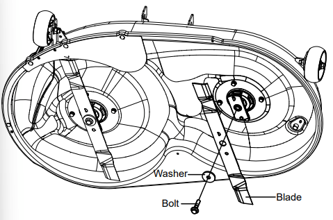
REPLACE THE BLADE
1. Stop the motor, remove the start key, and set the parking brake.
2. Raise the height of the cutting deck to its highest position to allow access to blades.
NOTE: If necessary, raise the mower by placing on a lift or using a jack and jack stands, or remove the cutting deck as described in the previous section to gain access to the blades.
WARNING:
If raising the mower to access the blades, make sure the mower is properly secured and the parking brake is set before proceeding. Failure to properly secure the mower could cause it to fall, resulting in death or possible serious personal injury.
3. Wedge a block of wood between the blade and mower deck to prevent the blade from turning.
4. Loosen the blade nut by turning it counterclockwise (as viewed from bottom of mower) using a 16 mm wrench or socket (not provided).
5. Remove the blade nut, spacer, blade insulator, and blade.
6. Thread the blade nut on the shaft and finger tighten.
7. Torque the blade nut down clockwise using a torque wrench (not provided) to ensure the bolt is properly tightened. The recommended torque for the blade nut is 796~885 in. lbs.
WARNING: Ensure blade is properly seated and the blade nut is tightened to the torque specifications above. Failure to properly attach the blade could cause it to come loose and result in possible serious personal injury.
8. Repeat with the second blade, if needed.
NOTE: Make certain all parts are replaced in the exact order in which they were removed.
TIRES
It is important for level mowing that all tires have the correct amount of air pressure. The recommended pressure are:
NOTE: Tire pressure should only be measured or adjusted when tires are cold.
Front caster wheels
37 psi
Drive wheels
8 psi
NOTE: Inspect the tires daily. Replace immediately if damaged.
WARNING: Check the tire pressure carefully while inflating. Too much air in the tire could cause the tire to burst, causing serious personal injury.
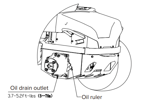
LUBRICATION
Please add oil before operation.
Oil type
SAE85W-140
Oil capacity
180 ml
Contact your Greenworks dealer to replace the lubrication.
NOTE: Replace the gearbox oil after you operate the machine for 50 hours for the first time, then replace the oil every 200 hours.
TORQUE VALUES
WARNING: Particular attention must be given to tightening the drive wheel lug nuts and blade spindle bolts. Failure to correctly torque these items may result in the loss of a wheel or blade, which can cause serious damage or personal injury.
Torque values are given below:
Part
Ft-lbs.
Nm
Wheel (lug) nuts
89
120
Blade spindle bolt
66
90
Lug nuts only -It is recommended that these be checked after the first 2 hours of operation, initially, every 100 hours and following removal for repair or replacement.
For all other torques refer to the various mower parts manuals for standard torque chart.
BATTERY PACK MAINTENANCE
Your Greenworks mower is powered by a battery pack which, when maintained properly, will provide years of useful life. For proper care, adhere to the following instructions:
Always charge batteries after each use.
Whenever a battery pack is fully discharged and turned off, it is best to recharge the battery as soon as possible. Over-discharge of the battery pack means the battery life will be shortened and the battery may become permanently damaged. There is no need to fully charge; it will be beneficial even if you only charge the battery pack for 5-10 minutes. It is best to recharge it within 24 hours.
Check that battery cables are securely tightened to batteries each time you service the battery.
Keep grass, dirt and debris from collecting near battery terminals and in battery area.
Charge batteries indoors in a well-ventilated and dry location away from sparks or flames. Never expose charger to rain, vapor or liquid.
Charge only lithium batteries provided by Greenworks.
Do not touch uninsulated portion of charger (terminal pins) or of output connector.
Do not use with defective cords and wires. Replace defective cords and wires immediately.
For long-term storage, please make sure the storage temperature is -4°F - 113°F within one month, and 32°F -95°F between two and 12 months.
The working environment of the battery pack is 14°F -113°F. Battery pack can be used a -5°F - 131°F for discharge, and 32°F - 107°F for charge.
BATTERY COMPARTMENT FILTER MAINTENANCE
Replace the battery compartment filter every 200 hours.
SERVICE
IMPORTANT:
Wait for all movement to stop before adjusting, cleaning or repairing. Repairs or maintenance requiring power should be performed by trained maintenance personnel only. Read and observe safety warnings in front of manual.
Repairs or maintenance requiring power should be performed by trained maintenance personnel only.
Park the mower on level ground. Make sure that steering control levers are in the neutral position, and that the PTO switch is in “OFF” position. Raise deck, rotate key to “OFF” position, remove key from switch and remove the battery packs from the battery compartment under the seat.
Any maintenance operation that requires the removal of safety covers must be performed by a trained service technician.
Use a stick or similar instrument to clean under the mower, making sure that no part of the body -- especially arms and hands -- is under mower.
Keep your machine clean and remove any deposits of trash and clippings.
Keep battery compartment, deck and operator’s station clean of accumulated trash, grass clippings, and other debris.
Clean battery compartment, drive motor compartment, mower deck, seat, etc., of all dirt and debris. To clean, use only compressed air. DO NOT use water, solvents, hard cleaners or abrasives.
Always wear adequate eye protection when servicing the batteries or when grinding mower blades and removing accumulated debris. Never attempt to make any adjustments or repairs to the mower’s drive system, mower deck or any attachment while the traction drive system is running. Repairs or maintenance requiring power should be performed by trained maintenance personnel only.
Never work under the machine or attachment unless it is safely supported with jack stands. Make certain machine is secure when it is raised and placed on the jack stands.
The jack stands should not allow the machine to move when the traction drive system is running and the drive wheels are rotating. Use only certified jack stands. Use only appropriate jack stands, with a minimum weight rating of 2000 pounds (907.2 kg) to block the unit up.
Use in pairs only. Follow the instructions supplied with the vehicle stands.
Do not touch hot parts of machine.
Keep nuts and bolts tight, especially the blade attachment bolts. Keep equipment in good working condition.
Never tamper with safety devices. Check their proper operation regularly.
Turn the key to the “OFF” position before unclogging the discharge chute.
Never clear the discharge chute with the machine running. Turn the key to the “OFF” position and be sure the blades have stopped before cleaning. Use a stick to clear a plugged discharge area. Never use your hand!
Stop unit and allow blades to stop before unclogging chute. Grass collection system components are subject to wear, damage and deterioration, which could expose moving parts or allow objects to be thrown. Frequently check components and replace with manufacturer’s recommended parts, when necessary.
Exercise caution when working under the deck as the mower blades are extremely sharp. Wear gloves and use extra caution when servicing them.
Use only genuine Greenworks Mower parts to ensure that original standards are maintained.
Always remove batteries when transporting unit. Keep unit free of grass clippings, leaves and other debris.
Check brake operation frequently. Adjust and service as required.
Maintain or replace safety and instruction labels, as necessary.
Have your ride-on lawn mower serviced by a qualified repair person using only identical replacement parts. This will ensure that the safety of the ride-on lawn mower is maintained.
Recharge only with the charger specified by the manufacturer. A charger that is suitable for one type of battery pack may create a risk of fire when used with another battery pack.
CLEANING AND STORAGE
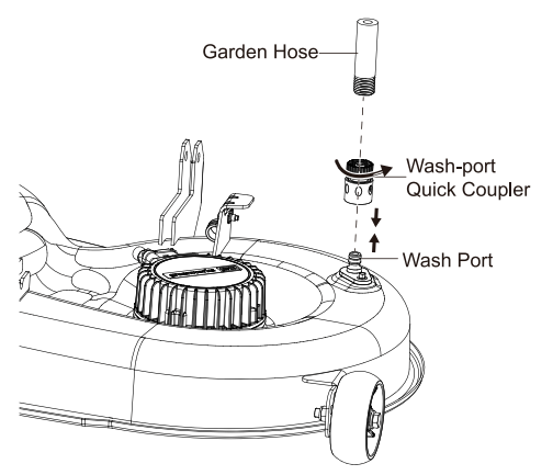
CLEAN THE MOWER DECK
Set the parking brake into the parking slots. Refer to section PARKING BRAKE SETTING in this manual.
Adjust the mower deck height to the lowest. Refer to section "CUTTING-DECK HEIGHT ADJUSTMENT" in this manual.
Attach the supplied wash-port quick-coupler to garden hose.
Attach garden hose with quick-coupler to wash port on the mower deck. The wash port is on the left side of the mower deck.
Turn on the water.
Pull the PTO switch to start the mower cutting blades and adjust the blade speed to the highest. Refer to section "Blade-Speed Adjustment Button" in this manual.
Flush water under the deck for approximately one minute.
Disengage the mower blades by pushing the PTO switch downward.
Turn off the water and remove garden hose and quick-coupler from wash port.
Remove quick-coupler from garden hose and store for future use.
Turn off the mower completely. See section "STOPPING THE ELECTRIC ZERO TURN MOWER".
STORE THE MACHINE
The following steps should be taken in order to prepare the machine for storage.
Clean the machine as described in the previous section.
Inspect the blade and replace it or sharpen it, if required (refer to the Maintenance section).
Do not store the machine next to corrosive materials, such as fertilizer or rock salt.
Keep the machine out of the reach of children.
Do not cover the machine with a solid plastic sheet.
Plastic coverings trap moisture around the machine, which causes rust and corrosion.
Check thoroughly for any worn or damaged parts that need replacing and order them from your dealer.
Thoroughly lubricate machine, according to lubrication instructions.
Fully charge and service the batteries.
Do not deflate tires.
The machine should be stored in a well-ventilated, clean and dry place.
PREPARE FOR USE AFTER STOAGE
The following steps should be taken before using the mower after it has been stored:
Fully charge the batteries.
Check tire pressure and inflate as needed.
Briefly drive the mower and check all systems and components to ensure they are functioning correctly.
TROUBLESHOOTING
Problem
Cause
Solution
The machine does not move.
1. There is no battery pack in the battery compartment, or the battery inserted is not Greenworks designed.
2. The battery pack is out of power.
3. The steer control lever is in the NUETRAL position.
4. There is no person sitting on the seat or the seat switch is not connected.
5. The PTO switch, or the the left and right steer control levers are not in the original position when the machine power is on.
6. The battery pack that controls the drive function is in sleep state.
1. Make sure at least one Greenwoks designed battery pack is inserted in the battery compartment.
2. Check the battery capacity.
3. Make sure the steer control levers are not in the parking slots.
4. Make sure the operator is sitting on the seat.
5. Return the steer control lever and PTO switch to the original position, restart the machine. If the machine still fails to work, contact the service center for help.
6. Turn the key to the OFF position, and restart the machine 5 seconds later.
Sudden breakdown during driving.
1. The battery is out of power.
2. The seat switch is disconnected on rugged or bumpy roads.
3. The accelerator fails.
4. The vehicle controller fails.
1. Make sure at least one Greenwoks designed battery pack is inserted in the battery compartment. Make sure the battery pack has power.
2. Return the steer control lever to original position, restart the machine, operate the steer control lever to check if the machine works normally.
3. Contact a technical people for help.
The blade fails to run when you pull up the PTO switch.
1. There is no Greenwoks designed battery pack in the battery compartment.
2. The battery pack is out of power.
3. The seat switch is not connected.
4. The PTO switch is not pushed when the machine is powered on.
5. The blade motor is blocked or other functional protection.
1. Make sure at least one Greenwoks designed battery pack is inserted in the battery compartment. Make sure the battery pack has power.
2. Check the battery capacity.
3. Make sure the operator is sitting on the seat.
4. Push down on the PTO switch, restart the machine.
5. Cut the grass in low blade speed when you power on the machine, set the blade speed to high position once the machine cuts normally. Check if the connection between the blade and motor is without grass or foreign objects to ensure the blade rotates smoothly.
6. Turn the key to the OFF position, and restart the machine 5 seconds later.
The blade stops running during the mowing process.
1. The blade motor is overheated.
2. The deck is full of grass and garbage.
3. The blade motor is overloaded.
4. The battery pack termperature is too high.
5. The battery is undervoltage.
6. The blade is hit by a foreign object, causing the blade to stop suddenly for protection.
1. Do not use the machine too much, power off the machine for 5min. Raise the deck height or reduce the driving speed to protect the blade.
2. Clean the deck to ensure that the blade rotation is normal.
3. Push down on the PTO switch; restart the machine. Raise the deck height or reduce the drive speed to protect the blade.
4. The battery pack that controls the blade system enters under-voltage protection state, and the battery should be charged immediately
5. Turn the key to the OFF position, and restart the machine 5 seconds later.
The machine cuts the grass unevenly.
1. The blade is dull.
2. The blade is bent.
3. The deck is uneven.
1. Grind the blade according to the manual.
2. Replace the bent blade, replace the blade according to the instructions in the manual, and wear protective equipment.
3. Adjust the cutting deck according to the instructions in the manual to ensure the left and right deck height are even.
The actual cut height does not match the cut height you set.
1. The bolt of the deck is loose.
2. The deck is severely worn or damaged.
1. Adjust the cutting deck bolt, make sure the deck is not loose. Please balance the deck level after each adjustment.
2. Replace with a new cutting deck.
The machine cuts the grass abnormally.
1. The grass is too wet.
2. The grass amount you set is too much.
1. Please check the grass before working. If the grass is too wet, please wait until the grass gets drier.
2. If the grass is too intensive and high, raise the deck height, and avoid cutting intensive grass.
The machine vibrates too much.
1. The blade is loose.
2. The blade is bent.
3. The deck is uneven.
4. The deck is loose.
5. The blade cuts too much grass more than the amount you set.
1. Grind the blade according to the manual.
2. Replace the bent blade, replace the blade according to the instructions in the manual, and wear protective equipment.
3. Adjust the cutting deck according to the instructions in the manual to ensure the left and right deck height are even.
4. Tighten the fixing bolts of the deck.
5. If the grass is too intensive and high, please raise the cutting deck and try to avoid cutting intensive grass.
There is grass or debris on the ground after mowing.
1. The blade cuts too much grass more than the amount you set.
2. The grass is too wet.
3. You drive too fast.
4. The blade speed is too low.
1. If the grass is too dense and high, please raise the cutting deck. If the grass height exceeds 6 inch, please cut the area repeatedly. Try to avoid cutting intensive grass.
2. Please check the grass before working. If the grass is too wet, please wait until the grass gets drier.
3. Reduce the drive speed.
4. Turn the blade speed to high position.
The cutting endurance time is short.
Heavy grass can short the running time of the lawn mower.
Raise the cutting deck and reduce the blade speed to extend the running time.
The machine is off the track.
The tire pressure of the left and right rear wheel is different.
Check the tire pressure of the machine regularly according to the instructions.
The machine fails to start after cleaning.
Improper cleaning, water enters electronic components such as LCD or battery compartment.
1. When cleaning the machine, please clean it according to the instructions.
2. If the vehicle is accidentally exposed to rain, please put the vehicle in a dry place for 12 hours or dry it before use.
3. Contact a service center for help.
The mower is blocked.
The deck is full of weeds and garbage.
Please clean the machine correctly according to the instructions after each use.
The machine quickly moves down the slope even if you engage the neutral bypass knob.
1. Tire wear is too serious.
2. The neutral bypass knob is damaged or severely worn out.
3. Check if the neutral bypass knob is disengaged by someone.
1. Contact a service center to replace the tire or neutral bypass knob.
2. Check if the neutral bypass knob is disengaged by someone.