Loading ...
Loading ...
Loading ...
24
W415-1401 / C / 03.18.15
EN
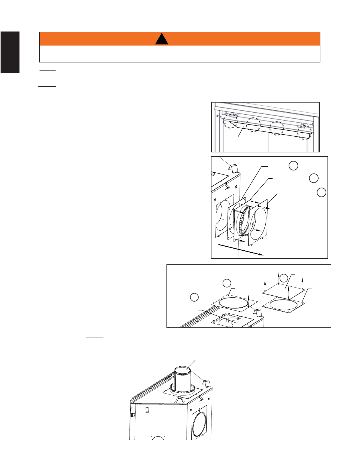
3.12 TOP EXIT
A. Remove the safety screen and glass front, refer to " SAFETY SCREEN & DOOR REMOVAL /
INSTALLATION" section.
B. Remove the contents from the fi rebox and set aside, you
will need the fl ue collar from the top of the log carton.
C. To ease assembly, remove the four hex head screws
securing the defl ector from inside the top front of the
fi rebox.
D. Remove the single screw from the outer cover on the
back of the appliance.
E. Remove the four screws on the 7" (178mm) intake collar
assembly; set the intakecollar and gasket aside. Careful
not to damage gasket.
F. Remove the single screw from the outer cover with
knockout intact, on the top of the appliance and set
aside.
G. Remove the inner cover plate and gasket by removing
the four screws. Reinstall the inner cover plate and
gasket onto the back of the appliance.
H. Take the outer cover (with knockout intact) and secure
onto the back of the appliance.
I. Remove and discard the 1 1/2" thick batt of insulation.
J. Place the 7" (178mm) intake collar and gasket into the
top of the appliance and secure with
the four screws.
K. Re-install the outer cover (without
knock out) over the 7" (178mm)
exhaust collar assembly and secure.
L. From inside the fi rebox, install the 4"
(102mm) exhaust collar up through the
top of the fi rebox and secure with the
the four hex head 3/8" thread cutting
screws. NOTE: Do not overtighten.
The gasket needs only to be snug against the fi rebox.
M. Re-attach the top defl ector, log set, glass door and safety screen.
NOTE: This appliance has been factory shipped as a rear vent.
EXHAUST FLUE COLLAR
INTAKE COLLAR
ASSEMBLY
GASKET
OUTER COVER
D
E
E
INNER
COVERPLATE
OUTER SHELL
KNOCKOUT
GASKET
F
F
G
OUTER
COVER
(with knockout)
!
WARNING
FAILURE TO INSTALL THE CAP WILL CAUSE THE APPLIANCE TO FUNCTION IMPROPERLY AND
CAN CAUSE INJURY OR PROPERTY DAMAGE.
DEFLECTOR
NOTE: A #42 orifi ce was supplied with your appliance. In installations with a vertical rise greater than
8" (203mm) in the vent confi guration, the #42 orifi ce must be used to increase the fl ame size.
Loading ...
Loading ...
Loading ...