Loading ...
Loading ...
Loading ...
X Lockwasher,1/4 in.ExternalType
(approx.dia.of hole 1/4 in.) ................ 8
X Lockwasher,5/16 in. ExternalType
(approx.dia.ofhole5/16 in.) ............... 4
Z HexHd.Screw,5/16-18 x 1-1/2 in.long ........ 2
Z HexHd.Screw,5/16-18 x 1 in. long ........... 2
BB TrussHeadScrew,1/4-20x 5/8 ............... 4
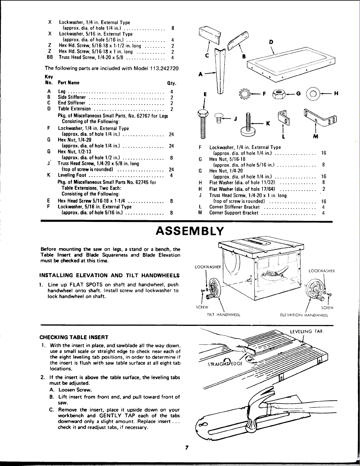
The following parts are included with Model 113.242720
Key
No. Part Name Qty.
A Leg ..................................... 4
B Side Stiffener ............................. 2
C End Stiffener ............................. 2
D Table Extension ........................... 2
Pkg. of MiscellaneousSmall Parts, No. 62767 for Legs
Consistingof the Following:
F Lockwasher, 1/4 in. External Type
(approx. dia. of hole 1/4 in.) ................ 24
G Hex Nut, 1/4-20
(approx. dia. of hole 1/4 in.) ................ 24
G Hex Nut, 1/2-13
(approx. dia. of hole 1/2 in.) ................ 8
J" Truss Head Screw, 1/4-20 x 5/8 in. long
(top of screw isrounded) .................. 24
K Leveling Foot ............................. 4
Pkg. of MiscellaneousSmall Parts No. 62745 for
Table Extensions, Two Each:
Consisting of the Following:
E Hex Head Screw 5/16-18 x 1-1/4 .............. 8
F Lockwasher, 5/16 in. External Type
(approx. dia. of hole 5/16 in.) ............... 8
¢
A ......-4
E
l
F
G
G
H
H
J
L
M
D
B
H
L M
Lockwasher,1/4 in. ExternalType
(approx.dia.of hole 1/4 in.) ................ 16
Hex Nut, 5/16-18
(approx.dia.of hole5/16 in.) ............... 8
Hex Nut, 1/4-20
(approx.dia.of hole1/4 in.) ................ 16
Flat Washer(dia.of hole 11/32) .............. 8
Flat Washer(dia.of hole 17/64) .............. 2
TrussHeadScrew,1/4-20 x 1in. long
(top ofscrewisrounded) .................. 16
CornerStiffener Bracket .................... 4
CornerSupport Bracket ..................... 4
ASSEMBLY
Before mounting the saw on legs,a stand or a bench, the
Table Insert and Blade Squareness and Blade Elevation
must bechecked at this time.
INSTALLING ELEVATION AND TILT HANDWHEELS
1. Line up FLAT SPOTS on shaft and handwheel, push
handwheel onto shaft. Install screw and Iockwasher to
lock handwheel on shaft.
LOCKWASHER
LOCKWASHER
SCREW SCREW
TILT HANDWHEEL ELEVATION HANDWHEEL
CHECKING TABLE INSERT
I.
With the insert in place, and sawblade all the way down,
use a small scale or straight edge to check near each of
the eight leveling tab positions, in order to determine if
the insert is flush with saw table surface at all eight tab
locations.
2.
If the insert is above the table surface, the leveling tabs
must be adjusted.
A. Loosen Screw.
B. Lift insert from front end, and pull toward front of
saw.
C. Remove the insert, place it upside down on your
workbench and GENTLY TAP each of the tabs
downward only a slight amount. Replace insert...
check it and readjust tabs, if necessary.
- LEVELING TAB
Loading ...
Loading ...
Loading ...