Loading ...
Loading ...
Loading ...
29
SERVICE AND MAINTENANCE
3. Remove the hex flange nut that secures the blade to the spindle assembly.
See Figure 15.
4. To properly sharpen the cutting blades, remove equal amounts of metal
from both ends of the blades along the cutting edges, parallel to the trailing
edge, at a 25° to 30° angle.
IMPORTANT: If the cutting edge of the blade has already been sharpened to
within 1-⁄” from the edge, or if any metal separation is present, replace the
blades with new ones. See Figure 16.
1-5/8 inch
(min.)
Figure 16
CAUTION
If the cutting edge of the blade has previously been sharpened, or if any
metal separation is present, replace the blades with new ones.
WARNING
A poorly balanced blade will cause excessive vibration, may cause damage
to the tractor and/or result in personal injury.
Test the blade’s balance using a blade balancer. Grind metal from the heavy side
until it balances evenly.
NOTE: When replacing the blade, be sure to install the blade with the side of the
blade marked ‘‘Bottom’’ (or with a part number stamped in it) facing the ground
when the mower is in the operating position.
CAUTION
Use a torque wrench to tighten the blade spindle hex flange nut to
between 70 ft-lbs and 90 ft-lbs.
Changing the Deck Belt
WARNING
Be sure to shut the engine OFF, remove the key, disconnect the spark plug
wire(s) and ground against the engine to prevent unintended starting
before removing the belt.
WARNING
All belts on your lawn tractor are subject to wear and should be replaced if
any signs of wear are present.
IMPORTANT: The V-belt found on your tractor are specially designed to engage
and disengage safely. A substitute (non-OEM) V-belt can be dangerous by not
disengaging completely. For a proper working machine, use factory approved belts.
To change or replace the deck belt on your tractor, proceed as follows:
1. Remove the deck. Refer to Cutting Deck Removal on page 27.
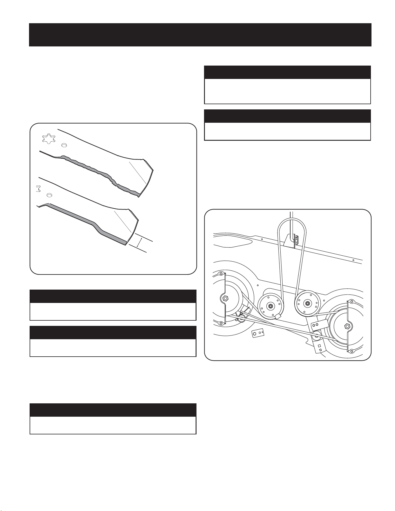
2. Remove the belt covers (a) by removing the hex washer screws (b) that
fasten them to the deck. See Figure 17.
(a)
(a)
(b)
(b)
(b)
(b)
(c)
(d)
(e)
(c)
(f)
(f)
Figure 17
3. It may also be necessary to loosen the hex nut on the left idler pulley (c) to
get the belt off the pulley and around the belt guard (d).
4. Carefully remove the deck belt (e) from around the two spindle pulleys (f)
and the two deck idler pulleys (c). See Figure 17.
5. To place the new belt, begin by routing the belt around the two spindle
pulleys (f). Route the belt around the two deck idler pulleys (c). Retighten
the left idler pulley hex nut loosened in step 3. Remount the belt covers
removed (a) in Step 2. See Figure 17.
6. Re-install the deck, making sure the belt remains routed around the pulleys
as instructed. See Figure 17.
7. Pull the right side of the belt, and place the narrow V side of the belt into the
PTO pulley.
Loading ...
Loading ...
Loading ...