Loading ...
Loading ...
Loading ...
27
SERVICE AND MAINTENANCE
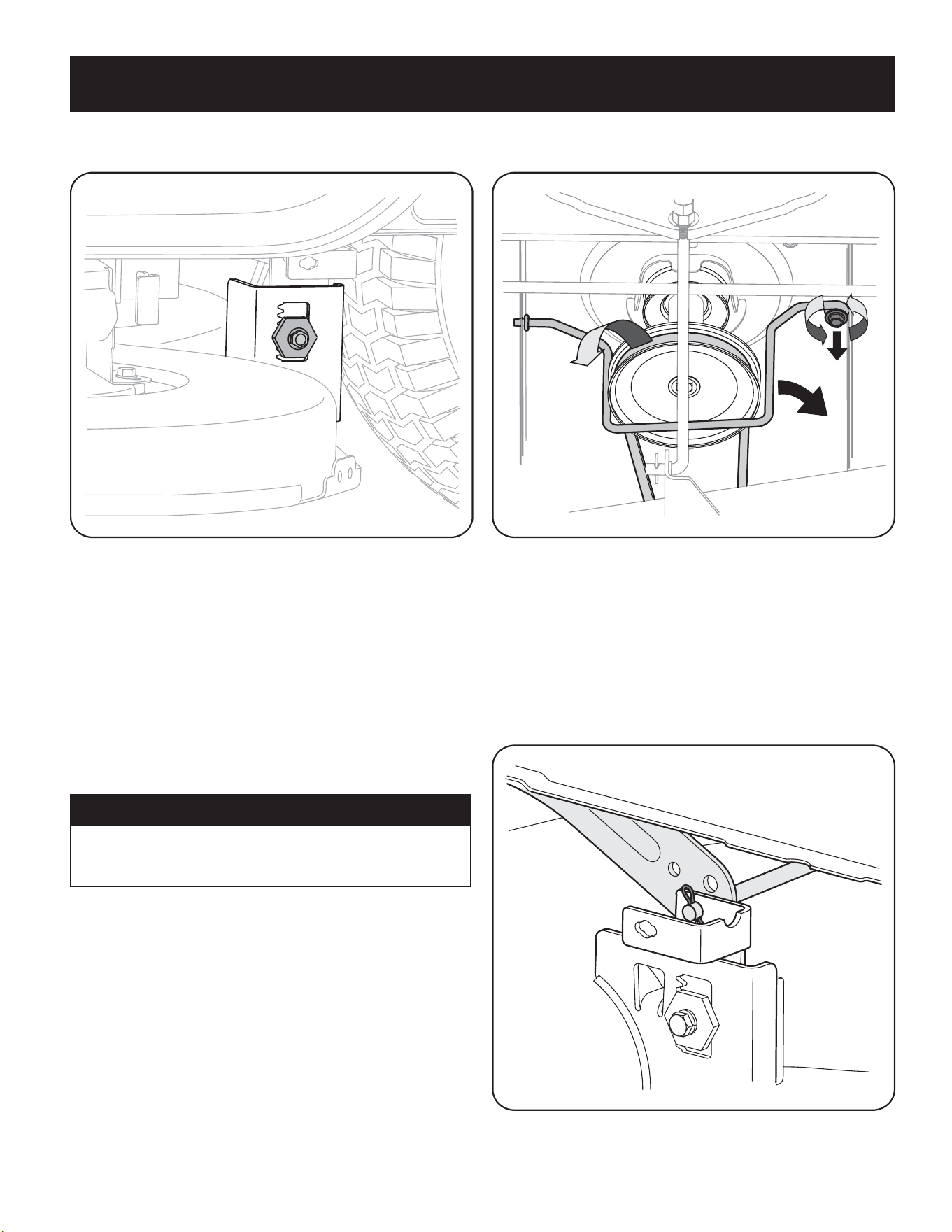
3. Loosen, but do NOT remove, the hex cap screw (a) on the left deck hanger
bracket. See Figure 10.
(a)
Figure 10
4. Balance the deck by using a wrench to turn the adjustment gear (found
immediately behind the hex cap screw just loosened) clockwise/up or
counter-clockwise/down. The deck is properly balanced when both blade tip
measurements taken earlier are equal.
5. Retighten the hex cap screw (a) on the left deck hanger bracket when proper
adjustment is achieved.
Seat Adjustment
Refer to Attaching the Seat in page 10 for seat adjustment instructions.
Parking Brake Adjustment
WARNING
Never attempt to adjust the brakes while the engine is running. Always
disengage PTO, move shift lever into neutral position, stop engine and
remove key to prevent unintended starting.
If the tractor does not come to a complete stop when the brake pedal is completely
depressed, or if the tractor’s rear wheels can roll with the parking brake applied, the
brake is in need of adjustment. See an authorized service dealer to have your brakes
properly adjusted.
Cutting Deck Removal
To remove the cutting deck, proceed as follows:
1. Place the PTO lever in the disengaged (OFF) position and engage the parking
brake.
2. Lower the deck by moving the deck lift lever into the bottom notch on the
right fender.
3. Remove the belt-keeper rod (a), from around the tractor’s engine pulley, by
removing the self-tapping screw (b) that secures it. See Figure 11.
(c)
(b)
(a)
Figure 11
NOTE: Make a note what hole the other end of the belt-keeper rod is inserted
in for reinstallation purposes.
4. Remove the belt (c) from around the tractor’s engine pulley and idler
pulley(s). See Figure 11.
5. Looking at the cutting deck from the left side of the tractor, locate the bow-tie
pin (a) that secures the deck support rod (b) on the rear left side of the deck.
See Figure 12. Remove the bow-tie pin (a) that secures the deck support rod (b),
and carefully remove the deck support from the deck lift arm.
(a)
(b)
Figure 12
6. Repeat step 5 on the tractor’s right side.
Loading ...
Loading ...
Loading ...