Loading ...
Loading ...
Loading ...
STEP4.Loosenorremoveterminal
blockscrews.Connecttheneutralwire.
(whiteorcenter)ofpowersupplycord
underthecenterscrewoftheterminal
block.
STEP5.Connecttheothertwowires
toouterterminalblockscrewsusingthe
samemethod(s)describedinSTEP4.
Tightenallterminalblockscrewsfirmly.
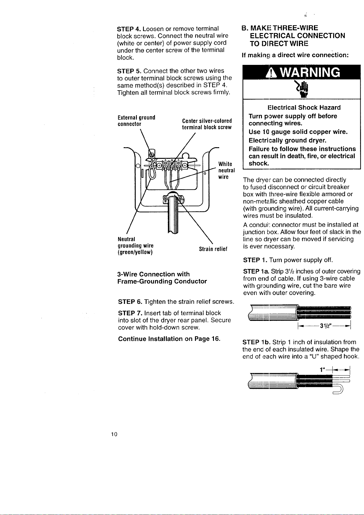
Externalground
connector
Centersilver-c010red
terminalblockscrew
White
neutral
wire
Neutral
groundingwire
(green/yellow)
Strainrelief
3-Wire Connection with
Frame-Grounding Conductor
STEP 6. Tighten the strain relief screws.
STEP 7. Insert tab of terminal block
into slot of the dryer rear panel. Secure
cover with hold-down screw.
Continue Installation on Page 16.
B. MAKE" THREE-WIRE
ELECTRICAL CONNECTION
TO DIRECT WlRI-
If makincl a direct wire connection:
I-lectrical Shock Hazard
Turn power supply off before
connecting wires.
Use 10 gauge solid copper wire.
Electrically ground dryer.
Failure, to follow these instructions
can result in death, fire, or electrical
shock.
The dq/er can be connected directly
to fused disconnect or circuit breaker
box with lhree-wire flexible armored or
non-met_.llic sheathed copper cable
(with grounding wire). All current-carrying
wires must be insulated.
A condui': connector must be installed at
junction box. Allow four feet of slack in the
line so dryer can be moved if servicing
is ever necessary.
STEP 1. Turn power supply off.
STEP la. Strip 31/2inches of outer covering
from end of cable. If using 3-wire cable
with grounding wire, cut the bare wire
even with outer covering.
r='l
t'/
!----
STEP 1b. Strip 1 inch of insulation from
the en_i of each insulated wire. Shape the
end of each wire into a "U" shaped hook.
10
Loading ...
Loading ...
Loading ...