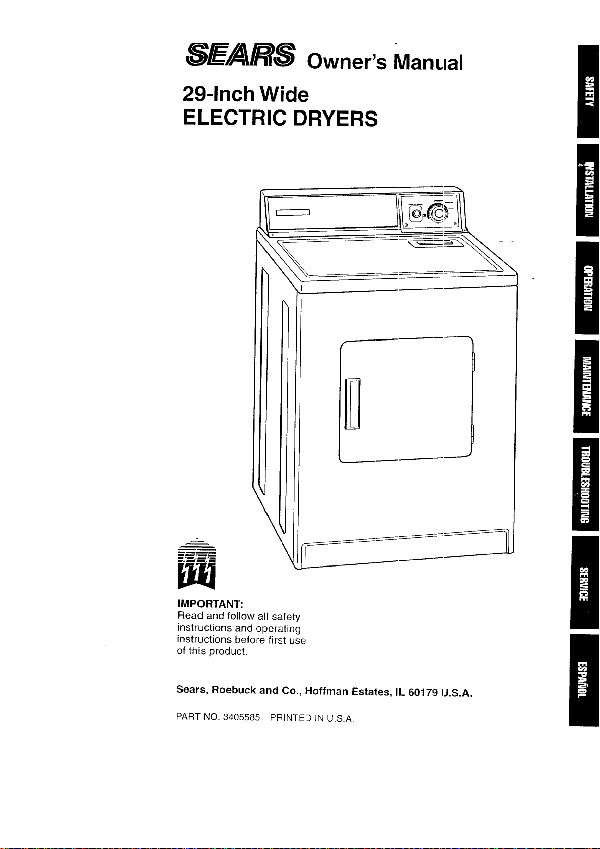
_.__/A/R-_ owner's Manual
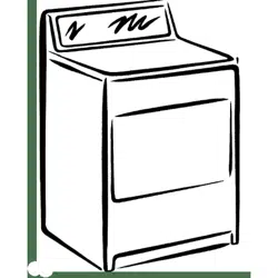
29-Inch Wide
ELECTRIC DRYERS
\l
IMPORTANT:
Read and follow all safety
instructions and operating
instructions before first use
of this product.
Sears, Roebuck and Co., Hoffman Estates, IL 60179 IJ.S.A.
PART NO. 3405585 PRINTED IN U.S.A.

BEFORE USING YOUR NEW DRYER
SEARS ELECTRIC DRYER WARRANTY
IMPORTANT SAFETY INSTRUCTIONS
INSTALLATION INSTRUCTIONS
OPERATING YOUR DRYER
20
CARING FOR YOUR DRYER
22
TROUBLESHOOTING
25
SEARS MAINTENANCE AGREEMENT
27
REQUESTING ASSISTANCE OR SERVICE!
28
2
Please read this manual. It will help you
install and operate your new electric dryer
in the safest and most economical way.
For information about the care and
operation of Sears appliances call your
nearest Sears store. You will need the
complete model and serial numbers
when requesting information. Your dryer's
model and serial numbers are located
on the Model and Serial Number Plate.
Use the ,,;pace below to record the
model number and serial number of
your new electric dryer.
Model No.
Serial Nc.
Date of Purchase
Keep this book and your sales
check (receipt) in a safe place for
future reference.
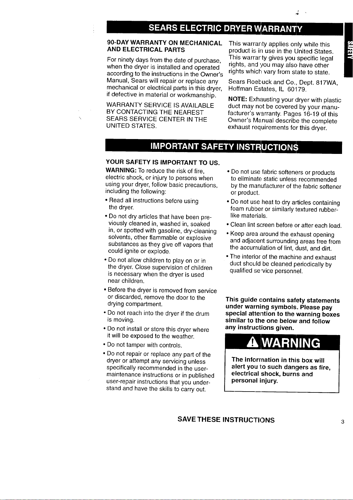
90-DAY WARRANTY ON MECHANICAL.
AND ELECTRICAL PARTS
For ninety days from the date of purchase,
when the dryer is installed and operated
according to the instructions in the Owner's
Manual, Sears will repair or replace any
mechanical or electrical parts in this dryer,
if defective in material or workmanship.
WARRANTY SERVICE IS AVAILABLE
BY CONTACTING THE NEAREST
SEARS SERVICE CENTER IN THE
UNITED STATES.
This warrartty applies only while this
product is in use in the United States.
This warrarty gives you specific legal
rights, and you may also have other
rights which vary from state to state.
Sears Roebuck and Co., Dept. 817WA,
Hoffman I-states, IL 60179.
NOTE: Exhausting your dryer with plastic
duct may not be covered by your manu-
fa(;turer's warranty. Pages 16-19 of this
Owner's Manual describe the complete
exhaust requirements for this dryer.
YOUR SAFETY IS IMPORTANT TO US.
WARNING: To reduce the risk of fire,
electric shock, or injury to persons when
using your dryer, follow basic precautions,
including the following:
• Read all instructions before using
the dryer.
• Do not dry articles that have been pre-
viously cleaned in, washed in, soaked
in, or spotted with gasoline, dry-cleaning
solvents, other flammable or explosive
substances as they give off vapors that
could ignite or explode.
• Do not allow children to play on or in
the dryer. Close supervision of children
is necessary when the dryer is used
near children.
• Before the dryer is removed from service
or discarded, remove the door to the
drying compartment.
• Do not reach into the dryer if the drum
is moving.
• Do not install or store this dryer where
it will be exposed to the weather.
• Do not tamper with controls.
• Do not repair or replace any part of the
dryer or attempt any servicing unless
specifically recommended in the user-
maintenance instructions or in published
user-repair instructions that you under-
stand and have the skills to carry out.
• Do not use fabric softeners or products
to eliminatE, static unless; recommended
by the manufacturer of the fabric softener
or product.
• Do not use heat to dry articles containing
foam rubL_eror similarly textured rubber-
like materials.
• Clean lint screen before or after each load.
• Keep area around the exhaust opening
and adjacent surrounding areas free from
the accumulation of lint, dust, and dirt.
• The interior of the machine and exhaust
duct should be cleaned periodically by
qualified se'vice personnel.
This guide contains safety statements
under warning symbols. Please pay
special attention to the warning boxes
similar to the one below and follow
any instructions given.
The inforrnation in this box will
alert you l:o such dangers as fire,
electrical shock, burns and
personal injury.
SAVE THESE INSTRUCTIONS 3
IMPORTANT:
Observe all governing codes
and ordinances.
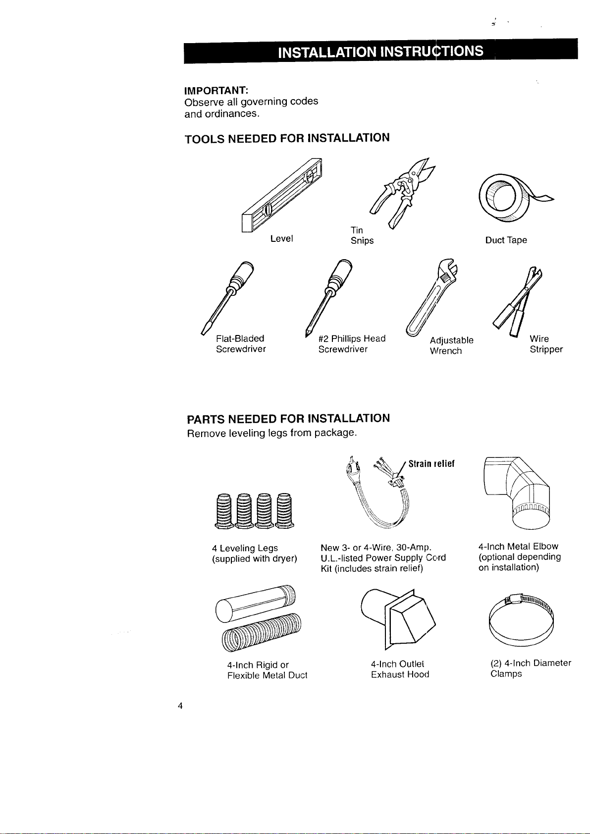
TOOLS NEEDED FOR INSTALLATION
f
Level
Tin
Snips
/'
Flat-Bladed
Screwdriver
_ps Head
Screwdriver
Adjustable
Wrench
Duct rape
Stripper
PARTS NEEDED FOR INSTALLATION
Remove leveling legs from package.
4 Leveling Legs
(supplied with dryer)
_ Strain
New 3- or 4-Wire, 30-Amp.
U.L.-listed Power Supply Cord
Kit (include,'; strain relief)
felief
4-Inch Metal Elbow
(optional depending
on installation)
4-Inch Rigid or
Flexible Metal Duct
4-Inch Outlet
Exhaust Hood
(2) 4-.Inch Diameter
(;lamps

|
LOCATING YOUR DRYER -
STANDARD INSTALLATION
Selecting the proper location for your
dryer makes installation easier and
gives you the best drying performance.
Protect from the weather. Proper
operation of dryer cycles requires
temperatures above 45°F. At lower
temperatures, the dryer may not shut
off at the end of automatic cycles.
Drying times will be extended.
Check code requirements. Some
codes limit or do not permit installation
of clothes dryers in garages, closets,
mobile homes or sleeping quarters.
Contact your local building inspector.
Explosion Hazard
Keep flammable materials and
vapors away from dryer.
Place dryest at least 18 inches above
the floor for a garage installation.
Failure to ¢1oso can result in death,
explosion, fire, or burns.
Check Iocalion where dryer will be installed.
Proper inst;_llation is your responsibility.
Make sure ycu have everything necessary
for correct installation including support,
a level floor and a separate 30-Amp. fuse.
_--_._',. I Separate
___ I 30"A_ilfu_il_ d receptacle:
I' II'l __ =__/ siW_lhionf;; feert,of either
Support: Floormust be sturdy Level floor: 1-inch
enough to support dryer and maximum allowable
load weight of 175 pounds, slope under dryer.
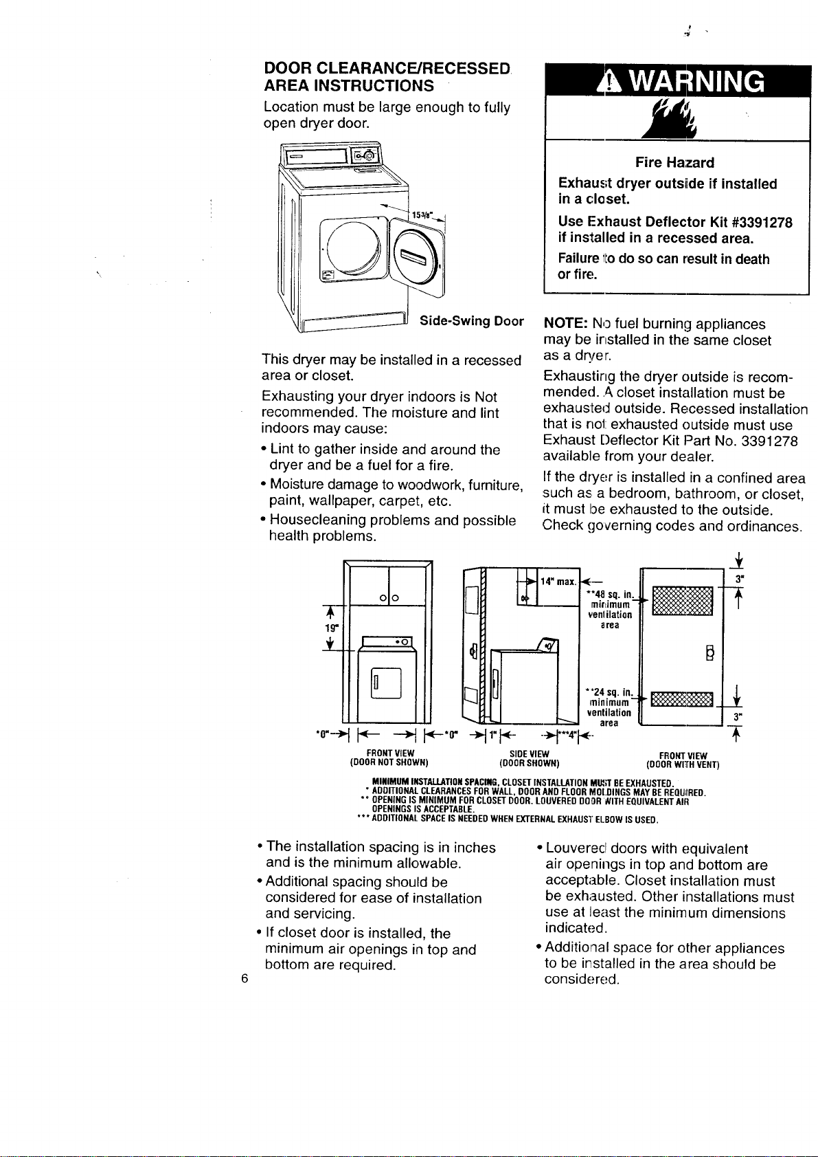
DOOR CLEARANCE/RECESSED
AREA INSTRUCTIONS
Location must be large enough to fully
open dryer door.
Side-Swing Door
This dryer may be installed in a recessed
area or closet.
Exhausting your dryer indoors is Not
recommended. The moisture and lint
indoors may cause:
• Lint to gather inside and around the
dryer and be a fuel for a fire.
• Moisture damage to woodwork, furniture,
paint, wallpaper, carpet, etc.
• Housecleaning problems and possible
health problems.
Fire Hazard
Exhaust dryer outsiide if installed
in a closet.
Use Exhaust Deflector Kit #3391278
if installed in a recessed area.
Failure 1todo so can result in death
or fire,
NOTE: No fuel burning appliances
may be installed in the; same closet
as a dryer.
Exhausting the dryer outside is recom-
mended.._, closet installation must be
exhausted outside. Recessed installation
that is no1:exhausted outside must use
Exhaust Deflector Kit Part No. 3391278
available from your dealer.
If the dryer is installed in a confined area
such as a bedroom, bathroom, or closet,
it must be exhausted to the outside.
Check governing codes and ordinances.
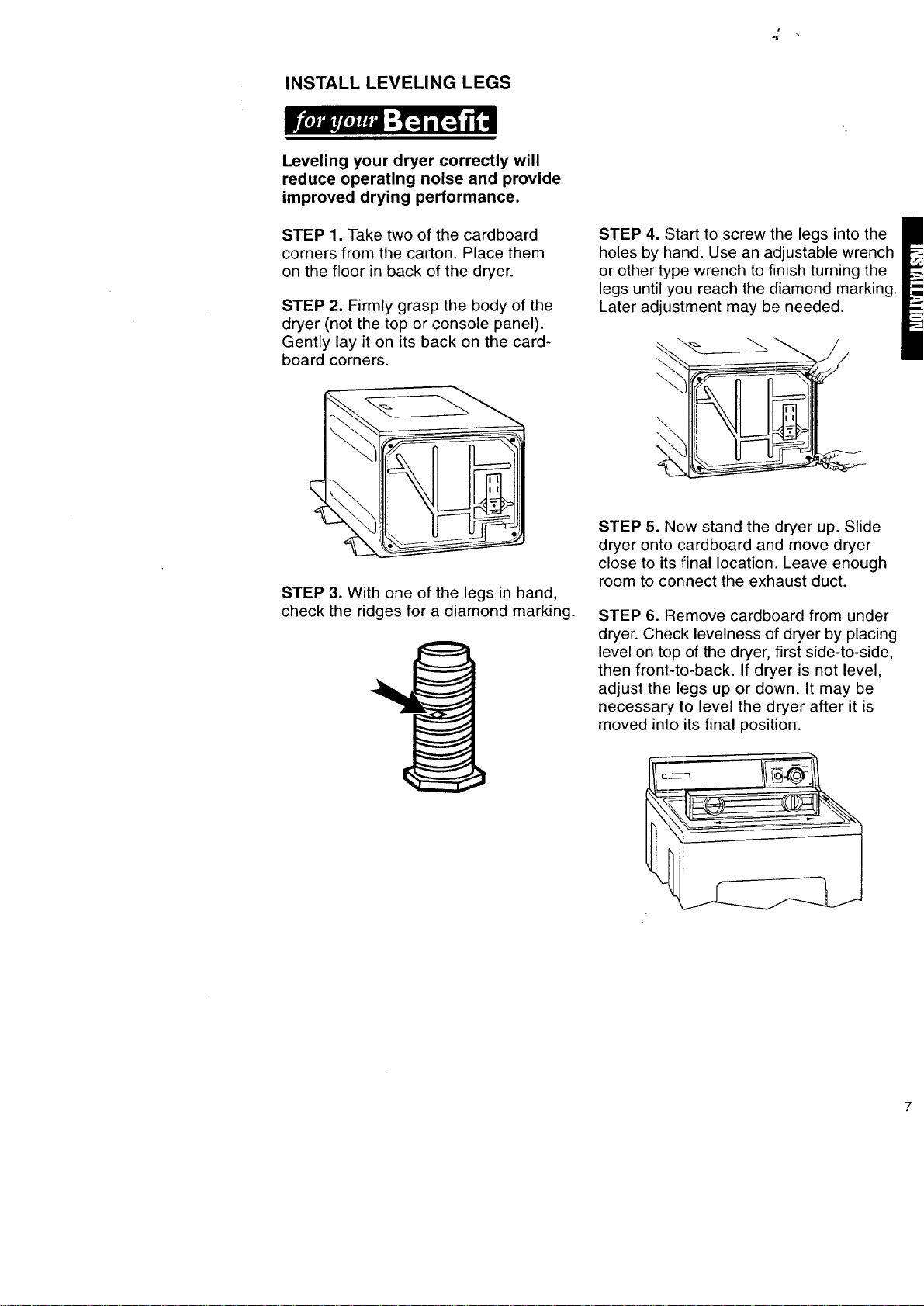
**4.8 .sq. in:..
mlrdmum
venlilation
area
• I I --H"'i
FRONTVIEW SIDEVIEW FRONTVIEW
(DOORNOTSHOWN) (DOORSHOWN) (ODORwITrHVENT)
3"
*'24 sq. in.
minimum- _:_,_:_:_1
._x_
ventilation 3"
area
MINIMUM INSTALLATIONSPACING,CLOSETINSTALLATIONM_R BEEXHAUSTED.
* ADDITIONALCLEARANCESFORWALL,DOORANDFLOORMOLDINGSMAYBEREQUIIRED.
** OPENINGIS MINIMUM FORCLOSETDOOR.LOUVEREDDOOR_ITH EQUIVALENTAIR
OPENINGSISACCEPTABLE.
*** ADDITIONALSPACEIS NEEDEDWHENEXTERNALEXHAUS'I"ELBOWIS USED.
• The installation spacing is in inches
and is the minimum allowable.
• Additional spacing should be
considered for ease of installation
and servicing.
• If closet door is installed, the
minimum air openings in top and
bottom are required.
• Louverecl doors with equivalent
air openings in top and bottom are
acceptable. Closet installation must
be exhausted. Other installations must
use at least the minimum dimensions
indicated.
• Additional space for other appliances
to be irTstalled in the area should be
considered.
INSTALL LEVELING LEGS
Leveling your dryer correctly will
reduce operating noise and provide
improved drying performance.
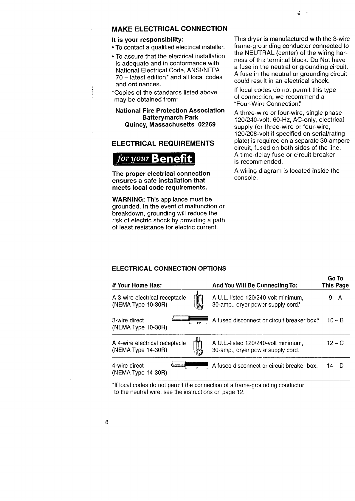
STEP 1. Take two of the cardboard
corners from the carton. Place them
on the floor in back of the dryer.
STEP 2. Firmly grasp the body of the
dryer (not the top or console panel).
Gently lay it on its back on the card-
board corners.
STEP 4. Start to screw the legs into the
holes by hand. Use an adjustable wrench
or other type wrench to finish turning the
legs until you reach the diamond marking.
Later adjustment may be needed.
\
\
\
\\
\
STEP 3. With one of the legs in hand,
check the ridges for a diamond marking.
STEP 5. Now stand the dryer up. Slide
dryer onto cardboard and move dryer
close to its final location. Leave enough
room to connect the exhaust duct.
STEP 6. Remove cardboarcl from under
dryer. Check levelness of dryer by placing
level on top of the dryer, first side-to-side,
then front-to-back. If dryer is not level,
adjust thE: legs up or down. It may be
necessary, Io level the dryer after it is
moved into its final position.
MAKE ELECTRICAL CONNECTION
It is your responsibility:
• To contact a qualified electrical installer.
• To assure that the electrical installation
is adequate and in conformance with
National Electrical Code, ANSI/NFPA
70 - latest edition* and all local codes
and ordinances.
*Copies of the standards listed above
may be obtained from:
National Fire Protection Association
Batterymarch Park
Quincy, Massachusetts 02269
ELECTRICAL REQUIREMENTS
The proper electrical connection
ensures a safe installation that
meets local code requirements.
WARNING: This appliance must be
grounded. In the event of malfunction or
breakdown, grounding will reduce the
risk of electric shock by providing a path
of least resistance for electric current.
This dryer is manufactured with the 3-wire
frame-grounding conductor conaected to
the NEUTRAL (center) of the wiring har-
ness of the terminal block. Do Not have
a fuse in tlqe neutral or grounding circuit.
A fuse in the neutral or grounding circuit
could result in an electrical shock.
If local codes do not permit this type
of conneciion, we recommend a
"Four-Wire Connection;'
A three-wire or four-wire, .,;ingle phase
120/240-volt, 60-Hz, AC-only, electrical
supply (or three-wire or four-wire,
120/208-volt if specified on serial/rating
plate) is required on a separate 30-ampere
circuit, fused on both sides of the line.
A time-delay fuse or c_ircuit breaker
is recommended.
A wiring diagram is located inside the
console.
ELECTRICAL CONNECTION OPTIONS
If Your Home Has:
A 3-wire electrical receptacle
(NEMA Type 10-30R)
And You Will Be Connecting To:
A U.L.-listed 120/240-volt minimurn,
30-amp., dryer power supply cord*
3-wire direct
(NEMA Type 10-30R)
GoTo
This Page
IL
A 4-wire electrical receptacle r_l
(NEMA Type 14-30R)
4-wire direct
(NEMA Type 14-30R)
9-A
A fused disconnect or circuit breaker box.* 10- B
A U.L.-listed 120/240-volt minimum,
30-amp., dryer power supply cord.
12-C
*If local codes do not permit the connection of a frame-grounding conductor
to the neutral wire, see the instructions on page 12.
A fused disconnect or circuit breaker box. 14 - D
A. MAKE THREE-WIRE
ELECTRICAL CONNECTION
TO RECEPTACLE
If using a 3-wire power cord:
Electrical Shock Hazard
Turn power supply off before
connecting cord.
Use a new 30-ampere power supply
cord.
Plug into a grounded outlet.
Failure to follow these instructions
can result in death, fire, or electrical
shock.
Local codes may permit the use of
a U.L.-listed, 120/240-volt minimum,
30-ampere, dryer power supply cord
kit (pigtail). Power supply cord should
be type SRD or SRDT and be at least
four feet long. The wires that connect
to the dryer must end with ring terminals
or spade terminals with upturned ends.
A 3/4"U.L.-listed strain relief must be
installed where the power supply cord
connects to the dryer. Do Not modify the
power supply cord plug. If it does not fit
the outlet, have a proper outlet installed
by a qualified electrician.
The power supply cord must have three,
No.-10 copper wires to match a three-
wire receptacle of NEMAType 10-30R.
Three-wire
receptacle
(10-30R)
Do Not use an extension cord with
this dryer.
Do Not conr_ect plug end of power
supply cord into a live receptacle before
connecting icower supply cord to dryer
terminal block.
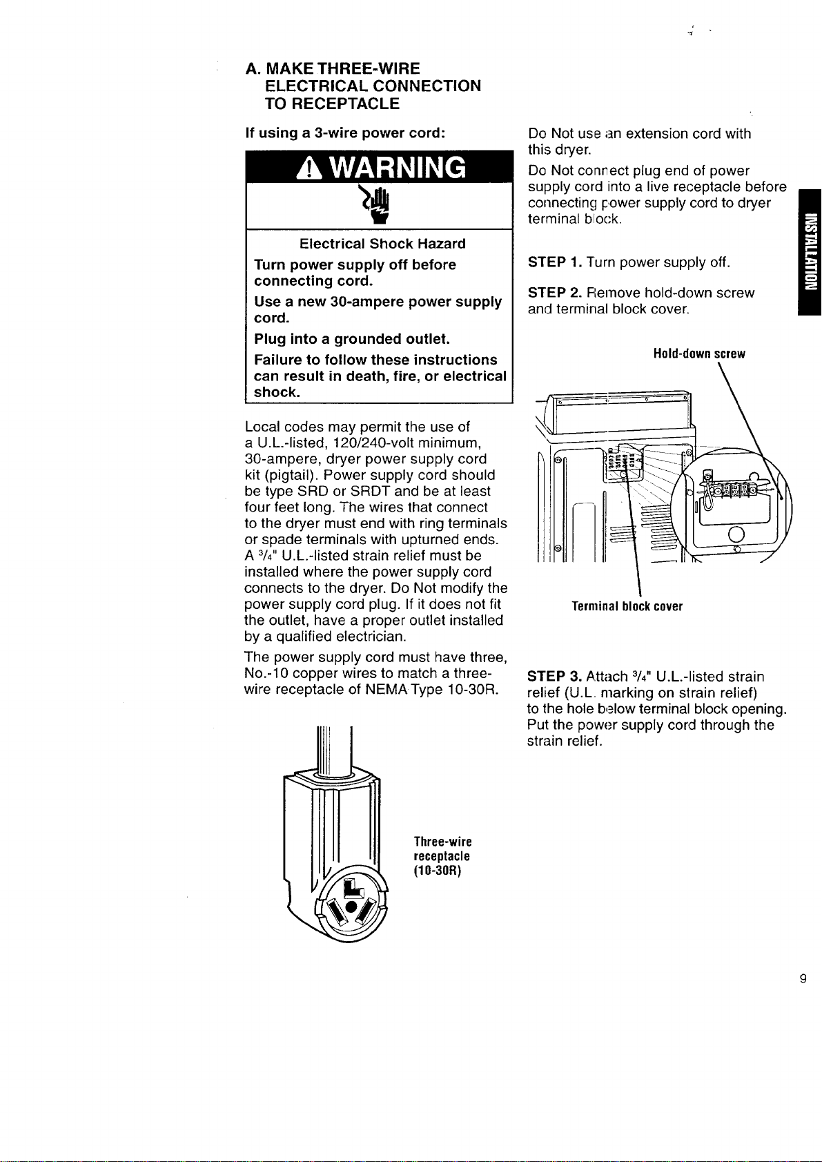
STEP 1. Turn power supply off.
STEP 2. FLemove hold-down screw
and terminal block cover.
Hold-downscrew
Terminalblockcover
STEP 3. ,_.ttach 3/4"U.L.-listed strain
relief (U.L. marking on strain relief)
to the hole b,_low terminal block opening.
Put the power supply cord through the
strain relief.
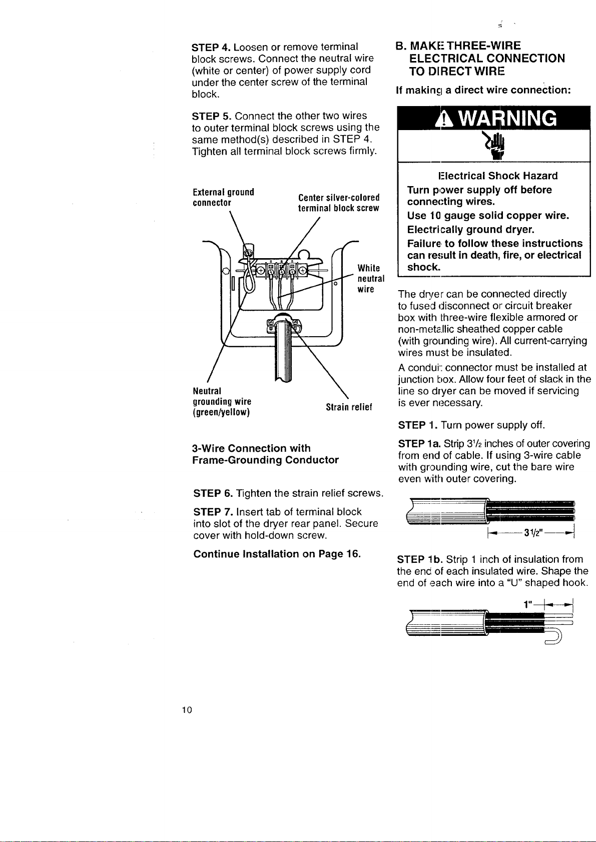
STEP4.Loosenorremoveterminal
blockscrews.Connecttheneutralwire.
(whiteorcenter)ofpowersupplycord
underthecenterscrewoftheterminal
block.
STEP5.Connecttheothertwowires
toouterterminalblockscrewsusingthe
samemethod(s)describedinSTEP4.
Tightenallterminalblockscrewsfirmly.
Externalground
connector
Centersilver-c010red
terminalblockscrew
White
neutral
wire
Neutral
groundingwire
(green/yellow)
Strainrelief
3-Wire Connection with
Frame-Grounding Conductor
STEP 6. Tighten the strain relief screws.
STEP 7. Insert tab of terminal block
into slot of the dryer rear panel. Secure
cover with hold-down screw.
Continue Installation on Page 16.
B. MAKE" THREE-WIRE
ELECTRICAL CONNECTION
TO DIRECT WlRI-
If makincl a direct wire connection:
I-lectrical Shock Hazard
Turn power supply off before
connecting wires.
Use 10 gauge solid copper wire.
Electrically ground dryer.
Failure, to follow these instructions
can result in death, fire, or electrical
shock.
The dq/er can be connected directly
to fused disconnect or circuit breaker
box with lhree-wire flexible armored or
non-met_.llic sheathed copper cable
(with grounding wire). All current-carrying
wires must be insulated.
A condui': connector must be installed at
junction box. Allow four feet of slack in the
line so dryer can be moved if servicing
is ever necessary.
STEP 1. Turn power supply off.
STEP la. Strip 31/2inches of outer covering
from end of cable. If using 3-wire cable
with grounding wire, cut the bare wire
even with outer covering.
r='l
t'/
!----
STEP 1b. Strip 1 inch of insulation from
the en_i of each insulated wire. Shape the
end of each wire into a "U" shaped hook.
10
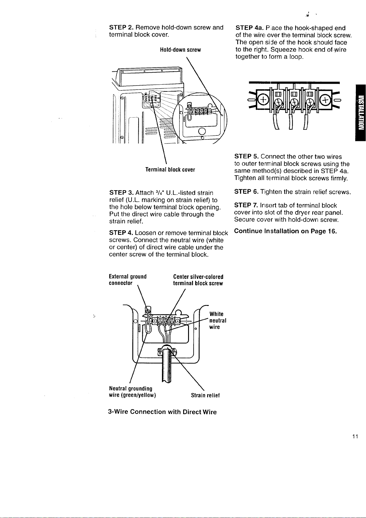
STEP 2. Remove hold-down screw and
terminal block cover.
Hold-downscrew
STEP 4a. Piace the hook-shaped end
of the wire over the terminal block screw.
The open siJe of the hook should face
to the right. Squeeze hook end of ,,wire
together to form a loop.
Terminalblockcover
STEP 3. Attach 3/4"U.L.-listed strain
relief (U.L. marking on strain relief) to
the hole below terminal block opening.
Put the direct wire cable through the
strain relief.
STEP 4. Loosen or remove terminal block
screws. Connect the neutral wire (white
or center) of direct wire cable under the
center screw of the terminal block.
STEP 5. Connect the other two wires
to outer terminal block screws using the
same method(s) described in STEP 4a.
Tighten all terminal block screws firmly.
STEP 6. Tighten the strain relief screws.
STEP 7. Insert tab of terminal block
cover into slot of the dryer rear panel.
Secure cover with hold-down screw.
Continue Installation on Page 16.
Externalground
connector
Centersilver-colored
terminalblockscrew
White
wire
Neutral grounding
wire (green/yellow)
Strain relief
3-Wire Connection with Direct Wire
11
ALTERNATE CONNECTION:
If local codes do NOT permit the
connection of a frame-grounding
conductor to the neutral wire:
Follow STEPS 1-7 for either Section A or
Section B with these required additions:
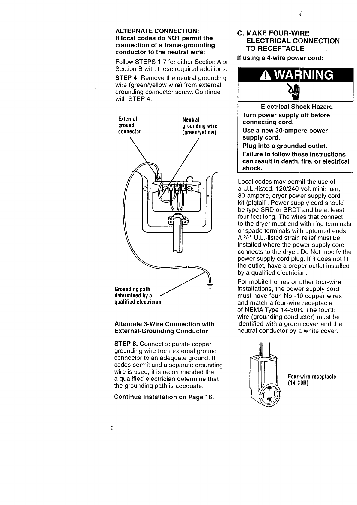
STEP 4. Remove the neutral grounding
wire (green/yellow wire) from external
grounding connector screw. Continue
with STEP 4.
External Neutral
ground groundingwire
connector (green/yellow)
Groundingpath
determined by a
qualified electrician
Alternate 3-Wire Connection with
External-Grounding Conductor
STEP 8. Connect separate copper
grounding wire from external ground
connector to an adequate ground. If
codes permit and a separate grounding
wire is used, it is recommended that
a qualified electrician determine that
the grounding path is adequate.
Continue Installation on Page 16.
C. MAKE FOUR-WIRE
ELECTRICAL CONNECTION
TO RI=-CEPTACLE
If using a 4-wire power cord:
Electrical Shock Hazard
Turn power supply off before
connec:ting cord.
Use a new 30-ampere power
supply cord.
Plug into a grounded outlet.
Failure to follow these instructions
can result in death, fire, or electrical
shock.
Local codes may permit the use of
a U.L.-lis':ed, 120/240-volt minimum,
30-ampere, dryer power supply cord
kit (pigtail). Power supply cord should
be type, SRD or SRDT and be at least
four feet long. The wires that connect
to the dryer must end with ring terminals
or spade terminals with upturned ends.
A 3/4"U.L.-listed strain relief must be
installed where the power supply cord
connects to the dryer. Do Not modify the
power supply cord plug. It"it does not fit
the outlet, have a proper outlet installed
by a qualified electrician.
For mobiqe homes or other four-wire
installations, the power supply cord
must have four, No.-10 copper wires
and m_Ltch a four-wire receptacle
of NEMA Type 14-30R. The fourth
wire (grounding conductor) must be
identified with a green cover and the
neutral conductor by a white cover.
F0ur-wirereceptacle
(14-30R)
12
Do Not use an extension cord with
this dryer.
Do Not connect plug end of power sup-
ply cord into a live receptacle before
connecting power supply cord to dryer
terminal block.
STEP 1. Tum power supply off.
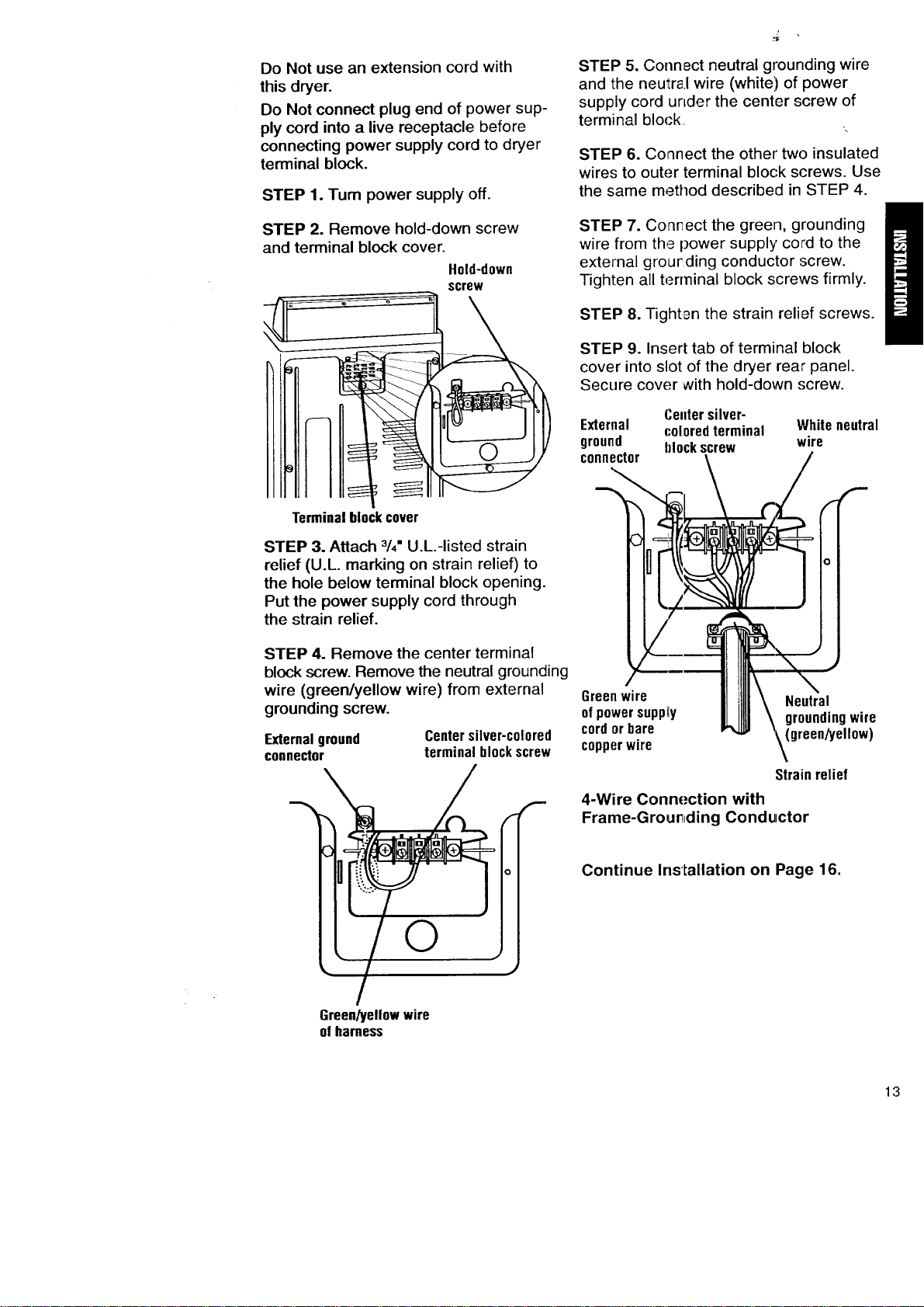
STEP 2. Remove hold-down screw
and terminal block cover.
Hold-down
screw
Terminalblockcover
STEP 3. Attach 3/4"U.L.-listed strain
relief (U.L. marking on strain relief) to
the hole below terminal block opening.
Put the power supply cord through
the strain relief.
STEP 4. Remove the center terminal
block screw. Remove the neutral grounding
wire (green/yellow wire) from external
grounding screw.
External ground
connector
Centersilver-colored
terminalblockscrew
©
STEP 5. Connect neutral grounding wire
and the neutra.I wire (white'.) of power
supply cord urLder the center screw of
terminal block
STEP 6. Co_nnect the other two insulated
wires to outer terminal block screws. Use
the same method described in STEP 4.
STEP 7. Conr_ect the green, grounding
wire from the power supply cord to the
external grourding conductor :screw.
Tighten all terminal block screws firmly.
STEP 8. Tighten the strain relief screws.
STEP 9. Insert tab of terminal block
cover into slot of the dryer rear panel.
Secure cover with hold-down .';crew.
Centersilver-
External coloredterminal Whiteneutral
ground hlockscrew wire
connector
Greenwire
ofpowersupply
cordorbare
copperwire
!
(...-
0
Strainrelief
4-Wire Connection with
Frame-Grour_ding Conductor
Continue Installation on Page 16.
Green/yellowwire
ofharness
13

D. MAKE FOUR-WIRE
ELECTRICAL CONNECTION
TO DIRECT WIRE
If making a direct wire connection:
Electrical Shock Hazard
Turn power supply off before
connecting wires.
Use 10 gauge solid copper wire.
Electrically ground dryer.
Failure to follow these instructions
can result in death, fire, or electrical
shock.
The dryer can be connected directly
to fused disconnect or circuit breaker
box with four-wire flexible armored or
non-metallic sheathed copper cable
(with grounding wire). All current-carrying
wires must be insulated.
A conduit connector must be installed
at junction box. Allow four feet of slack
in the line so dryer can be moved if
servicing is ever necessary.
STEP 1. Turn power supply off.
STEP la. Strip 5 inches of outer covering
from end of cable. Leave bare grounding
wire at 5 inches.
i_ 5" _-_
I--
STEP lb. Strip 11/2inches from
3 remaining insulated wires. Strip
insulation back 1 inch. Shape the end
of each wire into a "U" shaped hook.
?
STEP 2. Remove hold-down screw
and terrninal block cover.
Hold-down
screw
Terminalblockcover
STEP 3. Attach 3/4"U.L.-listed strain
relief (U.L. marking on strain relief) to
the hole below terminal block opening.
Put the direct wire cable through the
strain relief.
STEP 4. Remove the center terminal
block ,,screw.Remove the neutral grounding
wire (!green/yellow wire) from external
grounding screw.
External !lr0und
connectol
Centersilver-colored
terminalblockscrew
r
6reen/yellow wire
cf harness
14
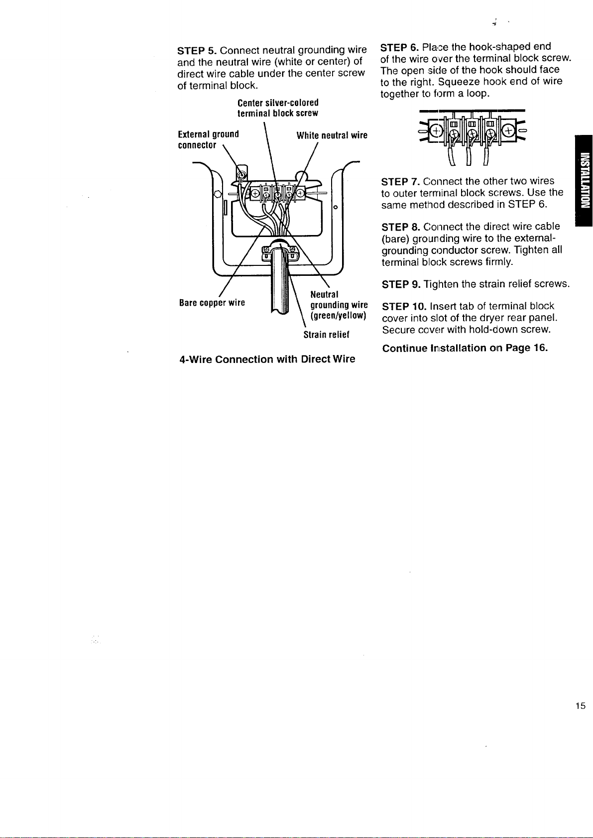
STEP 5. Connect neutral grounding wire
and the neutral wire (white or center) of
direct wire cable under the center screw
of terminal block.
Centersilver-colored
terminalblockscrew
Externalground
connector
Whiteneutralwire
Barecopperwire
Neutral
groundingwire
(green/yellow)
Strain relief
4-Wire Connection with Direct Wire
STEP 6. Place the hook-shaped end
of the wire over the terminal block screw.
The open _sideof the hook should face
to the right. Squeeze hook end of wire
together to form a loop.
STEP 7. Connect the other two wires
to outer terminal block screws. Use the
same method described in STEP 6.
STEP 8. Connect the direct wire cable
(bare) grounding wire to the external-
grounding conductor screw. Tighten all
terminal block screws firmly.
STEP 9. Tighten the strain relief screws.
STEP 10. Insert tab of terminal block
cover into slot of the dryer rear panel.
Secure cover with hold-down screw.
Continue Ir_stallation on Page 16.
<.
15
CONNECT EXHAUST
, Replace plastic exhaust duct with
rigid metal or flexible metal duct.
• If using an existing exhaust system,
clean lint from entire length of exhaust
system. Make sure exhaust hood is
not plugged with lint.
A properly exhausted dryer will give
you the shortest drying time, lower
your utility bill and extend the life of
the dryer.
Typical installations
for rear exhausting -
straight
(see pgs. 18-19)
Avoid pushing the dryer tightly against
a wall. This can crush or kink the duct.
Use the straightest path you can, where
possible, to avoid 90 ° turns.
Fire Hazard
Use a heavy metal vent.
Do not use a plastic vent.
Do not use a metal foil vent.
Failure to do so can result in death
or fire.
• Do Not use non-metal flexible duct,
metal duct that is smaller than four
inches in diameter or exhaust hoods
with magnetic latches.
• Do Not exhaust dryer into a chimney,
furnace cold air duct, attic or crawl space,
or any other duct used for venting.
• Do Not install flexible duct in enclosed
walls, ceilings or floors.
Typical installations exhaust from the
rear of the dryer.
Typical installations _
for rear exhausting -
offset
(see pgs. 16-18) | I ___L___]
_[
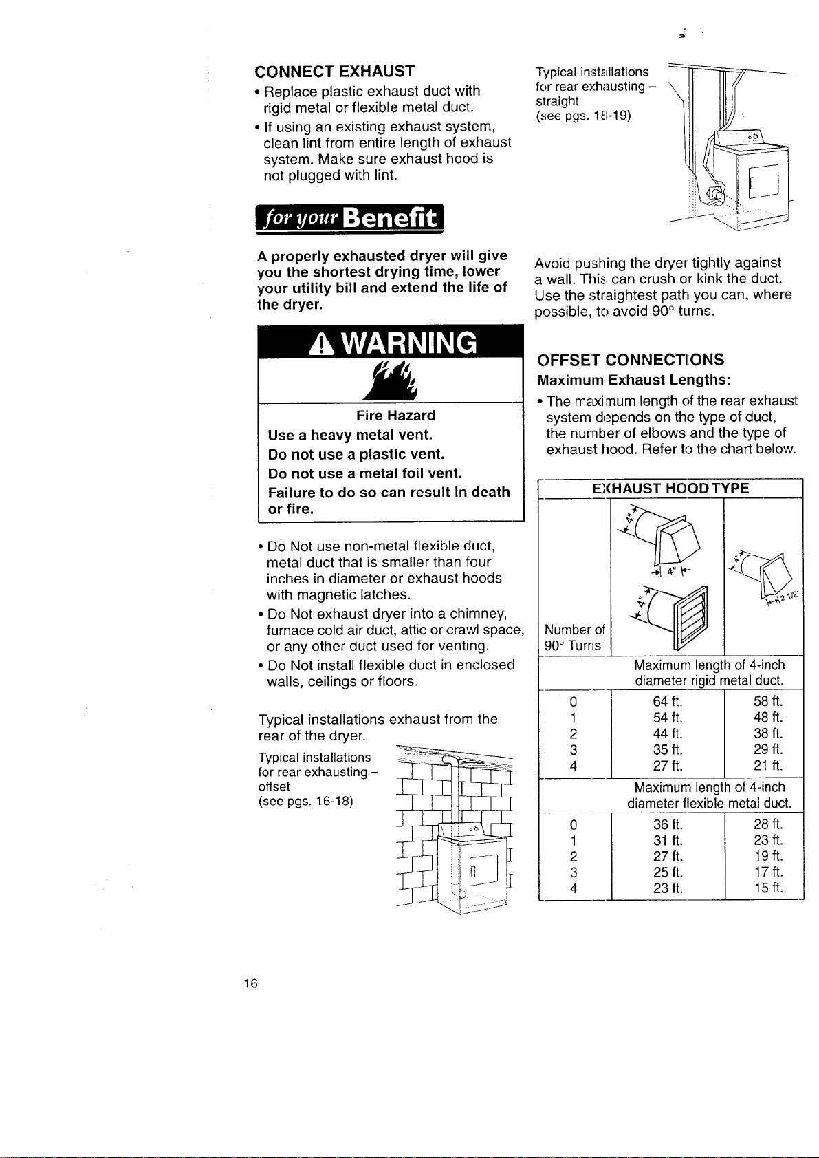
OFFSET CONNECTIIONS
Maximum Exhaust Lengths:
• The m&xi mum length of the rear exhaust
system depends on the type of duct,
the number of elbows and the type of
exhaust hood. Refer to the chart below.
EXHAUST HOOD TYPE
Number of
90° Turns
0
1
2
3
4
Maximum length of 4-inch
diameter rigid metal duct.
64 ft. 58 ft.
54 ft. 48 ft.
44 ft. 38 ft.
35 ft. 29 ft.
27ft. 21 ft.
0
1
2
3
4
Maximum length of 4-inch
diameter flexible metal duct.
36 ft. 28 ft.
31 ft. 23 ft.
27 ft. 19 ft.
25ft. 17ft.
23 ft. 15 ft.
16
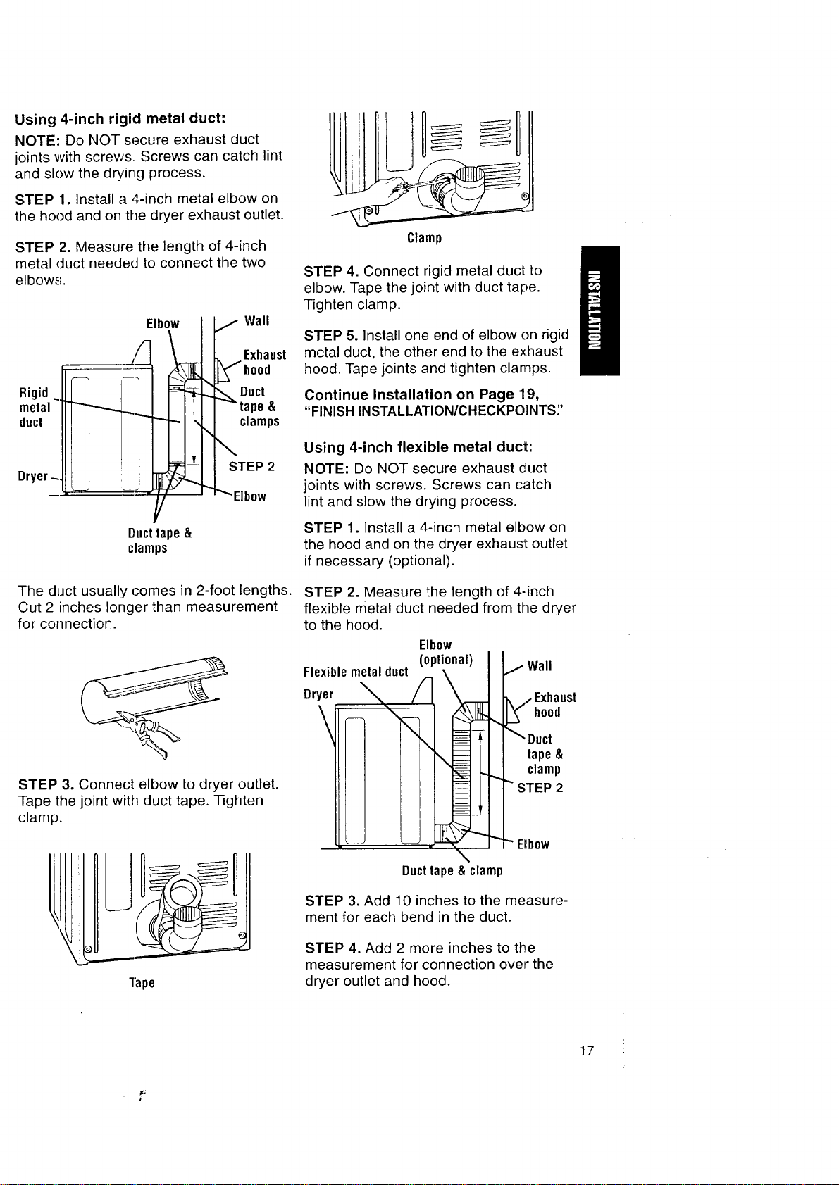
Using 4-inch rigid metal duct:
NOTE: Do NOT secure exhaust duct
joints with screws. Screws can catch lint
and slow the drying process.
STEP 1. Install a 4-inch metal elbow on
the hood and on the dryer exhaust outlet.
STEP 2. Measure the length of 4-inch
metal duct needed to connect the two
elbows.
Rigid~
metal
duct
Dryer-
The duct usually comes in 2-foot lengths.
Cut 2 inches longer than measurement
for connection.
STEP 3. Connect elbow to dryer outlet.
Tape the joint with duct tape. Tighten
clamp.
Tape
IlllljU
Clamp
STEP 4. Connect rigid metal duct to
elbow. Tape the joint with duct tape.
Tighten clamp.
STEP 5. Install one end of elbow on rigid
metal duct, the other end to the exhaust
hood. Tape joints and tighten clamps.
Continue Installation on Page 19,
"FINISH INSTALLATION/CH ECKPOINTS;'
Using 4-inch flexible metal duct:
NOTE: Do NOT secure exhaust duct
joints with screws. Screws can catch
lint and slow the drying process.
STEP 1. Install a 4-inch metal elbow on
the hood and on the dryer exhaust outlet
if necessary (optional).
STEP 2. Measure the length of 4-inch
flexible metal duct needed from the dryer
to the hood.
Elbow
(optional)
\
\
L •
j Wall
.,,, Exhaust
.__ hood
_Duct
tape&
clamp
""STEP 2
Elbow
\
Duct tape & clamp
STEP 3. Add 10 inches to the measure-
ment for each bend in the duct.
STEP 4. Add 2 more inches to the
measurement for connection over the
dryer outlet and hood.
17
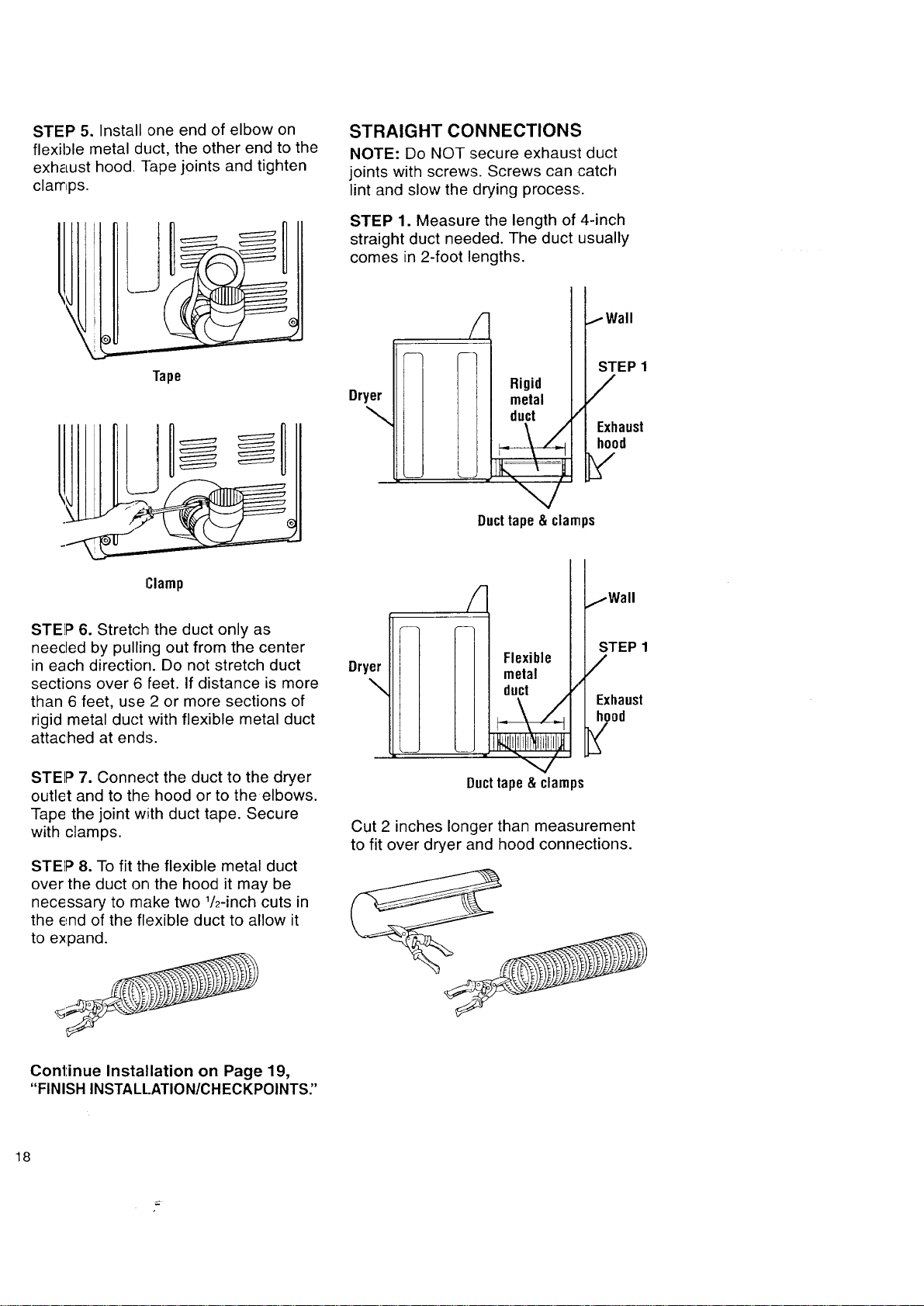
STEP 5. Install one end of elbow on
flexible metal duct, the other end to the
exhaust hood Tape joints and tighten
clamps.
I
Tape
Clamp
STEP 6. Stretch the duct only as
needed by pulling out from the center
in each direction. Do not stretch duct
sections over 6 feet. If distance is more
than 6 feet, use 2 or more sections of
rigid metal duct with flexible metal duct
attached at ends.
STEP 7. Connect the duct to the dryer
outlet and to the hood or to the elbows.
Tape the joint with duct tape. Secure
with clamps.
STEP 8. To fit the flexible metal duct
over the duct on the hood it may be
necessary to make two 1/2-inch cuts in
the end of the flexible duct to allow it
to expand.
STRAIGHT CONNECTIONS
NOTE: Do NOT secure exhaust duct
joints with screws. Screws can catch
lint and slow the drying process.
STEP 1. Measure the length of 4-inch
straight duct needed. The duct usually
comes in 2-foot lengths.
Dryer
\
Rigid
metal
duct
/
IWall
STEP 1
/
Exhaust
hood
Ducttape&clamps
Dryer
\
Flexible
metal
duct /
_\Z
Ducttape&clamps
jWall
STEP 1
/
Exhaust
Cut 2 inches longer than measurement
to fit over dryer and hood connections.
Continue Installation on Page 19,
"FINISH INSTALL.ATION/CHECKPOINTS"
18
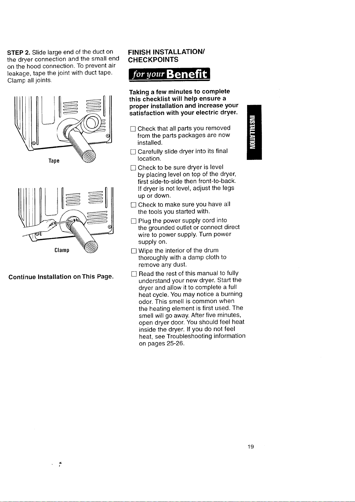
STEP 2. Slide large end of the duct on
the dQ/er connection and the small end
on the hood connection. To prevent air
leakacle, tape the joint with duct tape.
Clamp all joints.
Tape
J
Continue Installation on This Page.
FINISH INSTALLATION/
CHECKPOINTS
Taking a few minutes to complete
this checklist will help ensure a
proper installation and increase your
satisfaction with your electric dryer.
[]
[]
[]
[]
[]
[]
[]
Check that all parts you removed
from the parts packages are now
installed.
Carefully slide dryer into its final
location.
Check to be sure dryer is level
by placing level on top of the dryer,
first side-to-side then front-to-back.
If dryer is not level, adjust the legs
up or down.
Check to make sure you have all
the tools you started with.
Plug the power supply cord into
the grounded outlet or connect direct
wire to power supply. Turn power
supply on.
Wipe the interior of the drum
thoroughly with a damp cloth to
remove any dust.
Read the rest of this manual to fully
understand your new dryer. Start the
dryer and allow it to complete a full
heat cycle. You may notice a burning
odor. This smell is common when
the heating element is first used. The
smell will go away. After five minutes,
open dryer door. You should feel heat
inside the dryer. If you do not feel
heat, see Troubleshooting information
on pages 25-26.
19
STARTING YOUR DRYER
Explosion Hazard
Never place items in the dryer that
are dampened with gasoline or other
flammable fluids.
Do not wash or dry items soiled with
vegetable or cooking oils because
they may contain some oil after
laundering.
Doing so can result in death,
explosion, or fire.
To get the best drying results, you must
operate your dryer properly. This section
gives you this important information.
Page references are included for more
information. You can also refer to the
"Feature Sheet" supplied with your dryer.
STEP 1. Check lint screen. Clean
if needed.
STEP 2. Put laundry into dryer and
shut door.
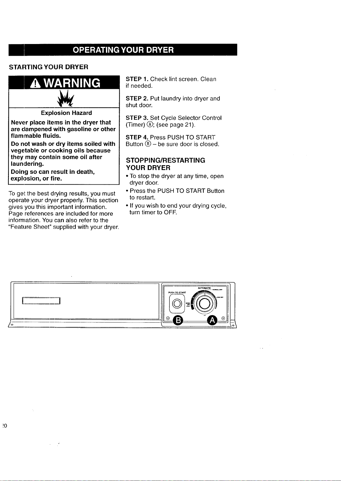
STEP 3. Set Cycle Selector Control
(Timer) (_); (see page 21).
STEP 4. Press PUSH TO START
Button O - be sure door is closed.
STOPPING/RESTARTING
YOUR DRYER
• To stop the dryer at any time, open
dryer door.
• Press the PUSH TO START Button
to restart.
• If you wish to end your drying cycle,
turn timer to OFF.
I ]
CYCLE DESCRIPTION
Fire Hazard
Line dry heat-sensitive fabrics such
as rubber and plastic.
Do not use heat to dry these items.
Failure to follow these instructions
can result in death or fire.
The AUTOMATIC Cycle saves you time
by providing the best drying results
in the shortest time.This can help
you save money on utility bills and
reduce the risk of fabric damage.
AUTOlVlATIC CYCLE
Use this cycle for sturdy clothes or syn-
thetic, permanent press items. Clothes
are dried at high heat. When the dryness
selected is reached, the dryer goes into
a 5-minute (approx.) cool down period.
• Set the Cycle Selector Control to
NORMAL DRY(*) which is good for
most fabrics.
• At the end of the cycle, feel the dried
clothes. If they are damp, move dial
towards MORE DRY the next time you
do a similar load. If they are overdried,
move dial towards LESS DRY the next
time you do a similar load.
• Dryness is determined by thermostats
that react to the amount of moisture
in the air exhausted from the dryer.
Moist air indicates clothes are still
damp, dry air indicates that moisture
has been removed.
COOL DOWN
Approximately five minutes before the
end of the AUTOMATIC Cycle, clothes
are tumbled without heat to help reduce
wrinkles and make clothes more com-
fortable to handle.
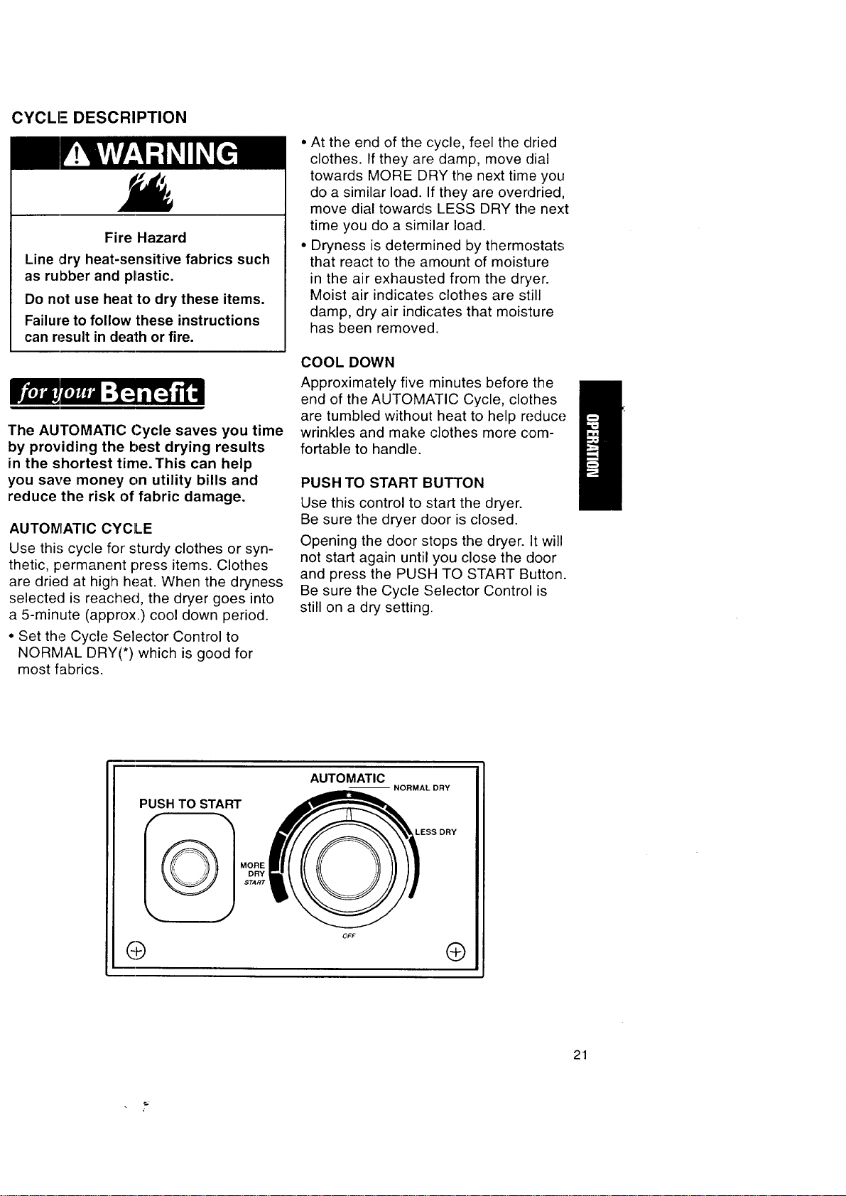
PUSH TO START BUTTON
Use this control to start the dryer.
Be sure the dryer door is closed.
Opening the door stops the dryer. It will
not start again until you close the door
and press the PUSH TO START Button.
Be sure the Cycle Selector Control is
still on a dry setting.
PUSH TO START
I_ MORE
DRY
START
O
AUTOMATIC
--NORMAL DRY
LESS DRY
®
21
This section explains how to care for
your dryer properly and safely.
I
Proper care of your dryer can extend
its life and help you avoid costly
service calls.
EXTERIOR
Use a soft, damp cloth to clean the
cabi_net. Avoid using harsh abrasives.
Do not put sharp metal objects on or in
your dryer. They can damage the finish.
INTI-RIOR
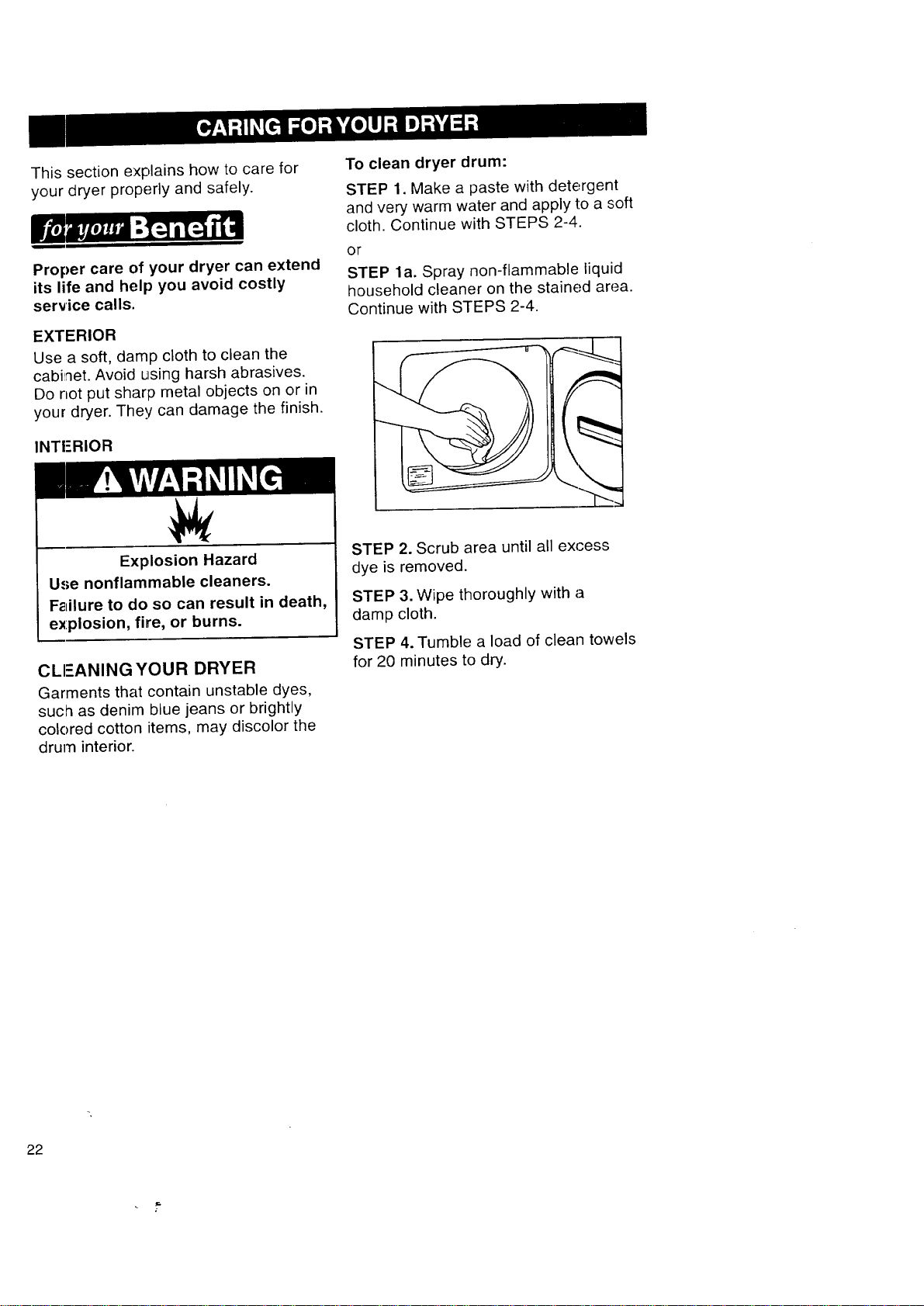
To clean dryer drum:
STEP 1. Make a paste with detergent
and very warm water and apply to a soft
cloth. Continue with STEPS 2-4.
OF
STEP la. Spray non-flammable liquid
household cleaner on the stained area.
Continue with STEPS 2-4.
Explosion Hazard
Use nonflammable cleaners.
Failure to do so can result in death,
explosion, fire, or burns.
CLEANING YOUR DRYER
Garments that contain unstable dyes,
such as denim blue jeans or brightly
colored cotton items, may discolor the
drum interior.
STEP 2. Scrub area until all excess
dye is removed.
STEP 3. Wipe thoroughly with a
damp cloth.
STEP 4. Tumble a load of clean towels
for 20 minutes to dry.
22
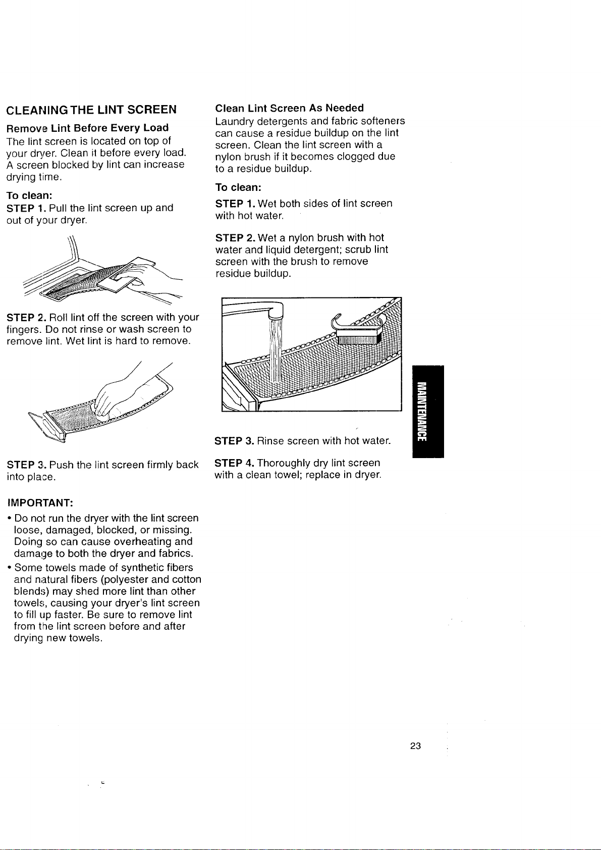
CLEANING THE LINT SCREEN
Remove Lint Before Every Load
The lint screen is located on top of
your dryer. Clean ii before every load.
A screen blocked by lint can increase
drying time.
To clean:
STEP 1. Pull the lint screen up and
out of your dryer.
Clean Lint Screen As Needed
Laundry detergents and fabric softeners
can cause a residue buildup on the lint
screen. Clean the lint screen with a
nylon brush if it becomes clogged due
to a residue buildup.
To clean:
STEP 1. Wet both sides of lint screen
with hot water.
STEP 2. Wet a nylon brush with hot
water and liquid detergent; scrub lint
screen with the brush to remove
residue buildup.
STEP 2:.Roll lint off the screen with your
fingers. Do not rinse or wash screen to
remove lint. Wet lint is hard to remove.
STEP 3;.Push the lint screen firmly back
into place.
IMPORTANT:
• Do not run the dryer with the lint screen
loose, damaged, blocked, or missing.
Doing so can cause overheating and
damage to both the dryer and fabrics.
• Some towels made of synthetic fibers
and natural fibers (polyester and cotton
blends) may shed more lint than other
towels, causing your dryer's lint screen
to fill up faster. Be sure to remove lint
from the lint screen before and after
drying new towels.
STEP 3. Rinse screen with hot water.
STEP 4. Thoroughly dry lint screen
with a clean towel; replace in dryer.
23
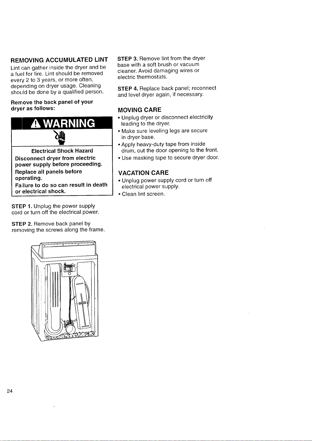
REMOVING ACCUMULATED LINT
Lint can gather inside the dryer and be
a fuel for fire. Lint should be removed
every 2 to 3 years, or more often,
depending on dryer usage. Cleaning
should be done by a qualified person.
Remove the back panel of your
dryer as follows:
Electrical Shock Hazard
Disconnect dryer from electric
power supply before proceeding.
Replace all panels before
operating.
Failure to do so can result in death
or electrical shock.
STEP 1. Unplug the power supply
cord or turn off the electrical power.
STEP 2. Remove back panel by
removing the screws along the frame.
STEP 3. Remove lint from the dryer
base with a soft brush or vacuum
cleaner. Avoid damaging wires or
electric thermostats.
STEP 4. Replace back panel; reconnect
and level dryer again, if necessary.
MOVING CARE
• Unplug dryer or disconnect electricity
leading to the dryer.
• Make sure leveling legs are secure
in dryer base.
• Apply heavy-duty tape from inside
drum, out the door opening to the front.
• Use masking tape to secure dryer door.
VACATION CARE
• Unplug power supply cord or turn off
electrical power supply.
• Clean lint screen.
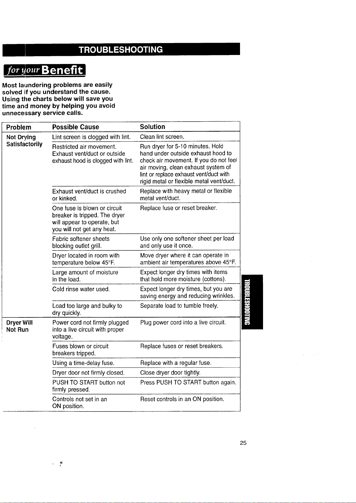
Most laundering problems are easily
solved if you understand the cause.
Using the charts below will save you
time and money by helping you avoid
unnecessary service calls.
Problem Possible Cause Solution
Not Dq!ing Lint screen is clogged with lint. Clean lint screen.
Satisfactorily Restricted air movement.
Exhaust vent/duct or outside
exhaust hood is clogged with lint.
Run dryer for 5-10 minutes. Hold
hand under outside exhaust hood to
check air movement. If you do not feel
air moving, clean exhaust system of
lint or replace exhaust vent/duct with
rigid metal or flexible metal vent/duct.
Exhaust vent/duct is crushed Replace with heavy metal or flexible
or kinked, metal vent/duct.
One fuse is blown or circuit Replace fuse or reset breaker.
breaker is tripped. The dryer
will appear to operate, but
you will not get any heat.
Fabric softener sheets Use only one softener sheet per load
blocking outlet grill, and only use it once.
Dryer located in room with Move dryer where it can operate in
temperature below 45°E ambient air temperatures above 45°E
Large amount of moisture Expect longer dry times with items
in the load. that hold more moisture (cottons).
C,old rinse water used. Expect longer dry times, but you are
saving energy and reducing wrinkles.
Load too large and bulky to Separate load to tumble freely.
dry quickly.
Dryer Will Power cord not firmly plugged Plug power cord into a live circuit.
Not Run into a live circuit with proper
voltage.
Fuses blown or circuit Replace fuses or reset breakers.
breakers tripped.
Using a time-delay fuse. Replace with a regular fuse.
Dryer door not firmly closed. Close dryer door tightly.
PUSH TO START button not Press PUSH TO START button again.
firmly pressed.
Controls not set in an Reset controls in an ON position.
ON position.
25
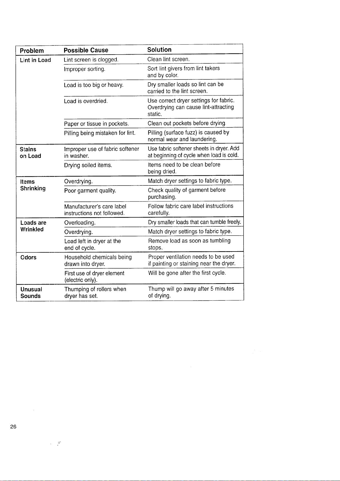
Problem Possible Cause Solution
Lint in Load Lint screen is clogged. Clean lint screen.
Improper sorting. Sort lint givers from lint takers
and by color.
Load is too big or heavy. Dry smaller loads so lint can be
carried to the lint screen.
Load is overdried. Use correct dryer settings for fabric.
Overdrying can cause lint-attracting
static.
Paper or tissue in pockets. Clean out pockets before drying,
Pilling being mistaken for lint. Pilling (surface fuzz) is caused by
normal wear and laundering.
Stains Improper use of fabric softener Use fabric softener sheets in dryer. Add
on Load in washer, at beginning of cycle when load iscold.
Drying soiled items. Items need to be clean before
being dried.
Items Overdrying. Match dryer settings to fabric type.
Shrinking Poor garment quality. Check quality of garment before
purchasing.
Manufacturer's care label Follow fabric care label instructions
instructions not followed, carefully.
Loads are Overloading. Dry smaller loads that can tumble freely.
Wrinkled Overdrying. Match dryer settings to fabric type.
Load left in dryer at the Remove load as soon as tumbling
end of cycle, stops.
Odors Household chemicals being Proper ventilation needs to,be used
drawn into dryer, if painting or staining near the dryer.
First use of dryer element Will be gone after the first cycle.
(electric only).
Unusual Thumping of rollers when Thump will go away after 5;minutes
Sounds dryer has set. of drying.
26
ELECTRIC DRYERS
We Service What We Sell
"We Service What 'We Sell" is our
assurance you can depend on Sears
for service. Your Electric Dryer has
added value when you consider that
Sears has service units nationwide,
staffed with professional technicians
specifically trained on Sears appliances
and having the parts, tools, and equip-
ment to ensure that we meet our pledge
to you..."We Service What We Sell'.'
Sears Maintenance Agreement
Maintain the value of your Electric Dryer
with a Sears Maintenance Agreement.
Sears Electric Dryers are designed,
manufactured, and tested for years of
dependable operatiion. Yet, any modern
appliance may require service from
time to time.
The Sears Maintenance Agreement
• Is your way to buy tomorrow's service
at today's prices.
• Eliminates repair bills resulting from
normal use.
• Allows for as many service calls as
required.
• Provides for service by professional
Sears Trained Technicians.
• Even if you don't need repairs, the
Maintenance Agreement offers an
annual preventative maintenance
check-up at your request!
This maintenance agreement does not
cover original installation, reinstallation,
or damage resulting from external
causes such as acts of abuse, theft,
fire, flood, wind, lightning, freezing,
power failure, power reduction, etc.
\
27
Fonrtherepairorreplacementpartsyou
needdelivereddirectlytoyourhome
Call7 am- 7 pm,7 daysaweek
1,-8OO-366-PART
(1-,800-366-1278)
Forin-homemajorbrandrepairservice
Call24hoursaday,7 daysaweek
1-800-4-REPAIR
{1-800-473-7247)
Forthelocationofa SearsPartsand
RepairCenterinyourarea
Call24hoursa day,7 daysaweek
1-800-448-1 222
Forinlormationonpurchasinga Sears
MaintenanceAgreementortoinquire
aboutanexistingAgreement
Call9 am -[5 pm,Monday- Saturday
1-800-827-6655
Whenrequestingserviceorordering
parts,alwaysgivethefollowing
information:
• ProductType • PartNumber
• ModelNumber • PartDescription
@ ARS
28
America'sRepairSpecialists