Loading ...
Loading ...
Loading ...
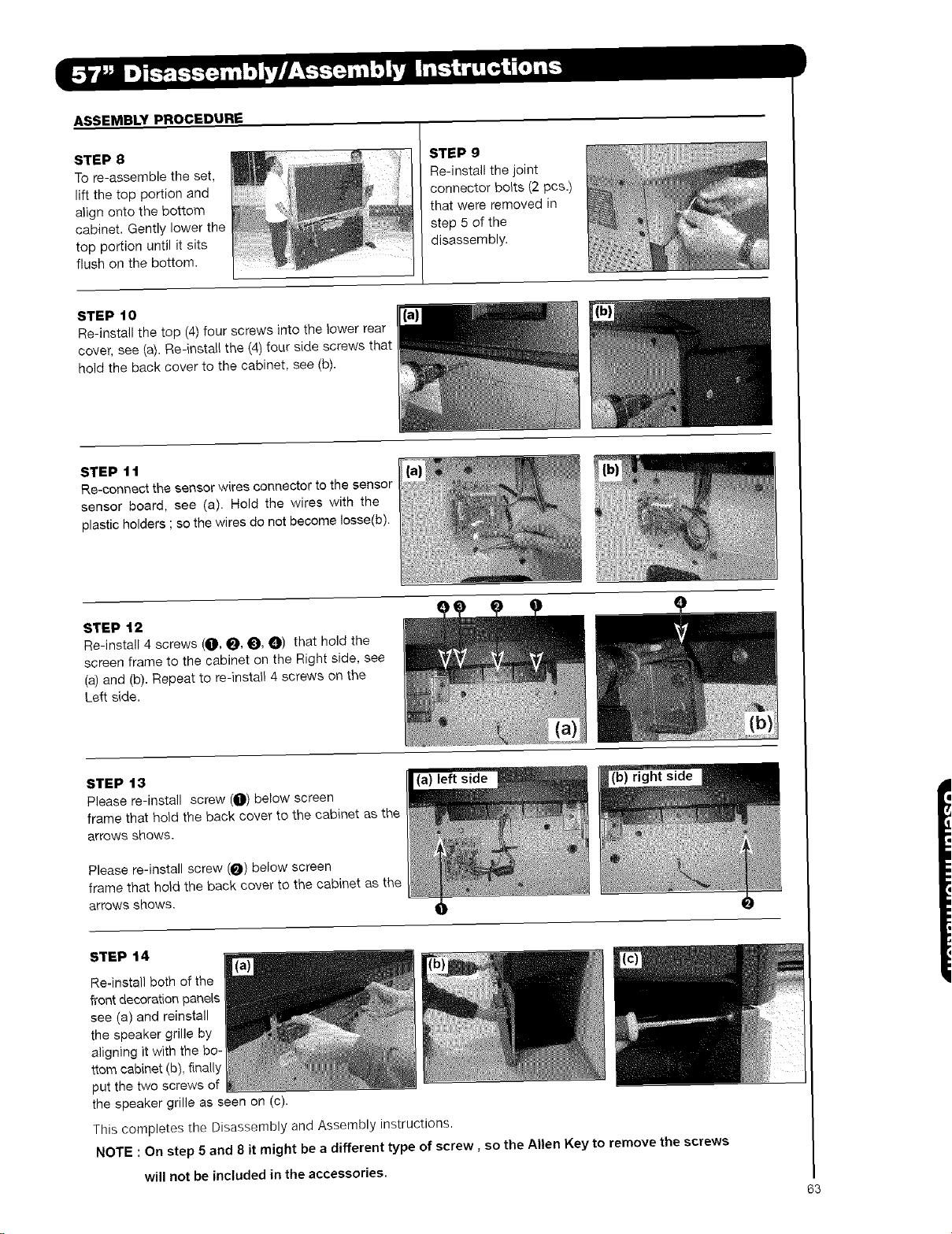
ASSEMBLY PROCEDURE
STEP 8
To re-assemble the set,
lift the top portion and
align onto the bottom
cabinet. Gently lower the
top portion until it sits
flush on the bottom.
STEP 9
Re-install the joint
connector bolts (2 pcs.)
that were removed in
step 5 of the
disassembly.
STEP t0
Re-install the top (4) four screws into the }ower rear
cover, see (a}. Re-instal{ the (4) four side screws that
hold the back cover to the cabinet, see (b).
STEP 11
Re-connect the sensor wires connector to the sensor
sensor board, see (a). Hold the wires with the
plastic holders ; so the wires do not become Iosse(b).
STEP 12
Re-install 4 screws (O, _, 0, 0) that hold the
screen frame to the cabinet on the Right side, see
(a) and (b). Repeat to re-install 4 screws on the
Left side.
STEP 13
Please re-install screw (O) below screen
frame that hold the back cover to the cabinet as the
arrows shows.
Please re-install screw (_) below screen
frame that hold the back cover to the cabinet as the
arrows shows.
right side
STEP 14
Re-install both of the
front decoration panels
see (a) and reinstall
the speaker grille by
aligning it with the bo-
ttom cabinet (b), finally
put the two screws of
the speaker grille as seen on (c).
This completes the Disassembly and Assembly instructions.
NOTE : On step 5 and 8 it might be a different type of screw, so the Allen Key to remove the screws
will not be included in the accessories.
63
Loading ...
Loading ...
Loading ...