Loading ...
Loading ...
Loading ...

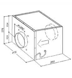
SEM2(g.9)
Warning!Theremotettedexhaustinggroup(externalmotor)isbuiltinclassIplate,the-
reforeitneedstheearthconnection.
The appliance was designed to exhaust odours and vapours in the best way. The appliance is
to be installed on the outside wall of the house and connetted to the cooker-hood which is in
the kitchen (g. 10)
Installation: the mounting of the appliance is to be made by qualied technicians. Using the
appropriate drilling jig (g. 11) drill all the holes marked on it into the external wall, by paying
attention not to damage water pipes or power lines.
Theholesonthewallaretobedrilledwitha8mm.bit.Insert,stepbystep,thefollowing
partsintheholesdrilled:
- the corresponding plastic dowels supplied (g. 11A)
- the two telescopic pipes in the hole of 160 mm.
- the plastic pipe of 40 mm. diameter.
Before leaning the appliance against the wall, insert the supply cord in the plastic pipe. Fix the
appliance without the stainless steel external body, which was previously removed from the
motor block, by matching the holes of the motor block with the holes on the wall. Tighten with
the screws supplied (g.11B).
Connectionofthepipes: the appliance is endowed with an air entrance to be connected with
the telescopic pipes and an air outlet.
After xing the appliance on the external wall, connect the two telescopic pipes, which are pla-
ced inside the wall, with the cooker-hood through the exible pipes (g. 12).
The xing between the pipes have to be made with appropriate metal clamps (pipes and clamps
are supplied by the installer).
Electricalconnectiontothehood:
the unit is supplied with a pipe 7 meters long. After having let the cable pass through the plastic
pipe (g. 12E) placed in the wall (g. 12D), placed it closed to the unit and connect the 6 poles
connector (Fig. 12E) and the 2 poles connector (Fig. 12G).
In order to avoid water inltrations, please apply silicone on the product perimeter, close to
the wall.
Installationofthestainlesssteelexternalbody: put the stainless steel body again, by ma-
tching the air exhausting grid with the air outlet of the motor block (g. 13).
6
Loading ...
Loading ...
Loading ...