Loading ...
Loading ...
Loading ...
13
1a
2
5
1
4
2
OK
OK
OK
OK
OK
OK
OK
OK
OK
OK
OK
OK
OK
OK
OK OK
OK
OK
OK
OK
OK
OK
OK
SEM 1
(dis.1)
Attenzione! Il gruppo di aspirazione periferico (centralina) SEM 1 è in classe II (simbolo sulla targhetta dati tecnici
), pertanto non necessita di collegamento a terra.
L’appa recchio è stato progettato per aspirare i vapori e gli odori in modo otti male con estrema silenziosità.
L’apparecchio dovrà essere istallato all’interno dell’abitazione collegandolo alla cappa che si trova in cucina (dis.2) o alla
unità di comando SCET - 1.
Modalità di fissaggio: per facilitare le operazioni di in
stallazione, l’apparecchio può essere fissato a parete, a soffitto o
sul pavimento in posizione orizzontale (dis.3) o verticale (dis.4) rispetto al piano di fissaggio.
NOTA: Nel caso del fissaggio verticale, si possono utilizzare le staffe in dotazione solo dalla parte più lunga (fig. 6).
Fissaggio dell’apparecchio: una volta stabilito la posizione e il modo di fissaggio, bisogna introdurre i gommini anti-
vibrazioni nelle staffe in dotazione (dis.5C).
I gommini
vanno messi nei lati che andranno a contatto con il muro.
Appoggiare le staffe (dis.5A) sulla centralina facendo coincidere i fori di quest’ultima con quelli delle staffe e fissare con
le viti in dotazione (dis.5B)
Appoggiare il tutto nel punto di fissaggio deciso in precedenza segnando, sulla parete, i punti dove bisognerà effettuare i fori.
Nei fori eseguiti inserire i tasselli in dotazione (dis.6A).
Appoggiare la centralina sulla parete facendo coincidere i fori de
lle staffe con i tasselli in plastica e avvitare il tutto con le
viti in dotazione (dis.6B).
Collegamento dei tubi: l’apparecchio è predisposto con un’entrata e un’uscita per il collegamento dei tubi (verificare la
direzione dell’aria tramite l’etichetta esterna prima del montaggio dei tubi di evacuazione dis.7), collegare i tubi e fissarli
con idonee fascette metalliche (tubi e fascette sono a cura dell’installatore). Il tubo (dis.7A) va collegato alla cappa posta
nella cucina, il tubo (dis.7B) va indirizzato ve
rso l’esterno dell’edificio.
Collegamento elettrico alla cappa: l’apparecchio è dotato di un cavo di collegamento lungo 7 metri. Il cavo, alla sua estremità,
ha una connessione a sei poli che deve essere inserita in quella fissata sulla cappa (dis.8) o alla unità di comando SCET - 1.
SEM 2
(dis.9)
Attenzione! Il gruppo di aspirazione periferico (centralina) SEM 2 è in classe I e pertanto necessita di collegamento
a terra.
L’apparecc
hio è stato progettato per aspirare i vapori e gli odori in modo ottimale.
L’apparecchio dovrà essere istallato all’esterno dell’abitazione collegandolo alla cappa che si trova in cucina (dis.10) o alla
unità di comando SCET - 1.
Modalità di fissaggio: il montaggio dell’apparecchio deve essere effettuato da personale qualificato. Usando l’apposita
maschera di foratura (dis.11) praticare sulla parete esterna tutti i fori indicati nella stessa facendo attenzione a non
danneggiare tubature dell’a
cqua o linee elettriche.
I fori alla parete dovranno essere effettuati con una punta da da 8 mm. Nei fori praticati dovranno essere progressivamente:
•Inseriti i relativi tasselli in plastica in dotazione (dis.11A).
•Inseriti i due tubi telescopici nel foro da 160 mm.
•Inserire il tubo in plastica da 40 mm.
Prima di appoggiare l’apparecchio sul muro bisogna inserire la connessione elettrica nel tubo in plastica. Fissare l
’apparecchio
senza carter estetico in acciaio, precedentemente tolto dal blocco motore, facendo coincidere i fori del blocco motore
stesso con i fori sul muro e serrando con le viti in dotazione (dis.11B).
Collegamento dei tubi: l’apparecchio è predisposto con un entrata dell’aria per il collegamento dei tubi telescopici, e un
uscita.
Dopo che l’apparecchio è stato fissato alla parete esterna, i due tubi telescopici posti all’interno della parete devono essere
colle
gati con la cappa tramite i tubi flessibili (dis.12).
Il fissaggio tra i tubi deve essere effettuato con idonee fascette metalliche (tubi e fascette sono a cura dell’installatore).
Collegamento elettrico alla cappa: l’apparecchio è dotato di un cavo di collegamento lungo 7 metri. Dopo aver fatto
passare il cavo attraverso il tubo in plastica posto nel muro, inserire la connessione a sei poli sulla cappa e collegare il
filo messa a terra sulla vite adiacente alla connessione tramite dado e rondella (dis.14), in
alternativa il collegamento
elettrico va fatto alla unità di comando SCET - 1.
Al fine di evitare possibili infiltrazioni d'acqua disporre accuratamente del silicone in corrispondenza del perimetro del
prodotto, in prossimità del muro.
Montaggio carter esterno: rimontare il carter estetico facendo coincidere la griglia con l’uscita aria del blocco motore (dis.13).
47
SEM 1
(fig.1)
Warning! The peripheral exhausting group (remote fitted extract
ion motor) is built in class II (symbol on the rating
plate), therefore it must not be earthed.
The appliance is designed to exhaust fumes and odours very silently and in the best way. It must be installed in the house
and connected to the cooker-hood, which is in the kitchen (fig. 2) or to the SCET control unit 1.
Types of installation: to make the installation easy, the appliance can be fixed on the wall, on the ceiling or on the floor
in a horizon
tal position (fig. 3 ) or vertically (fig. 4) to the fixing level.
Note: in the vertical fixing, the brackets supplied can be used only on the longest side (fig. 6).
Installation of the appliance: after deciding the position and the type of installation, insert the anti-vibration rubber caps
in the holes of the brackets supplied (fig. 5C).
The rubber caps must be put on the sides which are in contact with the wall.
Put the brackets (fig. 5A) on the remote fitted extract
ion motor by matching its holes with those of the brackets. Fix with
the screws supplied (fig. 5B).
Put the group on the point previously chosen for the installation and mark the points on the wall where the holes must
be drilled.
Insert the dowels supplied in the holes (fig. 6A). Put the remote fitted extraction motor on the wall by matching the holes
of the brackets with the plastic dowels. Screw with the screws supplied (fig. 6B).
Connection of the pipes: the appliance is endowed with an entra
nce and an outlet to connect the pipes. Before connecting
the exhaust pipes, check the direction of the air showed on the external label (fig. 7). Connect the pipes and fix them with
appropriate metal clamps (exhaust pipes and metal clamps have to be supplied by the installer). The pipe (fig. 7A) must
be connected with the cooker-hood placed in the kitchen, and the pipe (fig. 7B) must be directed outside the building.
Electrical connection of the hood: the appliance is equipped with a 7m elec
trical cable with a six- pin connection at one
end. Insert it into the hood’s connection (External Motor version) or into the SCET-1 central unit (see fig. 8 for the end
result).
SEM 2
(fig.9)
Warning! The remote fitted exhausting group (external motor) is built in class I plate, therefore it needs the earth
connection.
The appliance was designed to exhaust odours and vapours in the best way. The appliance is to be installed on the outside
wall of the house and connetted to the cooker-hood
which is in the kitchen (fig. 10) or to the SCET control unit 1.
Installation: the mounting of the appliance is to be made by qualified technicians. Using the appropriate drilling jig (fig.
11) drill all the holes marked on it into the external wall, by paying attention not to damage water pipes or power lines.
The holes on the wall are to be drilled with a 8 mm. bit. Insert, step by step, the following parts in the holes drilled:
•the corresponding plastic dowels supplied (fig. 11A)
•the two telescopic pipes in the hole of 16
0 mm.
•the plastic pipe of 40 mm. diameter.
Before leaning the appliance against the wall, insert the supply cord in the plastic pipe. Fix the appliance without the
stainless steel external body, which was previously removed from the motor block, by matching the holes of the motor
block with the holes on the wall. Tighten with the screws supplied (fig.11B).
Connection of the pipes: the appliance is endowed with an air entrance to be connected with the telescopic pipes and an
air outlet.
After fix
ing the appliance on the external wall, connect the two telescopic pipes, which are placed inside the wall, with the
cooker-hood through the flexible pipes (fig. 12).
The fixing between the pipes have to be made with appropriate metal clamps (pipes and clamps are supplied by the
installer).
Electrical connection of the hood: the appliance is equipped with a 7m electrical cable. Make the cable pass through the
plastic hose in the wall (see fig. 12E), connect it to the appliance in the kitchen and
then connect the ground wire to the
screw near the connection by means of nut and washer (see fig. 14). You can otherwise make the electrical connection
to the SCET-1 central unit.
In order to avoid water infiltrations, pl eas eapply silicon e on theproduc t per imeter, close to the wall.
Installation of the stainless steel external body: put the stainless steel body again, by matching the air exhausting grid
with the air outlet of the motor block (fig. 13).
90004200072 - GM 07/10
23
19
SEM 1
1 2
3
4 5
6 7
8
2
OK
OK
OK
OK
OK
OK
OK
OK
OK
OK
OK
OK
OK
OK
OK OK
OK
OK
OK
OK
OK
OK
OK
SEM 1 (dis.1)
Attenzione! Il gruppo di aspirazione periferico (centralina) SEM 1 è in classe II (simbolo sulla targhetta dati tecnici
), pertanto non necessita di collegamento a terra.
L’appa recchio è stato progettato per aspirare i vapori e gli odori in modo otti male con estrema silenziosità.
L’apparecchio dovrà essere istallato all’interno dell’abitazione collegandolo alla cappa che si trova in cucina (dis.2) o alla
unità di comando SCET - 1.
Modalità di fissaggio: per facilitare le operazioni di in
stallazione, l’apparecchio può essere fissato a parete, a soffitto o
sul pavimento in posizione orizzontale (dis.3) o verticale (dis.4) rispetto al piano di fissaggio.
NOTA: Nel caso del fissaggio verticale, si possono utilizzare le staffe in dotazione solo dalla parte più lunga (fig. 6).
Fissaggio dell’apparecchio: una volta stabilito la posizione e il modo di fissaggio, bisogna introdurre i gommini anti-
vibrazioni nelle staffe in dotazione (dis.5C).
I gommini
vanno messi nei lati che andranno a contatto con il muro.
Appoggiare le staffe (dis.5A) sulla centralina facendo coincidere i fori di quest’ultima con quelli delle staffe e fissare con
le viti in dotazione (dis.5B)
Appoggiare il tutto nel punto di fissaggio deciso in precedenza segnando, sulla parete, i punti dove bisognerà effettuare i fori.
Nei fori eseguiti inserire i tasselli in dotazione (dis.6A).
Appoggiare la centralina sulla parete facendo coincidere i fori de
lle staffe con i tasselli in plastica e avvitare il tutto con le
viti in dotazione (dis.6B).
Collegamento dei tubi: l’apparecchio è predisposto con un’entrata e un’uscita per il collegamento dei tubi (verificare la
direzione dell’aria tramite l’etichetta esterna prima del montaggio dei tubi di evacuazione dis.7), collegare i tubi e fissarli
con idonee fascette metalliche (tubi e fascette sono a cura dell’installatore). Il tubo (dis.7A) va collegato alla cappa posta
nella cucina, il tubo (dis.7B) va indirizzato ve
rso l’esterno dell’edificio.
Collegamento elettrico alla cappa: l’apparecchio è dotato di un cavo di collegamento lungo 7 metri. Il cavo, alla sua estremità,
ha una connessione a sei poli che deve essere inserita in quella fissata sulla cappa (dis.8) o alla unità di comando SCET - 1.
SEM 2 (dis.9)
Attenzione! Il gruppo di aspirazione periferico (centralina) SEM 2 è in classe I e pertanto necessita di collegamento
a terra.
L’apparecc
hio è stato progettato per aspirare i vapori e gli odori in modo ottimale.
L’apparecchio dovrà essere istallato all’esterno dell’abitazione collegandolo alla cappa che si trova in cucina (dis.10) o alla
unità di comando SCET - 1.
Modalità di fissaggio: il montaggio dell’apparecchio deve essere effettuato da personale qualificato. Usando l’apposita
maschera di foratura (dis.11) praticare sulla parete esterna tutti i fori indicati nella stessa facendo attenzione a non
danneggiare tubature dell’a
cqua o linee elettriche.
I fori alla parete dovranno essere effettuati con una punta da da 8 mm. Nei fori praticati dovranno essere progressivamente:
•Inseriti i relativi tasselli in plastica in dotazione (dis.11A).
•Inseriti i due tubi telescopici nel foro da 160 mm.
•Inserire il tubo in plastica da 40 mm.
Prima di appoggiare l’apparecchio sul muro bisogna inserire la connessione elettrica nel tubo in plastica. Fissare l
’apparecchio
senza carter estetico in acciaio, precedentemente tolto dal blocco motore, facendo coincidere i fori del blocco motore
stesso con i fori sul muro e serrando con le viti in dotazione (dis.11B).
Collegamento dei tubi: l’apparecchio è predisposto con un entrata dell’aria per il collegamento dei tubi telescopici, e un
uscita.
Dopo che l’apparecchio è stato fissato alla parete esterna, i due tubi telescopici posti all’interno della parete devono essere
colle
gati con la cappa tramite i tubi flessibili (dis.12).
Il fissaggio tra i tubi deve essere effettuato con idonee fascette metalliche (tubi e fascette sono a cura dell’installatore).
Collegamento elettrico alla cappa: l’apparecchio è dotato di un cavo di collegamento lungo 7 metri. Dopo aver fatto
passare il cavo attraverso il tubo in plastica posto nel muro, inserire la connessione a sei poli sulla cappa e collegare il
filo messa a terra sulla vite adiacente alla connessione tramite dado e rondella (dis.14), in
alternativa il collegamento
elettrico va fatto alla unità di comando SCET - 1.
Al fine di evitare possibili infiltrazioni d'acqua disporre accuratamente del silicone in corrispondenza del perimetro del
prodotto, in prossimità del muro.
Montaggio carter esterno: rimontare il carter estetico facendo coincidere la griglia con l’uscita aria del blocco motore (dis.13).
47
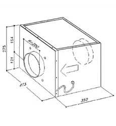
SEM 1 (fig.1)
Warning! The peripheral exhausting group (remote fitted extract
ion motor) is built in class II (symbol on the rating
plate), therefore it must not be earthed.
The appliance is designed to exhaust fumes and odours very silently and in the best way. It must be installed in the house
and connected to the cooker-hood, which is in the kitchen (fig. 2) or to the SCET control unit 1.
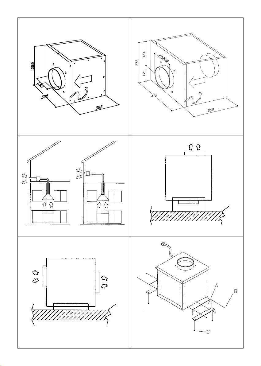
Types of installation: to make the installation easy, the appliance can be fixed on the wall, on the ceiling or on the floor
in a horizon
tal position (fig. 3 ) or vertically (fig. 4) to the fixing level.
Note: in the vertical fixing, the brackets supplied can be used only on the longest side (fig. 6).
Installation of the appliance: after deciding the position and the type of installation, insert the anti-vibration rubber caps
in the holes of the brackets supplied (fig. 5C).
The rubber caps must be put on the sides which are in contact with the wall.
Put the brackets (fig. 5A) on the remote fitted extract
ion motor by matching its holes with those of the brackets. Fix with
the screws supplied (fig. 5B).
Put the group on the point previously chosen for the installation and mark the points on the wall where the holes must
be drilled.
Insert the dowels supplied in the holes (fig. 6A). Put the remote fitted extraction motor on the wall by matching the holes
of the brackets with the plastic dowels. Screw with the screws supplied (fig. 6B).
Connection of the pipes: the appliance is endowed with an entra
nce and an outlet to connect the pipes. Before connecting
the exhaust pipes, check the direction of the air showed on the external label (fig. 7). Connect the pipes and fix them with
appropriate metal clamps (exhaust pipes and metal clamps have to be supplied by the installer). The pipe (fig. 7A) must
be connected with the cooker-hood placed in the kitchen, and the pipe (fig. 7B) must be directed outside the building.
Electrical connection of the hood: the appliance is equipped with a 7m elec
trical cable with a six- pin connection at one
end. Insert it into the hood’s connection (External Motor version) or into the SCET-1 central unit (see fig. 8 for the end
result).
SEM 2 (fig.9)
Warning! The remote fitted exhausting group (external motor) is built in class I plate, therefore it needs the earth
connection.
The appliance was designed to exhaust odours and vapours in the best way. The appliance is to be installed on the outside
wall of the house and connetted to the cooker-hood
which is in the kitchen (fig. 10) or to the SCET control unit 1.
Installation: the mounting of the appliance is to be made by qualified technicians. Using the appropriate drilling jig (fig.
11) drill all the holes marked on it into the external wall, by paying attention not to damage water pipes or power lines.
The holes on the wall are to be drilled with a 8 mm. bit. Insert, step by step, the following parts in the holes drilled:
•the corresponding plastic dowels supplied (fig. 11A)
•the two telescopic pipes in the hole of 16
0 mm.
•the plastic pipe of 40 mm. diameter.
Before leaning the appliance against the wall, insert the supply cord in the plastic pipe. Fix the appliance without the
stainless steel external body, which was previously removed from the motor block, by matching the holes of the motor
block with the holes on the wall. Tighten with the screws supplied (fig.11B).
Connection of the pipes: the appliance is endowed with an air entrance to be connected with the telescopic pipes and an
air outlet.
After fix
ing the appliance on the external wall, connect the two telescopic pipes, which are placed inside the wall, with the
cooker-hood through the flexible pipes (fig. 12).
The fixing between the pipes have to be made with appropriate metal clamps (pipes and clamps are supplied by the
installer).
Electrical connection of the hood: the appliance is equipped with a 7m electrical cable. Make the cable pass through the
plastic hose in the wall (see fig. 12E), connect it to the appliance in the kitchen and
then connect the ground wire to the
screw near the connection by means of nut and washer (see fig. 14). You can otherwise make the electrical connection
to the SCET-1 central unit.
In or der to avoid water infiltrations, pl eas eapp ly silicon e on theproduc t per imeter, clos e to the wall.
Installation of the stainless steel external body: put the stainless steel body again, by matching the air exhausting grid
with the air outlet of the motor block (fig. 13).
90004200072 - GM 07/10
23
19
SEM 1
1 2
3
4 5
6 7
8
3
2
OK
OK
OK
OK
OK
OK
OK
OK
OK
OK
OK
OK
OK
OK
OK OK
OK
OK
OK
OK
OK
OK
OK
SEM 1 (dis.1)
Attenzione! Il gruppo di aspirazione periferico (centralina) SEM 1 è in classe II (simbolo sulla targhetta dati tecnici
), pertanto non necessita di collegamento a terra.
L’appa recchio è stato progettato per aspirare i vapori e gli odori in modo otti male con estrema silenziosità.
L’apparecchio dovrà essere istallato all’interno dell’abitazione collegandolo alla cappa che si trova in cucina (dis.2) o alla
unità di comando SCET - 1.
Modalità di fissaggio: per facilitare le operazioni di in
stallazione, l’apparecchio può essere fissato a parete, a soffitto o
sul pavimento in posizione orizzontale (dis.3) o verticale (dis.4) rispetto al piano di fissaggio.
NOTA: Nel caso del fissaggio verticale, si possono utilizzare le staffe in dotazione solo dalla parte più lunga (fig. 6).
Fissaggio dell’apparecchio: una volta stabilito la posizione e il modo di fissaggio, bisogna introdurre i gommini anti-
vibrazioni nelle staffe in dotazione (dis.5C).
I gommini
vanno messi nei lati che andranno a contatto con il muro.
Appoggiare le staffe (dis.5A) sulla centralina facendo coincidere i fori di quest’ultima con quelli delle staffe e fissare con
le viti in dotazione (dis.5B)
Appoggiare il tutto nel punto di fissaggio deciso in precedenza segnando, sulla parete, i punti dove bisognerà effettuare i fori.
Nei fori eseguiti inserire i tasselli in dotazione (dis.6A).
Appoggiare la centralina sulla parete facendo coincidere i fori de
lle staffe con i tasselli in plastica e avvitare il tutto con le
viti in dotazione (dis.6B).
Collegamento dei tubi: l’apparecchio è predisposto con un’entrata e un’uscita per il collegamento dei tubi (verificare la
direzione dell’aria tramite l’etichetta esterna prima del montaggio dei tubi di evacuazione dis.7), collegare i tubi e fissarli
con idonee fascette metalliche (tubi e fascette sono a cura dell’installatore). Il tubo (dis.7A) va collegato alla cappa posta
nella cucina, il tubo (dis.7B) va indirizzato ve
rso l’esterno dell’edificio.
Collegamento elettrico alla cappa: l’apparecchio è dotato di un cavo di collegamento lungo 7 metri. Il cavo, alla sua estremità,
ha una connessione a sei poli che deve essere inserita in quella fissata sulla cappa (dis.8) o alla unità di comando SCET - 1.
SEM 2
(dis.9)
Attenzione! Il gruppo di aspirazione periferico (centralina) SEM 2 è in classe I e pertanto necessita di collegamento
a terra.
L’apparecc
hio è stato progettato per aspirare i vapori e gli odori in modo ottimale.
L’apparecchio dovrà essere istallato all’esterno dell’abitazione collegandolo alla cappa che si trova in cucina (dis.10) o alla
unità di comando SCET - 1.
Modalità di fissaggio: il montaggio dell’apparecchio deve essere effettuato da personale qualificato. Usando l’apposita
maschera di foratura (dis.11) praticare sulla parete esterna tutti i fori indicati nella stessa facendo attenzione a non
danneggiare tubature dell’a
cqua o linee elettriche.
I fori alla parete dovranno essere effettuati con una punta da da 8 mm. Nei fori praticati dovranno essere progressivamente:
•Inseriti i relativi tasselli in plastica in dotazione (dis.11A).
•Inseriti i due tubi telescopici nel foro da 160 mm.
•Inserire il tubo in plastica da 40 mm.
Prima di appoggiare l’apparecchio sul muro bisogna inserire la connessione elettrica nel tubo in plastica. Fissare l
’apparecchio
senza carter estetico in acciaio, precedentemente tolto dal blocco motore, facendo coincidere i fori del blocco motore
stesso con i fori sul muro e serrando con le viti in dotazione (dis.11B).
Collegamento dei tubi: l’apparecchio è predisposto con un entrata dell’aria per il collegamento dei tubi telescopici, e un
uscita.
Dopo che l’apparecchio è stato fissato alla parete esterna, i due tubi telescopici posti all’interno della parete devono essere
colle
gati con la cappa tramite i tubi flessibili (dis.12).
Il fissaggio tra i tubi deve essere effettuato con idonee fascette metalliche (tubi e fascette sono a cura dell’installatore).
Collegamento elettrico alla cappa: l’apparecchio è dotato di un cavo di collegamento lungo 7 metri. Dopo aver fatto
passare il cavo attraverso il tubo in plastica posto nel muro, inserire la connessione a sei poli sulla cappa e collegare il
filo messa a terra sulla vite adiacente alla connessione tramite dado e rondella (dis.14), in
alternativa il collegamento
elettrico va fatto alla unità di comando SCET - 1.
Al fine di evitare possibili infiltrazioni d'acqua disporre accuratamente del silicone in corrispondenza del perimetro del
prodotto, in prossimità del muro.
Montaggio carter esterno: rimontare il carter estetico facendo coincidere la griglia con l’uscita aria del blocco motore (dis.13).
47
SEM 1 (fig.1)
Warning! The peripheral exhausting group (remote fitted extract
ion motor) is built in class II (symbol on the rating
plate), therefore it must not be earthed.
The appliance is designed to exhaust fumes and odours very silently and in the best way. It must be installed in the house
and connected to the cooker-hood, which is in the kitchen (fig. 2) or to the SCET control unit 1.
Types of installation: to make the installation easy, the appliance can be fixed on the wall, on the ceiling or on the floor
in a horizon
tal position (fig. 3 ) or vertically (fig. 4) to the fixing level.
Note: in the vertical fixing, the brackets supplied can be used only on the longest side (fig. 6).
Installation of the appliance: after deciding the position and the type of installation, insert the anti-vibration rubber caps
in the holes of the brackets supplied (fig. 5C).
The rubber caps must be put on the sides which are in contact with the wall.
Put the brackets (fig. 5A) on the remote fitted extract
ion motor by matching its holes with those of the brackets. Fix with
the screws supplied (fig. 5B).
Put the group on the point previously chosen for the installation and mark the points on the wall where the holes must
be drilled.
Insert the dowels supplied in the holes (fig. 6A). Put the remote fitted extraction motor on the wall by matching the holes
of the brackets with the plastic dowels. Screw with the screws supplied (fig. 6B).
Connection of the pipes: the appliance is endowed with an entra
nce and an outlet to connect the pipes. Before connecting
the exhaust pipes, check the direction of the air showed on the external label (fig. 7). Connect the pipes and fix them with
appropriate metal clamps (exhaust pipes and metal clamps have to be supplied by the installer). The pipe (fig. 7A) must
be connected with the cooker-hood placed in the kitchen, and the pipe (fig. 7B) must be directed outside the building.
Electrical connection of the hood: the appliance is equipped with a 7m elec
trical cable with a six- pin connection at one
end. Insert it into the hood’s connection (External Motor version) or into the SCET-1 central unit (see fig. 8 for the end
result).
SEM 2
(fig.9)
Warning! The remote fitted exhausting group (external motor) is built in class I plate, therefore it needs the earth
connection.
The appliance was designed to exhaust odours and vapours in the best way. The appliance is to be installed on the outside
wall of the house and connetted to the cooker-hood
which is in the kitchen (fig. 10) or to the SCET control unit 1.
Installation: the mounting of the appliance is to be made by qualified technicians. Using the appropriate drilling jig (fig.
11) drill all the holes marked on it into the external wall, by paying attention not to damage water pipes or power lines.
The holes on the wall are to be drilled with a 8 mm. bit. Insert, step by step, the following parts in the holes drilled:
•the corresponding plastic dowels supplied (fig. 11A)
•the two telescopic pipes in the hole of 16
0 mm.
•the plastic pipe of 40 mm. diameter.
Before leaning the appliance against the wall, insert the supply cord in the plastic pipe. Fix the appliance without the
stainless steel external body, which was previously removed from the motor block, by matching the holes of the motor
block with the holes on the wall. Tighten with the screws supplied (fig.11B).
Connection of the pipes: the appliance is endowed with an air entrance to be connected with the telescopic pipes and an
air outlet.
After fix
ing the appliance on the external wall, connect the two telescopic pipes, which are placed inside the wall, with the
cooker-hood through the flexible pipes (fig. 12).
The fixing between the pipes have to be made with appropriate metal clamps (pipes and clamps are supplied by the
installer).
Electrical connection of the hood: the appliance is equipped with a 7m electrical cable. Make the cable pass through the
plastic hose in the wall (see fig. 12E), connect it to the appliance in the kitchen and
then connect the ground wire to the
screw near the connection by means of nut and washer (see fig. 14). You can otherwise make the electrical connection
to the SCET-1 central unit.
In order to avoid water infiltrations, pl eas eapply silicon e on theproduc t per imeter, close to the wall.
Installation of the stainless steel external body: put the stainless steel body again, by matching the air exhausting grid
with the air outlet of the motor block (fig. 13).
90004200072 - GM 07/10
23
19
SEM 1
1 2
3
4 5
6 7
8
2
OK
OK
OK
OK
OK
OK
OK
OK
OK
OK
OK
OK
OK
OK
OK OK
OK
OK
OK
OK
OK
OK
OK
SEM 1 (dis.1)
Attenzione! Il gruppo di aspirazione periferico (centralina) SEM 1 è in classe II (simbolo sulla targhetta dati tecnici
), pertanto non necessita di collegamento a terra.
L’appa recchio è stato progettato per aspirare i vapori e gli odori in modo otti male con estrema silenziosità.
L’apparecchio dovrà essere istallato all’interno dell’abitazione collegandolo alla cappa che si trova in cucina (dis.2) o alla
unità di comando SCET - 1.
Modalità di fissaggio: per facilitare le operazioni di in
stallazione, l’apparecchio può essere fissato a parete, a soffitto o
sul pavimento in posizione orizzontale (dis.3) o verticale (dis.4) rispetto al piano di fissaggio.
NOTA: Nel caso del fissaggio verticale, si possono utilizzare le staffe in dotazione solo dalla parte più lunga (fig. 6).
Fissaggio dell’apparecchio: una volta stabilito la posizione e il modo di fissaggio, bisogna introdurre i gommini anti-
vibrazioni nelle staffe in dotazione (dis.5C).
I gommini
vanno messi nei lati che andranno a contatto con il muro.
Appoggiare le staffe (dis.5A) sulla centralina facendo coincidere i fori di quest’ultima con quelli delle staffe e fissare con
le viti in dotazione (dis.5B)
Appoggiare il tutto nel punto di fissaggio deciso in precedenza segnando, sulla parete, i punti dove bisognerà effettuare i fori.
Nei fori eseguiti inserire i tasselli in dotazione (dis.6A).
Appoggiare la centralina sulla parete facendo coincidere i fori de
lle staffe con i tasselli in plastica e avvitare il tutto con le
viti in dotazione (dis.6B).
Collegamento dei tubi: l’apparecchio è predisposto con un’entrata e un’uscita per il collegamento dei tubi (verificare la
direzione dell’aria tramite l’etichetta esterna prima del montaggio dei tubi di evacuazione dis.7), collegare i tubi e fissarli
con idonee fascette metalliche (tubi e fascette sono a cura dell’installatore). Il tubo (dis.7A) va collegato alla cappa posta
nella cucina, il tubo (dis.7B) va indirizzato ve
rso l’esterno dell’edificio.
Collegamento elettrico alla cappa: l’apparecchio è dotato di un cavo di collegamento lungo 7 metri. Il cavo, alla sua estremità,
ha una connessione a sei poli che deve essere inserita in quella fissata sulla cappa (dis.8) o alla unità di comando SCET - 1.
SEM 2 (dis.9)
Attenzione! Il gruppo di aspirazione periferico (centralina) SEM 2 è in classe I e pertanto necessita di collegamento
a terra.
L’apparecc
hio è stato progettato per aspirare i vapori e gli odori in modo ottimale.
L’apparecchio dovrà essere istallato all’esterno dell’abitazione collegandolo alla cappa che si trova in cucina (dis.10) o alla
unità di comando SCET - 1.
Modalità di fissaggio: il montaggio dell’apparecchio deve essere effettuato da personale qualificato. Usando l’apposita
maschera di foratura (dis.11) praticare sulla parete esterna tutti i fori indicati nella stessa facendo attenzione a non
danneggiare tubature dell’a
cqua o linee elettriche.
I fori alla parete dovranno essere effettuati con una punta da da 8 mm. Nei fori praticati dovranno essere progressivamente:
•Inseriti i relativi tasselli in plastica in dotazione (dis.11A).
•Inseriti i due tubi telescopici nel foro da 160 mm.
•Inserire il tubo in plastica da 40 mm.
Prima di appoggiare l’apparecchio sul muro bisogna inserire la connessione elettrica nel tubo in plastica. Fissare l
’apparecchio
senza carter estetico in acciaio, precedentemente tolto dal blocco motore, facendo coincidere i fori del blocco motore
stesso con i fori sul muro e serrando con le viti in dotazione (dis.11B).
Collegamento dei tubi: l’apparecchio è predisposto con un entrata dell’aria per il collegamento dei tubi telescopici, e un
uscita.
Dopo che l’apparecchio è stato fissato alla parete esterna, i due tubi telescopici posti all’interno della parete devono essere
colle
gati con la cappa tramite i tubi flessibili (dis.12).
Il fissaggio tra i tubi deve essere effettuato con idonee fascette metalliche (tubi e fascette sono a cura dell’installatore).
Collegamento elettrico alla cappa: l’apparecchio è dotato di un cavo di collegamento lungo 7 metri. Dopo aver fatto
passare il cavo attraverso il tubo in plastica posto nel muro, inserire la connessione a sei poli sulla cappa e collegare il
filo messa a terra sulla vite adiacente alla connessione tramite dado e rondella (dis.14), in
alternativa il collegamento
elettrico va fatto alla unità di comando SCET - 1.
Al fine di evitare possibili infiltrazioni d'acqua disporre accuratamente del silicone in corrispondenza del perimetro del
prodotto, in prossimità del muro.
Montaggio carter esterno: rimontare il carter estetico facendo coincidere la griglia con l’uscita aria del blocco motore (dis.13).
47
SEM 1 (fig.1)
Warning! The peripheral exhausting group (remote fitted extract
ion motor) is built in class II (symbol on the rating
plate), therefore it must not be earthed.
The appliance is designed to exhaust fumes and odours very silently and in the best way. It must be installed in the house
and connected to the cooker-hood, which is in the kitchen (fig. 2) or to the SCET control unit 1.
Types of installation: to make the installation easy, the appliance can be fixed on the wall, on the ceiling or on the floor
in a horizon
tal position (fig. 3 ) or vertically (fig. 4) to the fixing level.
Note: in the vertical fixing, the brackets supplied can be used only on the longest side (fig. 6).
Installation of the appliance: after deciding the position and the type of installation, insert the anti-vibration rubber caps
in the holes of the brackets supplied (fig. 5C).
The rubber caps must be put on the sides which are in contact with the wall.
Put the brackets (fig. 5A) on the remote fitted extract
ion motor by matching its holes with those of the brackets. Fix with
the screws supplied (fig. 5B).
Put the group on the point previously chosen for the installation and mark the points on the wall where the holes must
be drilled.
Insert the dowels supplied in the holes (fig. 6A). Put the remote fitted extraction motor on the wall by matching the holes
of the brackets with the plastic dowels. Screw with the screws supplied (fig. 6B).
Connection of the pipes: the appliance is endowed with an entra
nce and an outlet to connect the pipes. Before connecting
the exhaust pipes, check the direction of the air showed on the external label (fig. 7). Connect the pipes and fix them with
appropriate metal clamps (exhaust pipes and metal clamps have to be supplied by the installer). The pipe (fig. 7A) must
be connected with the cooker-hood placed in the kitchen, and the pipe (fig. 7B) must be directed outside the building.
Electrical connection of the hood: the appliance is equipped with a 7m elec
trical cable with a six- pin connection at one
end. Insert it into the hood’s connection (External Motor version) or into the SCET-1 central unit (see fig. 8 for the end
result).
SEM 2
(fig.9)
Warning! The remote fitted exhausting group (external motor) is built in class I plate, therefore it needs the earth
connection.
The appliance was designed to exhaust odours and vapours in the best way. The appliance is to be installed on the outside
wall of the house and connetted to the cooker-hood
which is in the kitchen (fig. 10) or to the SCET control unit 1.
Installation: the mounting of the appliance is to be made by qualified technicians. Using the appropriate drilling jig (fig.
11) drill all the holes marked on it into the external wall, by paying attention not to damage water pipes or power lines.
The holes on the wall are to be drilled with a 8 mm. bit. Insert, step by step, the following parts in the holes drilled:
•the corresponding plastic dowels supplied (fig. 11A)
•the two telescopic pipes in the hole of 16
0 mm.
•the plastic pipe of 40 mm. diameter.
Before leaning the appliance against the wall, insert the supply cord in the plastic pipe. Fix the appliance without the
stainless steel external body, which was previously removed from the motor block, by matching the holes of the motor
block with the holes on the wall. Tighten with the screws supplied (fig.11B).
Connection of the pipes: the appliance is endowed with an air entrance to be connected with the telescopic pipes and an
air outlet.
After fix
ing the appliance on the external wall, connect the two telescopic pipes, which are placed inside the wall, with the
cooker-hood through the flexible pipes (fig. 12).
The fixing between the pipes have to be made with appropriate metal clamps (pipes and clamps are supplied by the
installer).
Electrical connection of the hood: the appliance is equipped with a 7m electrical cable. Make the cable pass through the
plastic hose in the wall (see fig. 12E), connect it to the appliance in the kitchen and
then connect the ground wire to the
screw near the connection by means of nut and washer (see fig. 14). You can otherwise make the electrical connection
to the SCET-1 central unit.
In order to avoid water infiltrations, pl eas eapply silicon e on theproduc t per imeter, close to the wall.
Installation of the stainless steel external body: put the stainless steel body again, by matching the air exhausting grid
with the air outlet of the motor block (fig. 13).
90004200072 - GM 07/10
23
19
SEM 1
1 2
3
4 5
6 7
8
2
OK
OK
OK
OK
OK
OK
OK
OK
OK
OK
OK
OK
OK
OK
OK OK
OK
OK
OK
OK
OK
OK
OK
SEM 1 (dis.1)
Attenzione! Il gruppo di aspirazione periferico (centralina) SEM 1 è in classe II (simbolo sulla targhetta dati tecnici
), pertanto non necessita di collegamento a terra.
L’appa recchio è stato prog ettato per aspirare i vapori e gli odori in modo otti male con estrema silenziosità.
L’apparecchio dovrà essere istallato all’interno dell’abitazione collegandolo alla cappa che si trova in cucina (dis.2) o alla
unità di comando SCET - 1.
Modalità di fissaggio: per facilitare le operazioni di in
stallazione, l’apparecchio può essere fissato a parete, a soffitto o
sul pavimento in posizione orizzontale (dis.3) o verticale (dis.4) rispetto al piano di fissaggio.
NOTA: Nel caso del fissaggio verticale, si possono utilizzare le staffe in dotazione solo dalla parte più lunga (fig. 6).
Fissaggio dell’apparecchio: una volta stabilito la posizione e il modo di fissaggio, bisogna introdurre i gommini anti-
vibrazioni nelle staffe in dotazione (dis.5C).
I gommini
vanno messi nei lati che andranno a contatto con il muro.
Appoggiare le staffe (dis.5A) sulla centralina facendo coincidere i fori di quest’ultima con quelli delle staffe e fissare con
le viti in dotazione (dis.5B)
Appoggiare il tutto nel punto di fissaggio deciso in precedenza segnando, sulla parete, i punti dove bisognerà effettuare i fori.
Nei fori eseguiti inserire i tasselli in dotazione (dis.6A).
Appoggiare la centralina sulla parete facendo coincidere i fori de
lle staffe con i tasselli in plastica e avvitare il tutto con le
viti in dotazione (dis.6B).
Collegamento dei tubi: l’apparecchio è predisposto con un’entrata e un’uscita per il collegamento dei tubi (verificare la
direzione dell’aria tramite l’etichetta esterna prima del montaggio dei tubi di evacuazione dis.7), collegare i tubi e fissarli
con idonee fascette metalliche (tubi e fascette sono a cura dell’installatore). Il tubo (dis.7A) va collegato alla cappa posta
nella cucina, il tubo (dis.7B) va indirizzato ve
rso l’esterno dell’edificio.
Collegamento elettrico alla cappa: l’apparecchio è dotato di un cavo di collegamento lungo 7 metri. Il cavo, alla sua estremità,
ha una connessione a sei poli che deve essere inserita in quella fissata sulla cappa (dis.8) o alla unità di comando SCET - 1.
SEM 2 (dis.9)
Attenzione! Il gruppo di aspirazione periferico (centralina) SEM 2 è in classe I e pertanto necessita di collegamento
a terra.
L’apparecc
hio è stato progettato per aspirare i vapori e gli odori in modo ottimale.
L’apparecchio dovrà essere istallato all’esterno dell’abitazione collegandolo alla cappa che si trova in cucina (dis.10) o alla
unità di comando SCET - 1.
Modalità di fissaggio: il montaggio dell’apparecchio deve essere effettuato da personale qualificato. Usando l’apposita
maschera di foratura (dis.11) praticare sulla parete esterna tutti i fori indicati nella stessa facendo attenzione a non
danneggiare tubature dell’a
cqua o linee elettriche.
I fori alla parete dovranno essere effettuati con una punta da da 8 mm. Nei fori praticati dovranno essere progressivamente:
•Inseriti i relativi tasselli in plastica in dotazione (dis.11A).
•Inseriti i due tubi telescopici nel foro da 160 mm.
•Inserire il tubo in plastica da 40 mm.
Prima di appoggiare l’apparecchio sul muro bisogna inserire la connessione elettrica nel tubo in plastica. Fissare l
’apparecchio
senza carter estetico in acciaio, precedentemente tolto dal blocco motore, facendo coincidere i fori del blocco motore
stesso con i fori sul muro e serrando con le viti in dotazione (dis.11B).
Collegamento dei tubi: l’apparecchio è predisposto con un entrata dell’aria per il collegamento dei tubi telescopici, e un
uscita.
Dopo che l’apparecchio è stato fissato alla parete esterna, i due tubi telescopici posti all’interno della parete devono essere
colle
gati con la cappa tramite i tubi flessibili (dis.12).
Il fissaggio tra i tubi deve essere effettuato con idonee fascette metalliche (tubi e fascette sono a cura dell’installatore).
Collegamento elettrico alla cappa: l’apparecchio è dotato di un cavo di collegamento lungo 7 metri. Dopo aver fatto
passare il cavo attraverso il tubo in plastica posto nel muro, inserire la connessione a sei poli sulla cappa e collegare il
filo messa a terra sulla vite adiacente alla connessione tramite dado e rondella (dis.14), in
alternativa il collegamento
elettrico va fatto alla unità di comando SCET - 1.
Al fine di evitare possibili infiltrazioni d'acqua disporre accuratamente del silicone in corrispondenza del perimetro del
prodotto, in prossimità del muro.
Montaggio carter esterno: rimontare il carter estetico facendo coincidere la griglia con l’uscita aria del blocco motore (dis.13).
47
SEM 1 (fig.1)
Warning! The peripheral exhausting group (remote fitted extract
ion motor) is built in class II (symbol on the rating
plate), therefore it must not be earthed.
The appliance is designed to exhaust fumes and odours very silently and in the best way. It must be installed in the house
and connected to the cooker-hood, which is in the kitchen (fig. 2) or to the SCET control unit 1.
Types of installation: to make the installation easy, the appliance can be fixed on the wall, on the ceiling or on the floor
in a horizon
tal position (fig. 3 ) or vertically (fig. 4) to the fixing level.
Note: in the vertical fixing, the brackets supplied can be used only on the longest side (fig. 6).
Installation of the appliance: after deciding the position and the type of installation, insert the anti-vibration rubber caps
in the holes of the brackets supplied (fig. 5C).
The rubber caps must be put on the sides which are in contact with the wall.
Put the brackets (fig. 5A) on the remote fitted extract
ion motor by matching its holes with those of the brackets. Fix with
the screws supplied (fig. 5B).
Put the group on the point previously chosen for the installation and mark the points on the wall where the holes must
be drilled.
Insert the dowels supplied in the holes (fig. 6A). Put the remote fitted extraction motor on the wall by matching the holes
of the brackets with the plastic dowels. Screw with the screws supplied (fig. 6B).
Connection of the pipes: the appliance is endowed with an entra
nce and an outlet to connect the pipes. Before connecting
the exhaust pipes, check the direction of the air showed on the external label (fig. 7). Connect the pipes and fix them with
appropriate metal clamps (exhaust pipes and metal clamps have to be supplied by the installer). The pipe (fig. 7A) must
be connected with the cooker-hood placed in the kitchen, and the pipe (fig. 7B) must be directed outside the building.
Electrical connection of the hood: the appliance is equipped with a 7m elec
trical cable with a six- pin connection at one
end. Insert it into the hood’s connection (External Motor version) or into the SCET-1 central unit (see fig. 8 for the end
result).
SEM 2 (fig.9)
Warning! The remote fitted exhausting group (external motor) is built in class I plate, therefore it needs the earth
connection.
The appliance was designed to exhaust odours and vapours in the best way. The appliance is to be installed on the outside
wall of the house and connetted to the cooker-hood
which is in the kitchen (fig. 10) or to the SCET control unit 1.
Installation: the mounting of the appliance is to be made by qualified technicians. Using the appropriate drilling jig (fig.
11) drill all the holes marked on it into the external wall, by paying attention not to damage water pipes or power lines.
The holes on the wall are to be drilled with a 8 mm. bit. Insert, step by step, the following parts in the holes drilled:
•the corresponding plastic dowels supplied (fig. 11A)
•the two telescopic pipes in the hole of 16
0 mm.
•the plastic pipe of 40 mm. diameter.
Before leaning the appliance against the wall, insert the supply cord in the plastic pipe. Fix the appliance without the
stainless steel external body, which was previously removed from the motor block, by matching the holes of the motor
block with the holes on the wall. Tighten with the screws supplied (fig.11B).
Connection of the pipes: the appliance is endowed with an air entrance to be connected with the telescopic pipes and an
air outlet.
After fix
ing the appliance on the external wall, connect the two telescopic pipes, which are placed inside the wall, with the
cooker-hood through the flexible pipes (fig. 12).
The fixing between the pipes have to be made with appropriate metal clamps (pipes and clamps are supplied by the
installer).
Electrical connection of the hood: the appliance is equipped with a 7m electrical cable. Make the cable pass through the
plastic hose in the wall (see fig. 12E), connect it to the appliance in the kitchen and
then connect the ground wire to the
screw near the connection by means of nut and washer (see fig. 14). You can otherwise make the electrical connection
to the SCET-1 central unit.
In or der to avoid water infiltrations, pleas eapply silicon e on theproduc t per imeter, close to the wall.
Installation of the stainless steel external body: put the stainless steel body again, by matching the air exhausting grid
with the air outlet of the motor block (fig. 13).
90004200072 - GM 07/10
23
19
SEM 1
1 2
3
4 5
6 7
8
SEM1
Loading ...
Loading ...
Loading ...