Loading ...
Loading ...
Loading ...
4
© 2021 United States Stove Company
SPECIFICATIONS
CAUTION:
DISCONNECT THE POWER CORD BEFORE
SERVICING THIS HEATER
For the following assemblies, we suggest locating the
unit near it’s desired location. Depending on installation,
you may want to connect the exhaust venting before
installing the facade parts.
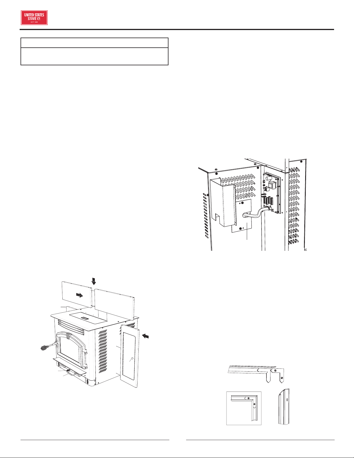
ASSEMBLY FACADE (SURROUND)
Remove contents from packaging and make sure you
have all components:
(2) Top Facade (a)
(1) Left Side Facade (b)
(1) Right Side Facade (c)
(4 pieces)Facade Trim Kit (d)
(1) Feed Door Spring Handle (e)
(1) Damper Spring Handle (f)
(1) Ash Pan “U” shaped Handle (g)
(1) Access Door Knob (h)
(1) PCB Cover (i)
(1) Panel Cover (j)
(1) Auger (in ash pan)
(1) Power Cord
(1) Burnpot Poker (k)
(a)
(a)
(c)
(h)
(f)
(g)
(b)
(e)
MOUNTING HARDWARE
Start by mounting either the left or right side facade
pieces to the unit using four(4) of the supplied #10 x 1/2
screws. Then put the two(2) top facade pieces together
with two(2) of the #10 x 1/2 screws provided. Attach the
top facade assembly to the unit with eight(8) of the same
screws.
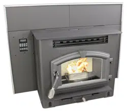
CONTROL BOARD (PCB) RELOCATION
Remove the left side front panel from the unit. While
holding the PCB with one hand, remove the two(2) hex
head screws holding the board in place. It is not necessary
to unplug the PCB cable. Route the board and cable
through the opening and mount it to the Left Facade using
two of the #10 x 1/2 phillips head screws provided. Then
attach the PCB cover to the back of the facade covering
the board. Next, use the two hex head screws removed
earlier and mount the cover panel over the opening where
the PCB was located. See illustration to the left.
(i)
(j)
FACADE TRIM
Remove trim from shipping tube. There should be
one(1) left side, one(1) right side, two(2) top pieces, and
mounting hardware. Using one blank corner key and one
corner key with set screws, assemble the left trim and
one of the top pieces together. As illustrated, place the
blank key behind the key with the set screws. Adjust
corners and tighten set screws. Repeat this for the right
sideBefore removing tape, place trim assembly against
facade to get an idea of how it is to be mounted. Remove
the strip from the adhesive and carefully secure the trim
in place by firmly pressing it to the facade.
(d)
Loading ...
Loading ...
Loading ...