
Loading ...
Loading ...
Loading ...
W415-2349 / A / 10.31.19
EN
10
direct venting - model GDS60-1
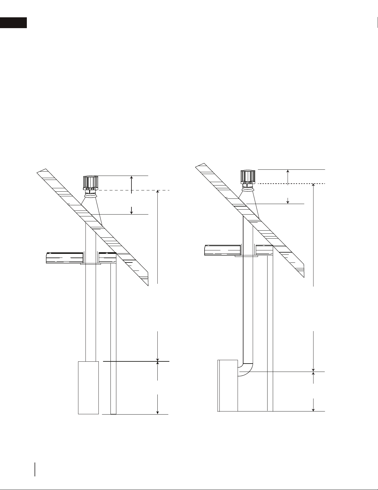
2.1 typical vent installations
TOP VENT
REAR VENT
24"
(61cm)
16" (40.6cm)
min.
40 ft. (12m)
max.
34" (864mm)
min.
40 ft. (12m)
max.
34" (864mm) min.
Horizontal runs may have a 0” rise per foot or 0mm rise per meter however for optimum performance it is recommended
that all horizontal runs have a minimum 1/4” rise per foot or 21mm rise per meter using fl exible venting. For safe and proper
operation of the appliance, follow the venting instructions exactly.
A terminal shall not terminate directly above a sidewalk or paved driveway which is located between two single family dwellings
and serves both dwellings. Local codes or regulations may require different clearances.
Do not allow the inside liner to bunch up on horizontal or vertical runs and elbows. Keep it pulled tight. A 1¼” (31.8mm) air gap
all around between the inner liner and outer liner is required for safe operation.
If approved for use with a power vent kit, state: “This appliance is certifi ed for use with a
power vent kit. Contact your local authorized dealer for more information.”
If not, cover with a white box.
Use a fi restop when penetrating interior walls, fl oor or ceiling.
A terminal shall not terminate directly above a sidewalk or paved driveway which is located between
two single family dwellings and serves both dwellings. Local codes or regulations may require different
clearances.
Use only Wolf Steel, Simpson Dura-Vent, Selkirk Direct Temp or American Metal Amerivent venting components.
Minimum and maximum vent lengths, for both horizontal and vertical installations, and air terminal locations for
either systems are set out in this manual and must be adhered to.
30 1/2"
(77.5cm)
16" (40.6cm)
min.
Loading ...
Loading ...
Loading ...