Loading ...
Loading ...
Loading ...
E,.ViBLV
UNPACK CARTON & INSTALL HANDLE
_ BE CAREFUL OF EXPOSED STAPLES
WHEN HANDLING OR DISPOSING OF
CAR'i'ONING MATERIAL°
CAUTION: Wt4EN UNPACKING AND ASSEMBLING
TILLER, BE CAREFUL NOT TO STRETCH
OR KINK CABLES
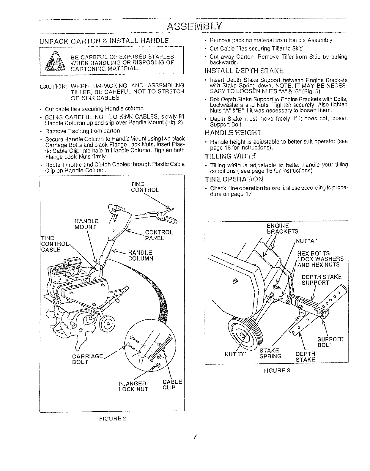
• Cut cable ties securing Handle column
• BEING CAREFUL NOT TO KINK CABLES, slowly lift
Handle Column up and slip over Handle Mounl (Fig, 2)
• Remove Packing from carton
• Secure HandleColumn to Handle Mounlusinglwoblack
Carriage Bolts and black Flange Lock Nuts, Insert Plas-
tic Cable Clip into hole in Handle Column Tighten bolh
Flange Lock Nuls limlly.
• Roule Throttle and Clulch Cables through Plastic Cable
Clip on Handle Column.
TINE
CONTROL,
HANDLE
MOUNT
CONTROL
TINE PANEL
COLUMN
CARRIAGE
BOLl"
FLANGED CABLE
LOCK NUT CLiP
• Remove packing matedal from Handle Assembly
o Cut Cable Ties securing Tiller to Skid
• Cut away Carlon Remove Tiller lrom Skid by pulling
backwards
INSTALL DEPTH S'I-AKE
• Insed Depth Slake Support beh*zeenEngine Brackets
with Stake Spring down, NOTE: IT MAY BE NECES_
SARY TO LOOSEN NUTS "A" & "B" (Fig. 3)
• Boll DepthStake Support Io Engine Brackets with Bolls,
Lockwashers and Nuls Tighten securely. Also lighten
Nuts "A" &"B" if it was necessary fo loosen Ihem_
• Deplh Stake must move freely, If it does not, loosen
Support Bolt
HANDLE HEIGHT
• Handle height is adjustable to better suit operator (see
page 16 for instructions),
TILLING WIDTH
• Tilling width is adjuslable to beller handle your tilling
conditions ( see page 16 for instructions)
TINE OPERATION
• Check Tine operation before first useaccording to proce-
dure on page 17
ENGINE
BRACKETS
: BOLTS
STAKE
NUT"B" SPRING
FIGURE 3
DEPTH
STAKE
SUPPORT
BOLT
FIGURE 2
7
Loading ...
Loading ...
Loading ...