• / t_J f ___
_/A/,_
OWNER'S
MANUAL
MODEL NO.
917.298231
Caution:
Read and follow
all Safety Rules
and Instructions
Before Operating
This Equipment
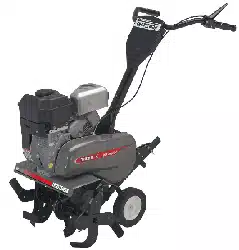
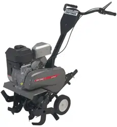
Place Photo Here
3,0 HORSEPOWER
17 RNCH Tt E WIDTH
FRONT TNNE TALLER
Assembly
Operation
Maintenance
Service and Adjustment
Repair Parts
Sears, Roebuck and Co,, Chicago, IL 60684 UoS.A,
SAFETY RULES
_2-'_} Safe Operation Practices for Walk-Behind Powered Rotaiy Tillel s _._,_l_._i},'_
]'RAINING
Read the operating and service instruction manual
carefully Be thoroughly familiar wilh the controls end
the proper use of the equipment Know how to slop the
unit and disengage the controls quickly
Never allow children to operate Ihe equipment Never
allow adults to operale the equipment without proper
instruction.
Keep the area of operation clear of all persons, particu-
larly small children, and pets
PREPARATION
• Thoroughly inspect the area where the equipment_isto
be used and remove all foreign objects.
Disengage all clutches and shill into neutral before
starting the engine (motor)
Do not operate the equipment without wearing ade-
quate outer garmenls. Wear footwear that will improve
footing on slippery s_daces.
• Handle fuel with:care; it is highly flammable
• Lisa an ap.prbved fue .con alner
Never add fuel to a running engine or hot engine.
Fill fuel tank outdoors with extreme care Never fill
fuel tank indoors
Replace gasoline cap securely and clean up spilled
fuel before restading.
• Useextension cords and receptacles as specified bythe
manufacturer for all units with electric drive motors or
electric starting motors.
• Never attempt to make any adjustments while the engine
(motor) is running (except where specifically recom-
mended by manutacturer).
OPERATION
• Do not put hands or feet near or under rotating parts
• Exercise extreme caution when operating on or crossing
gravel drives, walks, or roads Stay alert for hidden
hazards or traffic. Do not carry passengers.
• After striking a foreign object, stop the engine (motor),
remove the wire from the spark plug, thoroughly inspect
the tiller for any damage, and repair the damage before
restariing and operating the tiller.
• Exercise caution to avoid slipping or failing
• !l the unit should stad to vibrate abnomlally, stop the
engine (motor) and check immediately for the cause Vi-
bration is generally a warning of trouble.
• Slop the engine (motor) when leaving the operating
position, before unclogging the tines, and when making
any repair, adjuslments, and inspections
• "Fakeall possible precautions when leaving the machine
unattended Disengage Ihe power take-off, lower the
attachment, shift into neutral, stop the engine, and
remove the key
• Before cleaning, repairing, or inspecting, shut off [he
engine and make certain all moving parts have stoppe&
Disconnect the spark plug wire, and keep thewire away
from the plug lo prevent accidental starting. Disconnec!
the cord on electric molors.
• Do not run the engine indoors; exhaust fumes are dan-
gerous.
• Never operate the tiller wilhout proper guards, plates, or
other safety protective devices in place
• Keep children and pets away
• Donot overload the machine capacity by attempting totill
too deep at too fast a rate
• Never allow bystanders near the unit
• Useonly attachments and accessories approved by the
manufacturer ofthetiller (such aswheelweighls, co_ "-
weights, cabs, and the like).
• Never operate the tiller without good visibilily or light
, Be careful when tilling in hard ground. Tile tines may
catch in the ground and propel the tiller forward. If this
occurs, let go of the hand!ebars and do not restrain the
machine.
MAINTENANCE ANDSTORAGE
• Keep machine, attachments, and accessories in safe
working condition_
• Check shear bolts, engine mounting bolts, and other
bolts at frequenl intervals lor proper tightness to be sure
the equipment is in safe working condition.
• Never store the machine with fuel in the fuel lank inside
abuilding where ignition sources are present, such ashol
waler and space heaters, clothes dryers, and the like
Allow the engine to cool before storing in any enclosure
• Always refer to the operalor's guide instructions for
important details ifthe tiller istobe stored for an extended
period
-IMPORTANT
Warnings, Cautions, and Notes are a means of attracting altention to important or critical information in this manual
LOOK FOR THIS SYMBOL TO POINT
OUT IMPOR'rANT SAFETY PRE-
CAUTIONS. IT MEANS -- ATTENTION!
BECOME ALERT! YOUR SAFETY IS
INVOLVED.
CAUTION: USED TO ALERT' YOU THAT ]'HERE IS
A POSSIBILITY OF DAMAGING ':
EQUIPMENT
NOTE: Gives essential information that will aid you to
better understand, incorporate, or execute a particular
set of instructions
2
CONGRAI_ULATIONS on your purchase of a Sears
Craftsman "Filler. il has been designed, engineered and
manufactured to give you the best possible dependabilily
and pedormance
Should you experience any problems you cannot easily
remedy, please contact your nearest Sears Service Cen-
ter/Depadment We have compelenl, well trained techni-
cians and the proper tools to service or repair this unit
Please read and retain this manual. The instructions will
enable you to assemble and maintain your Tiller prop-
erly Always observe the "SAFETY" RULES"
MODEL
NUMBER 917 298231
SERIAL
NUMBER
DATE OF
PLtRCHASE
THE MODEL AND SERIAL NUMBEFiS WILL BE
FOUND ON THE MODEL PLATE ATTACHED TO
THE RIGHT HAND ENGINE BRACKET_
YOU SHOULD RECORD BOTH SERIAL NUMBER
AND DATE OF PURCHASE AND KEEP tN A SAFE
PLACE FOR FUTURE REFERENCE.
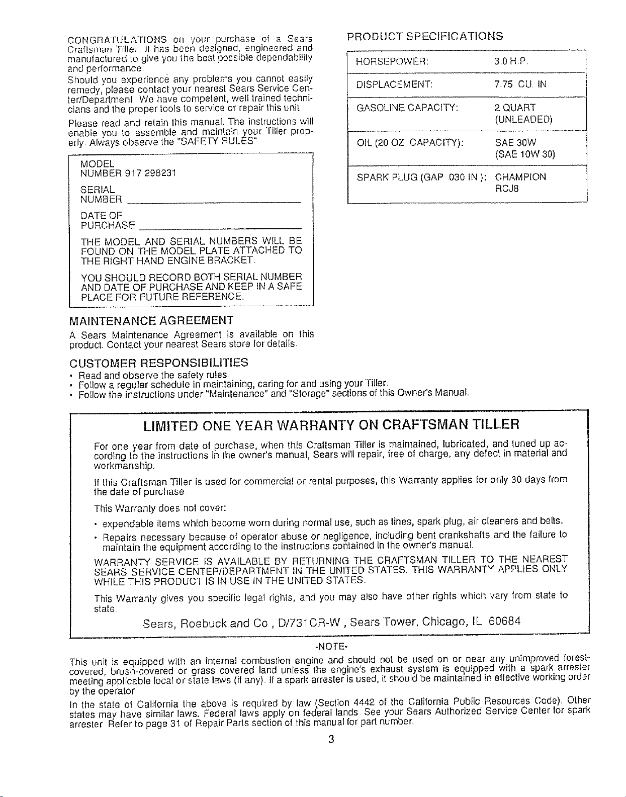
PRODUCT SPECIFICATIONS
HORSEPOWER: 30 HP
DISPLACEMENT: 7 75 CU IN
GASOLINE CAPACITY: 2 QUART
(UNLEADED)
OIL (20 OZ CAPACITY): SAE 30W
(SAE 10W 30)
SPARK PLUG (GAP 030 IN): CHAMPION
RCJ8
MAINTENANCE AGREEMENT
A Sears Maintenance Agreement is available on this
product. Contact your nearest Sears store for delails
CUSTOMER RESPONSIBILITIES
. Read and observe the safety rules.
• Fellow a regutar schedule in maintaining, caring for and using your Tiller,
• Follow the instructions under "Maintenance" and "Storage" sections of this Owner's Manuat,
LIMITED ONE YEAR WARRANTY ON CRAFTSMAN TILLER
For one year from date o purchase when this Craftsman Tiller is maintained lubricated, and tuned up ac-
cording to the instructions in the owner s manual, Sears will repair, free of charge, any defect in material and
workmanship.
If this Craftsman Tiller is used for commerc[a! or rental purposes, this Warranty applfes for only 30 days from
the date of purchase
This Warranty does not cover:
• expendable items which became worn during normal use, such as tines, spark plug, air cleaners and belts.
- Repairs necessary because of operator abuse or negligence, including bent crankshafts and the failure to
maintain the equipment according to the instructions contained in the owner's manual
WARRANTY SERVICE IS AVAILABLE BY RETURNING THE CRAFTSMAN TILLER TO THE NEAREST
SEARS SERVICE CENTER/DEPARTMENT IN THE UNITED STATES THIS WARRANTY APPLIES ONLY
WHILE THIS PRODUCT IS IN USE IN THE UNITED STATES.
This Warranty gives you specific legal rights, and you may atso have other rights which vary from state to
state
Sears, Roebuck and Co, D/731CR-W, Sears Tower, Chicago, IL 60684
-NOTE-
Th sun t s equipped w th an in erna con busl on engine and should not be used on or near any unimproved forest-
covered brush-covered or grass covered and unless he eng ]es exhaust system is equipped with a spark arrester
meeting applicable local or state aws (any) t a spark arrester is used, it should be maintained in effect ve working order
by the operator
In the state of California the above is required by law (Section 4442 of the California Public Resources Code) Other
s ares may have similar laws. Federal laws apply on federal lands See your Sears Aulhodzed Service Cenler for spark
attester Refer 1opage 31 of Repair Pads section of lhis manual for part number
3
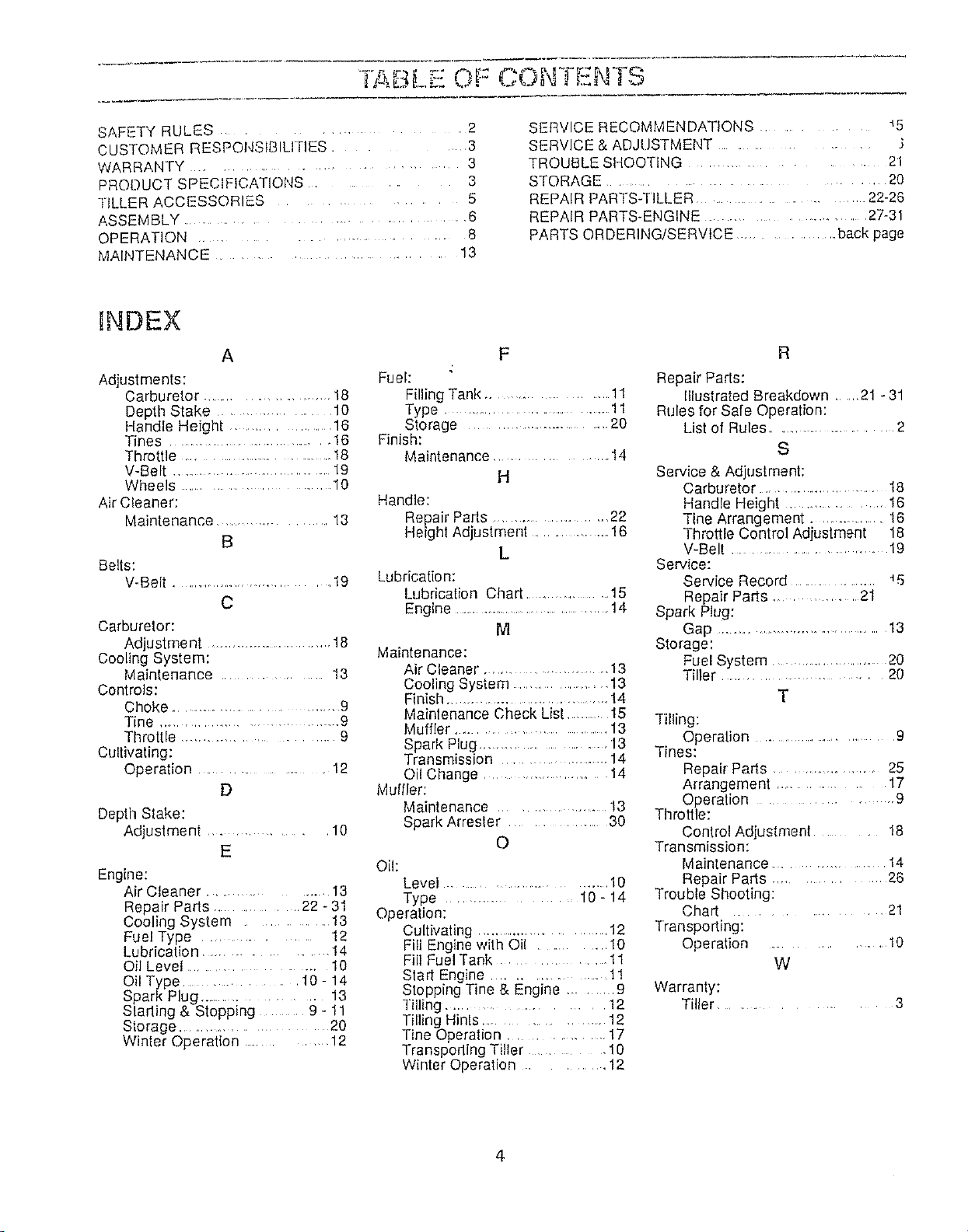
ABL . OF C(aN I=NTS
SAFETY RULES ............ 2
cuSTOMER RESPONStBILI RES ............ 3
3
WARRANTY .............................
PRODUCT SPECIFICATIONS .................. 3
TILLER ACCESSORIES ........... 5
ASSEMBLY .............................................. 6
OPERATION ............................. 8
MAINTENANCE ......................... 13
SERVICE RECOMMENDATIONS .................. 45
SERVICE & ADJUSTMENT ............................ .}
TROUBLE SHOOTING ........................... 21
STORAGE ....................................... 20
REPAIR PARTS-TILLER ..................... 22-26
REPAIR PARTS-ENGINE ......................... 27-31
PARTS ORDERING/SERVICE ................. back page
HNDEX
A
Adjustments:
Carburetor .......................... 18
Depth Stake ................ 10
Handle Height .................... 16
Tines .................................. 16
Throttle ...................................... 18
V-Belt .................................. 19
Wheels ...................................... 10
Air Cleaner:
Maintenance ................ 13
B
Belts:
V-Belt .............................. 19
C
Carburetor:
Adjustment ............................... 18
Cooling System:
Maintenance ............ 13
Controls:
Choke .............................. 9
Tine ................................... 9
Throttle ................................... 9
Cultivating:
Operation .................. 12
D
Depth Stake:
Adjustment ............. 10
E
Engine:
Air Cleaner ............... I3
Repair Parts .......... 22 - 31
Cooling System .............. 13
Fuel Type ....................... 12
Lubrication .............. !4
Oil Level ............................. 10
Oil Type ................. 10- 14
Spark Plug ................. 13
Stading & Stopping .... 9 - 11
Storage .................... 20
Winler Operation ............ 12
Fuel:
Filling Tank ................. 11
Type ................................................! 1
Storage ................................... 20
Finish:
Maintenance .................. 14
H
Handle:
Repair Parts ......................... 22
Heigh! Adjuslment ............. 16
L
Lubrication:
Lubrication Chart ........................15
Engine ..................................... 14
M
Maintenance:
Air Cleaner ....................... 13
Cooling System .................... 13
Finish ...................................... 14
Maintenance Check List ...........15
Muffler ............................ 13
Spark Plug ...................... 13
Transmission ..................... 14
Oil Change ...................... 14
Muffler:
Maintenance ................... 13
Spark Arrester .............. 30
O
Oil:
Level .............................. 10
Type ................. 10 - 14
Operation:
Cultivating ............................ 12
Fill Engine with Oil .......... t0
Fill Fuel Tank ........... 11
Start Engine .............. 1!
Stopping Tine & Engine ...... 9
Tilling .................... 12
Tilling Hinls .............. 12
Tine Operation. 17
Transporting Tiller .................. 10
Winter Operation ............. 12
R
Repair Parts:
Illustrated Breakdown ..... 21 - 31
Rules for Safe Operation:
List of Rules ........................ 2
S
Service & Adjustment:
Carburetor .......................... 18
Handle Height ................. 16
Tine Arrangement .............. 16
Throttle Control Adjustment 18
V-Belt ........................... 19
Service:
Service Record ..................... _5
Repair Parts ................ 21
Spark Plug:
Gap ...................................... 13
Storage:
Fuel System ..................... 20
Tiller ......................... 20
T
Tilling:
Operation ....................... 9
Tines:
Repair Parts ..................... 25
Arrangement .................... 17
Operation .......................... 9
Throttle:
Control Adjustment ............ 18
Transmission:
Maintenance ................... t 4
Repair Parts ............. 26
Trouble Shooting:
Chart .............. 21
Transporting:
Operation ............... 10
W
Warranty:
Tiller ....................... 3
4
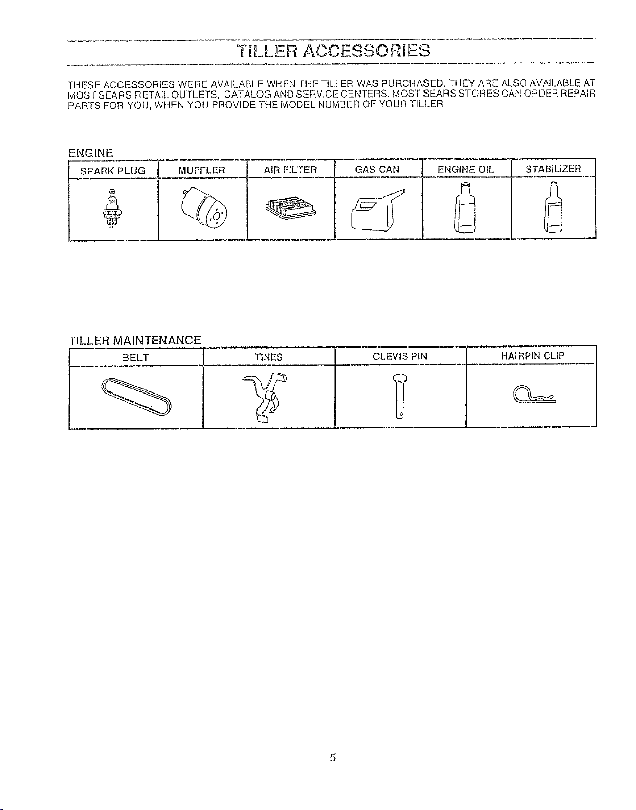
TILLER AOt, ESSOR]Eo
THESE ACCESSORIE_S WERE AVAILABLE WHEN FHE TILLER WAS PURCHASED. THEY ARE ALSO AVAILABLE AT
IviOST SEARS RETAfL OUTLETS, CATALOG AND SERVICE CENTERS. MOST SEARS STORES CAN ORDER REPAIR
PARTS FOR YOU, WHEN YOU PROVIDE THE MODEL NUMBER OF YOUR TILLER
ENGINE
SPARK PLUG MUFFLER
AIR FILTER GAS CAN ENGINE OIL STABILIZER
L
"ILLER MAINTENANCE
BELT TINES
CLEVIS PIN HAIRPIN CLIP
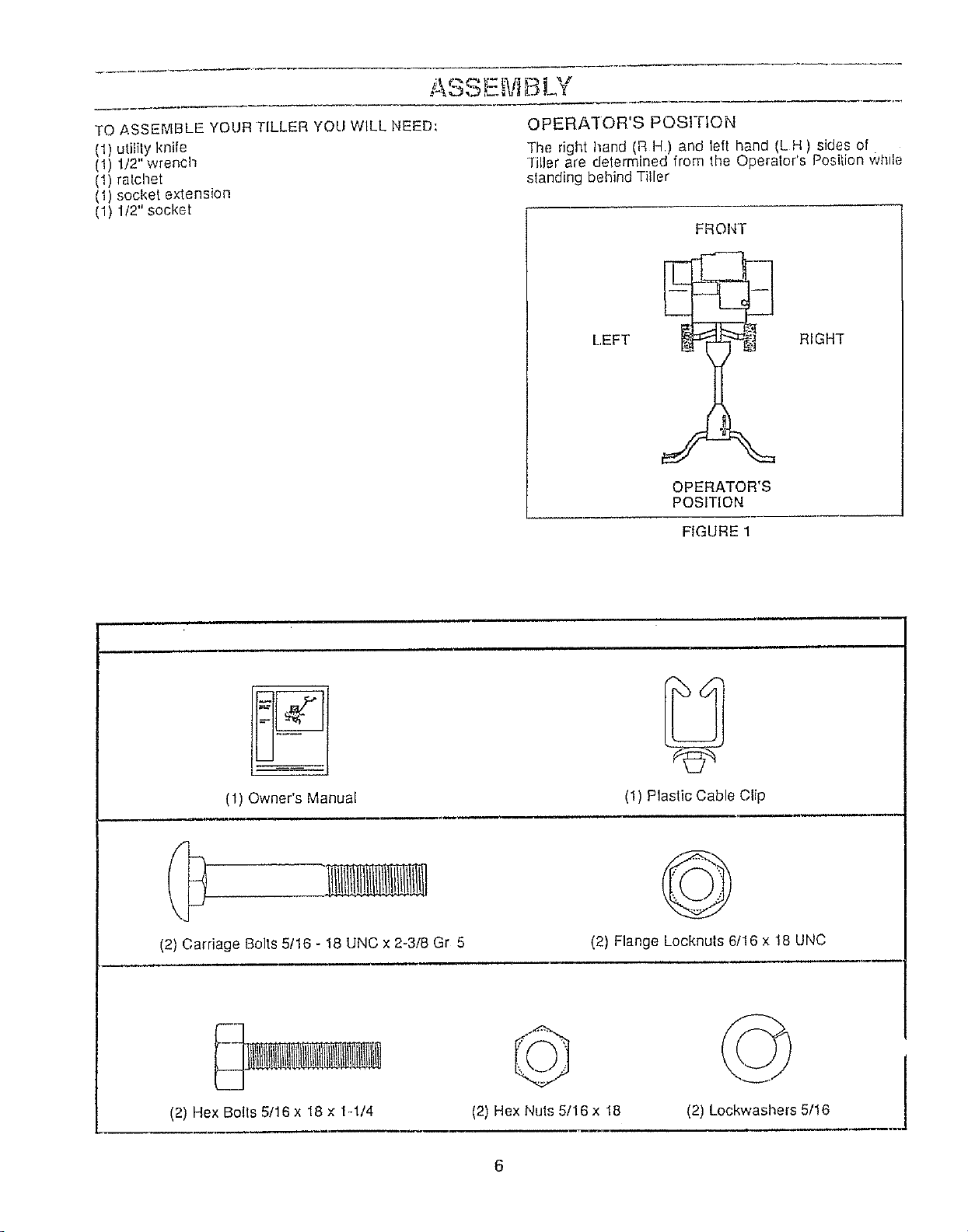
OPERATOR'S POSITION
TO ASSEMBLE YOUR TILLER YOU WILL NEED:
(1) utility knife
(1) 1/2" wrench
(1) ratchet
(1) socket extension
(1) 1/2" socket
]'he right hand (R H.) and left hand (L H ) sides of
*filler are determined from the Operelor's Position while
standing behind Tiller
FROI,,IT
LEFT RIGHT
OPERATOR'S
POSITION
FIGURE 1
(1) Owner's Manual
(2) Carriage Bolts 5!16 - 18 UNC x 2-3/8 Gr 5
(1) Plastic Cable Clip
©
(2) Flange Locknuts 6/16 x 18 UNC
(2) Hex Bolts 5/16 x 18 x 1-1/4
(2) Hex Nuts 5/16x 18
(2) Lockwashers 5/16
!
6
E,.ViBLV
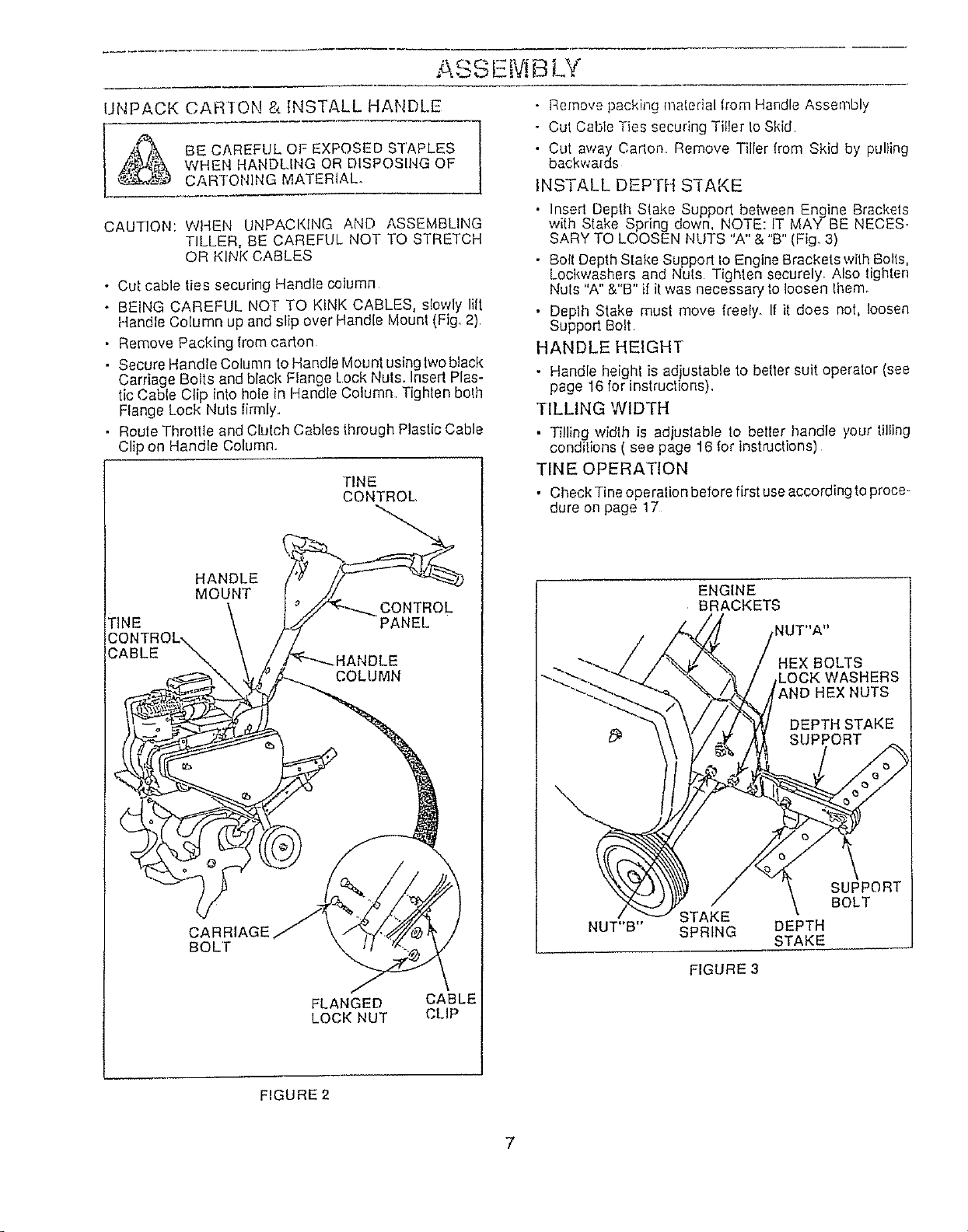
UNPACK CARTON & INSTALL HANDLE
_ BE CAREFUL OF EXPOSED STAPLES
WHEN HANDLING OR DISPOSING OF
CAR'i'ONING MATERIAL°
CAUTION: Wt4EN UNPACKING AND ASSEMBLING
TILLER, BE CAREFUL NOT TO STRETCH
OR KINK CABLES
• Cut cable ties securing Handle column
• BEING CAREFUL NOT TO KINK CABLES, slowly lift
Handle Column up and slip over Handle Mounl (Fig, 2)
• Remove Packing from carton
• Secure HandleColumn to Handle Mounlusinglwoblack
Carriage Bolts and black Flange Lock Nuts, Insert Plas-
tic Cable Clip into hole in Handle Column Tighten bolh
Flange Lock Nuls limlly.
• Roule Throttle and Clulch Cables through Plastic Cable
Clip on Handle Column.
TINE
CONTROL,
HANDLE
MOUNT
CONTROL
TINE PANEL
COLUMN
CARRIAGE
BOLl"
FLANGED CABLE
LOCK NUT CLiP
• Remove packing matedal from Handle Assembly
o Cut Cable Ties securing Tiller to Skid
• Cut away Carlon Remove Tiller lrom Skid by pulling
backwards
INSTALL DEPTH S'I-AKE
• Insed Depth Slake Support beh*zeenEngine Brackets
with Stake Spring down, NOTE: IT MAY BE NECES_
SARY TO LOOSEN NUTS "A" & "B" (Fig. 3)
• Boll DepthStake Support Io Engine Brackets with Bolls,
Lockwashers and Nuls Tighten securely. Also lighten
Nuts "A" &"B" if it was necessary fo loosen Ihem_
• Deplh Stake must move freely, If it does not, loosen
Support Bolt
HANDLE HEIGHT
• Handle height is adjustable to better suit operator (see
page 16 for instructions),
TILLING WIDTH
• Tilling width is adjuslable to beller handle your tilling
conditions ( see page 16 for instructions)
TINE OPERATION
• Check Tine operation before first useaccording to proce-
dure on page 17
ENGINE
BRACKETS
: BOLTS
STAKE
NUT"B" SPRING
FIGURE 3
DEPTH
STAKE
SUPPORT
BOLT
FIGURE 2
7
OPERATION
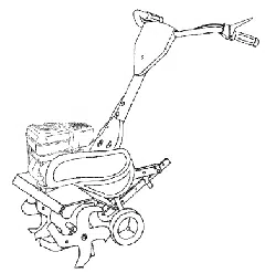
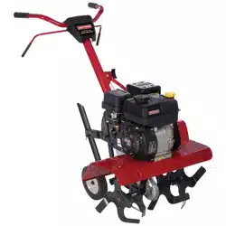
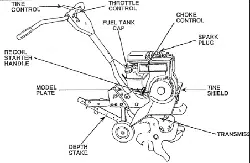
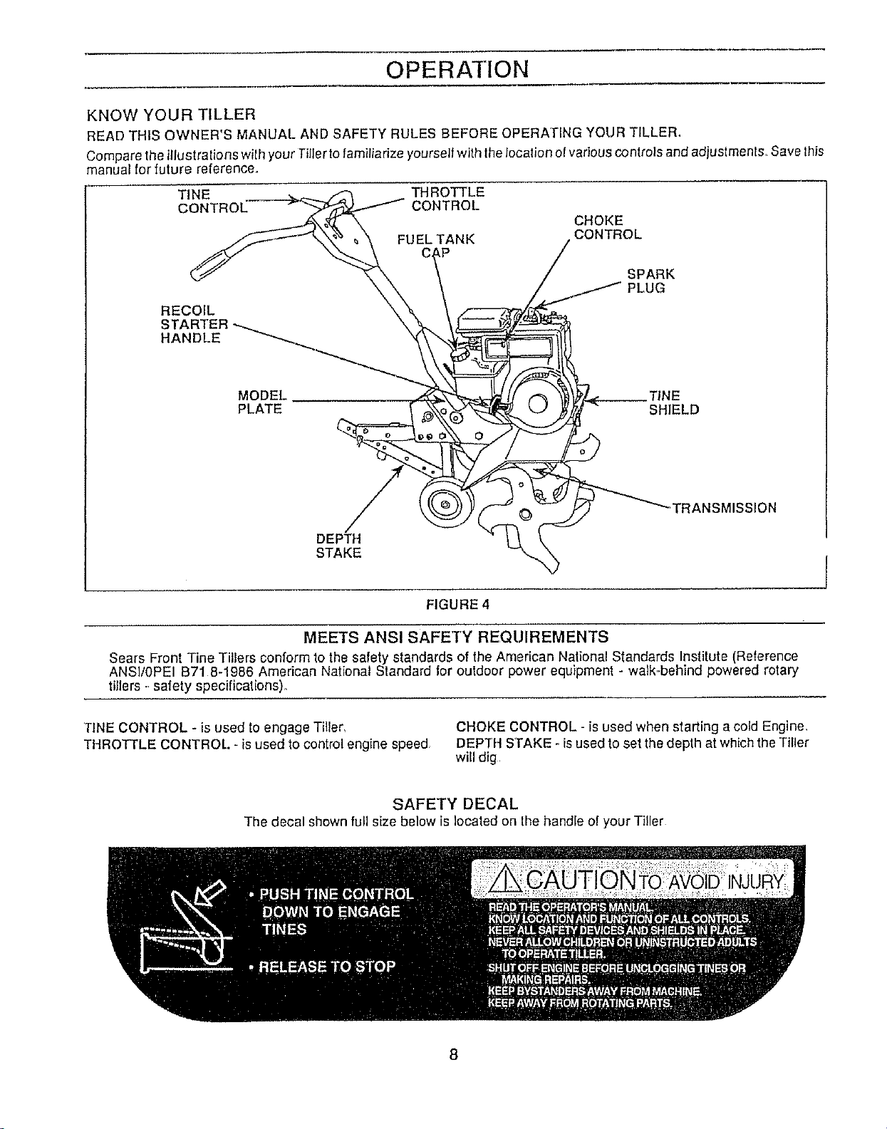
KNOW YOUR TILLER
READ THIS OWNER'S MANUAL AND SAFETY RULES BEFORE OPERATING YOUR TILLER,
Compare the illustrations with your Tillerto familiarize yourself with the location el various controls and adjustment& Save this
manual for future reference.
TINE THROTTLE
CONTROL CONTROL
FUEL TANK
CHOKE
CONTROL
RECOIL
HANDLE
SPARK
JG
MODEl. __TINE
PLATE SHIELD
""TRANSMISSION
DEPTH
STAKE I
FIGURE 4
MEETS ANSI SAFETY REQUIREMENTS
Sears Front Tine Tillers conform to lhe safety standards of the American Nalional Standards Institute (Reference
ANSI/0PEI B718-1986 American National Standard for outdoor power equipment - walk..behind powered rotary
tillers -safety specifications).
TINE CONTROL - is used to engage Tiller,
THROTTLE CONTROL. - is used to control engine speed
CHOKE CONTROL - is used when starting a cold Engine,
DEPTH STAKE - isused to set the depth at which the Tiller
will dig
SAFETY DECAL
The decal shown full size below is Iocaled on the handle of your Tiller
8
OPERATION
....... Fheoperalion of any Tiller can result in foreign objects thrown intotile eyes, which can result in severe
eye damage, Always wear safety glasses or eyeshields before starting you rTiller and while lilling We
recommend Wide Vision Safely Mask for over Ihe speclacles or standard safely glasses, available at
Sears Retail or Catalog Stores
HOW TO USE YOUR TILLER
Know how Io operate all controls before adding fuel and
oil or attempting to start Engine (To stop Engine pIace
Throttle Control in "STOP" position )
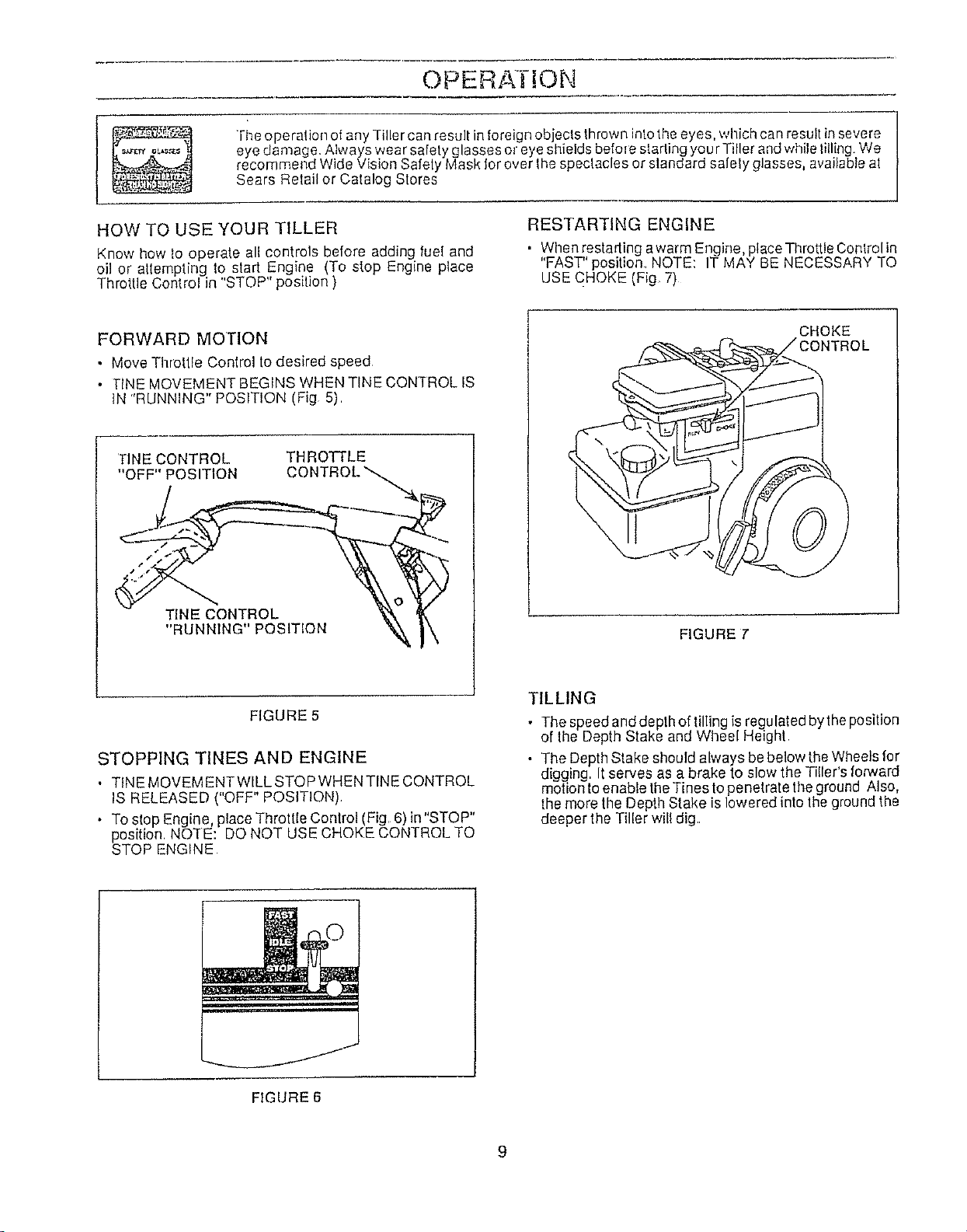
RESTARTING ENGINE
• When restading awarm Engine, ptace Throttle Conlrol in
"FAST" position NOTE: IT MAY BE NECESSARY TO
USE CHOKE (Fig 7)
FORWARD MOTION
• Move Throtlle Control to desired speed
• TINE MOVEMENT BEGINS WHEN TINE CONq-ROL IS
tN "RUNNING" POSITION (Fig 5)
TINE CONTROL
"OFF" POSITION
THROTTLE
CONTROL'_.4_
TINE CONTROL
"RtJNNING" POSITION
CHOKE
ONTROL
FIGURE 7'
FIGURE 5
STOPPING TINES AND ENGINE
• TINE MOVEMENTWILL STOP WHEN TINE CONTROL
IS RELEASED ( OFF POSIT ON),
• To stop Engine, place Throttle Control (Fig, 6) in"STOP"
position, NOTE: DO NOT USE CHOKE CONTROL TO
STOP ENGINE
TILLING
• The speed and depth of tillingis regulated bythe position
of the Depth Stake and Wheel Height
• The Depth Stake should always be below theWheels for
digging, It serves as a brake to slow the Tiller's fonNard
motion toenable the Tines to penetrate theground Also,
the more the Depth Stake is lowered into the ground the
deeper the Tiller will dig
FIGURE 6
OPERATION
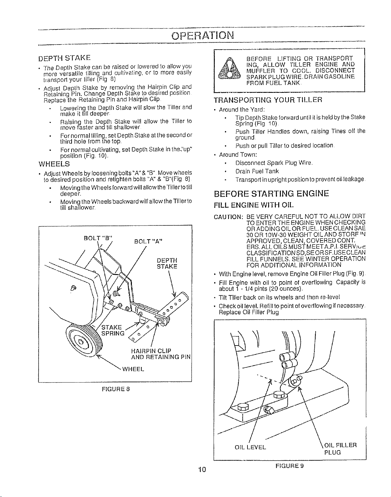
DEPTH STAKE
• "[he Dep "_Sake can be raised or lowered to allow you
more versatile lifting and cultivating, or _omore easily
hanspod your titier (Fig 8)
• Ad ust Depth Stake by removing the Hairpin Clip and
Retan ng Pin. Change Depth Stake to desired position
Replace the Retaining Pin and Hairpin Clip
Lowering the Depth Stake will slow the Tiller and
make it till deeper
Raising the Depth Stake will allow the Tiller to
move faster andtill shallower
For normal lilting, set Depth Stake atthe second or
third hole from the top
For normal cultivating, set Depth Stake inthe"up"
post{ion (Fig 10)
WHEELS
. Adjust Wheels by loosening bolts "A"& "B" Move wheels
to desired position and retighten bolts "A" & "B"(Fig 8)
Moving the Wheels forward will allow the Tiller'iotil!
deeper
Moving the Wheels backward will allow the Tiller to
till shallower
BOLT "B"
BOLT "A"
DEPTH
STAKE
BEFORE LIFTING OR TRANSPORT
ING, ALLOW TILLER ENGINE AND
MUFFLER TO COOL. DISCONNECT
SPAR}( PLUG WIRE, DRAIN GASOLINE
FROM FUEL TANK.
TRANSPORTING YOUR TILLER
• Around the Yard:
Tip Depth Stake forward until it ishefdbythe Stake
Spring (Fig 10)
Push Ti]{er Handles down, raising Tines oil the
ground
Push or pull Tiller to desired location
• Around Town:
Disconnect Spark Plug Wire
Drain Fuel Tank
Transport in upright position to prevent of!leakage
BEFORE STARTING ENGINE
FILL ENGINE WITH OIL
CAUTION: BE VERY CAREFUL NOT TO ALLOW DIRT
TO ENTER THE ENGINE WHEN CHECKING
ORADDING OIL OR FUEL USE CLEAN SAE
30 OR 10W-30 WEIGHT OIL AND STORF rN
APPROVED, CLEAN, COVERED CONT,
ERS. ALL OILS MUST MEET A.P.! SERVJ,-,c
CLASSIFICATION SD,SE ORSF.USECLEAN
FILL FUNNELS. SEE WINTER OPERATION
FOR ADDITIONAL INFORMATION
• With Engine level, remove Engine Oil Filler Plug (Fig 9)
• Fill Engine with oil to point of ovedlowing Capacity is
about 1 - 1/4 pints (20 ounces)_
• Tilt Tiller back on its wheels and then re-level
• Check oil level. Refill to point of ovedlowing if necessary
Replace Oil Filler Plug
HAIRPIN CLIP
AND RETAINING PIN
"WHEEL
FIGURE 8
OIL LEVEL OIL FILLER
PLUG
J
FIGURE 9
10
OPERATION
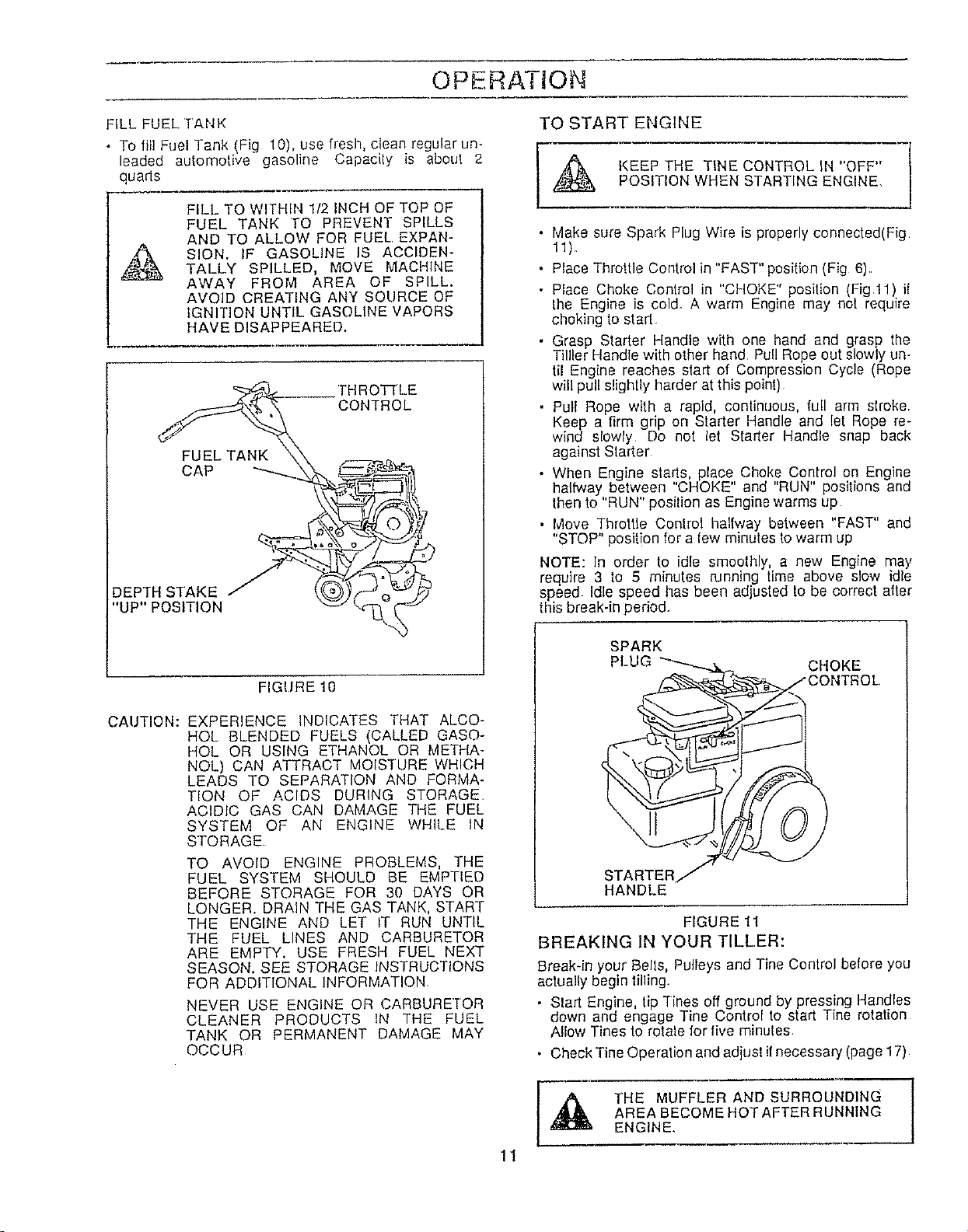
FILL FUEL,TANK
• To fill Fuel Tank (Fig 10), use fresh, clean regular un-
leaded automotive gasoline Capaoily is about 2
quads
,A
FILL TO WITHIN 1/2 INCH OF TOP OF
FUEL TANK TO PREVENT SPILLS
AND TO ALLOW FOR FUEL EXPAN-
SION. IF GASOLINE IS ACCIDEN-
TALLY SPILLED, MOVE MACHINE
AWAY FROM AREA OF SPILL.
AVOID CREATING ANY SOURCE OF
IGNITION UNTIL, GASOLINE VAPORS
;'{AVE DISAPPEARED.
FUEL TANK
CAP
DEPTH STAKE J
"UP" POSITION
THROTILE
CONTROL
CAUTION:
FIGURE 10
EXPERIENCE INDICATES THAT ALCO-
HOL BLENDED FUELS (CALLED GASO-
HOL OR USING ETHANOL OR METHA-
NOL) CAN ATTRACT MOIS'RJRE WHICH
LEADS TO SEPARATION AND FORMA-
TION OF ACIDS DURING STORAGE
ACIDIC GAS CAN DAMAGE THE FUEL
SYSTEM OF AN ENGINE WHILE tN
STORAGE
TO AVOID ENGINE PROBLEMS, THE
FUEL SYSTEM SHOULD BE EMPTIED
BEFORE STORAGE FOR 30 DAYS OR
LONGER. DRAIN THE GAS TANK, START
THE ENGINE AND LET IT RUN UNTIL
THE FUEL LINES AND CARBURETOR
ARE EMPTY, USE FRESH FUEL NEXT
SEASON. SEE STORAGE INSTRUCTIONS
FOR ADDITIONAL INFORMATION
NEVER USE ENGINE OR CARBURETOR
CLEANER PRODUCTS IN THE FUEL
TANK OR PERMANENT DAMAGE MAY
OCCUR
TO START ENGINE
A EEP 'THE TINE CONTROL IN "OFF" /
POSITION WHEN STARTING ENGINE,
J
• Make sure Spark Plug Wire is properly connected(Fig
• Place Throttle Control in "FAST" position (Fig 6).
• Place Choke Conlrol in "CHOKE" position (Fig.ll if
the Engine is cold. A warm Engine may not require
choking to start
• Grasp Starter Handle with one hand and grasp the
Tililer Handle with other hand Pull Rope out slowly un-
til Engine reaches start of Compression Cycle (Rope
will pull slightly harder at this point)
• Pull Rope with a rapid, continuous full arm slroke.
Keep a firm grip on Starter Handle and let Rope re-
wind slowly Do not let Starter Handle snap back
against Starter
• When Engine starts, place Choke Control on Engine
halfway between "CHOKE" and "RUN" positions and
then to "RUN" position as Engine warms up
, Move Throttle Control halfway between "FAST" and
"STOP" position for a few minutes to warm up
NOTE: In order to idle smoothly, a new Engine may
require 3 to 5 minutes running time above slow idle
speed Idle speed has been adjusled to be correct after
this break-in period.
SPARK
PLUG
CHOKE
11
STARTER
HANDLE
FIGURE 11
BREAKING IN YOUR TELLER:
Breakqn your Bells, Pulleys and Tine Control before you
actua!ly begin tilling
• Start Engine tip Tines off ground by pressing Handles
down and engage Tine Control to stad Tne rotation
Allow Tines to rotale for five minu|es
• Check Tine Operation and adjusl itnecessary (page 17)
[,_ THE MUFFLER AND SURROUNDING
AREA BECOME HOT AFTER RUNNING
ENGINE.
OPER. ]-ION
CULTIVATING
A
UNTIL YOU ARE ACCUSTOMED TO
HANDLING YOUR T[LLERI START
ACTUAL FIELD USE WITH THROTTLE
IN SLOW POSITION (MID-WAY BE-
"I-WEEN "FAST" AND "IDLE")
To help Tiller move forward, lift up the Handles slightly
(thus lifting Depth Stake out of ground) To stow down the
Tiller', press down on Handles
II you are straining or Tiller is shaking, the Wheels and
Depth Stake are NOT set properly in the soil being tilled
The proper setting of the Wheels and Deptll Stake is
through trial and error and depends upon the soil condition.
The harder orwetter the ground, the slower the engine and
t ne speed needed Under these poor condi ions, at'tast
speed the Tiller will run and jump over lhe ground).
A properly adjusted Tiller wilt dig with little e(fort from the
operalor
TILLING HINTS
• Tilling is digging into, turning over, and breaking up
packed soil before planting, Loose, unpacked soil helps
root growlh Best tilling depth is 4" to 6" A Tiller will also
clearthe soil of unwanted vegetation The decomposition
of this vegetable matter enriches the soil. Depending on
the climate (rainfall and wind), it may be advisable 1otill
the soil at the end of the growing season to further
condition the soil
, Soil conditions are important for proper tilling+Tines will
not readily penetrate dry, hard soil which may contribute
to excessive bounce and difficult handling of your't.iller.
Hard soil should be moistened before tilling; however,
extremely wet soil will "ball-up" or clump during tilling.
Wait until the soil is less wet in order to achelve the best
results. When tilling in the fall, remove vines and long
_rass to prevent them from wrapping around the "Fine
haft and slowing your tilling operation
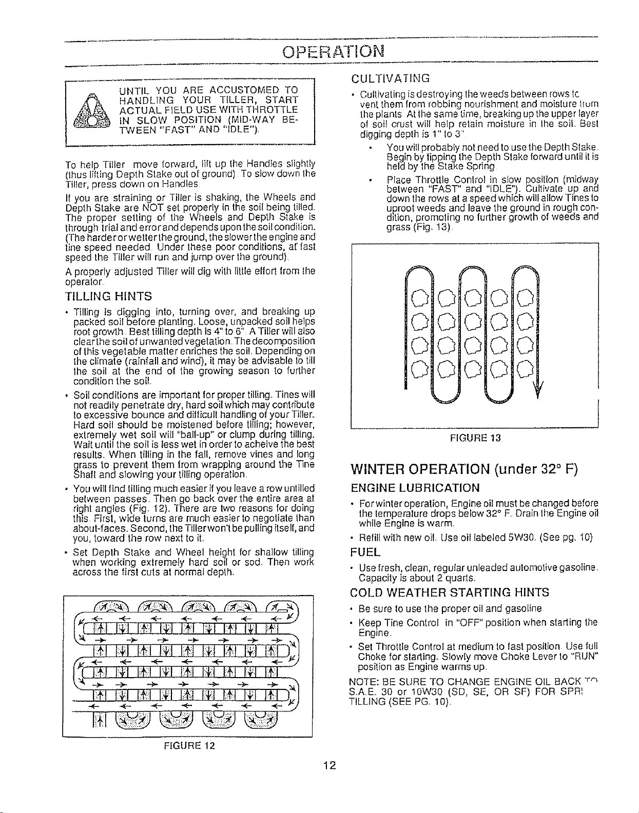
• You wil! find tilling much easier ifyou leave a row untilled
between passes Then go back over the entire area at
right angles (Fig. 12)+ There are two reasons for doing
this First, wide turns are much easier to negotiate than
about-faces Second, the Tillerwon'l bepulling itself,and
you, toward the row next to it.
• Set Depth Stake and Wheel height for shallow tilling
when working extremely hard soil or sod. Then work
across the first cuts at normal depth.
,+,,+,,,+:,
!+:t. I;+tP:+,I D I
_4- -<- .<- ÷ ÷ ÷ 4- :j
[._C-I}l I::fl H':I Ii{I 114"!I_lq4,1 N,t 14';I
• 14':1I+1 I:_1I:_JI:_;IB'T I:+! 14;I!4':,1)_J
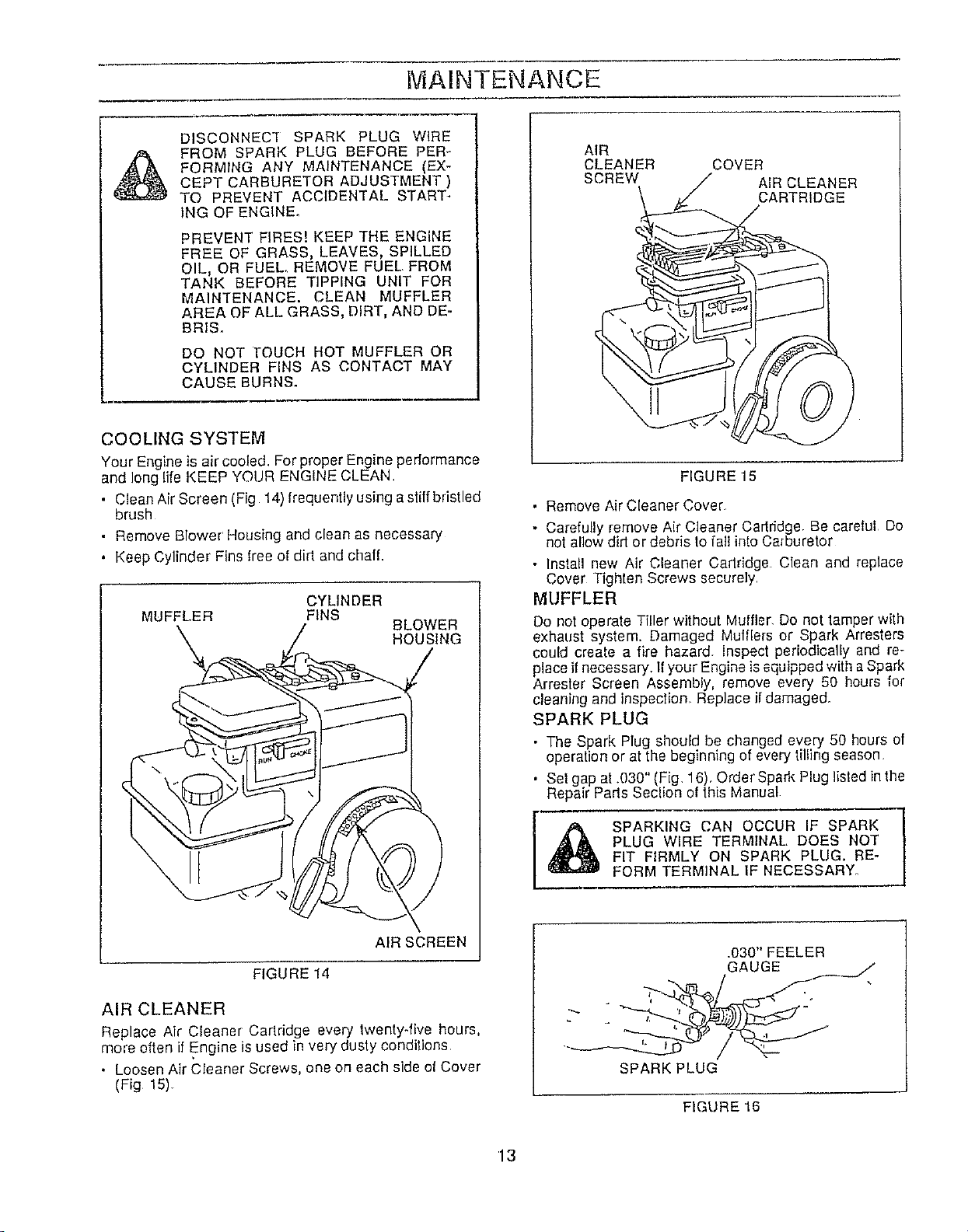
• Cultivating isdestroying the weeds between rows tc
vent them from robbing nourishment and moislure hum
the plants Atthe same time, breaking up theupper layer
of soil crust will help retain moisture in the soil Best
digging depth is 1" to 3"'
You will probably not need to use the Depth Stake.
Begin by tippingthe Depth Stake forward until it is
held by the Stake Spring
Place Throttle Conlrol in slow position (midway
between "FAST" and "IDLE"). Cultivate up and
down file rows at a speed which will allow Tines to
uproot weeds and leave the ground in rough con-
d_tion, promoting no farther growth of weeds and
grass (Fig+ 13)
\ r
FIGURE 13
WINTER OPERATION (under 32° F)
ENGINE LUBRICATION
• Forwinteroperation, Engine oil must be changed belore
the temperature drops below 32" F Drain the Engine oil
while Engine is warm
• Refill wilh new oil. Use oil labeled 5W30. (See pg 10)
FUEL
• Usefresh, clean, regularunleaded automotive gasoline.
Capacity is about 2 quads.
COLD WEATHER STARTING HINTS
• Be sure to use the proper oil and gasoline
• Keep Tine Control in "OFF" position when starling the
Eng+ne.
• Set Throltle Control at medium to fast position Use full
Choke for starling. Slowly move Choke Lever to "RUN"
position as Engine warms up.
NOTE: BE SURE TO CHANGE ENGINE OIL BACK "r,'_
S.AE. 30 or 10W30 (SD, SE, OR SF) FOR SPRI
TILLING (SEE PG. 10).
FIGtJRE 12
12
MAINTENANCE
DISCONNEC'f SPARK PLUG WIRE
FROM SPARK PLUG BEFORE PER-
FORMING ANY MAINTENANCE (EX-
CEPT CARBURETOR ADJUSTMENT )
TO PREVENT ACCIDENTAL START-
ING OF ENGINE.
PREVENT FIRES! KEEP THE ENGINE
FREE OF GRASS, LEAVES, SPILLED
OIL, OR FUEL. REMOVE FUEL. FROM
TANK BEFORE TIPPING UNIT FOR
MAINTENANCE. CLEAN MUFFLER
AREA OF ALL GRASS, DIRT, AND DE-
BRIS.
DO NOT ]-OUCH HOT MUFFLER OR
CYLINDER FINS AS CONTACT MAY
CAUSE BURNS.
COOLING SYSTEM
Your Engine is air cooled. For proper Engine pedormance
and long life KEEP YOUR ENGINE CLEAN.
•Clean Air Screen (Fig 14) frequently using a stiff bristled
brush
• Remove Blower' Housing and clean as necessary
• Keep Cylinder Fins free of dirt and chaff.
CYLINDER
MUFFLER FINS
BLOWER
HOUSING
AIR SCREEN
FIGURE 14
AIR CLEANER
Replace Air Cleaner Cartridge every twenty-five hours,
more often if Engine is used in very dusty conditions
• Loosen Air Cleaner Screws, one on each side ol Cover
(Fig 15).
AIR
CLEANER
SCREW
COVER
AIR CLEANER
CARTRIDGE
FIGURE 15
• Remove Air Cleaner Cover
• Carefully remove Air Cleaner Cartridge. Be careful Do
not allow did or debris to fall into Carburetor
• Install new Air Cleaner Cadridge Clean and replace
Cover Tighten Screws securely
MUFFLER
Do not operate Tiller without Muffler. Do not tamper with
exhaust system. Damaged Mufflers or Spark Arresters
could create a fire hazard. Inspect periodically and re-
place if necessary. If your Engine is equipped with aSpark
Arrester Screen Assembly, remove every 50 hours for
cleaning and inspeclion_ Replace if damaged.
SPARK PLUG
• The Spark Plug should be changed every 50 hours of
operation or at the beginning of every tilling season.
• Set gap at .030" (Fig, 16), Order Spark Plug listed in the
Repair Pads Seclion of this Manual
SPARKING CAN OCCUR IF SPARK
PLUG WIRE TERMINAL, DOES NOT
FIT FIRMLY ON SPARK PLUG. RE-
FORM TERMINAL IF NECESSARY.
.030" FEELER
GAUGE f_
/--%_
SPARK PLUG
FIGURE 16
13
MAINTENANCE
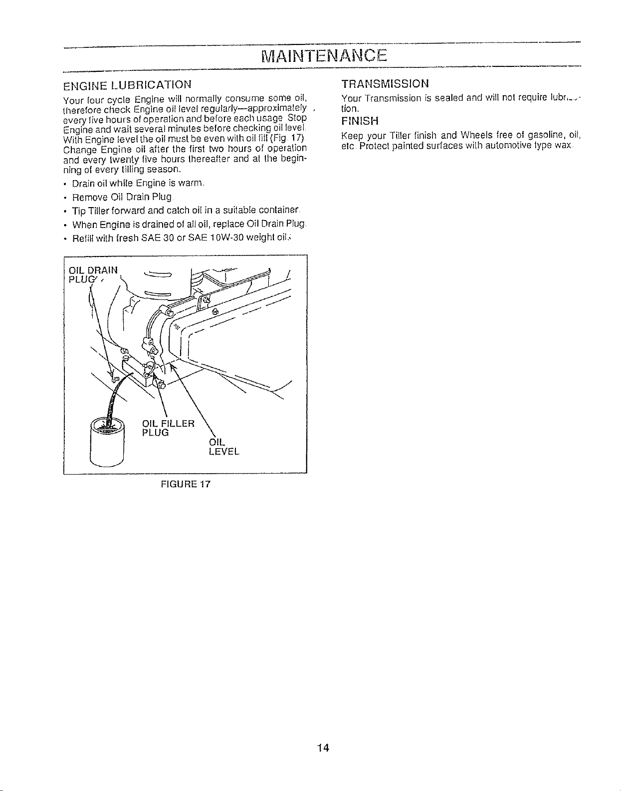
ENGINE LUBRICATION
Your four cycle Engine will normally consume some oil,
therefore check Engine oil level regulady--approximalely ,
every live hours of operalion and before each usage Stop
Engine and wait several minutes before checking oil level
With Engine level the oil must be even with oil fill (Fig 17)
Change Engine oil after the first two hours of operation
and every twenty five hours thereafter and at the begin-
ning of every tilling season.
• Drain oil while Engine is warm
• Remove Oil Drain Plug
• Tip Tiller forward and catch oil in a suitable container
• When Engine is drained of all oil, replace Oil Drain Plug.
• Refill with fresh SAE 30 or SAE 10W-30 weight oil_
TRANSMISSION
Your Transmission is sealed and will nol require lebr,_.,
tion,
FINISH
Keep your Tiller finish and Wheels flee of gasoline, oil,
elc Protect painted surlaces with automotive type wax
OIL FILLER
PLUG
OIL
LEVEL
FIGURE 17
14
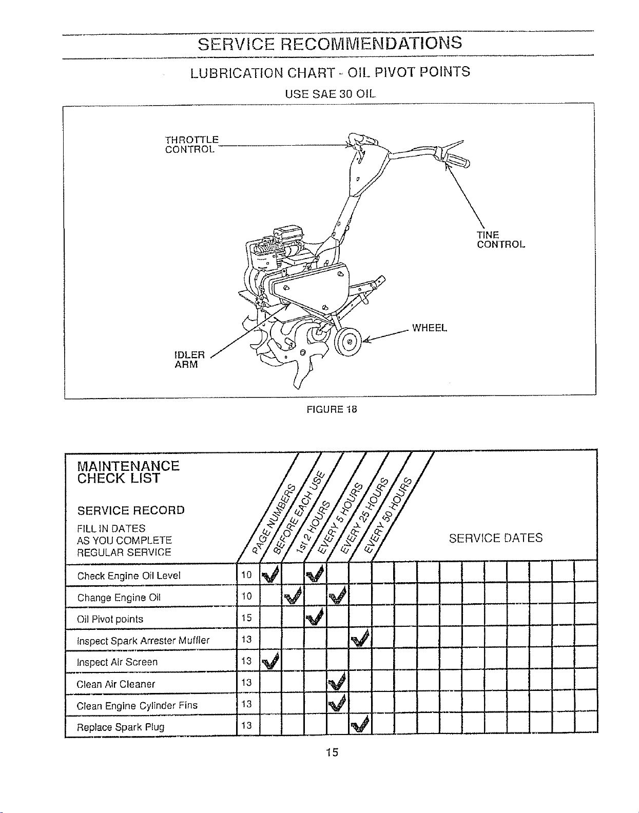
SERVICE RECOMMENDATIONS
LUBRICATION CHART ,-OIL PIVOT POINTS
USE SAE30 OIL
THROT'[LE
CONTROL.
TINE
CON'rROL
IDLER
ARM
FIGURE 18
10
10
15
13
13
13
13
13
15
SERVICE AND ADJUSTMENTS
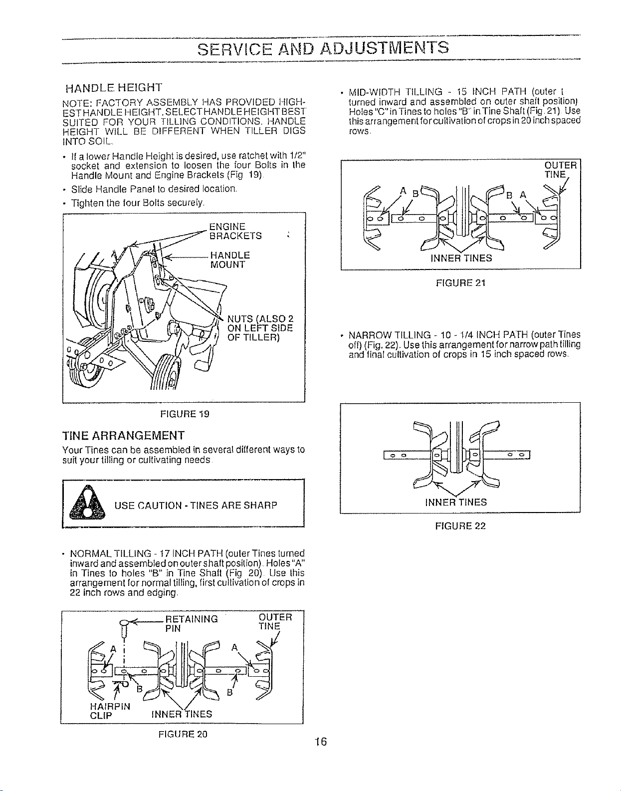
HANDLE HEIGHT
NOTE: FACTORY ASSEMBLY HAS PROVIDED 141GH-
ESTHANDLE HEIGHT, SELECTHANDLE HEIGHT BEST
SUITED FOR YOUR TILLING CONDITIONS, HANDLE
HEIGHT WILL BE DIFFERENT WHEN TILLER DIGS
INTO SOIL
• tfalower Handle Height is desired, use ratchet with 112"
socket and extension to loosen Ihe four Bolts in the
Handle Mount and Engine Brackels (Fig 19)
• Slide Handle Panel to desired location
• Tighten the four Bolts securely
ENGINE
_ BRACKETS
\_k\\JI!l \ [/_ _ _ , NUTS(ALSO2
_-_-J_l__P'," tL',N _ ON LEFT SIDE
OPT,LLER
• MID-WIDTH TILLING - 15 INCH PATH (outer [
turned inward and assembled on outer shaft positionJ
Holes "C" in Tines to holes "B'"inTine Shaf! (Fig 21) Use
this arrangement forcultivation of crops in 20 inchspaced
rOWS
OUTER
TINE
AB B A
INNER TINES
FIGURE 21
• NARROW TILLING - 10 -1/4 INCH PATH (outer Tines
off) (Fig. 22). Use this arrangement for narrow pathtilling
and final cultivation of crops in 15 inch spaced rows
FIGURE 19
TINE ARRANGEMENT
Your Tines can be assembled in several different ways to
suit your tilling or cultivating needs
[I_ USE CAUTION -TINES ARE SHARP
[o o_ o ol
INNER TINES
FIGURE 22
• NORMAL TILLING - 17 INCH PATH (outer Tines turned
inward and assembled on outer shaft position) Holes"A"
in Tines lo holes "B" in Tine Shall (Fig 20) Use this
arrangemenl for normal tilling, first cultivation of crops in
22 inch rows and edging.
RETAINING OUTER
PIN TINE
HAIRPIN \/
CLIP INNER TINES
FIGURE 20
16

SERVICE AND ADJUSTMENTS
• EDGING - 9 - 5/8 INCH PATH (inner Tines off, ouler
Tines assembled on innermost shalt position). HoIes "A'
in Tines to holes "D" in Tine Shalt (Fig. 23) Use this ar-
rangement for edging and first cultivation of crops in 15
inch spaced rows
DISCONNECt SPARK PLUG WIRE
WHEN CHECKING TINE CONTROL
OPERATION.
Fo o -- Jo---6--_q
-OUTER TINE
FIGURE 23
• NARROW CULTIVATING - 12 - 1/2 INCH PATH (inner
Tines off, outer Tines assembled on middle shaft posi-
tion) Holes "A" in Tines to holes "E" in Tine Shaft (Fig
24) Use this arrangement for cultivating narrow rows
A
E
A
o O O o
'OUTER TINE
FIGURE 24
NOTE: OUTER TINES CAN BE REVERSED - TINES
TURNED OUTWARD WILL THROW DIRT OUTWARD
TINES TURNED INWARD WILL THROW DIRT INWARD.
FOR CULTIVATING SMALL CROPS, EDGING OR
HILLING, ALL YOU NEED "TOREMEMBER AS YOU RE-
ASSEMBLE TINES IS THAT WHEN LOOKING AT THE
RIGHT SIDE OF THE TILLER, "R"s STAMPED ONTINES
WILL BE VISIBLE, AND ON THE LEFT SIDE OF THE
TILLER, STAM PED"L"s WILL SHOW. SHARPENED TINE
EDGES WILL ROTATE FORWARD FROM ABOVE
TINE OPERATION CHECK
• With Tine Control in "OFF" (UP) position, Tine Conlrol
Lever should be against Tine Control Body (Fig 25) If
not, loosen Clip and pull Tine Control Cable up Retighten
Clip If adjustments are made, make sure Tines do not
rotate when Tine Control is in 'OFF" position See next
step
, Wilh Tine Control in 'OFF" (UP) position, push Tiller
Handles down so Tines clear the ground Pull Slader
Handle Tines should not rotate If they do, loosen Clip
and push Tine Control Cable down Retighten Clip and
test Readjust if necessary
• With Tine Control in "RUNNING" position, push Tiller
Handles down so Tines clear the ground Pull Starter
Handle - Tines should rotate lorward If lhey do not,
loosen Clip and pull Tine Control Cable up Retighten
Clip and test Readjust if necessary
TINE CONTROL BODY
"OFF" POSITION
TINE CONTROL
"RUNNING
POSITION
;ONTROL
CABLE
SPARK
PLUG
STARTER
HANDLE
FIGURE 25
17
SERVICE AND ADJUSTMENT
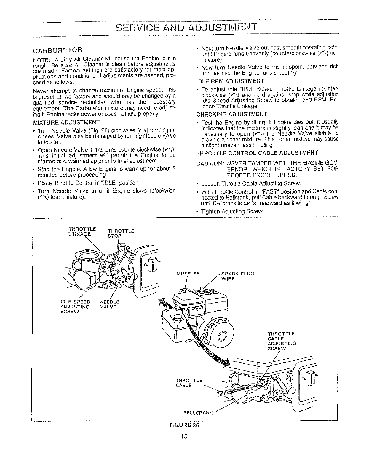
CARBURETOR
NOTE: A dirly Air Cleaner will cause tile Engine to run
rough, Be sure Air Cleaner is clean before adjustments
are made Faclory seltings are satisfactory for most ap-
plications and condilions If adjuslments are needed, pro-
ceed as Iollows:
Never attempt to change maximum Engine speed. This
is preset at the factory and should only be changed by a
qualified service technician who has the necessary
equipment The Carburetor mixture may need re-adjust-
ing if Engine lacks power or does not idle properly,
MIXTURE ADJUSTMENT'
• Turn Needle Valve (Fig, 26) clockwise (,,_) until it just
closes. Valve may be damaged by turning Needle Valve
in too far
• Open Needle Valve 1-1/2 turns counterclockwise 0_)
This initial adjustment will permit the Engine to be
started and warmed up prior to final adjustment
• Start the Engine_ Allow Engine to warm up for about 5
minutes before preceeding_
• Place Throttle Control in "IDLE" position
• Turn Needle Valve in until Engine slows (clockwise
(,"--()lean mixture)
THROTTLE THROTTLE
LINKAGE STOP
• Next turn Needle Valve out past smooth operating poiN
until Engine runs unevenly (counterclockwise (:,_',)rk
mixlure)
• Now lurn Needle Valve to the midpoint between rich
and lean so the Engine runs smoothly
IDLE RPM ADJUSTMENT
• To adjust Idle RPM, Rotate Throttle Linkage counter-
clockwise F'_) and hold against stop while adjusting
Idle Speed Ad ustng Screw _oobtain 1750 RPM Re-
lease Throttle Linkage
CHECKING ADJUSTMENT
• Test the Engine by tilling If Engine dies out, it usually
indicates that the mixture is slightly lean and it may be
necessary to open (_"', the Needle Valve slightly to
provide a richer mixture This richer m xture may cause
a slight unevenness in idling
THROTTLE CONTROL CABLE ADJUSTMENT
CAUTION: NEVER TAMPER WITH THE ENGINE GOV-
ERNOR, WHICH IS FACTORY SET FOR
PROPER ENGINE SPEED
• Loosen Throttle Cable Adjusting Screw
• Wilh Throttle Conlrol in "FAST" position and Cable con-
nected lo Bellcrank, pull Cable backward through Screw
until Bellcrank is as far rea_ard as itwill go
• Tighten Adjusting Screw
MUFFLER PLUG
WIRE
IDLE SPEED NEEDLE
ADJUSTING VALVE
SCREW
THROTTLE
CABLE
THROTTLE
CABLE
ADJUSTING
SCREW
FIGURE 26
18
SERVMCE AND ADJUSTMENTS
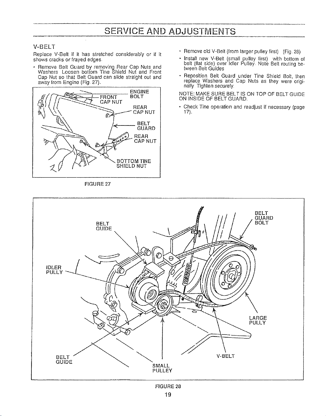
V-BELT
Replace V-Belt if it has stretched considerably or if it
shows cracks or frayed edges.
• Remove Belt Guard by removing Rear Cap Nuts and
Washers Loosen bottom Tine Shield Nut and Front
Cap Nut so that Belt Guard can slide straight out and
away from Engine (Fig 27)_
ENGI.E
FRONT BOLT
j//! CAPNUT
:l_J (, l! _'_ .----"REAR
'_"X\ I_ BELT
_ / _ REAR
• Remove old V-Belt (from larger pulley first) (Fig, 28)
• Install new V-Belt small pulley first) with bottom of
be t (f at s de) over Id er Pulley Nole Belt routing be-
tween Belt Guides
• Reposition Belt Guard under Tine Shield Boll, lhen
replace Washers and Cap Nuls as they were origi-
nally Tighten securely
NOTE: MAKE SURE BELT IS ON TOP OF BELTGUIDE
ON INSIDE OF BELT GUARD°
• Check Tine operation and readjust if necessary (page
17).
FIGURE 27
BELT
GUIDE
\
BELT
GUARD
BOLT
IDLER
PULLY
LARGE
PULLY
BELT
GUIDE
SMALL
PULLEY
V-BELT
FIGURE 28
19
STORAGE
STORAGE
Keep your Tiller in a weatherproof, dry building To avoid
Engine problems, the fuel system should be emptied be-
fore storage of 30 days or longer
• Drain Fuel Tank; run Engine until gasoline in Carbure-
tor is used
, While Engine is still warm, drain oil from Engine. Refill
with [resh oil
• Remove Spark Plug; pour one half ounce of clean er_-
gine oil into cylinder. Pull Stader Handle slowly several
times to distribute oil Replace Spark Plug
, Clean entire Tiller, especially Cylinder Fins, Blower
Rousing and Air Screen Tighten all bolts and nuts(
Gasoline stored for several months wilt lose its volatili
(ability to burn effectively); therefore, always use up gaso-
line at the end of the season Do not store, spill, or use
gasoline near an open fiam_ or devices such as a slove,
furnace, or water heater which utilize a pilol light or de-
vices that can create a spark.
CAUTION:
IT IS IMPORTANT TO PREVENT GUM
DEPOSITS FROM FORMING IN ESSEN-
TIAL FUEL SYSTEM PARTS SUCH AS THE
CARBURETOR, FUEL FILTER, FUEL
HOSE, OR TANK DURING STORAGE.
ALSO, EXPERIENCE INDICATES THAT
ALCOHOL BLENDED FUELS (CALLED
GASOHOL OR USING ETHANOL OR
METHANOL) CAN ATTRACT MOISTURE
WHICH LEADS TO SEPARATION AND
FORMATION OF ACIDS DURING STOR-
AGE. ACIDIC GAS CAN DAMAGE THE
FUEL SYSTEM OF AN ENGINE WHILE IN
STORAGE
2O
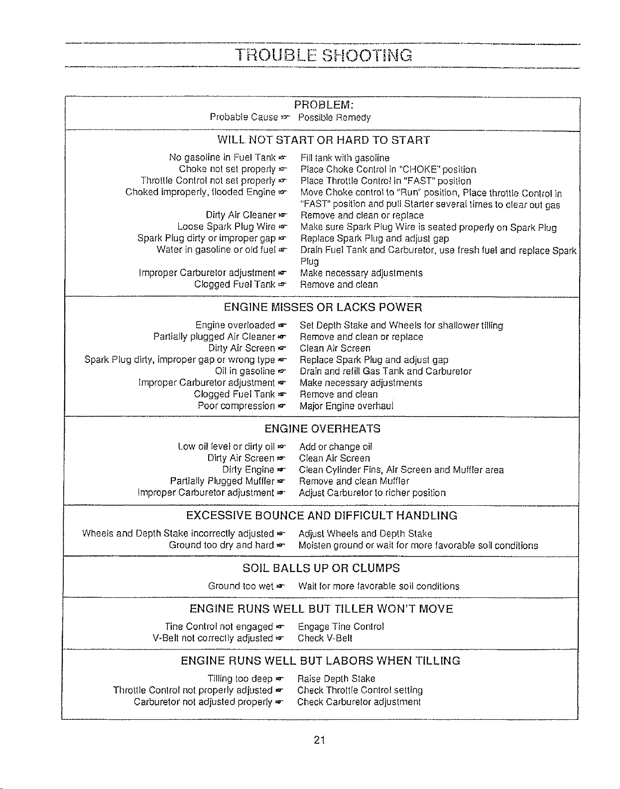
t. OUBLL SHOOTDNc
PROBLEM:
Probable Cause,_,- Possible Remedy
WILL NOT START OR HARD TO START
No gasoline in Fuel Tank
Choke not set properly
Throttle Control not set properly
Choked improperly, l!ooded Engine =,-
Didy Air Cleaner
Loose Spark Plug Wire
Spark Plug dirty or improper gap _"
Water in gasoline orold fuel
Improper Carburelor adjustment ,,e--
Clogged Fuel Tank
Fill tank with gasoline
Place Choke Control in "CHOKE" position
Place Throltle Control in "FAST" position
Move Choke control to "Run" position, Place throttle Control in
"FAST" position and pull Starter several times to clear out gas
Remove and clean or replace
Make sure Spark Plug Wire is seated properly on Spark Plug
Replace Spark Plug and adjust gap
Drain Fuel Tank and Carburetor, use fresh fuel and replace Spark
Plug
Make necessary adjustments
Remove and clean
ENGINE MISSES OR LACKS POWER
Engine overloaded _,-
Partially plugged Air Cleaner
Didy Air Screen
Spark Plug dirty, improper gap or wrong type
Oil in gasoline ,_
Improper Carburetor adjustment ,_
Clogged Fuel Tank
Poor compression ,_-
Set Depth Stake and Wheels for shallower tilling
Remove and clean or replace
Clean Air Screen
Replace Spark Plug and adjust gap
Drain and refill Gas Tank and Carburelor
Make necessary adjustments
Remove and clean
Major Engine overhaul
ENGINE OVERHEATS
Low oil level or dirty oil ,,_'
Dirly Air Screen
Dirty Engine
Partially Plugged Muffler
improper Carburetor adjustment _-
Add or change oil
Clean Air Screen
Clean Cylinder Fins, Air Screen and Muffler area
Remove and clean Muffler
Adjust Carburetor 1oricher position
EXCESSIVE BOUNCE AND DIFFICULT HANDLING
Wheels and Depth Stake incorrectly adjusted ,,_ Adjust Wheels and Depth Stake
Ground too dry and hard _- Moisten ground or wait for more favorable soil conditions
SOIL BALLS UP OR CLUMPS
Ground too wet ,_- Wait for more favorable soil conditions
ENGINE RUNS WELL BU'I TILLER WON'T MOVE
Tine Control not engaged _ Engage Tine Control
V-Bell not correctly adjusted _ Check V-Bell
ENGINE RUNS WELL BUT LABORS WHEN TILLING
Tilling loo deep _ Raise Depth Slake
Throt!le Control not properly adjusted _- Check rhroltle Conlro! setting
Carburetor not adjusted properly _,- Check Carburetor adjustment
21
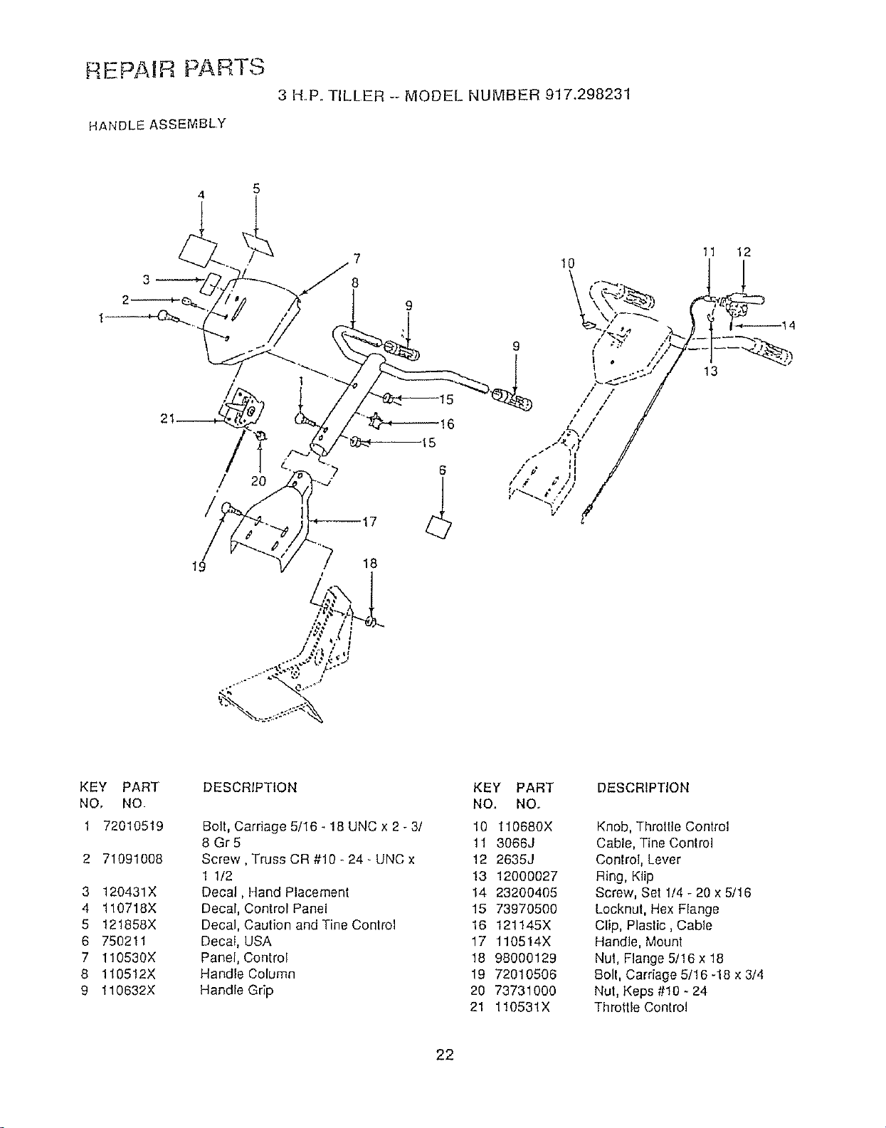
REPAHR PARTS
3 F'LP° TILLER -- MODEL NUMBER 917.298231
HANDLE ASSEMBLY
19
5
20
11
13
12
KEY PART
NO, NO.
1 72010519
2 71091008
3 120431X
4 110718X
5 121858X
6 750211
7 110530X
8 110512X
9 110632X
DESCRIPTION
Bolt, Carriage 5/16 - 18 UNC x 2 - 3/
8 Gr5
Screw, Truss CR #10- 24- UNC x
1 1/2
Decal, Hand Placement
Decal, Control Panel
Decal, Caution and Tine Control
Decal, USA
Panel, Control
Handle Column
Handle Grip
KEY PART
NO. NO.
10 110680X
11 3066J
12 2635J
!3 12000027
14 23200405
15 73970500
16 121145X
17 110514X
18 98000129
19 '72010506
20 73731O0O
21 110531X
DESCRIPTION
Knob, Throttle Control
Cable, Tine Control
Controt, Lever
Ring, Klip
Screw, Set 1/4 - 20 x 5/16
Locknut, Hex Flange
Clip, Plastic, Cable
Handle, Mount
Nut, Flange 5/16 x 18
Bolt, Carriage 5/16 -18 x 3/4
Nut, Keps #10 - 24
Throttle Control
22
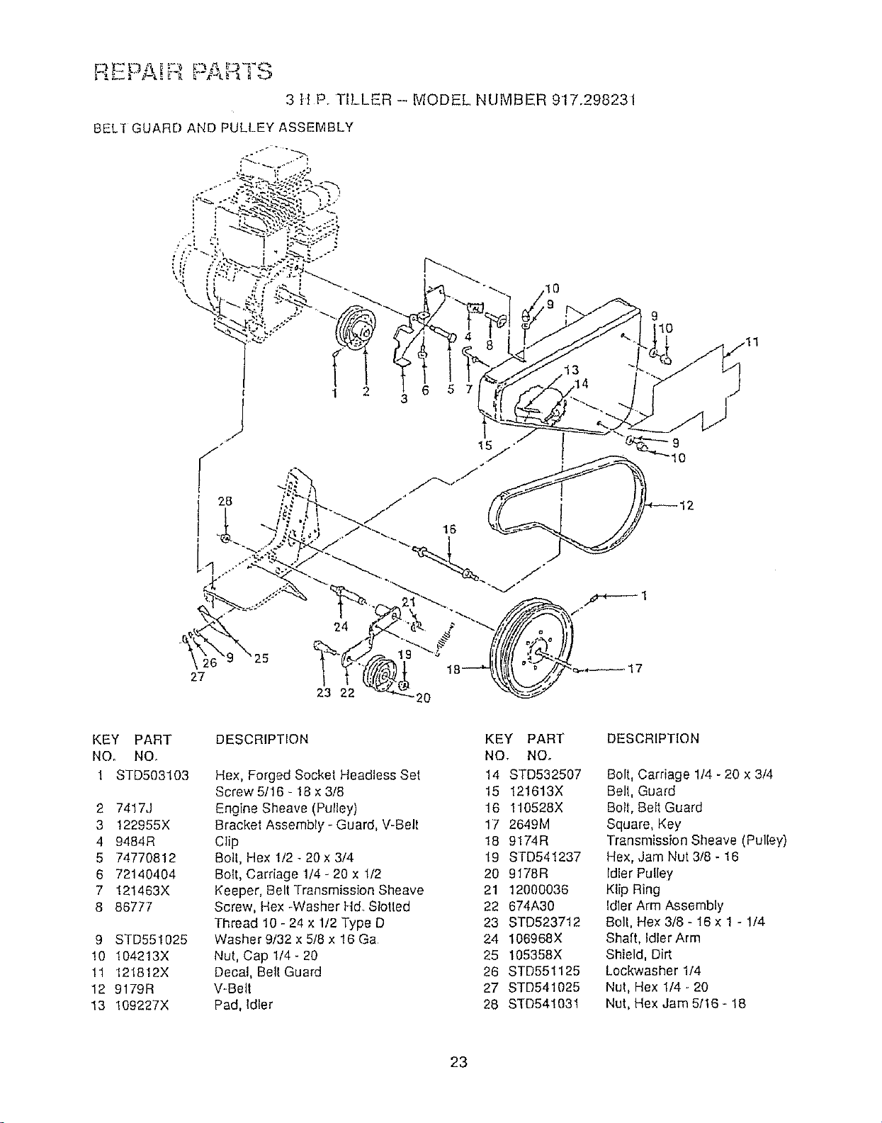
REPAi ....."
3 tiP. TILLER --, MODEL NUMBER 917.298231
BELT GUARD AND PULLEY ASSEMBLY
10
I
S
28
2
23 22
20
J
KEY PART
NO. NO.
1 STD503103
2 7417J
3 !22955X
4 9484R
5 74770812
6 72140404
7 !21463X
8 86777
9 STD551025
10 104213X
11 121812X
12 9179R
13 108227X
DESCRIPTION
Hex, Forged Socket Headless Set
Screw 5/16 - 18 ×3/8
Engine Sheave (Pulley)
Bracket Assembly - Guard, V-Belt
Clip
Boll, Hex !/2 - 20x 3/4
Bolt, Carriage 1/4 - 20 x 1/2
Keeper, Belt Transmission Sheave
Screw, Hex -Washer Ftd Slotted
Thread 10 - 24 x 1/2 Type D
Washer 9/32 x 5/8 x 16 Ga
Nut, Cap 1/4- 20
Decal, Belt Guard
V-Belt
Pad, Idler
KEY PART
NO. NO.
14 STD532507
15 121613X
16 110528X
1'7 2649M
18 9174R
19 STD54t237
20 9178R
21 12000036
22 674A30
23 STD523712
24 106968X
25 105358X
26 STD551125
27 STD541025
28 STD54!031
DESCRIPTION
Bolt, Carriage 1!4 - 20 x 3/4
Bell, Guard
Bolt, Belt Guard
Square, Key
Transmission Sheave (Pulley)
Hex, Jam Nut 3/8 - 16
Idler Pulley
Klip Ring
Idler Arm Assembly
Belt, Hex 3/8 - 16 x 1 - 1/4
Shaft, Idler Arm
Shield, Dirt
Lockwasher 1/4
Nut, Hex 1/4 -,20
Nut, Hex Jam 5116- 18
23
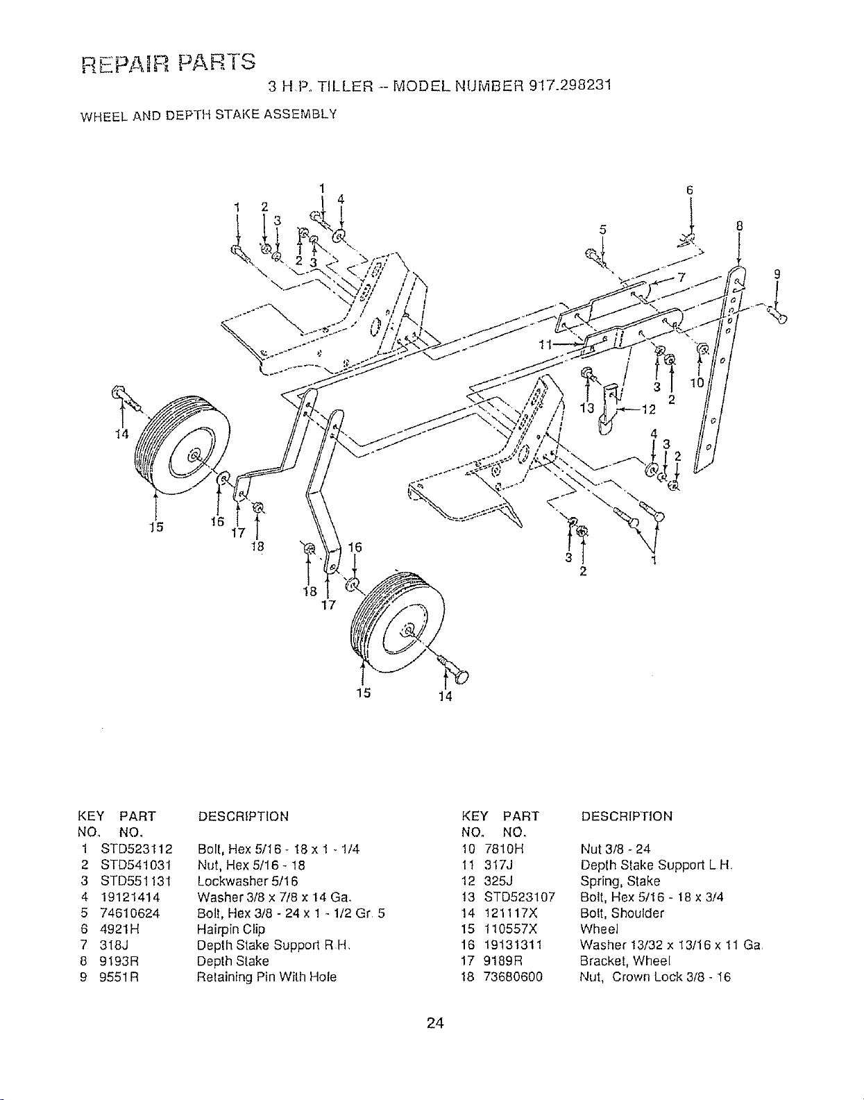
RLPA, ' PARTS
3 HF° TILLER .-- MODEL NUMBER 917.298231
WHEEL AND DEPTH STAKE ASSEMBLY
14
1 2
\
1
4
15
!6
18
"_ 16
18
17
2
15 14
KEY PART
NO. NO.
1 STD523112
2 STD541031
3 STD551131
4 19121414
5 74610624
6 4921H
7 318J
8 9193R
9 9551R
DESCRIPTION
Bolt, Hex 5/16- 18 x 1 - 1/4
Nut, Hex 5/16- 18
Lockwasher 5/16
Washer 3/8 x 7/8 x 14 Ga,
Boll, Hex 3/8- 24 x 1 - 1/2 Gr 5
Hairpin Clip
Depth Stake Support RH,
Depth Stake
Reiaining Pin With Hole
KEY PART
NO. NO.
10 7810H
11 317J
12 325J
13 STD523107
14 121117X
15 110557X
16 19131311
17 9189R
18 73680600
DESCRIPTION
Nut 3/8 - 24
Depth Stake Support L H
Spring, Stake
Bolt, Hex 5/16 - /8 x 3/4
Bolt, Shoulder
Wheel
Washer 13/32 x 13/16 x 11 Ga
Bracket, Wheel
Nut, Crown Lock 3/8 - 16
24
• '} ,, • "" k_ ,%-
3 H.P. TILLER --MODEL NUMBER 917298231
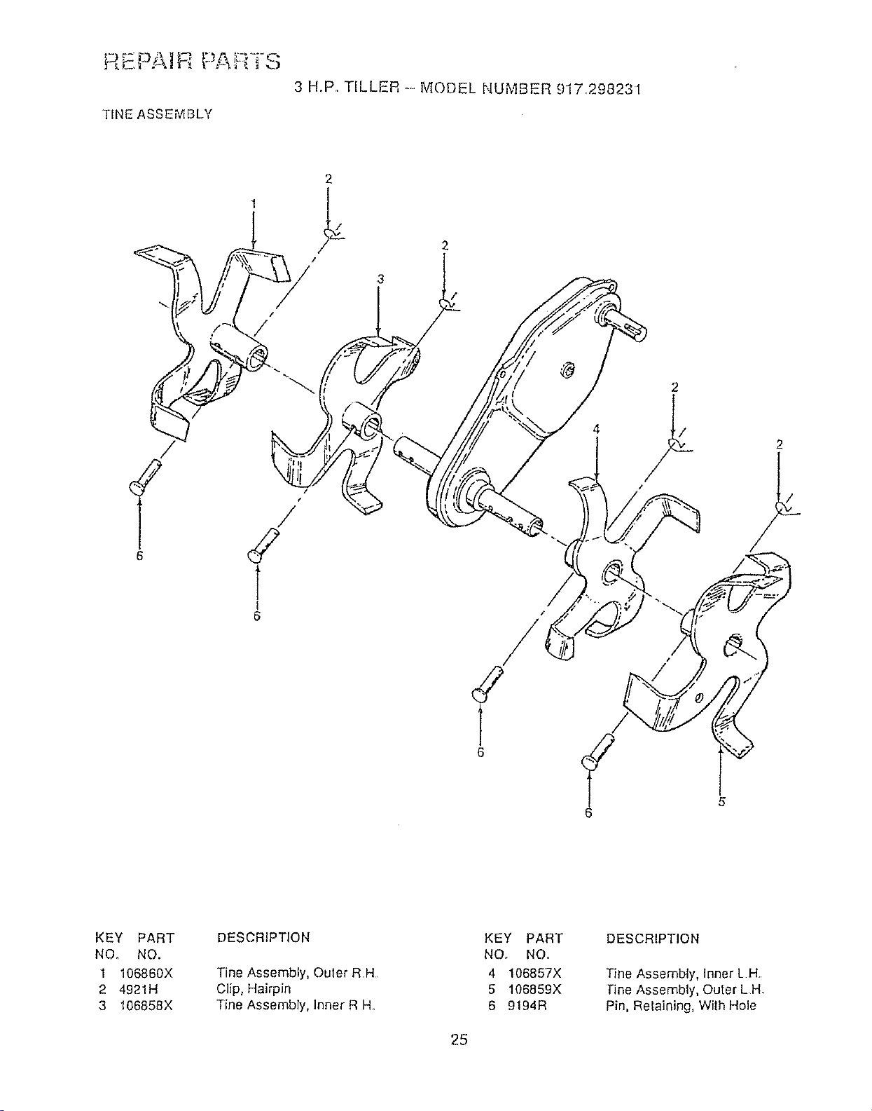
TINE ASSEMBLY
6
t
I
6
4
2
2
6
KEY PART
NO, NO.
1 106860X
2 4921H
3 106858X
DESCRIPTION
Tine Assembly, Outer RH
Clip, Hairpin
Tine Assembly, Inner R H.
KEY PART
NO. NO.
4 106857X
5 106859X
6 9194R
DESCRIPTION
Tine Assembly, Inner LH
l"ine Assembly, Outer LH.
Pin, Retaining, With Hole
25
m._r-E_ _ [!-.-_ _-,_ _ZY'I,-C_
3 HP.. TILLER -- MODEL NUMBER gl7,298231
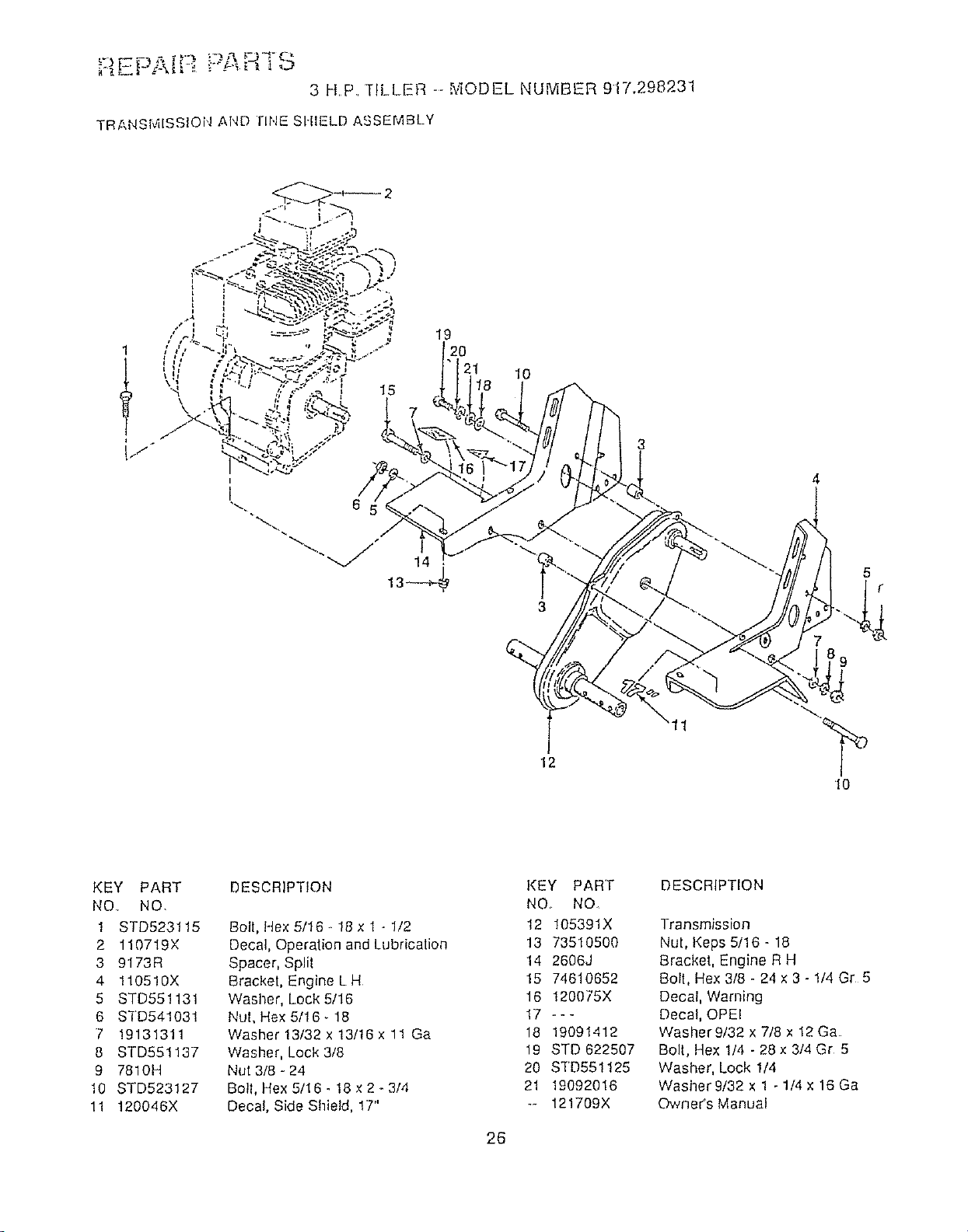
TRANSMISSION AND rlr,lE SHIELD ASSEMBLY
1
I f/,,,
i
19
I0
3
12
11
5
7
10
KEY PART
NO.. NO.
1 STD523115
2 110719X
3 9173R
4 1105!0X
5 STD551131
6 STD541031
7 19131311
8 STD551137
9 7810H
10 STD523127
11 120046X
DESCRIPTION
Boll, Rex 5/16 .. 18 x 1 - 1/2
Decal, Operation and Lubrication
Spacer, Splil
Bracket, Engine L H
Washer, Lock 5/16
Nut, Hex 5/16.18
Washer 13/32 x 13/16 x 11 Ga
Washer, Lock 3/8
Nut 3/8 - 24
Bolt, Hex 5/16. 18 x 2 _3/4
Decal, Side Shield, 17"
KEY PART
NO, NO
12 105391X
13 73510500
14 2606J
15 74610652
16 120075X
17 ---
18 19091412
19 STD 622507
20 STD551125
2f 19092016
- 121709X
DESCRIPTION
Transmission
Nul, Keps 5/16 - 18
Bracket, Engine R H
Boll, Hex 3/8 - 24 x 3 - 1/4 Gr 5
Decal, Warning
Decal, OPEl
Washer 9/32 x 7/8 x 12 Ga
Bolt, Hex 1/4 - 28x 3/4 Gr 5
Washer, Lock 1/4
Washer g/32 x 1 - 1/4 x 16 Ga
OwneCs Manual
26
REPAIR PAF,
3 H.P. T[LLER -- MODEL HUMBER 917,298231
ENGINE_BR_GGSANDSTRATTON-_MODELHUMBER 80202 TYPE HUMBER 236g-01
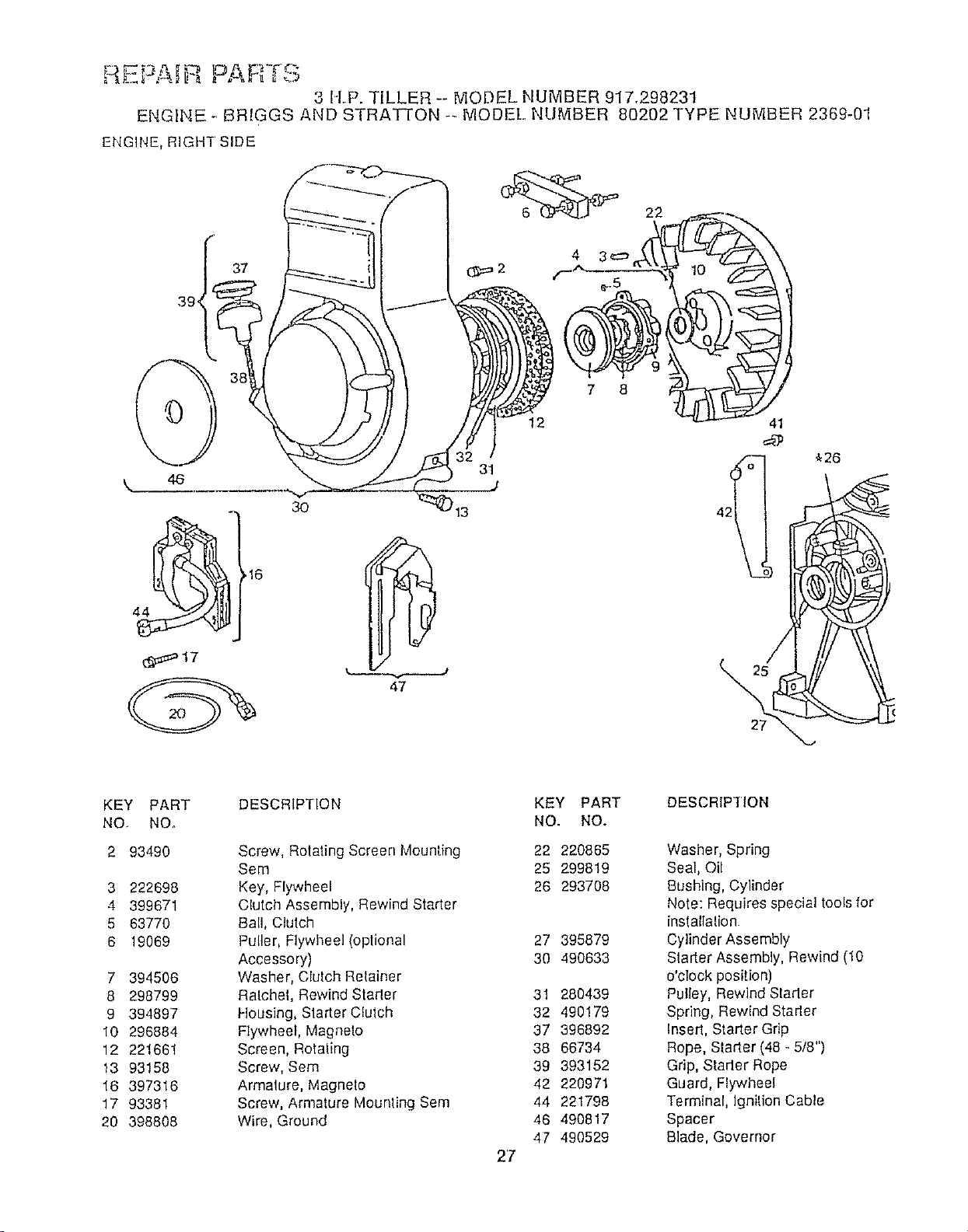
ENGINE, RIGI4T SIDE
0
37
3O
47
12
13
k
27
'_28
KEY PART
NO. NOo
2 93490
3 222698
4 399671
5 63770
6 19069
7 394506
8 298799
9 39489'7
10 296884
12 221661
13 93158
18 397318
17 93381
20 398808
DESCRIPTION
Screw, Rotaling Screen Mounting
Sere
Key, Flywheel
Clutch Assembly, Rewind Stader
Ball, Clutch
Puller, Flywheel (optional
Accessory)
Washer, Cluich Relainer
Ratchet, Rewind Slader
Housing, Stader Clutch
Flywheel, Magneto
Screen, Rotating
Screw, Sem
Armature, Magneto
Screw, Armature Mounling Sere
Wire, Ground
KEY PART DESCRIPTION
NO, NO.
22 220865
25 299819
26 293708
27 395879
30 490633
31 280439
32 490179
37 396892
38 66734
39 393152
42 220971
44 221798
46 490817
47 490529
2'7
Washer, Spring
Seal, Oil
Bushing, Cylinder
Note: Requires special tools for
installalion
Cylinder Assembly
Stader Assembly, Rewind (10
o'clock position)
Pulley, Rewind Starlet
Spring, Rewind Stader
Insed, Starter Grip
Rope, Starter (48 - 5/8")
Grip, Starter Rope
Guard, Flywheel
Terminal, Ignilion Cable
Spacer
Blade, Governor
3 H.P. TILLER-- MODEL NUMBER 917.298231
ENGINE- BRIGGS AND STRATTON -" tViODEL NUMBER 80202 TYPE NUMBER 2369-01
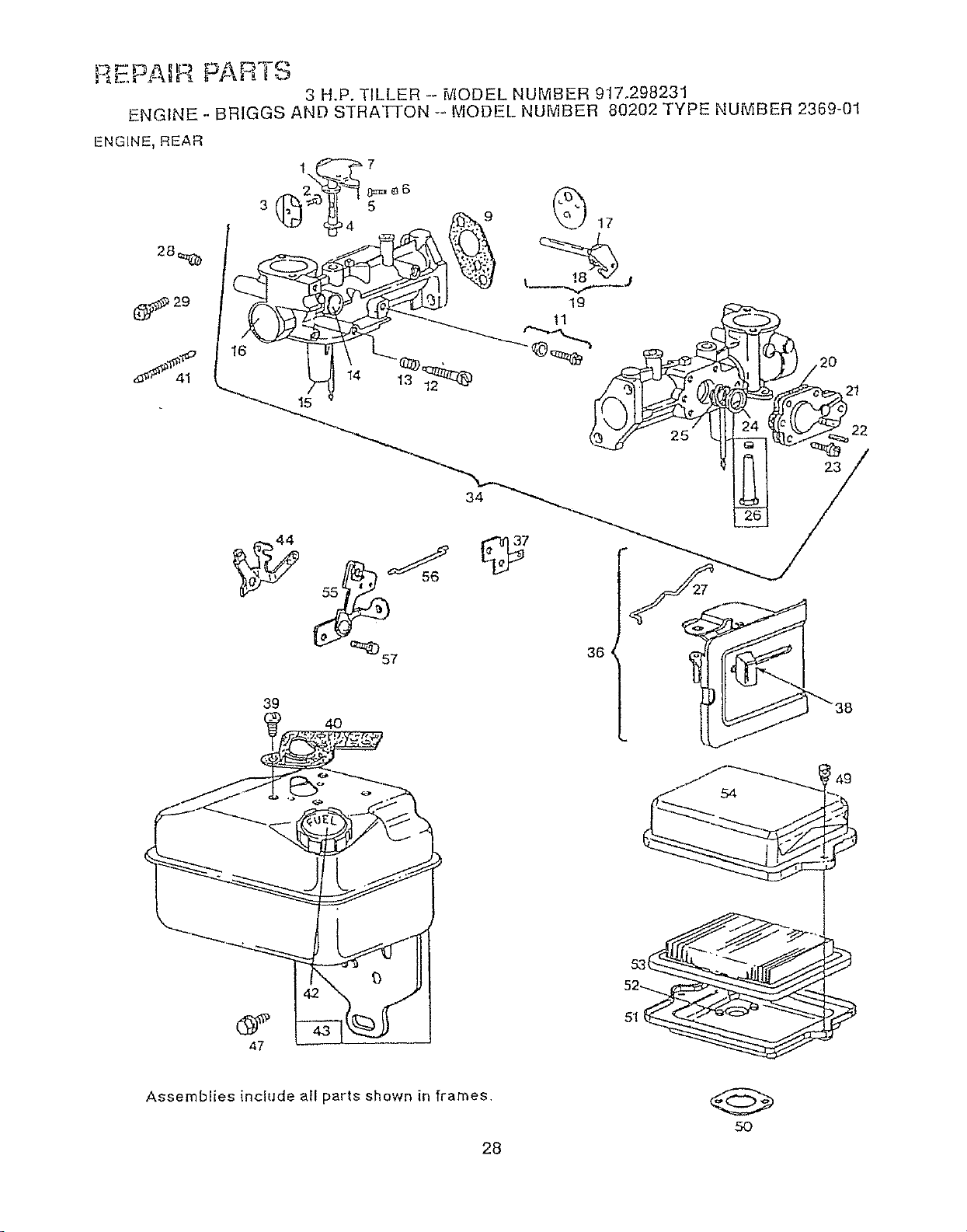
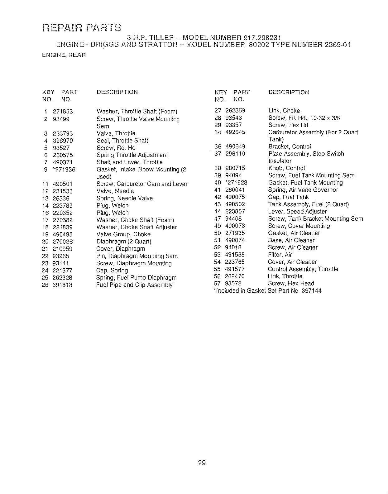
ENGINE, REAR
(_!_ 29
S 41
34
36
39
4O
47
5O
! 49
Assemblies include all parts shown in frames
28
3 H°P. TILLER -- MODEL NUMBER 917,298231
ENGINE - BRfGGS AND STRAI-rON -- MODEL NUMBER 80202 TYPE NUMBER 2369-01
ENGINE, REAR
KEY PART DESCRIPTION KEY PART DESCRIPTION
NO. NO. NO. NO.
1 271853
2 93499
3 223793
4 398970
5 93527
6 260575
7 490371
9 *271936
11 490501
12 231533
13 26336
14 223789
16 220352
17 270382
18 221839
19 490495
20 270026
21 210959
22 93265
23 93141
24 221377
25 262328
26 391813
Washer, Throttle Shaft (Foam) 27 262359
Screw, Throttle Valve Mounting 28 93543
Sem 29 93357
Valve, Throtlle 34 492645
Seal, Throttle Shalt
Screw, Rd Hd 36 490649
Spdng Throttle Adjustment 37 296110
Shaft and Lever, Throttle
Gasket, Intake Elbow Mounting (2 38 280715
used) 39 94094
Screw, Carburetor Cam and Lever 40 "271928
Valve, Needle 41 260041
Spring, Needle Valve 42 490075
Plug, Welch 43 490502
Plug, Welch 44 223857
Washer, Choke Shaft (Foam) 47 94408
Washer, Choke Shaft Adjuster 49 490073
Valve Group, Choke 50 271935
Diaphragm (2 Quart) 51 490074
Cover, Diaphragm 52 94018
Pin, Diaphragm Mounting Sere 53 491588
Screw, Diaphragm Mounting 54 223765
Cap, Spring 55 491577
Spring, Fuel Pump Diaphragm 56 262470
Fuel Pipe and Clip Assembly 57 93572
"Included in Gasket
Link, Choke
Screw, Fi[ Hd., 10-32 x 3/8
Screw, Hex Hd
Carburetor Assembly (For 2 Quart
Tank)
Bracket, Control
Plate Assembly, Stop Switch
Insulator
Knob, Control
Screw, Fuel Tank Mounting Sere
Gasket, Fuel Tank Mounting
Spring, Air Vane Governor
Cap, Fuel Tank
Tank Assembly, Fuel (2 Quart)
[ever, Speed Adjuster
Screw, Tank Bracket Mounting Sere
Screw, Cover Mounting
Gasket, Air Cleaner
Base, Air Cleaner
Screw, Air Cleaner
Filter, Air
Cover, Air Cleaner
Control Assembly, Throttle
Link, Throttle
Screw, Hex Head
Set Part No 397144
29
RE_-A[,'_ PAn _ o
3 H.P. TILLER - MODEL NUMBER 917.298231
ENGINE _ BRIGGS AND STRATTON -- MODEL NUMBER 80202 TYPE NUMBER 2369-01
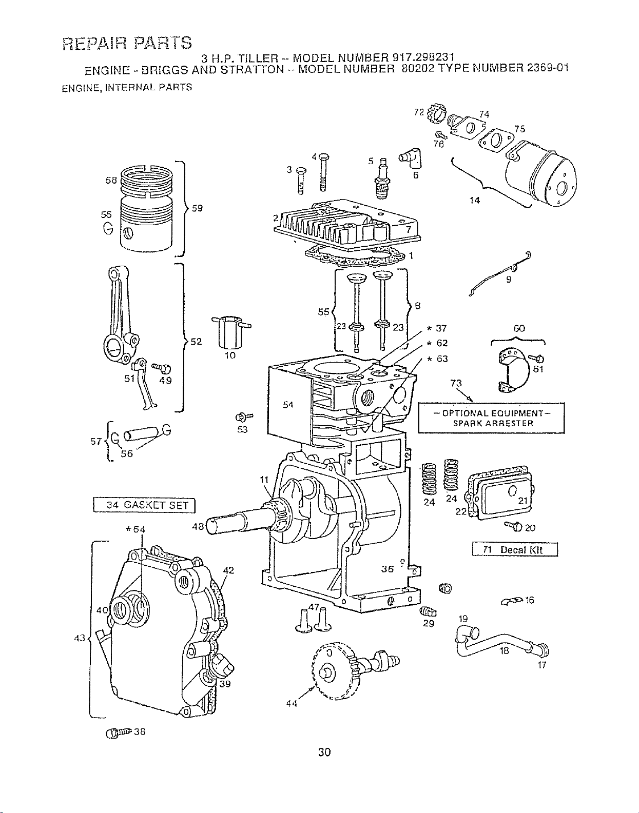
ENGINE, INTERNAL PARTS
5 49J
10
53
4_3_
34 GASKET SET ]
*64 48(
40!
(_38
42
39
72
37 60
* 62 r'_
7X
-- OPTIONAL EQUIPMENT-
SPARKARRESTER
11
! 71 Decal Kit 1
44
19
17
30
PARTS
3 H.P. TILLER - MODEL NUMBER 917'.29823-I
ENGINE - BRIGGS AND STRAI-rON-- MODEL NUMBER 80202 TYPE NUMBER 2369-01
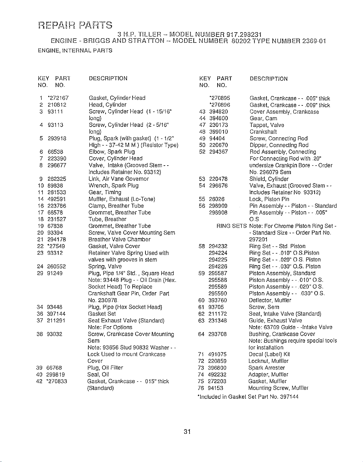
ENGINE, INTERNAL PARTS
KEY PAR_ DESCRIPTION KEY PART DESCRIPTION
NO, NO. NO, NO,
1 "272167 Gasket, Cylinder Head "270895
2 210812 Head, Cylinder '270896
3 93111 Screw, Cylinder Head (1 - 15/16" 43 394820
long) 44 394800
4 93113 Screw, Cylinder Head (2 - 5/16" 47 230173
long) 48 399010
5 293918 Plug, Spark (with gasket) (1 - 1/2" 49 94404
High - - 37-42 MM ) (Resistor Type) 50 220670
6 66536 Elbow, Spark Plug 52 294367
7 223390 Cover, Cylinder Head
8 298677 Valve, intake (Grooved Stem- -
includes Retainer No. 93312)
Link, Air Vane Governor
Wrench, Spark Plug
Gear, Timing
Muffler, Exhaust (Lo-Tone) 55 26026
Clamp, Breather Tube 56 298909
Grommet, Breather Tube 298908
Tobe, Breather
Grommet, Breather "l-ube RING
Screw, Valve Cover Mounting Sere
Breather Valve Chamber
Gasket, Valve Cover 58 294232
Retainer Valve Spring Used with 294224
valves wilh grooves in stem 294225
Spring, Valve 294226
Plug, Pipe 1/4" Std, Square Head 59 295587
Note: 93448 Plug - - Oil Drain (Hex. 295588
Socket Head) To Replace 295589
Crankshaft Gear Pin, Order Pad 295590
No. 230978 60 393760
Plug, Pipe (Hex Socket Head) 61 93705
Gasket Set 62 211172
Seat Exhaust Valve (Standard) 63 231348
Note: For Options
Screw, Crankcase Cover Mounting 64 293708
Sere
Note: 93656 Stud 96832 Washer - -
Lock Used to mount Crankcase 71 491075
Cover 72 220859
Plug, Oil Filter 73 396800
Seat, Oil 74 492232
Gasket, Crankcase - _ 015" thick 75 272203
(Standard) 76 94153
9 262325
10 89838
11 261533
14 492591
16 223786
17 66578
18 231527
19 67838
20 93394
21 294178
22 *27549
23 93312
24 260552
29 91249
34 93448
36 397144
37 211291
38 93032
39 66768
40 299819
42 '270833
53 220478
54 296676
Gasket, Crankcase - - 005" thick
Gasket, Crankcase - - .009" Ihick
Cover Assembly, Crankcase
Gear, Cam
Tappet, Valve
Crankshaft
Screw, Connecting Rod
Dipper, Connecting Rod
Rod Assembly, Connecting
For Connecting Rod with .20"
undersize Crankpin Bore _- Order
No. 296079 Sem
Shield, Cylinder
Valve, Exhaust (Grooved Stem * -.
includes Retainer No 93312)
Lock, Piston Pin
Pin Assembly - - Piston - - Standard
Pin Assembly - - Piston - - .005"
OS
SETS Note: For Chrome Pislon Ring Set -
- Standard Size - - Order Part No
297201
Ring Set - - Std Piston
Ring Set - - 0t0" O &Piston
Ring Set - - .020" OS Piston
Ring Set -.- .030" O.S. Piston
Piston Assembly, Standard
Piston Assembly - -010" OS.
Piston Assembly - _020" OS.
Piston Assembly - - 030" OS.
Deflector, Muffler
Screw, Sere
Seat, intake Valve (Standard)
Guide, Exhaust Valve
Note: 63709 Guide - -intake Valve
Bushing, Crankcase Cover
Note: Bushings require special tools
for inslallalion
Decal (Label) Kil
Locknut, Muffler
Spark Arrester
Adapter, Muffler
Gasket, Muffler
Mounling Screw, Muffler
'Included in Gasket Set Part No. 397144
31
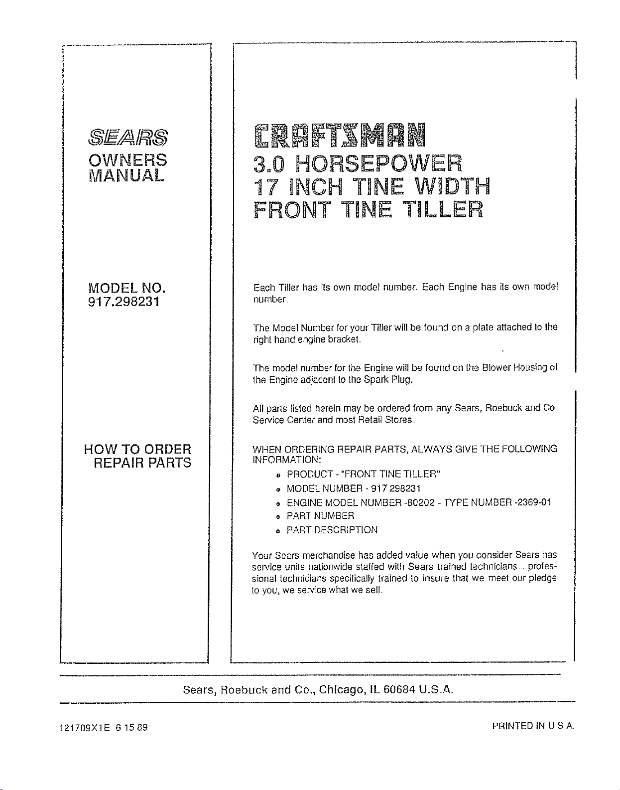
OWNERS
MANUAL
MODEL NO.
917.298231
HOW TO ORDER
REPAIR PARTS
3.0 HORSEPOWER
!7 INCH TINE WtDTH
FRONT TINE TILLER
Each Tiller has ils own model number. Each Engine has its own model
number
The Model Number for your T]ller will be found on a plate attached to the
right hand engine bracket.
The model number for the Engine will be found on the Blower Housing of
the Engine adjacent to the Spark Plug.
All parts listed herein may be ordered from any Sears, Roebuck and Co.
Service Center and most Retail Stores.
WHEN ORDERING REPAIR PARTS, ALWAYS GIVE THE FOLLOWING
INFORMATION:
o PRODUCT - "FRONT TINE TILLER"
a MODEL NUMBER- 917298231
• ENGINE MODEL NUMBER -80202 -TYPE NUMBER -2369-01
o PART NUMBER
o PART DESCRIPTION
Your Sears merchandise has added value when you consider Sears has
se[',,ice units nationwide staffed with Sears trained technicians profes-
sional technicians specifically trained to insure that we meet our pledge
to you, we service what we sell.
Sears, Roebuck and Co,, Chicago, IL 60684 UoSoAo
121709XIE 61589 PRINTED INUSA